Most home and hobby electronics projects consist of prototyping. "Proto" means "first," so a prototype is the first version, model, or instance of something being built. All big projects and products begin with a prototype, just to see how the idea works out. Since most of us are not in business to construct products, just about everything we build can be considered a prototype! If you go on to improve your circuit, as many of us do, each model is a prototype for the next.
Much of the work of prototyping involves packaging the electronics. You may build the electronics from individual components — some techniques for building this type of circuit are covered in Chapter 6.
As electronics manufacturing has become more and more efficient, it has also become more and more common (and cheaper!) to simply use ICs or modules that do the job. All you have to do is provide power, input and output connections, and the necessary controls. That's what the tasks in this chapter will illustrate.
It's quite unlikely that all of the parts you have or buy will exactly match those in this book. Don't be afraid to substitute and experiment! That's the fun of electronics as a hobby — trying something new and learning. If a figure shows a pushbutton switch and you have a toggle switch, that's fine! If you'd rather build your prototype in a coffee can than a plastic box, have at it. It's your prototype! The goal of this chapter is to give you some ideas about constructing electronic equipment and give you the confidence that you can create useful and interesting stuff at home.
While you're at it, don't forget to document what you build so that new technique or circuit is recorded for posterity! Keep a notebook handy for notes, schematics, layouts, plans, and ideas. You won't regret it when you need to duplicate or repair one of your creations.
This audio level controller is a good example of the type of simple gadget that a beginning circuitbuilder needs around the shop. It's quite common to want to use the audio output of a music player or stereo as input to some other circuit or recorder. However, the output voltage of these devices is often too high to apply directly to a recording input. Some kind of level reducer is needed.
Figure 5-1 shows the schematic of a simple level controller. The left and right audio signals are each connected to a variable resistor (also called a potentiometer or just pot for short). The wiper of the pot (denoted by the arrow on the schematic symbol) slides along the surface of a resistive element (the resistor symbol). The position of the wiper on the element determines the resistance from the wiper to each end of the element. With one end of the element grounded and the signal applied to the other end, the wiper forms a voltage divider. The voltage on the wiper gets smaller as the wiper moves toward the grounded end of the element.

Figure 5-1. The Audio level controller: a pair of variable resistors (potentiometers) divide voltage and reduce input signal level.
The total resistance of the pots in the controller is 1 kΩ. If the amount of resistance from the signal end of the element to the wiper is RA and the resistance between the wiper and ground RB, then RA + RB = 1 kΩ. The output signal level from the wiper will be as follows:
As the wiper moves along the element from the end at which the signal is applied toward ground, the output voltage gets smaller and smaller. The output signal can be varied from nearly the full input level to nearly nothing. This allows almost any audio source to be used for the input signal. If a splitter (an adapter used to allow two devices to connect to a single audio source) is used at the audio source's output, the recording device can even be operated while you listen to the music at full volume!
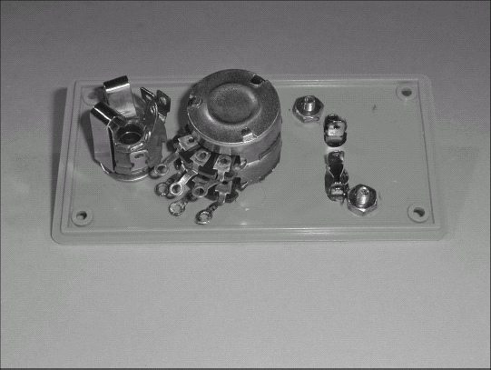
When you select an enclosure for your controller, make sure it's big enough to hold all the components — it's easy to underestimate how much depth or width is required. The enclosure should be large enough that you can access the terminals of the connectors and pots. If the enclosure is big enough that all of the components can be mounted on the lid (as shown in the photos), even better!
For more information on phone and phono-type headphone and stereo connectors, refer to the information about making cables in Chapter 10. You'll need a stereo patch cable to connect the level controller to the output of the audio source. In this chapter, the output of the controller is shown using separate phono jacks (typical of audio recording inputs). You may choose to substitute another phone jack if you intend to use the level controller with a computer sound-card input.
Making one of these regulators is a good example of using the power of an IC to perform almost all of the functions of a prototype. All the significant circuitry is contained within the single, three-lead body of a voltage regulator IC. Your job, as prototype designer, is to package it all so the circuitry stays cool and the input and output connections are secure.
The regulator changes the output of your car's electrical system (nominally 12V, but often anywhere between 10V and 15V) to a smooth, even 5V. The process of controlling an output voltage is called (logically enough) regulation and the devices that do the job are called regulators. The regulator will come in handy for running digital logic projects you might build for your car; it can also control devices that run from three 1.5V batteries, since 5V is reasonably close to the output voltage from three fresh batteries.
In this task, you'll adapt a commercial kit to a new purpose — making a simple alarm. There are so many good kits available that sometimes it's easier to use one for a new purpose than to design a completely new circuit from scratch. In this case, using an oscillator kit that costs less than $10, adding a speaker and enclosure from the junk box, a capacitor and a connector, and you've got a perfectly good alarm!
An alarm is a particularly useful thing to build. It doesn't have to be designed to catch a burglar; it can respond to any event that can close an electrical switch. You can use a thermostat, an airflow switch, a light-dark detector, a pressure switch, and even (yes) a security alarm switch. You can find a simple schematic for doing so at the end of the task, later in this chapter.
You'll have to choose from one of the many available oscillator or pulse-generator kits available. The Ramsey Electronics (www.ramseyelectronics.com) Kit UT-5, the "Universal Timer," is based on the popular 555 timer IC. (See Chapter 3 for more information about the 555 timer.) Depending on your intended use, the circuit can be wired as a delay, a single-pulse generator, or it can generate a continuous stream of pulses. Any oscillator kit that can drive a speaker to satisfactory volumes will work in this simple system.
The continuous mode is also known as astable (that is, "not stable," because the circuit jumps back and forth between two states, OFF and ON). When the kit is configured for the astable mode (certain components and jumper wires are installed), the output is a stream of pulses whenever power is applied. The frequency of the pulses is adjustable by a variable resistor. The speaker is connected directly to the output of the oscillator. The 10μF DC-blocking capacitor is required to prevent the speaker from carrying DC currents from the kit's output. Figure 5-2 shows how the addition of the external components creates the alarm.

Before you begin building anything, make a photocopy of the schematic and make sure you have all the parts ready to go. You'll need to mark off each connection as it's made. Don't forget to keep a notebook handy for notes, schematics, layouts, plans, and ideas.

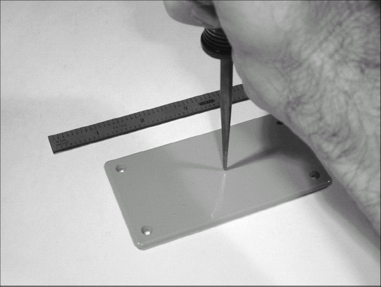
Lay out where each control and connector will go on the enclosure. Look carefully for mechanical interference or obstructions inside the enclosure that would prevent mounting a connector in the desired location. If some of the parts are mounted on the lid and some on the side, will they stay clear each other when the box is assembled? Mark the location of each connector and control.
Tip
If the hole is a mounting hole for a sheet metal or self-tapping screw, use a drill bit that is the same size as the inside of the threads. Hold the drill bit against the screw threads with the screw behind the bit. The threads should stick out past the sides of the bit, but the center portion of the screw should not be visible.
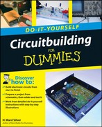
Centerpunch where each hole will be drilled.
Drill small pilot holes at each location with a ⅛″ drill bit. (Any size close to that will do.) If the holes are to be used for mounting screws, use a drill size guide to select the proper bit size.
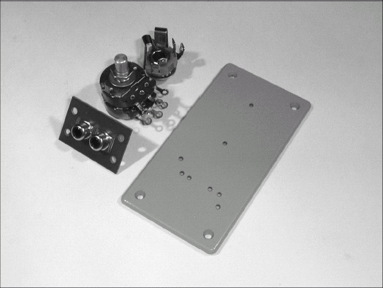
Use a hand reamer to increase the size of the holes if you're using a plastic enclosure. The hand reamer will gradually enlarge the hole without seizing in the hole or cracking the plastic. Reamers also work well in thin metal enclosures; drill bits tend to grab and tear sheet metal. If you decide to drill out the holes, use a vise to hold the material.
Mount all of the connectors and controls on the enclosure. Use lock washers under nuts inside the enclosure. Flat washers should be used on the enclosure's outside surface for any of the controls or connectors that mount in a single hole, such as the phone jack and volume control shown in the figures. Tin all contacts and terminals.
Tip
When using a reamer, turn it continuously in one direction. This helps ensure that the hole will be round and not oblong or star-shaped.
Tip
For connectors where the terminals are very close together, such as output phono plugs, it may be easier to drill small holes for each and then use a file or utility knife to make a slot-shaped hole.
Use a multimeter's resistance scale or continuity tester to determine which of the phone jack terminals are Tip, Ring, and Sleeve. The Tip contact will be the one that contacts the plug farthest from the mounting bushing. Insert a phone plug into the jack if there is any doubt about which contact is which.
Use the multimeter's resistance scale to identify the wiper terminals of the pots. (They're usually the ones in the center of the three terminals.) Now turn the shaft of the control all the way counterclockwise. This will be the lowest-level setting. Determine which of the remaining two terminals has the lowest resistance to the wiper terminal. That terminal will be the one connected to ground; the other will be connected to the input signal.

Connect the phone jack's sleeve terminal to the pot's ground terminals and the phono jack's shell terminals. You can make individual connections with separate pieces of wire or run a single bare wire to connect all five terminals (as shown in the figure).

Measure and cut pieces of wire to connect the signal terminals. The wires should be long enough that they're not under any tension when soldered to the terminals. Strip and tin each end of the wires. Solder one end of each wire to an input or output connection.
Tip
Get into the habit of using different colored wires for different audio channels. That makes tracing connections a lot easier and reduces the chances of error when wiring the circuit.
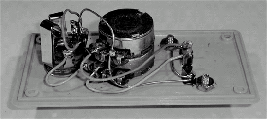
Connect the signal wires from the input connectors to the signal input terminals of the pot. Connect the signal wires from the output connectors to the wiper terminals of the pot.

Assemble the enclosure and install the knob on the pot. To align the knob, turn the shaft of the pot fully counterclockwise and orient the knob so that it will be in the "7 o'clock" position. Tighten the knob setscrew(s). Label the box any way you choose — you're done!

Apply an input signal from a stereo audio source and connect the outputs to a stereo receiver or other device with separate channel inputs. While listening to the output of the controller, adjust the levels and be sure turning the knob clockwise increases the output levels and vice versa.
Note
If the levels increase when the knob is turned counterclockwise, you have the ground and signal terminals of the pot reversed. Swap the ground and signal connections. If the channels themselves are reversed (left channel audio on the input appears as right channel audio on the output), exchange the signal wires at the input connector. (Don't change the ground connection.)

The regulator IC is a type of circuit known as a linear regulator. The term Less than half "linear" is used because the circuitry inside the regulator makes continuous adjustments to keep the output voltage at 5 V. Regulation of the output voltage is achieved by adjusting the drive current to an internal pass transistor through which all of the regulator output current flows. So the linear regulator is really just a kind of smart resistor. The circuitry acts like a resistor whose value constantly changes to just the right value, creating enough voltage drop from the input to the output to maintain a 5V output voltage. (For more information on voltage drops and Ohm's Law, see Chapter 12.)
Like a resistor, the regulator also generates heat. The amount of heat generated in watts (called power dissipation) is equal to the current through the regulator times the voltage from its input to output leads. For example, if 100 mA is flowing through the regulator with 12V at the input and 5V on the output, the power that must be dissipated is 0.1 × (12 - 5) = 0.7 watts. This amount of heat will cause the regulator IC to get warm to the touch, but not blistering hot. Raise the current close to 1 amp, however, and the entire circuit board will get warm as the heat is transferred through the regulator's metal tab to the PC board.
The 7805 regulator has another trick up its sleeve, however. If it senses its temperature rising too high, it shuts itself off until it cools back down! In that sense, it is almost immune to short-circuits! You can tell when the regulator is engaging in thermal shutdown because the output voltage will drop to a low value, hiccuping back to 5V for short intervals before being turned off again.

Start by making a photocopy of the schematic and making sure you have all the parts ready to go. You'll need to mark off each connection as it's made.

Cut a piece of PC board to fit the inside of your enclosure using a sharp utility knife and a straightedge. Place the straightedge on the PC board and score it with the knife until the copper cladding has been cut through.
Tip
If the PC board has copper cladding on both sides (double-sided board) turn it over and score it on that side, directly under the first cut. Then break the board over the edge of your workspace or in a vice.

Trim any burrs or slivers from the edge of the board. Then clean one surface with steel wool or a synthetic scrubbing pad. The copper should be clean and bright.
Drill a 5/32" or 3mm hole in the PC board to mount the 7805 regulator chip in the center of the board. (If you have any thermal compound, put a film of it on the underside of the 7805 where the metal surface will contact the copper surface of the PC board.) Use a ⅜″ to ½″ long 6-32 screw (6-32 is a standard screw size meaning the body size is #6 with 32 threads-per-inch), nut, and lock washer to attach the 7805 to the board.

Bend the ground pin of the 7805 so that it is flat against the PC board surface and solder it to the PC board. Bend the two remaining leads up at a 45-degree angle.
Cut the cigarette lighter cord in half. Use your multimeter's resistance scale or continuity function to determine which of the wires goes to the ground contact of the lighter and to whichever contact of the output connector (if any) you wish to be grounded. Strip and tin 1/4″ of each wire. If you are going to bring the cords through the walls of the enclosure, drill the necessary holes and insert the wires now.

Drill holes at two edges of board big enough that the cord's cut ends will pass through. Insert the cords, input on the left, through the holes and tie a Western Union knot in the wires (see Chapter 9) to keep them from unraveling.

Solder the ground wires of the cords to the PC board.

Tin the remaining leads of the 7805 and solder the capacitors from the input and output leads to ground. C1 connects from the input lead to the PC board and C2 connects from the output lead to the PC board. Be sure to connect C2 with the proper polarity.
Trim the leads of D1 to about 1/2″ long and tin them. Solder the cathode lead (the package has a stripe next to the cathode lead) to the input pin of the 7805 with the diode parallel to the PC board surface.

Solder the positive input wire to the anode lead of D1. Solder the positive output wire to the output lead of the 7805.
Test the regulator by inserting the cigarette lighter plug into the car's socket. (You may have to turn on the vehicle's ignition for voltage to be present at the cigarette lighter.) You should measure a steady 5V at the regulator's output between the positive output lead and ground (the surface of the PC board.)
Warning
Don't connect this regulator directly to your car battery without adding in-line fuses as shown in Chapter 7! A short circuit in the regulator will cause the input cord to overheat and possibly start a fire.
Note
If there is no output voltage at the output pin of the regulator (measure with the voltmeter's negative lead connected to the PC board surface), confirm that there is input voltage from the cigarette lighter plug and that D1 is installed with the proper orientation. If the output voltage is 0 or significantly lower than 5 V and the regulator gets hot, you may have a short circuit in the output or C2 has been installed with the wrong polarity.
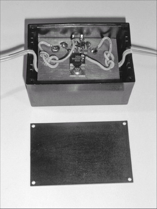
Put the assembled regulator into the enclosure. In the photo, a utility knife was used to make notches in the enclosure's edges slightly smaller than the input and output cords. When the enclosure's top was attached it will capture the cord between the top and sides, providing some strain relief for the cords. If the hole winds up big enough for the wires to move freely, add some hot glue on the inside of the enclosure to keep them from moving.
Label the regulator and document your work in your notebook.
A portable or temporary alarm combined with some kind of sensor can be a handy gadget. The alarm shown in this task can be used with a thermostat, a tip-over detector, a magnetic intrusion sensor — any type of sensor that acts like a switch and makes a connection between two terminals when it is tripped or activated. This task combines a speaker and an audio oscillator into a simple alarm system with the sensor of your choice.

Start by assembling the oscillator kit as directed by the manufacturer's instructions. (Chapter 4 contains additional information on building circuits on PC boards.)
Tip
When assembling kits, add your own sockets if they're not provided. This makes replacing a chip easy.

Collect the parts for the project and determine how your oscillator kit can be mounted in the enclosure. The kit used here does not have mounting holes, so a stick-on wire clip was used. These can be found in the electrical section of hardware stores.

Mark, centerpunch, and drill pilot holes for the speaker mounting screws and the phone jack. Use a hand reamer (see the task "Constructing the Level Controller" earlier in this chapter for information on using a reamer) to enlarge the hole for the phone jack. Mount the speaker and phone jack in the enclosure.
Tip
Hardware and appliance stores are great sources of inexpensive and novel mechanical components for experimenters. Show your project to a clerk and explain the problem you're trying to solve; he or she may have just the right part!
Tip
Be sure to use lock washers when installing any kind of vibrating component. Long periods of use can cause nuts to unscrew themselves from the vibration.

Cut some pieces of hookup wire and solder them to the assembled kit for power, ground, and audio output connections. The required length of the wires depends on the size of your enclosure and on how the various pieces are mounted in it.

Mount the assembled kit in the enclosure, using whichever method you've selected. The figure shows the kit held securely in an adhesive-backed plastic clip attached to the lid of the enclosure.
Solder the wire that supplies the kit with positive voltage to the phone jack's tip terminal. Solder the ground wire to the phone jack's sleeve terminal. (See Chapter 10 for more information on phone plugs.) Solder the kit's output wire to one of the speaker terminals — either will do.

Solder the 10μF capacitor's positive lead to the remaining speaker terminal and the capacitor's other lead to the phone jack's sleeve terminal (ground).

Connect +5 to +15 volts to the assembled alarm by connecting a two-conductor cable to the phone plug. Whenever voltage is applied to the alarm (such as through an alarm switch, as shown in the figure), the speaker will sound. The kit used in the figure has an adjustable tone, as well.
