
So far, this book has been about learning the skills of building circuits. There's more to building than just the mechanical construction, of course. Unless you're very lucky (or very, very good), there will be times when that circuit or project or system that you just assembled doesn't work. What then? This chapter shows you how to cope.
Tip
It's a little-known secret (kept in confidence by the experts) that all electronics works because of the Magic Smoke inside every component. If you let the Magic Smoke out, it stops working, it's that simple! (Well, at least nobody's been able to prove otherwise.)
In these few pages, it won't be possible to give you step-by-step procedures for every contingency. In fact, that's not possible even in hundreds of pages! Every circuit and piece of equipment is a little bit different in the problems that beset it and how it acts in response. The goal of this chapter is to extend your circuitbuilding skills by introducing some basic methods that you can apply to all those different problems. After you get good at using them, you'll be pleased to learn how quickly the problems yield to your awesome tool kit!
Let's start at the beginning, shall we? Troubleshooting is what you do when something has failed. This implies that at some point the device has done what it's supposed to. Debugging is what you do when the device hasn't yet demonstrated that it's capable of doing what it's supposed to do. In both cases, the device is in a state of failure. (For the rest of this chapter, I'll use the term "troubleshooting" to include "debugging.")
What is failure? (Technically speaking, of course.) According to the American Society of Civil Engineers, "Failure is an unacceptable difference between expected and observed performance." Failure can be as simple as a power supply that won't turn on or as complex as a microprocessor circuit with occasional glitches. There are three parts to this definition of failure:
Expected performance: This is what the device is supposed to do. You have to be able to state clearly what the expected performance is. Otherwise you can't say whether it's broken or working!
Observed performance: This is what the device is actually doing. You also have to be able to say what it's doing; otherwise you can't really say how it failed!
Unacceptable difference: No device is perfect, so it will perform slightly differently than however it's specified to perform. Only when the discrepancy is large enough does it become failure.
Before you embark on those voyages of discovery we call troubleshooting, take some time to think about those three ideas. If they're complicated enough (or the device is complex enough), write down your thoughts. You need to begin with a good idea of why you're troubleshooting and what you intend to accomplish — even for simple repairs and tests.
After your acumen in electronics becomes known, you'll no doubt be visited on occasion by family and friends bearing gadgets and items in need of attention. When you ask what's wrong, the reply will be, "It's broken!" At this point, dialogue must take place as you extract the details of what "broken" means. A crack or fracture? Does it not turn on? Did the Magic Smoke get out? Use your best manner of interrogation to extract the details — because you'll need them!
Troubleshooting can feel a lot like running in circles — because it is! You start by noticing some kind of failure and then you start looking for the cause. Around and around you go! Eventually, the trouble is found (or you give up) and the thing gets fixed (or it doesn't). Isn't there a better way? Sort of. Figure 13-1 shows the game board on which troubleshooting is played.
Assess: Take the time to carefully observe the symptoms. This could mean turning it on and taking notes or it could mean taking detailed measurements.
Compare: Compare your observations to what the device is supposed to be doing. This could be described in a specification or maybe a user's manual. Be specific and try not to assume or guess.
Hypothesize: This really means that you think of reasons why the device could behave the way it does. Pick one reason and come up with measurements you could make to prove or disprove the reason. For example, "The output amplifier IC could be distorting because the power supply voltage is too low."
Measure: Go take those measurements so you can tell if your hypothesis is correct.
Make a change: If measurements show your hypothesis is correct, make a change to clear up the problem, such as an adjustment or replacing a component. If the hypothesis was not correct, compare again and come up with another hypothesis.
Compare again: After the change has been made, assess the symptoms again to see if they have gone away. If so, it's fixed — congratulations! If not, go around again!
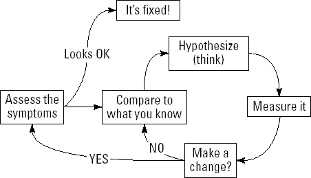
Figure 13-1. The troubleshooting process is a cycle of observation, thinking, measuring, and observing once again.
Keep this process in mind as you troubleshoot. Particularly with difficult problems, having the rules of the game in mind can help a lot!
You wouldn't play a complicated game with all the game pieces and cards in a giant heap (would you?) — and it's the same with troubleshooting. As you go around and around, it's easy to lose your place. Unless you organize your thoughts, that is.
Staying organized requires nothing more special than a pen and paper, as you can see in Figure 13-2. As you work through the problem, record your observations, your hypotheses, your measurements, thoughts that pop into your head, and anything else you notice or learn. That's what the log is — a record of the events that occur during the troubleshooting process.
Figure 13-2 shows an example of a troubleshooting log on the buffer amplifier circuit in Chapter 6. Let's say you built the buffer amplifier and it was working fine. Then one evening a thunderstorm blew through — and the next morning your buffer wasn't working any more. Uh-oh, it's time for a troubleshooting session!
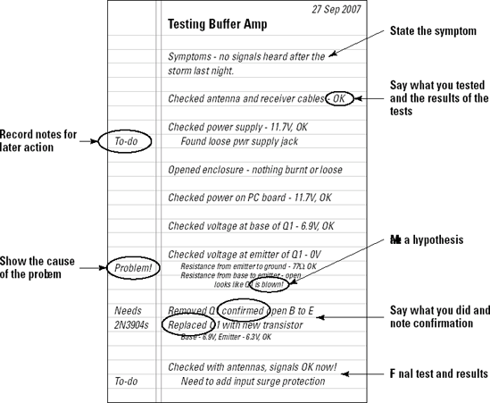
Figure 13-2. Keeping a troubleshooting log on notebook paper is an easy and inexpensive way to track problems and successes during troubleshooting.
Start with a clear label and date so if you have to set aside the project for a while, you'll know which notes apply to which parts and when they were taken. Then describe the symptoms. In this case, the amplifier didn't work after the storm.
As you take each step, write down what you're doing, the results of any measurements, and whether the measurements were normal or not. As you proceed, you'll probably notice other things that might need doing later (such as fix that worn power supply cable and buy some more 2N3904 transistors). Note those things in the margins.
At some point, you'll probably find a probable or reasonable cause for the problem. In this case, no voltage at the transistor's emitter, indicating that the transistor itself may be bad. Note what makes you think it's a problem ("Resistance from base to emitter — open!"). If you make a hypothesis ("Looks like Q1 is blown"), write that down.
Whatever you decide to change — an adjustment, a component, a connector — note what you did, and whether any additional measurements were made. In this case, the suspected transistor was tested — and found to indeed have an open-circuited base-to-emitter junction. It was then replaced.
Note the results of the change. If this fixes the problem — or causes other measurements (such as circuit voltages) to return to normal — note what seems to have fixed the problem. You might want to make more detailed measurements later.
Note
A troubleshooting log is even more important during the debugging process when you're trying to get something to work the first time! You'll be making lots of measurements and changes. Without a log, it's easy to get lost and waste a lot of time!
After you've completed the troubleshooting, get out your notebook (it should never be far away from your workspace!) and write down what you've discovered. Take a photo or make a sketch if the information needs a visual description to be clear. Remember that you might not need that information for a long time — well after the details fade from memory.
Then go meet with your friends and share your latest story with them. Everyone loves a good troubleshooting tale. They'll pepper you with questions, tell a tale or two of their own, and the whole group will learn something. If the information is really valuable, consider giving a short talk or demonstration to your club or team. That's how we all learn!
Although I don't recommend that you intentionally break equipment or damage your circuits, I do urge you to take the opportunity to attempt repairs when you can. The very best way to learn about any piece of equipment is to repair it! By working on equipment you didn't build or design, you'll learn to unravel many small problems in the course of the troubleshooting session.
Note
If all your equipment is working just fine, why not go scrounge something from a friend or relative? Garage sales and thrift stores are also full of stuff that doesn't work perfectly and can be fixed. Sometimes a repaired item can be resold at your own garage sale!
Certainly, instruments such as multimeters and counters are required to make electrical measurements, but you also possess your regular senses to help you zero in on trouble spots.
Your eyes: Learn to scan the outside and inside of equipment and listen to that little voice in your head saying, "That looks funny!" Hold things up to the light or look at them from different or unusual angles. Learn to spot discolorations from heat or corrosion. Learn what components and parts are supposed to look like.
Your nose: One of the least mentioned, but most frequently used workshop senses is that of smell. Take note when something smells hot or there's an acrid smell around a piece of equipment. You'll soon learn to discriminate between the aroma of roasted resistor, toasted transistor, and cooked capacitor.
Your ears: Learn to listen for unwanted noise, audio levels that are too high or low, subtle characteristics of the different types of distortion, and hums or buzzes where they shouldn't be. These are clues that augment the electrical measurements.
Your touch: Even if you don't touch live circuitry (and you shouldn't!), touch will tell you when equipment or parts are too hot or not warm enough. Vibrations or wobbles are telling tips of imbalance or wear.
To paraphrase a popular saying, "If the power supply ain't happy, ain't nobody happy!" For electronic devices to work properly and reliably, the power source has to be happy. Ask experienced troubleshooters where they begin looking for the problem and chances are they'll tell you they check the power first.
Note
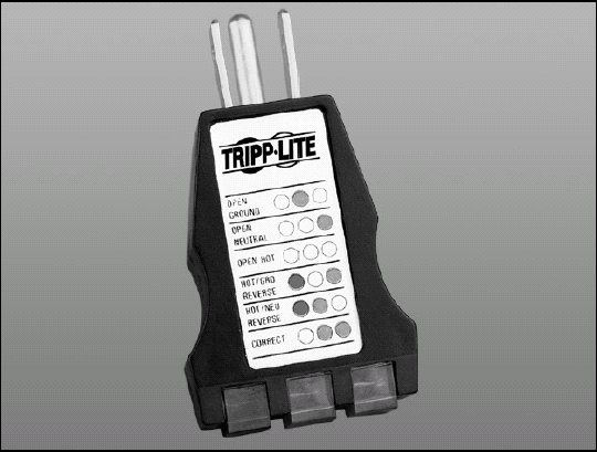
Power problems can begin at the wall socket. Repairmen who make house calls will tell you that many times the problem of an appliance that "doesn't work" is just that the line cord or "wall wart" transformer (the small power modules that plug into the wall socket) was unplugged or just loose. AC outlets can be loose or defective; circuit breakers may have been tripped, as well. So if your device runs from AC line current, make sure it's plugged in securely — and that the socket is live — by using a tester (as in Figure 13-3). You might save yourself a lot of time!
Power troubles can masquerade as other problems — hum, distortion, erratic operation, overheating, to name just a few. Whether the voltage is too high or too low, it's likely to have an effect on the circuits downstream. If you're chasing a gremlin that seems to be everywhere and nowhere at the same time, take a close look at the circuit power.
Fuses and circuit breakers are supposed to interrupt power when there's an overload. It isn't always obvious, however, that they've tripped. If the overload is severe (say, from a short circuit), the fuse is blown — pretty obvious. If the overload is light and prolonged, however, the fuse may simply sag until the element breaks — and that might not be obvious at first look. Fuse elements have also been known to break from vibration or high temperatures; this often occurs inside the metal end cap of glass cartridge fuses where it's hard to see. Don't assume the fuse is good — measure its resistance.
Circuit breakers mounted on equipment usually have a small button that pops out of the housing when the breaker trips. To reset the breaker, you push the button back in. The button may be loose after tripping and not fully extended, so it's not always clear that the breaker is really tripped. Double-check by testing voltage into and out of the breaker.
Note
A GFCI (ground-fault circuit interrupter) breaker trips if current between the hot and neutral wires is temporarily unbalanced. This is an indication of a shock hazard. GFCI breakers are installed in special sockets from which other sockets are wired. Even though the main breaker for the circuit may not be tripped, if the GFCI breaker has tripped the downstream sockets will not have power. GFCI outlets will often trip at current levels far below that of the main breaker and have been known to trip because they detect the signals of nearby transmitters.
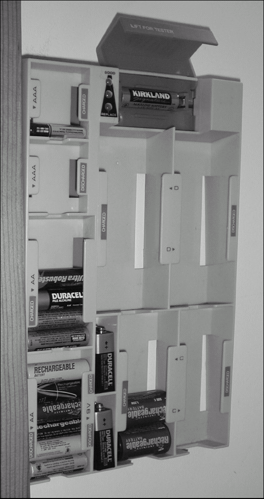
Batteries provide a steady source of DC, but not without their own set of special problems. (Battery types and capacities are discussed in Chapter 15.) The most common problem is a weak battery whose output voltage is fine — until current is drawn from it, at which time the voltage drops dramatically. You can see this effect in a flashlight using an incandescent bulb. With weak batteries, the bulb may burn brightly for an instant when turned on, then quickly fade to a dim light or go out entirely. When checking batteries, don't take their open-circuit voltage at face value. Test the voltage while drawing a few mA out of the battery with a 1 kω resistor, or use a battery tester, shown in Figure 13-4, that applies a load to the battery.
Note
Battery holders have been known to make poor contact, leaving the device user scratching his head after inserting fresh batteries, to no avail. If a battery has corroded in the holder, the resulting damage to the holder contacts can create a non- or poorly-conducting layer that prevents the battery terminal from making contact. Holders that aren't too badly corroded can be repaired by using a brass or steel brush to clean the contact.
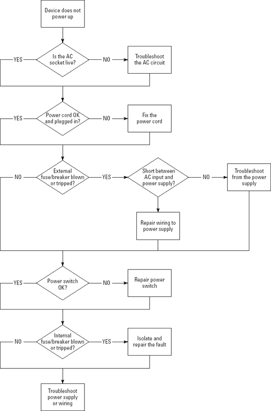
This part of the chapter is a general guide to help you organize your thoughts and attack power problems in a logical way. This process is presented in the form of a flow chart in which symbols represent actions, conditions, and decisions. Square boxes represent actions ("Test AC socket"). Diamonds represent decisions ("Is AC on?") and the conditions for the decision ("Yes" or "No") are shown on the arrowed lines indicating the path through the chart. (For more information on flow charts, read the Wikipedia entry at http://en.wikipedia.org/wiki/Flow_chart.)
Figure 13-5 shows a simple process of dealing with that most common of objects — an AC-powered device that won't turn on. This is good practice for more complicated troubleshooting and helps put you in that logical, "Just the facts, ma'am" frame of mind so critical to finding and repairing problems. The chart assumes that the device has an internal power supply that converts the AC to DC for the electronics — and that there is a power switch to turn the device on and off. If the device doesn't have fuses or circuit breakers, assume a YES for those steps and proceed.
The goal of the flow chart is to find any problems that may be present between the AC wall socket and the device's internal power supply. Every possible wiring configuration isn't covered, of course, but if you follow the general procedure, you're likely to find any problems that exist upstream of the internal power supply.
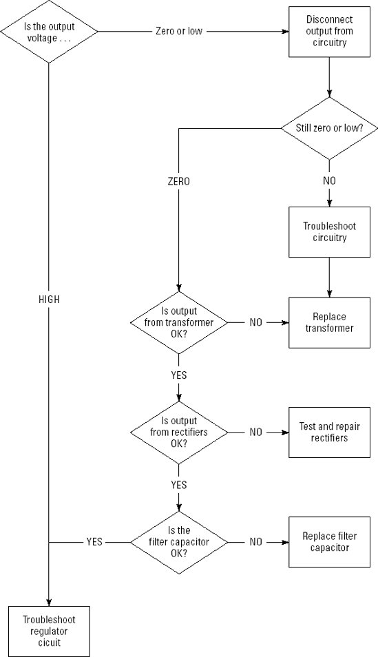
If you troubleshoot your way to the device's internal power supply, a new flow chart is in order. The most common linear power supply is usually a simple circuit consisting of a step-down transformer, a rectifier, a filter to smooth the rectified AC (pulses of DC current) into steady DC, and some voltage regulating circuitry. (An introductory description of power-supply circuits is online at www.williamson-labs.com.) Although a detailed troubleshooting plan for any linear supply is beyond the scope of this book, the flow chart in Figure 13-6 will provide some insight into whether your power supply is working the way it should. The flow chart assumes that AC input to the supply circuitry is all right (as determined by the flow chart in Figure 13-5) The downstream supplied circuitry may also overload the power supply or have its own problems, so be prepared to test it, too!
To help you look for problems, here's a list of common power supply failures and symptoms. Remember to follow the flow chart and don't jump to conclusions!
AC line fuse keeps blowing: Assuming there's no short-circuit before the power supply, you may have a short-circuit from one of these causes:
A defective rectifier or filter capacitor acting like a short-circuit
A short-circuit in the circuitry supplied
The power supply has overvoltage protection, and that circuit may be drawing too much current to protect the supplied circuitry
Regulator circuit is hot and shuts down: Usually a fault in the supplied circuitry that makes it draw too much current; output voltage will be low or zero.
Regulator transistors are blown: If these are shorted, the output voltage will be too high; if they're open, the output voltage will be zero or very low; if they're damaged but not completely gone, the output voltage may be okay as long as nothing is connected to the power supply — but it'll be low when a load is applied.
Excessive ripple (hum or buzz in output audio or other signals): Measure ripple on the power supply's output with a multimeter set to measure AC voltage; the usual cause is a defective filter capacitor at the rectifier output
Arcing (in high-voltage supplies, such as for televisions): The usual cause is dust buildup — remove dust and lint with a vacuum cleaner's crevice attachment and an old (clean!) paintbrush.
There are literally millions of different audio gadgets, yet most of the problems associated with them fall into a few categories with common causes. Figure 13-7 shows a flow chart that will help you through the following steps:
Disconnect the equipment's input cables one at a time until the problem goes away. Replace the cable to check if it's just a bad cable. If the problem comes back, it's in the equipment attached to the other end of that cable.
If the problem still exists after disconnecting all the cables, its cause is inside the equipment.
Make sure the equipment's power source or internal power supply is working properly.
In the case of hum or ground loop problems (covered in just a moment), try moving the equipment or changing the way the equipment is grounded. Reverse the AC line cord (if it's a two-prong cord) to see whether the problem changes.
These descriptions of problems and probable causes should help you analyze the symptoms and make your first hypothesis as discussed earlier.
Distorted audio (at normal listening levels) reflects an inability of the circuit producing the signal to accurately follow the input signal. Assuming the circuitry itself isn't damaged or designed to introduce distortion in the first place, look for the following external causes:
Input signal too high: Check the level of the audio signal at the input to the circuit or device. Distortion is a common result of connecting the input of high-gain circuits, such as microphone inputs, to line-level or speaker-level outputs.
Load is too heavy: Trying to drive a heavy load, such as speakers, with a low-power device designed for headphones can overload the output circuit.
Power supply problems: A power supply voltage that's too high or too low can upset the operation of amplifier circuits and cause distortion.
Hum is the contamination of signals with unwanted signals at the frequency of the power line, 60 Hz in North America. Hum is audible as a very low-pitched tone. It may be very loud or very soft, and is usually caused by electrical interference to the external connections to a piece of audio equipment, including microphones.
Note
Hum can be caused by sensitive circuits being placed too close to a power transformer. The magnetic fields around the transformer can cause small signals to be coupled into the electronics, causing hum.
Ripple may seem like hum, but it sounds a little different. Ripple is present at twice the power line frequency, or 120 Hz for a 60Hz line frequency. It's the result of the rectification process that turns AC into DC in the power supply. (See the preceding section on power supply troubleshooting.)
Note
Another source of hum is ground loops in which the ground connections between different pieces of equipment act as a pickup for magnetic fields, creating low-level hum in the audio circuits. To learn more about ground loops and how to eliminate them, read the tutorial at
www.angelfire.com/electronic/funwithtubes/Eliminating_Ground_Loops.html. |
After you've decided whether the problem is hum or ripple, follow the flow chart of Figure 13-7 to further isolate the problem.

Two kinds of audio noise are the most common; hiss or white noise and a crackling kind of noise. Both are obnoxious if unwanted.
Note
White noise gets its name because it's colorless, meaning equally strong at all frequencies. Another type of noise is pink noise, that decreases in amplitude with increasing frequency. Both are used for different purposes in audio systems and circuits.
Hiss at normal volumes generally indicates a defective audio circuit or device. You can quickly isolate the source of the hiss by disconnecting input connections until it goes away. If it doesn't go away, then it's being generated by the device you're listening to. Check all the controls to be sure you haven't accidentally caused high frequencies to be emphasized (such as turning off Dolby noise reduction on a Dolby-encoded tape playback deck) or left on some other amplifier circuit that has no input connection.
Crackling noise is usually caused by an intermittent or degraded contact somewhere in the system. Start by wiggling all input connections while listening to the noise. If one cable seems to cause the noise to start and stop, get louder, or disappear entirely, replace the cable and see whether the noise comes back. If wiggling cables doesn't affect the noise, disconnect the input connections until the noise goes away, then troubleshoot the noise source if you've found it.
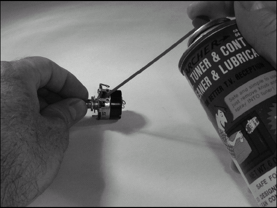
After the source of the noise is identified as a specific piece of equipment, check all its knobs and switches to see if one affects the noise more strongly than the other. Rotary volume and level controls often become intermittent after frequent use or being left in one position for a very long time. Noise levels can often be reduced by rotating the control or switch back and forth to take advantage of the natural wiping action of the contacts. If the noise is not completely eliminated, spray the component's contacts (as shown in Figure 13-8) with a contact cleaner spray such as is available from RadioShack (www.radioshack.com). Do not use non-cleaning sprays such as WD-40 or household cleaners.
Another type of crackling noise is caused by intermittent contacts at damaged or worn connectors. The contacts for jacks and plugs that are used frequently, such as for headphones or microphones can become worn or loose. The symptoms are usually crackling noises, hum, and buzz that are affected by wiggling the cable. Although the contacts in the connector can sometimes be bent or compressed to give a better connection, the noise almost always returns (usually at a completely inopportune moment). It's best to just replace the connector entirely, even if that is a pain.
Tip
Bad PC-board connections — particularly on headphone connections — can be caused by the mechanical stress of headphone connections cracking the solder joints of the headphone connector to the PC board. Unless the device is dropped with the headphones attached, the crack may be a hairline connection and difficult to see. Resolder all the connector contacts to the circuit board and use a magnifying glass to inspect the traces around the connector. Should any be found to be cracking (or already cracked), scrape away the solder mask over the trace and solder a short piece of fine wire across the crack to make the connection solid.
Tip
The techniques you learn to troubleshoot audio systems can also be applied to video equipment. Isolate the bad signal to just one input, check the cables, watch for sudden changes when moving equipment around, and be sure that the power supplies are clean.
Unlike digital circuits that use specific voltages to represent ON and OFF signals, analog circuits (sometimes called linear circuits) operate in a continuous range of voltage and current. The most common active components in analog circuits are bipolar transistors, FETs, and op-amps.
This section assumes that you've already checked the power and signal paths and have isolated a problem to a specific analog circuit. In addition, you've used your senses and haven't found any burnt or overheated components. You'll have to discover the problem electrically. Here it's assumed that you have only a multimeter and that limits the tests you can do, but a surprising amount can be learned with some simple DC voltage measurements.
Tip
For guidance on making measurements, refer to Chapter 12.
After confirming that the power to the circuit is all okay, take a look at the schematic for the circuit. If you're lucky, it will have typical voltage readings on it inside small circles or squares and maybe even pointers to where the voltage is measured. If so, work your way from input to output, testing the voltages along the way. When you find voltages that vary by more than about 10 percent from the published voltages, take a closer look.
The circuit symbols show some basic examples of what voltages to expect when a transistor or op-amp is operating normally, amplifying a signal. If they are OFF (or otherwise electrically forced to some state in which they are disabled), you may measure all sorts of voltages. Nevertheless, by making quick checks of these voltages, you'll at least be able to tell which are operating and which need further inspection. Here's a quick list of the usual suspects:
NPN transistors conduct current from collector (C) to emitter (E) when VBE is 0.6V or greater. This voltage does not change much with collector current level.
PNP transistors conduct current from emitter (E) to collector (C) when VBE is less than −0.6V. The minus sign reflects the orientation of the measurement; from base to emitter. This voltage does not change much with collector current level.
MOSFET transistors (enhancement mode) conduct current from drain (D) to source (S) when the voltage from gate (G) to source (S), VGS, is larger than the turn-on voltage, generally around 2V. Drain current varies with VGS.
When an op-amp is acting as an amplifier, its inputs have essentially the same voltage. More than a few mV of voltage between these two terminals will cause the op-amp's output voltage to be driven to one of the power supply voltages.
Tip
Transistors are often operated as switches, where they operate in one of two states; cutoff or saturated. In cutoff (VBE is close to 0), a transistor is not conducting collector current. In saturation (VCEis less than 0.5V), the transistor is conducting as much current as the circuit will allow. These are normal states and may be intentional. In MOSFETs, the analogous states occur when VGS is less than the turn-on voltage or when VDSis less than 0.1V, respectively. Similarly, the output of an op-amp configured to act as a comparator will have its output forced to the level of the positive or negative power-supply voltage, depending on whether the voltage at the + or – input is greater.
Remember that you can use Ohm's Law (see Chapter 12) with multimeter measurements and resistor value markings to learn a lot about how your circuit is working. For example, if the voltage across a 75Ω resistor, R3, is 1.2V, you can calculate the current as 1.2 / 75 = 0.016 A = 16 mA. From your knowledge of the circuit's design, you can then decide whether that is appropriate.
In one particular way, digital circuits are easier to diagnose with a multimeter than analog circuits: All the signals are ON or OFF, corresponding to specific voltages. On the other hand, many such circuits depend on pulsed or constantly changing clocks — which puts them beyond the multimeter's ability to measure. In such cases, it's much better to have a logic probe (see Chapter 11) that translates its voltage measurements into displays that make sense for a digital circuit: ON, OFF, Active, Pulsing, and so on.
Note
As in the previous section on analog circuits, this discussion assumes that you've already tested the power supply and isolated the problem by tracing it to the circuit you're about to test. Furthermore, I'm assuming that none of the ICs are hot or otherwise indicating physical damage.
Start by confirming proper power-supply voltage on each and every IC in the circuit. Identify and test any control signals that might cause the circuit to pause or hold. These are usually shown as enabling (often labeled EN) or disabling inputs. Satisfy yourself that these signals are in the proper state for the circuit to work.
If the circuit has one or more clock signals (streams of pulses), be sure they are active and present at every input to which the schematic shows they're connected.
Each IC probably has one or more control or configuration inputs that cause it to act in specific ways. For example, many digital ICs have inputs that control or configure the IC to act in a certain way. If any of these are not in the required state (0 or 1, corresponding to Low or High logic voltages), the IC will not function as required.
After you've confirmed all the ICs are configured properly, trace the signals through the circuit. Look for discrepancies between how the IC is configured and what happens to the various input and output signals.