Cables and connectors that carry low-level audio and instrumentation signals need special care, even if they look rather ordinary. The small signals that they carry are easily contaminated with noises and buzzes if the cable or connectors are compromised in some way. In this chapter, you'll work with three common audio connectors and make a handy temperature sensor as you get some practice and tips.
What is unique about microphone cables? Well, for openers, they get more abuse and handling than any other type of cable you're likely to encounter! Think about what performers and speakers do to microphones; they yank them in and out of the stand, drop them, drag them, twirl them around by the cable, then wad the whole thing up and stick it in a box or bag, expecting it to all work perfectly next time! The result is often a dead cable (no audio), humming, mixed in with or replacing the audio, or intermittent or scratchy audio.
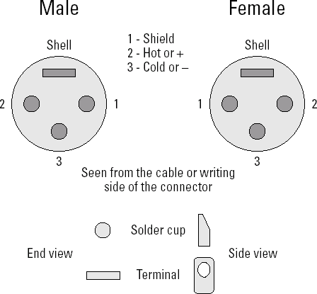
The XLR connectors seen in Figure 10-1 are professional quality. If you ever get to be a roadie for a band, you'll see plenty of these connectors on thick, black cables that plug into amplifiers and audio mixing boards. (You'll also fix a lot of them.) An XLR connector has three contacts and a heavy metal (no pun intended) shell. This combination makes it tough and electrically secure.
The ends of cables generally have female XLR connectors while equipment and wall plate connectors are male. (You will come across exceptions.) The shell is not electrically connected to any of the audio pins — it's for mechanical protection only. Having all of the electrical signals inside the connector means that it doesn't matter what the shell bumps into, such as another audio signal or a power cable that might cause noise or buzzing.
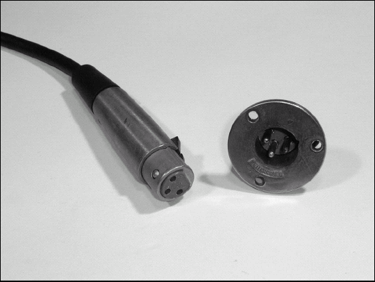
Figure 10-1. XLR connectors are the standard for professional and public-address system microphone and audio wiring.
The standard connection conventions are also shown in Figure 10-1. You should follow this convention for all your cables. If you discover a particular piece of equipment with another wiring convention, you can either change the equipment or make a short adapter cable that moves the wires to their required new homes. By keeping all your cables consistent, it's easy to hook up a portable audio system without worrying about wiring conventions all the time.
Note
Balanced/unbalanced wiring: Audio wiring is called balanced, when neither one of the twisted-pair conductors is connected to ground; instead the wires are twisted together to reject electrical noise and interference. They are surrounded by a shield braid or foil for further protection from noise. Unbalanced wiring uses ground as one of the conductors that makes up the complete circuit — often the outer shield. Coaxial cable is an example of unbalanced wiring.
Warning
Do not directly connect either of the signal conductors in a balanced system to ground. This unbalances the formerly balanced signals and usually results in hum or distortion.
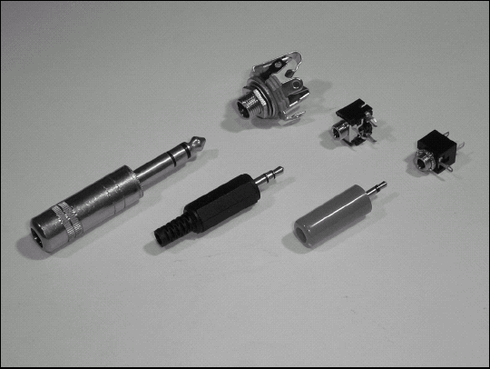
Also known as RCA connectors, these very common connectors shown in Figure 10-2 are found on patch cables for audio and video. The back of a DVD player or stereo receiver has quite a number of phono jacks for inputs and outputs, grouped together by function (such as CD IN, VIDEO 1, and so on). Each carries a single (or mono) channel of audio or a single channel of video. This task shows you how to install a new phono plug on an audio or video cable that plugs into one of these jacks.

Tip
Patch cables for audio and video are so inexpensive that unless you're making a special custom cable or need to repair a cable quickly, it's much more cost-effective simply to buy new cables. The next time you're in an electronics store, buy a few spares so you're never caught without spare or replacement cables.
Warning
It's natural to want longer patch cables, but beware: Cables longer than about 15' place loads on equipment inputs and outputs that can reduce high-frequency response, making audio sound muffled or video to be blurry and jumpy. For longer separations of audio connections, use low-impedance line-level inputs and output. For video, use coaxial cable and 75-ohm inputs and outputs.
Phone plugs (as shown in Figure 10-3) are descendents of the connectors used at telephone switchboards (see "Installing a Telephone Plug" in Chapter 7) and are still common in audio equipment and circuits today. Along with the ¼″ model, there are also miniature 3.5 mm and subminiature 2 mm versions. All three are available in stereo (3-wire) and mono (2-wire) versions. The common standard is for the connector's tip contact to carry the left audio channel and the ring contact the right audio channel. The sleeve is a common ground for both channels.
Most of the connectors in this chapter are for cables that carry audio signals. Another type of sensitive signal carried by cables is a DC voltage or current that represents the value of some measurement. These signals also need protection because noise or disruption degrades the accuracy of the measurement.
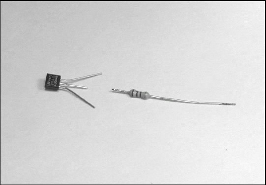
The temperature sensor in the task "Constructing a Temperature Sensor" later in this chapter (an LM34C) is an IC built into a small plastic package (known as a TO-92) of the type that usually holds a single transistor. The internal circuit is simple, and the small package helps the sensor respond quickly to changes in temperature. Download the data sheet for the LM34C at www.national.com/ds/LM/LM34.pdf#page=1 to use as a reference.
Note
Sensor: A device that measures the value of some physical parameter (temperature, flow, level, brightness, and so on) and outputs the measurement as an electrical signal, usually voltage.
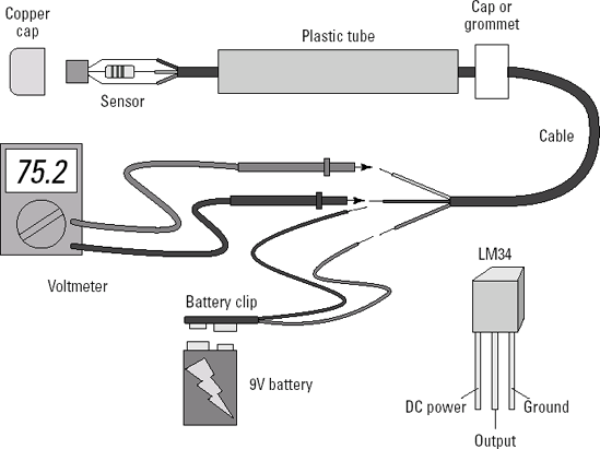
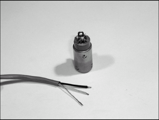
The circuit for the temperature sensor in Figure 10-4 is very simple. All of the internal circuitry (see the Block Diagram at the end of the downloaded LM34C data sheet) is contained inside the TO-92 package. The LM34 only has three connections; power, output, and ground. To output a voltage representing temperatures from +5 to +300° F it can be powered by voltages as high as 35V DC. (Special circuits are shown in the data sheet to allow measurement of temperatures below zero degrees.) You can read the output voltage of the circuit with a multimeter and interpret it as a temperature: 1.00V = 100° F.
The only non-obvious part of the circuit is the 2.2 kΩ resistor at the output connection. This is a decoupling resistor that isolates the sensor from the small capacitance created by the cable connecting the sensor to the voltmeter. (See "Capacitive Loads" on page 6 of the IC data sheet for more information.) The IC is very small; its output circuit can't charge up that small capacitance and still keep the voltage steady. Without the resistor, the output becomes unstable, jumping back and forth as the sensor output circuit tries to maintain a steady output voltage but can't quite keep up. This creates a galloping effect as the output voltage swings back and forth a volt or two. The resistor limits the amount of current the output can pump into the cable — and that calms things down so the output can maintain a steady voltage at the cost of a very small voltage drop caused by the resistor. (It won't hurt the sensor to be operated without the resistor, so feel free to try it and see what happens!)
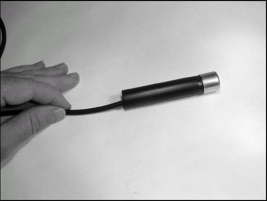
In this task, I assume that you've been given a bad microphone cable with a standard XLR connector. You'll disassemble, check, repair, and reassemble the cable and connector. In the process, you'll become familiar with this reliable, sturdy connector and the standard wiring conventions for it.

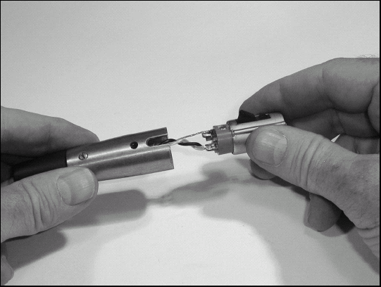
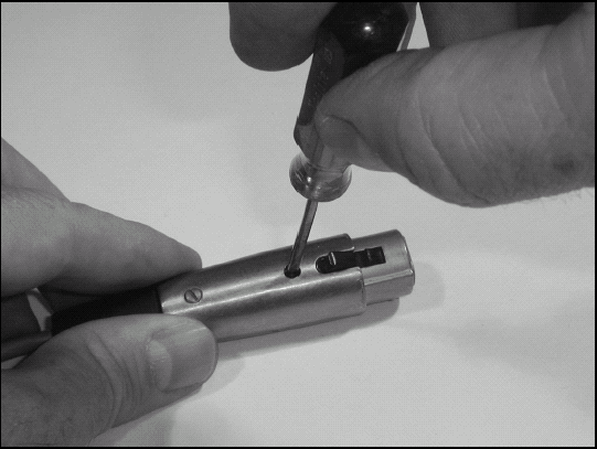
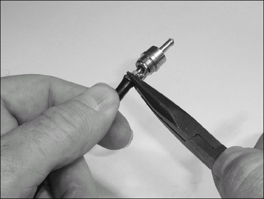
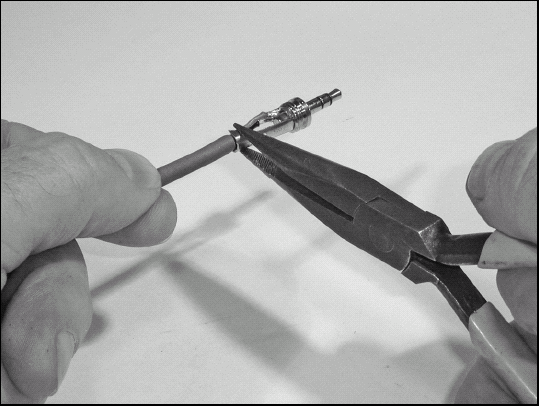
Disassemble the old connector by screwing in the small set screw located near the front of the connector. Turn the screw as if you were loosening it (counter-clockwise) and the screw will move farther into the central plastic body of the connector. If your connector has cable clamp setscrews (usually two) at the rear of the connector shell, loosen but do not remove them.

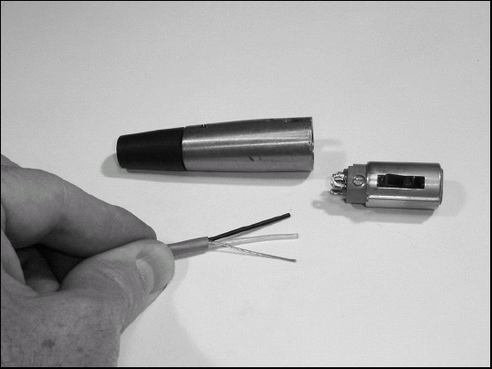
When the screw head has withdrawn past the inside surface of the metal shell (you can see this by looking into the set screw hole) gently pull the back portion of the connector out of the front portion while rocking it back and forth. This will expose the contact terminal block of the connector. Push the back part of the shell farther along the cable until the connections are completely exposed. There may be a plastic insulating sleeve around the terminals. Push that back along with the shell. Keep the shell on the cable.
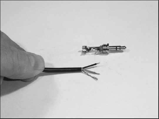
When you are repairing a cable, this is the point at which you can inspect the connections between the wires and shield and the terminals. A bad cable will usually have one or more connections completely broken, have only one or two strands of wire left connected, or have a short circuit between two terminals from loose strands of wire.
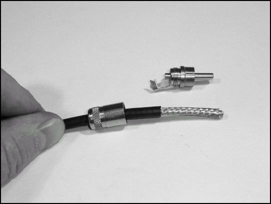
On a piece of paper, write down which color of wire is soldered to which terminal. Then unsolder the wires from the terminals; set the block with the terminals aside if you're going to reuse the connector. Cut off the end of the cable completely, about an inch back from where the jacket ended. This also removes any worn area of the shield. If you're going to side of the connector use a new connector, replace the rear shell, strain relief, and any insulating sleeve with those from the new connector.
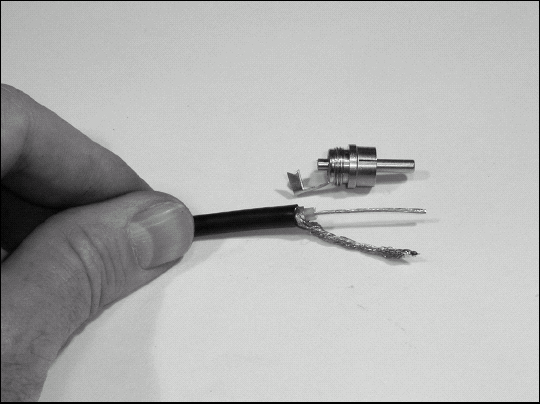
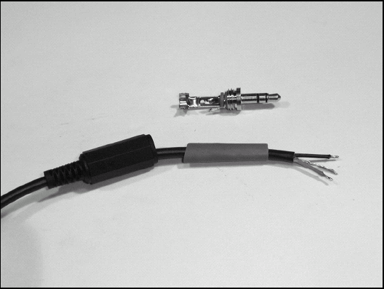
Remove 1" to 1 ¼″ of jacket, being careful not to nick the braid or foil. Trim away any string or fiber filler in the cable. If the shield is foil, peel back and remove the foil while leaving the shield wire intact. If the shield is braid, twist the strands together to make one fat wire and tin the end to keep it together.
Strip ¼″ off each wire and tin.
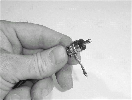
If you are reusing a terminal block, remove all excess solder and wire bits from the terminals. For a new connector tin the terminals.
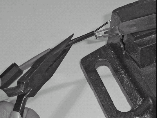
Connect each wire, including the shield wire or shield, to the terminals as noted in Step 4. If present, slide the insulating sleeve back over the terminals. If your connector had the shell terminal (the large, unnumbered terminal) jumpered to pin 1, make that connection by pulling the shield wire or braid through the shell terminal to pin 1. Solder the shell terminal first, then pin 1.

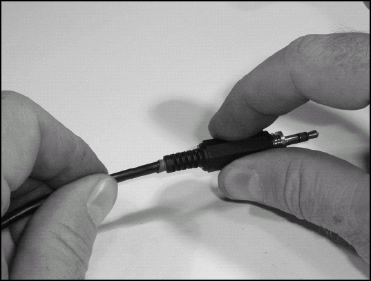
Pull the cable through the back of the shell to seat the terminal block into the shell. You may have to turn the shell in order to fit the cable in with the right orientation.

Slide the front part of the connector back on and align the access hole in it with the screw hole for the set screw.
Turn the set screw to the left so that it backs out of the terminal block into the shell, but no farther than its surface being flush with outer surface of the shell. If there are any clamps at the back of the connector, tighten them now.
Check continuity from end to end of each contact to be sure the cable is wired properly: Both ends should be exactly the same, and there should be no short circuits between contacts.
Note
If the new cable has the same problem as the old cable, you probably have a bad connector on the audio equipment. Swap in a different cable and see if it acts any differently. If not, the equipment connector is probably bad. Otherwise open up your cable and check again.
Phono plugs and cables are widely used for audio, power, control signals, and even low-power transmitting equipment. It's quite easy to install and repair them — a good thing since they are not particularly sturdy. In this task you'll install a phono plug on a shielded audio cable, typical of most wiring that uses phono connectors.
Trim the end of the cable and strip away an amount of the cable jacket equal to the distance from the tip of the connector to the forward edge of the strain-relief wings. If the phono connector has a removable shell, slide it on to the cable now.
Tin a short section of the phono connector body halfway between the strain relief wings and the connector body. This is where the cable shield will be connected.

If the cable has a braided shield, comb out the strands. Twist the shield wires together to make a single wire. Tin one end to keep it together. If the cable has a foil shield, remove the foil along with the jacket and use only the single-shield wire. Strip and tin the cable's center wire, leaving enough insulation to prevent short circuits to the shield.
Insert the center wire into the phono connector so the wire just barely sticks out the front of the center pin and the end of the jacket is just forward of the strain-relief wings. Make sure there are no loose strands of wire that might cause a short circuit to the connector shell.

Solder the center conductor to the tip of the metal pin and trim away any of the wire sticking out past the pin. It helps to have the phone connector tilted slightly downwards so that solder will stay close to the connector's tip. Solder on the outside of the pin may increase the pin's diameter, making it hard to insert into the socket. Carefully shave off excess solder with the knife. Clean any solder flux off of the pin with a knife or brush.
Bend the shield wire so it lies on the tinned area of the connector. Trim away any excess wire. Solder it to the connector.

Wait a minute or so for the connector to cool. Use needle-nose pliers to capture the jacket of the cable in the strain-relief wings. Do not force the wings into the jacket; just clamp the cable. Trim any loose strands of braid wire.
Reattach the connector shell and use a voltmeter to measure resistance of the cable between the center pins and between the metal bodies — both should show short circuits. Check between the center pin and the shield — that should be an open circuit.
Note
If your connector shows a short circuit between the center pin and connector body, the most likely cause is a stray strand from the center wire. You'll have to unsolder the shield wire, unsolder the center pin to remove the cable, and check for stray strands or bits of solder. Leaving solder flux on the center pin can cause an erratic or non-connection when the connector is inserted into a mating socket. If the shield connection is erratic, the usual cause is a poor solder connection of the shield wire.
It's frequently useful to connect the headphone output of an audio source such as a radio or music player to the line-level stereo input of a computer sound card or recorder. Both of these devices usually have a 3.5mm miniature stereo phone plug as their audio connector. In this task you'll learn how to make the appropriate cable to make the connection. You can use this skill to make all kinds of audio cables.
When you're making a stereo audio patch cable, you must use shielded twisted-pair cable that is intended for stereo audio signals. Audio cable has two separate wires surrounded by a metal shield, which is itself surrounded by the cable's outer jacket. (You can also use dual-pair cable that has separate wire/shield pairs for each channel.) Do not use unshielded cable because it exposes the signal wires to interfering signals and other noise. Cable with a braided or twisted shield made of many fine wires is preferable for patch cables because of its flexibility. An alternative style has a shield made of foil, with a separate wire in contact with the foil. The wire can be soldered to connectors. Either will do, although the foil-shielded cable is stiffer.

Start by unscrewing the connector's plastic or metal shell (also known as a backshell) to disassemble the connectors. Place the connector in your vise and tin the tip and ring contacts with solder. (See Part I for information on soldering.) Tin the sleeve contact just in front of the cable strain relief wings.
Use the wire strippers or knife to remove ½″ of the cable jacket. Try not to nick the thin shield wires. Remove the shield foil, if present. If the shield is braid or fine wires, Twist the shield wires together to make a single twisted wire.
Strip ⅛″ from each audio wire. Tin the stripped end of both wires, but leave the shield or shield wire untinned.
Cut two 1" pieces of heat-shrink tubing that will fit the cable jacket snugly when shrunk. (The tubing's unshrunk inside diameter should be about 50-100% larger than the jacket. Slip one piece over the end of the cable.
Slip the shell of the connector over the end of the cable, oriented so it will screw back onto the connector. Double-check to be sure you have it right; an error will require removing the connector to turn the shell around.
Place the cable in position and determine where the shield wire will touch the tinned area of the sleeve contact. Tin that portion of the shield wire and clip off the rest.

Prepare to solder the wires and shield to the connector in this order: shield, ring, tip. It will not be necessary to apply a lot of heat because both the wire and connector contact are already tinned. Place the tinned shield wire against the tinned area of the sleeve contact while holding (gently!) the insulation of the wire with the needle-nose pliers. Apply the soldering iron's tip; when the tinned area of both wire and connector have melted, withdraw the iron, holding the shield wire steady until the solder solidifies. Now hold the end of the ring wire to the connector's ring contact and do the same; repeat this procedure with the tip wire and contact.
Wait for the connector to cool, then slide the heat-shrink up the jacket until it hits the connection of the shield wire and sleeve. Shrink the tubing onto the jacket.
Use the needle-nose pliers to squeeze the strain-relief wings so that they capture the heat shrink and cable jacket. They should not cut into either the heat-shrink tubing or the jacket.
Screw on the shell. Repeat for the other end of the cable, if necessary.
Test the cable with a continuity checker or multimeter with resistance scale. Check tip-to-tip, ring-to-ring, and sleeve-to-sleeve — all should show low resistance of less than 1 ohm. Then check tip-to-ring, and sleeve-to-ring — all should show an open circuit (keep your fingers off the electrical contacts!).
Note
On your first attempt, you may find it difficult to handle the small wires with the pliers without melting the insulation from the heat of the solder. This is a skill that takes a little practice! Learn to use the minimum amount of heat and the shortest soldering duration necessary so the insulation of the wires doesn't get so hot. If your resistance checks show short circuits between contacts on the same connector, try using less solder — a little goes a long way!
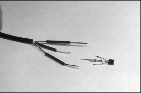
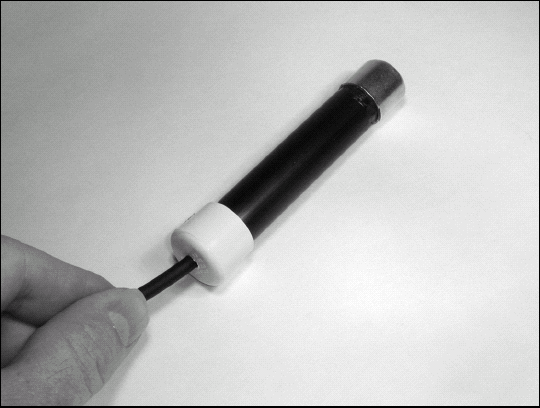
We'll build the sensor into a small metal tube, power it with a 9V battery, and read the temperature with a voltmeter. The sensor itself is mounted in a metal tubing cap so it will quickly reach the same temperature as the probe's surroundings. A plastic tube protects the assembly and allows the probe to be positioned without conducting heat toward (or away from) the sensitive sensor.
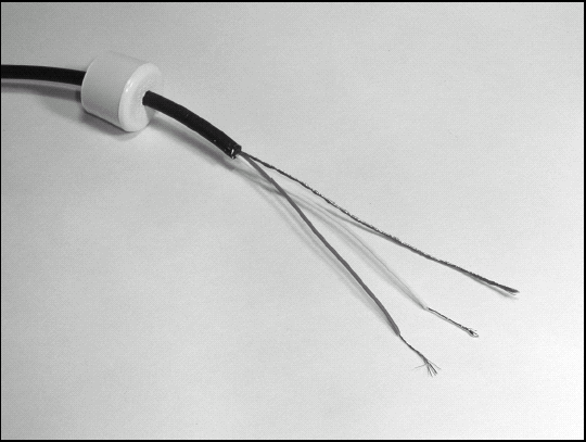
Prepare the probe's output connections by removing 3″ of the jacket from the cable and any unused wires. Strip the three wires about ¾″. (If you are using cable with a shield, use the shield as the ground connection by removing any foil or twisting the shield wires together and tinning the end.) Tin the stripped wire you will be using as the signal output wire. Leave the other wires untinned. Slide the grommet on to the cable. (If you are using a plastic cap, drill a small hole in it and slide it on to the cable.)
Twist the bare end of the 9V battery clip's black wire together with the wire you'll be using as ground for the LM34. Solder them together.
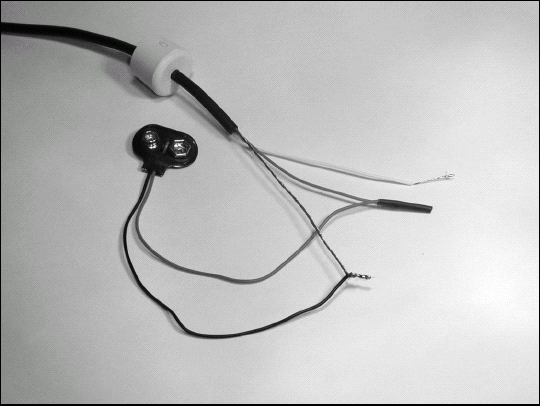
Twist the bare end of the 9V battery clip's red wire together with the wire you'll be using as power for the LM34. Solder them together, then place a short piece of 3/16" heat-shrink tubing over the connection and shrink it on to the wires.
On the other end of the cable, remove 2″ of the jacket and trim away any unused wires.
By now the epoxy should be cured so check to be sure that the LM34 is securely mounted in the cap. If so, cut the center lead of the LM34, leaving ½″ extending from the body of the sensor. Lightly tin that lead.
Cut off one lead of the 2.2 kΩ resistor ¼″ from the body of the resistor and lightly tin that lead.

Hold the resistor with needle-nose pliers with the short tinned lead next to the LM34's tinned center lead. Melt a small ball of solder on the tip of the soldering iron and touch it to both leads. The solder will flow onto both leads. Remove the iron and hold the leads steady for a few seconds until the solder cools. The soldering step should only take a couple of seconds — don't hold the iron on the leads very long.
Trim the remaining lead of the resistor to ½″ long and lightly tin it. Also tin the two remaining leads of the LM34.
Trim the leads of the cable to match the lead lengths of the LM34, remembering which lead will connect to which LM34 pin. (Review the IC connection drawing in Figure 10-4 earlier in this chapter to be sure.) Strip each lead about ¼″ and tin.
Cut three 1 ″ pieces of ⅛″ heat-shrink tubing and slide them on to the wires protruding from the cable jacket.
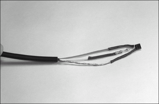
Solder each wire onto the appropriate lead of the LM34. After each wire is soldered, slide the heat-shrink tubing over the connections. Slide the tubing on the power and ground leads all the way up to the LM34 body and shrink the tubing.
Test the sensor before final assembly by connecting a 9V battery to the battery clip. Use a voltmeter to measure the output voltage between the ground and output wires. If room temperature is about 75° F, the output voltage should be a steady 0.750V DC plus or minus 30 mV (0.030V). If the sensor is working, disconnect the battery and voltmeter. If not, trace your wiring and be sure you have the proper connections and that none have come loose at the LM34.
Clean the inside of the copper tubing cap and place it open side up on your workbench. Mix a small amount of epoxy using a single drop from each tube. Put the drop into the center of the cap.

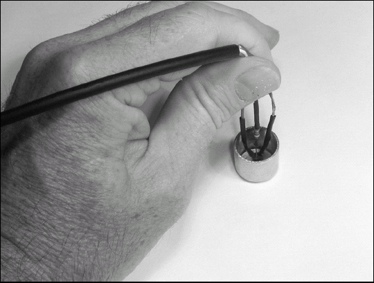
Place the LM34 into the epoxy with its output leads sticking straight up and the base of the LM34 pressed firmly against the inside of the cap. Hold the LM34 steady until the epoxy cures.
If you intend to place the sensor into liquids, epoxy the cap to the tube. Mix another small batch of epoxy and glue the plastic tubing to the cap after threading the cable through the tubing. It doesn't matter whether the cap goes inside or outside the tubing. If the tubing fits over the outside of the cap, leave about half of the cap exposed for better thermal exposure.
After the epoxy sets, slide the cap or grommet down the cable and seat it on the open end of the plastic tube. If the cable fits snugly in the grommet, you're done. If not, wrap the cable with a few turns of electrical tape, and reseat it — or you can epoxy the cable into the grommet.
Use the sensor as in Step 12. Take care not to get liquids into the plastic tubing — and don't heat the sensor past the point where the plastic tubing will begin to melt.