Most electronics books and how-to guides spend a lot of time inside the box, but how do you get the box hooked up? Taking a look behind any stack of electronic stuff and what do you see? Wires and cables! On each end of each wire and cable is a connector or some terminals. As a successful electronic-er, you'll need to know how to select, create, maintain, and repair those simple-but-crucial items that get the signals and the juice where they need to go. In this chapter, we take a look at several common wire-cable-connector combinations. Dozens more are possible, but if you learn these basic techniques, you'll be able to figure out others easily.
One consideration that applies to all such combinations: Use the right wire or cable. If you're working with digital data or audio signals, you'll need to use a data or audio cable if you want the data to flow fast and the audio to remain crisp and clear. If the cables and connectors are important to making a good quality connection, the equipment manufacturer will specify what to use; usually in an operating or user manual.
As electrical appliances and machines became widespread, electricians and engineers tried a lot of different ways to make reliable connections in power and control circuits: screws, soldering, and clamps. They worked, but were often time-consuming. Finally, someone hit upon the idea of capturing a wire inside a tube by collapsing or crimping the tube. They found that if the crimps were made correctly and securely, the resulting connection was just as reliable as the traditional methods. Today, crimped-on terminals and connectors of all sorts are used in nearly every field of electronics. Each type of crimp is a partnership between a terminal or connector and a special tool that crimps the connection just so. Let's meet the three most common varieties.
Crimp terminals are the most common method of making connections for control and DC power wiring. You'll find crimp terminals in your car, in your home, and many appliances. Each terminal makes a connection for a single wire that is stripped and inserted into the terminal, then attached by crimping. Being able to install these terminals properly is important to prevent intermittent connections. Poor connections carrying high currents can also get hot enough to become a fire hazard. It's simple to install these terminals, however.
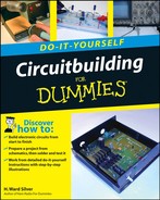
There are three common terminal styles seen in Figure 7-1; ring, fork, and spade. Ring and fork terminals are intended to be attached to screw terminals, usually on an array of terminals called a barrier strip or terminal strip. Ring and fork terminals are specified by stud size (the diameter of the screw terminal they fit — #6, #8, #10) and by wire size (the thickness of the wire that they can be crimped to hold).
Tip
There are a number of variations on each terminal style. Enter "crimp terminals" into an Internet search engine to find dozens of catalog links to terminal vendors with complete drawing and style information. Appendix A contains links to the Web sites of several distributors of electronic components, including terminals.

Figure 7-1. Crimp terminals attach to the end of individual wires and are made to attach to screw terminals or to snap together.
The various crimp terminals differ in the following ways:
Ring terminals have a hole through a flat terminal. A screw is inserted through the hole so that the terminal can not be removed without also removing the screw or nut. This prevents a ring terminal from pulling out from under a screw due to vibration or tension.
Fork terminals form a 'Y' that fits around a screw terminal and are held in place by the clamping force from the screw. They are used when vibration or tension are not expected to cause the terminal to loosen.
Spade terminals come in male and female versions, also called quick-disconnects because they can be inserted and pulled apart without tools.
Butt-splice terminals are used to permanently join two wires together end-to-end. They consist of a single tube that is crimped on each end to capture the two wires.
Terminals are available in insulated and non-insulated versions, with the insulation color signifying what size wire fits the terminal. Table 7-1 shows the three common terminal colors and sizes.
Tip
Using the terminal size required for the wire diameter being used is important to ensure a proper, low-resistance crimp in which the wire is completely captured by the terminal and will not work loose. Using terminals that are too large or too small will result in an unreliable connection.
Warning
Do not use crimp terminals with solid wire — and do not use pliers or other tools to crimp terminals. Solid wire is not captured firmly enough by a crimp; it will pull out or work loose. Solid wire may also eventually break at a nick or sharp terminal edge. Pliers and other such tools only deform the terminal body and don't apply enough concentrated force to properly capture the wire.
Industrial and commercial terminal installers use special tools that are made to make hundreds of crimps precisely the same. Those tools are too expensive for the hobbyist. By far the most common terminal crimping tool used by civilians is the hand-operated crimper-stripper shown in Figure 7-2. Although the crimper looks like a pair of pliers (and may have plier-type jaws at the tip), this tool can make a very satisfactory crimp if used properly: Be sure to use the correct position, orient the terminal properly, and squeeze until the crimp is well formed.

The keys to making a good crimp are threefold:
Match the wire and terminal size.
Strip the wire properly.
Crimp the correct side of the terminal.
Figure 7-3 shows how the wire is inserted in the terminal and how the crimp captures the wire. Take note of the following in the figure:
The tabs below the electrical contact area are rolled up to form the terminal's hollow barrel.
The area of ring and fork terminals that makes electrical contact with the screw or nut stays flat.
The cross-section of the barrel before and after a crimp shows how the wire is captured and solidly held.
In a proper crimp, the bottom non-seam side of the crimp tube is collapsed to form a short tab that presses the strands of wire against the inside of the rolled portion of the crimp tube. A properly crimped terminal captures all strands of the wire and the terminal wall tightly so as to resist corrosion and to provide high pull-out strength.

If the seam side of the crimp tube is crimped, the walls of the tube flare apart, greatly reducing the terminal's gripping strength. Terminals crimped in this way will usually fail because the wire pulls out, or because the resulting connection is relatively poor and eventually fails from vibration, heating, or corrosion.
Take a close look at your crimping tool. Each stripping position is labeled with the wire size. Find the position for your wire and practice stripping just enough of the insulation off the wire. The bare wire should protrude no more than 1/16" from the barrel of the terminal as shown in Figure 7-4. If your stripper doesn't strip the wire cleanly, move to the next smallest size and try again. Different types of insulation require different depths of cutting by the stripping edges.
Look closely at the crimping part of the tool. The crimping positions are located between the pivot and the handle. They are labeled by terminal size and may have colored dots to indicate the position for each size of terminal. Note which side of the tool the crimping tab is on.
Practice crimping a couple of terminals without any wire in them. Place the terminal in the proper crimp position for its size. The crimping tab should press on the terminal from the non-seam side of the crimp tube. Figure 7-5 shows how the terminal should be oriented — so the crimp tab is in the middle of the barrel.
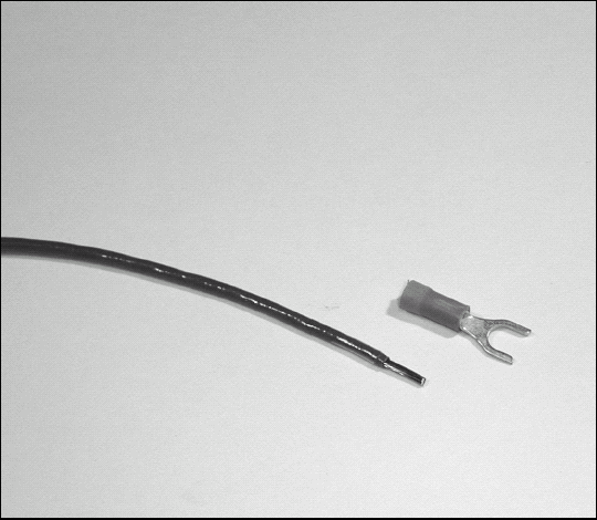
Figure 7-4. Wire should be stripped just far enough for the bare wire to barely protrude from the barrel of the terminal. If the wire and terminal sizes are matched, the wire insulation will not enter the barrel.

Figure 7-5. Place the crimping in the middle of the terminal's barrel on the opposite side of the barrel's seam.
Now squeeze! As soon as the crimp tab punches into the crimp tube, you can let up. You don't have to strangle the tool! Use a magnifier to look into the crimp tube so you can see the indentation that captures the wire. Look at the back of the terminal to see the clean dimple in the insulation surface (as shown in Figure 7-6). If you didn't make a clean crimp, try again until you feel comfortable with the tool and terminals.

Used to install telephone connectors on what the telephone industry calls "modular cable", the modular-plug crimping tool (shown in Figure 7-7) is a cousin to the tool used for crimp terminals shown in Figure 7-2. It's used in fundamentally the same way: You strip the cable, place wires in the connector, insert the connector into the tool, and squeeze. As the handle is squeezed, a row of tabs press on the modular plug's contacts, forcing their sharp teeth through the insulation and into the wire itself. This connector design is engineered to be simple, inexpensive, and surprisingly strong.
Telephone modular cables and handset cables have two or four wires surrounded by a flat plastic jacket so all the wires are in a row. Connectors that go into a telephone wall jack and the phone itself have the model number RJ-11. They generally have four contacts, although you will occasionally encounter 6-conductor versions that support three separate telephone lines (see the sidebar "Making the Right Call on Telephone Cables"). The cords that connect handsets to phones have a narrower plug called an RJ-10 or RJ-H. A drawing showing the workings of modular connectors is shown in Figure 7-8.

Figure 7-7. This inexpensive modular-plug crimping tool is used to install modular plugs on telephone modular cable and handset cords.

Figure 7-8. Common modular plugs are crimped onto flat telephone modular cable. Be sure to orient the cable so the right color wire is connected to the right plug contact.
Table 7-2. Modular Cable Color Codes
Connector pin number | RJ-11 function | RJ-12 function | Old color code | [b]New (UTP) color code |
|---|---|---|---|---|
| [a] | ||||
| [b] | ||||
1 | None | Line 3, tip | [a]White | [a]White/green |
2 | Line 2, tip | Line 2, tip | Black | White/orange |
3 | Line 1, ring | Line 1, ring | Red | Blue/white |
4 | Line 1, tip | Line 1, tip | Green | White/blue |
5 | Line 2, ring | Line 2, ring | Yellow | Orange/white |
6 | None | Line 3, ring | [a]Blue | Green/white |
[a] Not present in 4-wire cables. [b] Second color is the stripe color. | ||||
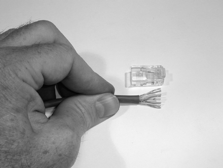
The RJ-45 plugs used for computer network cables are similar to telephone modular plugs and have eight contacts instead of four or six. The crimping tool for RJ-45 plugs is very similar to a telephone modular crimping tool. Figure 7-9 shows RJ-45 plugs and a suitable crimping tool. I prefer the metal crimping tool because more contacts are being pressed into the wire at once. Lightweight, plastic crimping tools will work if you pay a little extra attention to detail.

Figure 7-9. Similar to telephone modular connections, the RJ-45 modular plug is used for computer network cable. The crimping tool is similar to that used for the smaller telephone connectors.
Determine whether you need a straight-through or a crossover cable:
If you're connecting a computer to a network device such as a hub, switch, router, or DSL gateway, you will almost always use a straight-through cable. Check the equipment manual to be sure.
If you're connecting two computers directly (or a computer directly to some other device that's made to be connected to a hub or switch), then you need a crossover cable.
Warning
If you use the wrong type of cable, transmitting circuits will be connected to transmitters and receivers to receivers. (Oops.) This won't cause electrical damage, but no one will be listening or talking correctly and the connection won't work.
Network cable looks like telephone modular cable, but it's not the same. Network cable is a special type called CAT5 UTP (Unshielded Twisted Pair) in which there are four pairs of wires, each pair twisted together separately from the others. Each network signal is carried by one pair of wires. Table 7-3 shows the standard color code for network cables. A discussion of network connector wiring with color pictures is available online at www.incentre.net/incentre/frame/ethernet.html.
There are two ways to make a straight-through cable; use the 568A color code on each end or use the 568B color code on each end. Either will work, but you must use the SAME color code on EACH end.
There is only one way to make a cross-over cable: use the 568A color code on one end and the 568B color code on the other end.
Table 7-3. Network Cable Color Codes
Pin number | 568A Wire color[a] | 568B Wire color[b] |
|---|---|---|
| [a] | ||
| [b] | ||
White/green | White/orange | |
2 | Solid green | Solid orange |
3 | White/orange | White/green |
4 | Solid blue | Solid blue |
5 | White/blue | White/blue |
6 | Solid orange | Solid green |
7 | White/brown | White/brown |
8 | Solid brown | Solid brown |
[a] - second color is the stripe color [b] -for crossover cables, connect the other end using the straight-through color code | ||
A COM port on your PC is an RS-232 serial data interface. Most desktop PCs have one or two, while a laptop PC will have just one at most. The predecessor to USB and Firewire, RS-232 was the standard connection between computers and modems and data terminals for many years. Even though it's being replaced by faster and less expensive technology, RS-232 interfaces are still very common. The task "Making an RS-232 Data Cable" later in this chapter shows you how to connect a 9-pin standard version of the RS-232 connector.
Figure 7-10 shows examples of the two types of DB-style connectors used with RS-232 connections. (There are other DB-style connectors, but they're not often encountered.) The DB-9P has 9 male pins and the DB-25P has 25 male pins. DB-9S and DB-25S connectors have female sockets instead of pins. Connections to the pins can take three forms:

The RS-232 interface has two data lines, RxD (receive data) and TxD (transmit data), a ground connection, and a set of control signals to manage the flow of data between the devices. Table 7-4 shows the common control signals and the pins to which they are assigned on DB-9P and DB-25P connectors. (DB-9S and DB-25S have slightly different pin assignments.) You'll need a magnifier and good lighting to locate the pin numbers on the back of the connectors. Most equipment doesn't use many of the control signals — and may not use any — even though the RS-232 cables you buy in the store may have every pin connected.
Table 7-4. RS-232 Signal and Pin Assignments
Signal | DB-9P Pin | DB-25P Pin |
|---|---|---|
Signal Ground (GND) | 5 | 7 |
Transmitted Data (TxD) | 3 | 2 |
Received Data (RxD) | 2 | 3 |
Data Terminal Ready (DTR) | 4 | 20 |
Data Set Ready (DSR) | 6 | 6 |
Request To Send (RTS) | 7 | 4 |
Clear To Send (CTS) | 8 | 5 |
Carrier Detect (DCD) | 1 | 8 |
Ring Indicator (RI) | 9 | 22 |
There are two common configurations of data and control signals:
3-wire RS-232: This is the simplest, consisting of GND, RxD, and TxD. No control signals are used and the data flow is managed by software in each device.
5-wire RS-232: This configuration uses the 3-wire signals plus Request To Send (RTS) and Clear To Send (CTS). No, there won't be a quiz on this! But you do need to know what to look for in the equipment manuals to tell you how many wires to use.
Tip
In computer networking, a cable that allows two computers to talk directly without any intervening network equipment is called a crossover cable. (See the task, "Making a Computer Network Cable.") A cable that provides the same function between RS-232 interfaces is called a null modem cable because it replaces the pair of modems that would normally be used for computers to talk to each other using RS-232.
Buy a bag of fork, ring, or spade terminals from an automotive parts or electronics store. These stores will also have combination stripper-crimpers for a few dollars. Make sure the terminals are the right size for the wire you have at home or buy some wire to go with the terminals.

Strip a piece of wire about 5/16. Insert the stripped wire into the crimp tube until the insulation hits the end of the crimp tube. The stripped end of the wire should just be visible at the other end of the crimp tube, extending no more than 1/16.

Holding the wire in one hand, open the crimping tool with your other hand, and guide the terminal into the proper crimp position. Remember to keep the terminal oriented properly for the crimp tab.
With the wire in the terminal and the terminal in the jaws of the crimper, do one last inspection and when you're ready, give the crimping tool a firm squeeze until you feel the crimp tab "hit bottom" and stop moving. Release the handles of the crimper and remove the terminal.

The terminal should be firmly attached to the wire. Give the wire a good yank to confirm that it won't pull out. If it does pull out, you need to make a better crimp. Check the placement of the crimping tab and whether you had enough wire stripped and in the crimp tube.
Tip
Practice using different sizes of wires and terminals until you can install a terminal quickly and properly.
Note
If the wire pulls out of the terminal — or seems to move around in the terminal when you pull or twist it — then the terminal wasn't positioned correctly in the crimping tool's jaws and needs to be replaced. Be sure that the crimp tab is positioned over the barrel and not just over insulation. Also be sure that you're not crimping on or near the seam of the barrel (see Figure 7-3). If you find that the electrical connection is intermittent or nonexistent, you may be pushing some of the wire insulation into the barrel, preventing the crimp from contacting the wire. Crimp terminals can't be re-crimped, so cut off the bad one and put on a new terminal.

Whenever you connect electronic equipment to a source of DC power, you must consider protecting the power source and the equipment from fire hazards caused by excessive current. If the power source is capable of supplying more than a few watts of power, add a fuse in the equipment power leads. Batteries, particularly vehicle batteries, and large DC power supplies, can cause significant damage in the event of a short-circuit or circuit failure! (The author knows this from personal experience ...)
If your equipment doesn't already have an internal fuse, it's easy to add one externally by using an in-line DC power fuse kit. In-line fuse kits are used to add a fuse to power leads for equipment that doesn't have an internal fuse (like the one shown in the following figure). Kits are available from electronic parts suppliers and auto parts stores. Fuse holders are available for either glass-cartridge fuses or automotive blade-style fuses. Be sure that the kit is rated to handle the amount of current you need.
The fuse kit is manufactured with a loop of wire connecting the two terminals of the fuse holder. Cut the fuse kit wire in the middle of the loop (or wherever it's most convenient for your installation). Strip the ends of the fuse kit wires and the power lead wires. (The coil of wire in the figure represents the equipment power leads in this task and is not part of the kit.)
Install a butt-splice terminal, joining each stripped end of the power leads and the fuse kit's leads. Make sure that the terminal is solidly installed, as described in the previous task.

Install a fuse in the fuse holder. Done!
Note
If you get the fuse holder installed, but power isn't getting to your equipment, double-check the fuse itself. Use a magnifying glass to inspect the fuse or measure its resistance from end-to-end with a meter (see Part IV for help). If the fuse is good, check the butt-splice crimps. Finally, make sure the fuse holder is assembled properly.
Isn't it amazing how often telephone cords are so often just inches too short? In this task, you get a crack at repairing or making your own cords — as long as you want! The same procedure can be used for telephone handset cords.

If you're repairing a bad cable, cut off the plug at the end, leaving a clean end with the cut directly across the cable. For new cables, just be sure that the end of the cable is a clean, square cut.
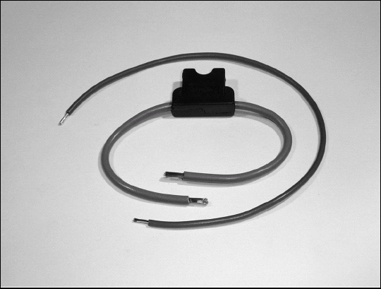
Use the strippers built into the modular crimping tool to strip the cable as follows: Insert the cable into the strippers until it contacts the built-in depth gauge stop. Squeeze the handles — and while you're holding firm, pull the wire out of the strippers. The jacket will come off and you'll be left with four (or six) wires in a row.

Insert the stripped end of the cable into the plug, taking care that the wires go in the positions with contacts. Double-check to make sure you have the right colored wire in the right position. Looking down on the side of the connector with the locking tab as show, the colors should read (left to right) black-red-green-yellow. The jacket of the cable should extend into the back of the plug.
Insert the plug (with cable inserted) into the modular crimping tool until the locking tab on the plug snaps out, just as it does when you're plugging the cable into a wall jack.
Squeeze the handles on the tool until they stop moving together. This doesn't require much force; a firm squeeze will do the job.

Remove the plug from the crimping tool by pushing the locking tab toward the cable and then pulling the plug out of the tool. Give the plug a close visual inspection. You should see the teeth of the end contacts disappearing into the wire insulation. Give the cable a light pull to be sure it won't come out of the plug. If you're making a complete cable, repeat these steps for the other end of the cable. Otherwise try the cable with the phone!
Note
If the phone doesn't work with the new cable, double-check your color code to be sure the right wire is at the right contact position. Do a sanity check by replacing the new cable with a known good cable, if possible. If the phone doesn't work with that cable either, the problem may be in the wall jack, which is described in the next task.
Sometimes telephone wall jacks are damaged and need to be replaced. If you're remodeling or updating phone wiring, you will eventually have to replace the old-style telephone's wall-mounted screw-terminal blocks with modular jacks. This task shows you how to install the new jack — whether a replacement or a completely new jack.)

The following figure shows both the old and new type of telephone wall jack. An old-style telephone wall terminal requires the phone cable to be permanently attached to screw terminals. These should be replaced with new modular jacks. New jacks consist of a connector in the cover that snaps or screws on to a terminal block mounted on the wall. For more information about telephone wiring, take a look at the previous task. The Web site www.homephonewiring.com also has a lot of good information about your home's phonewiring system.

Start by finding the telephone service box for your house, opening its cover, and removing the modular plug as shown, disconnecting the line. Disconnect the line first will let you work on the wiring without any unusual electrical activity on your line or lines. If you're uncomfortable accessing your service box, the phone company will disconnect and reconnect for you, for a fee.

Unscrew the cover from the old block and remove the phone line cable (called premises wiring by the phone company) from all screws. Keep the wires apart. There are no dangerous voltages present, but shorting the wires together may cause the phone company to think you're dialing if you're working on a live line. If the old block has wires held between metal fingers, that is a punch-down block — just cut the wires at the fingers and re-strip them.
Remove the terminal block from the wall and replace it with the new jack's terminal block. If the screw hole is loose or has been damaged, use a plastic wall anchor to hold the new block firmly.

Reattach the premises wiring to the new jack's terminals, being careful to match the wire colors and the terminal colors exactly.
Reattach the cover of the new jack to the terminal block.
Return to the telephone service box, reconnect your phone line, and secure the cover. Now plug a phone into the new jack and make sure it works!
Warning
If you're a renter, the rental agreement may restrict what you can do to your home's phone wiring. Check first!
Note
If a phone doesn't work with the new jack, did you remember to reconnect the line at the service box? If so, double-check the terminal wiring to be sure the premises wire colors match those from the jack connector. If you were working on a live line, you may have confused the phone company's equipment as you disconnected and reconnected the wires. Wait for a few minutes to reset the line and try again. Try a different phone or change the phone-to-wall cable. If the phone receives a dial tone, but won't dial, the tip and ring connections (see the previous task) are probably reversed. If the phone is still completely dead, telephone-line testers are available from home-improvement stores and many electronics vendors. If all else fails, the phone company will come to your home and troubleshoot the problem (for a fee).
Start by reading through the sections earlier in this chapter on the modular crimping tool as well as the previous task, "Installing a Telephone Plug" to familiarize yourself with modular cable, connectors, and crimping tools. A computer network cable is a kind of big brother to telephone modular cables. In this task you'll learn how to make both kinds of computer network cables; straight-through and crossover.

Strip about 1" of the modular cable jacket using the crimping tool (if yours has a cable stripper) or by scoring the jacket with a sharp knife (don't nick the wire insulation). Untwist and straighten all the wires and arrange them in order of the straight-through column in Table 7-3.
Note
If the cable doesn't seem to work, give each plug a very close inspection, looking for both color code and complete crimping. Make sure that the pin-by-pin color code is correct. Each wire should be completely inserted into the plug. If there is any question, cut the connector off and start over. Cable checkers are available at computer-supply stores and electronic vendors, but such a tool may not be a good investment unless you're planning on making a lot of cables. Computer shops can usually check cables, too.
Trim the wires square with the end of the jacket and long enough (about ½″) so when the cable is inserted into the RJ-45 body, the cable jacket is also inside the plug's body.

Insert the wires into the RJ-45, making sure the wire order is correct. Seat the cable firmly to be sure all wires are all completely inserted. It may help to look at another network cable to confirm that you're doing it right.

Insert the plug into the crimping tool and squeeze the handles until they meet or hit a stop.
Remove the plug from the crimping tool by pushing the locking tab towards the cable and pulling the plug out of the tool. Give the plug a close visual inspection. You should see the teeth of the end contacts disappearing into the wire insulation. Give the cable a light pull to be sure it won't come out of the plug.
Make the other end of the cable in the same way. Double-check to be sure that you are looking at the connector in the same orientation on both ends of the cable and that you've positively identified pin 1 on both according to the drawings. If you're making a straight-through cable, arrange the wires in the plug using the straight-through column of Table 7-3. If you're making a crossover cable, use the crossover column of Table 7-3.
In this task, you're going to make a 3-wire DB-9P RS-232 cable and add jumpers between two sets of the four control signals; RTS to CTS (pin 7 to 8) and DSR to DTR (pin 4 to 6). This is a common trick used by manufacturers to let software do the heavy lifting of data-flow control while at the same time keeping the electronic circuitry happy. For a LOT more information on RS-232, read the Wikipedia entry at http://en.wikipedia.org/wiki/RS-232.

Disassemble the connector or unpack the connector kit.
Use a magnifying glass to identify which pin is which; put a pencil mark by the solder cup for Pin 1 to remind yourself of the correct orientation.
Tin each solder cup that you'll be using; Pins 2 through 8.
Strip the jacket of the data cable back about 1". When the wires are soldered to the connector terminals, the jacket should be inside the shell of the connector.

If the cable has more than three wires, snip off the extras at the jacket, including any shield wires.

Strip each remaining wire about ⅛″ and tin the end. Strip and tin two 1" pieces of hookup or bare wire, too.
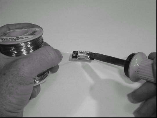
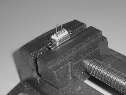
Place the connector in your vise with the solder cups facing up.
Take one of the 1" pieces of wire and heat the solder cup for Pin 4 with the soldering iron until the solder melts, then use the needle-nose pliers insert the tinned end of the wire into the cup and melt that solder, too. Remove the iron while holding the wire steady until the solder solidifies. Repeat for the other end of the wire and Pin 6.
Repeat Step 8 for the remaining 1" piece of wire and Pins 7 and 8.

Since this is just a practice connector, it won't matter which of the cable wires is connected to which pin. (When you make a real connector, you'll have to know exactly which pin carries which signal — information provided by the equipment manufacturer.) Repeat Step 8 for each of the three cable wires and Pins 2, 3, and 5.

Install the shell of the connector, being sure to capture the jacket in the cable clamping area at the back of the shell.
Tip
Sometimes you need a cable with a DB-9 or DB-25 on one end and free wire ends on the other for attachment to a terminal strip or soldering to a printed-circuit board. Save yourself a lot of work by purchasing a commercially-made cable with DB connectors attached — get a length that's twice as long as you need. Then cut it in half and use a continuity tester or multimeter to figure out which wire is connected to which pin. You're done — and you've got a spare cable to boot!