![]()
Introduction to Practical Networking
Chapter 1 begins by discussing a few of the tools that you will use throughout the book. Next, we cover the beloved OSI model and discuss how it relates to networking. We talk about all seven layers of the OSI model. Then we move on to the TCP/IP model and show its relation to the OSI model. We end the chapter discussing well-known port numbers, the different types of networks, and Cisco’s hierarchical internetwork model.
So you want to become a good network engineer? Let us give you some advice: do not believe that you know everything there is to know about networking. No matter what certifications or years of experience you have, there will always be gaps in knowledge, and people that know or have experienced issues that you may not have. Troubleshoot issues systematically from layer to layer. Use your resources—such as this book! You can never have too many resources at your disposal in your toolbox. Do not be afraid to ask for help. Do not be ashamed because you cannot resolve a problem. That is why we have teams of engineers. Everyone has their expertise and we must use each to our advantage. Remember when dealing with networks it is always better to have a second pair of eyes and another brain to help resolve issues quickly. This will help you save time and stop you from working in circles. You want to know how you can become a good network engineer? Start by reading this book and complete the lab exercises to reinforce what you have learned. The rest will come from experience on the job. Practice makes perfect!
How do you practice in a lab setting? We all cannot go around buying our own network equipment and creating our own lab environment. The best thing is to configure and test with real equipment that can be bought secondhand on eBay. There are also many tools that can be used to simulate routers in a virtual environment. Because all of the devices are virtual, they come with limitations on what you can do with them. These limitations are discussed in Appendix A.
To become proficient at anything, practice is needed, and to be efficient, tools are needed. Our tool of choice to practice and simulate network topologies is the Graphical Network Simulator (GNS3), and our tool of choice to peek into the network packets is Wireshark. There are other tools that you can use, but we found these two to be the easiest and most straightforward. Just in case you want to look at other options, a quick Internet search for “network simulators” and “network sniffers” will provide a list of the available alternatives to GNS3 and Wireshark, respectively.
GNS3 provides a simple all-in-one distribution that integrates Wireshark, VirtualBox, Qemu, and Dynamips among other tools, allowing simulation of network devices and virtualized workstations or servers. A simple visit to www.gns3.com and https://www.wireshark.org, or a search on YouTube will glean vast amounts of information on how to use the tools. You need to be able to get an IOS image; do not violate any license agreements. We will use GNS3 and Wireshark exclusively throughout this book.
Cisco Packet Tracer is a network simulation tool that allows you to simulate the configuring, operation, and troubleshooting of network devices. For more information, visit https://www.netacad.com/web/about-us/cisco-packet-tracer.
Cisco Virtual Internet Routing Lab (VIRL) is a network simulation tool that uses virtual machines running the same IOS as Cisco’s routers and switches. It allows you to configure and test real-world networks using IOS, IOS XE, IOS XR, and NX-OS. For more information, visit http://virl.cisco.com.
Open Systems Interconnection (OSI) Model
Before we define the OSI model, let’s talk about why it should be important to you. First, the OSI model is something you should understand and not just gloss over. We understand that the thought of the model can put people to sleep if you have not had that morning coffee yet, but it can be an immense aid if you know how protocols communicate with one another and how each layer operates with another. How is it that a PC can communicate using so many protocols, or why can many companies create technologies that interoperate with others’ technologies? Even though you may be a network engineer and think that you will only work at layers 2 and 3, it is important to know and understand how all the layers of OSI function. This will aid you when it comes to troubleshooting layer 1 and many of the applications you may use to monitor your devices. If you know the OSI model, you can create your own troubleshooting methodology. Gaining the theory and the hands-on practice allows you to know which layers to troubleshoot after you have tested a cable, as data gets closer to the device of the end user. Now that you know how important it is, let’s talk about the OSI model.
The OSI model is a conceptual model, also known as the seven-layer model, which was established by the International Organization for Standardization (ISO) and the International Telecommunication Union—Telecommunication Standardization Sector (ITU-T) to develop commonality in function and interface between communication protocols.
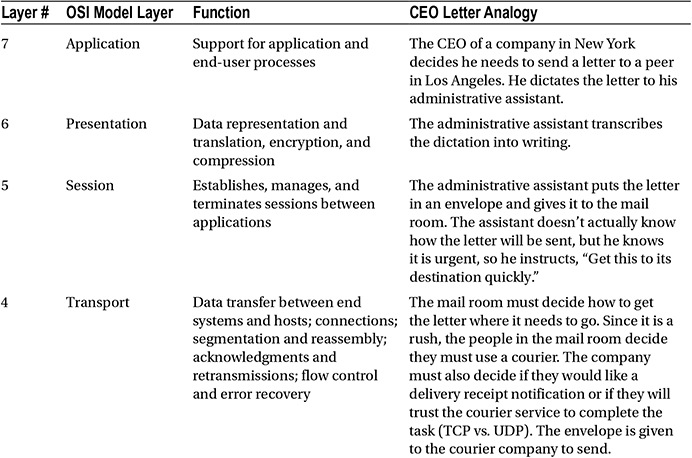
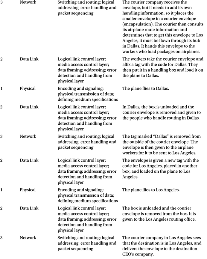
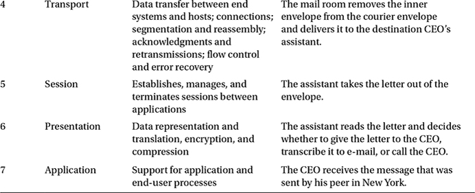
It is important to note that the OSI model is not a set rule but merely a reference guide for vendors to follow so that their products can interface with one another. The seven layers can be seen in Table 1-1. The purpose of the model is to allow multivendor networks to interoperate independently and only require knowledge of interfaces between layers.
Table 1-1. OSI Model
|
Layer Number |
Name of Layer |
|---|---|
|
7 |
Application |
|
6 |
Presentation |
|
5 |
Session |
|
4 |
Transport |
|
3 |
Network |
|
2 |
Data Link |
|
1 |
Physical |
The OSI model breaks up/groups functions of communication into seven logical layers: physical, data link, network, transport, session, presentation, and application. Each layer supports the layer above it, and is served by the level below it. It is important to note that processing is self-contained and transparent to the other layers. The application, presentation and session layers define how applications within end units communicate with one another and users. Traditional examples of end units on a network are PCs, servers, printers and scanners. However, with the evolution of the Web of Things, even your appliances and lightbulbs could be end units.
The physical, data link, network, and transport layers define how data is transmitted from source to destination. The lower layers are important in the processing of intermediary devices such as routers. Table 1-1 shows the seven layers. The layers will be discussed in more detail later in the chapter.
The following are some of the advantages of the OSI model:
- It standardizes the industry and defines what occurs at each layer of the model.
- By standardizing network components, it allows many vendors to develop products that can interoperate.
- It breaks the network communication processes into simpler and smaller components, allowing easier development, troubleshooting, and design.
- Problems in one layer will be isolated to that layer during development, in most cases.
The applications layer interfaces with users using a computer or other devices, and is also responsible for communications between users or hosts. The bottom four layers—physical, data link, network and transport—define how data is transported through the physical medium, as well as through network devices (i.e., routers). The upper three layers—session, presentation and application—know nothing about networking. Table 1-2 shows the functions of each layer in the OSI model.
Now that we know the function of each layer, we will dive into each layer individually and bring them all together after all seven layers have been discussed.
Physical Layer
The physical layer represents any medium—be it air, copper, glass, vacuum—that is used to transmit data over the given medium. The physical layer protocol must define the requirements and rules for creation, maintenance, and termination of the communications channel. In the context of the OSI model, the physical layer receives frames from the data link layer and converts them into signals; ones and zeros to be transmitted over the chosen medium. Examples of transmission mediums and the technologies used to transmit data over them are electromagnetic waves (a.k.a. wireless) for air, photonic (a.k.a. laser) for glass (a.k.a. fiber), and electrical pulses for metallic conductors, such as copper (a.k.a. Cat6 Ethernet). This layer must also specify the relationship between devices and a physical transmission medium to include layouts of pins, voltages, signal timing, frequency, number of waves, light spectrum, data rates, maximum transmission distances, link activation, and deactivation. For physical layer protocols to be useful for networking, they must be able to add context to the data being sent; this context is inserted with the use of a synchronization flag or preamble to delimit one transmission context from another. In summary, the goals of a physical layer protocol are to specify the following:
- The medium of transmission
- The physical manifestation of energy for transmission (e.g., light)
- The channel characteristics (half duplex, full duplex, serial, parallel)
- The methods for error recovery
- The timing for synchronization
- The range of transmission
- The energy levels used for transmission
Data Link Layer
The data link layer provides services to the layer above it (the network layer), and provides error handling and flow control. This layer must ensure that messages are transmitted to devices on a local area network (LAN) using physical hardware addresses. It also converts packets sent from the network layer into frames to be sent out to the physical layer to transmit. The data link layer converts packets into frames, adding a header containing the device’s physical hardware source and destination addresses, flow control and checksum data (CRC). The additional information is added to packets form a layer or capsule around the original message, and when the message is received at the distant end, this capsule is removed before the frame is sent to the network layer for processing at that layer. The data frames created by the data link layer is transmitted to the physical layer and converted into some type of signal (electrical or electromagnetic). Please note that devices at the data link layer do not care about logical addressing, only physical. Routers do not care about the actual location of your end user devices, but the data link layer does. This layer is responsible for the identification of the unique hardware address of each device on the LAN.
The data link layer is separated into two sublayers:
- Media access control (MAC) 802.3: This layer is responsible for how packets are transmitted by devices on the network. Media access is first come/first served, meaning all the bandwidth is shared by everyone. Hardware addressing is defined here, as well as the signal path, through physical topologies, including error notification, correct delivery of frames, and flow control. Every network device, computer, server, IP camera, and phone has a MAC hardware address.
- Logical link control (LLC) 802.2: This layer defines and controls error checking and packet synchronization. LLC must locate network layer protocols and encapsulate the packets. The header of the LLC lets the data link layer know how to process a packet when a frame is received.
As mentioned, the MAC layer is responsible for error notification, but this does not include error correction; this responsibility goes to the LLC. When layer 2 frames are received at the end device, the LLC recalculates the checksum to determine if the newly calculated value matches the value sent with the frame. The end device will transmit an acknowledgement signal to the transmitting end unit if the checksum values match. Else, the transmitting end device will retransmit the frame, since it is likely the frame arrived at its destination with corrupted data, or did not arrive at all.
Examples of data link layer technologies include:
- Fiber Distributed Data Interface (FDDI): A legacy technology, but it may still be used in some networks today.
- Asynchronous Transfer Mode (ATM): A legacy technology, but it may still be used in some networks today.
- Institute of Electronic and Electrical Engineers (IEEE) 802.2 (LLC)
- IEEE 802.3 (MAC)
- Frame relay: A legacy technology, but it may still be used in some networks today.
- PPP (Point-to-Point Protocol)
- High-level Data Link Control (HDLC): A legacy technology, but it may still be used in some networks today.
Network Layer
The network layer provides logical device addressing, determines the location of devices on the network, and calculates the best path to forward packets. Routers are network layer devices that provide routing within networks. This layer provides routing capabilities, creating logical paths or virtual circuits to transmit packets from source to destination. The network layer handles logical packet addressing and maps logical addresses into hardware addresses, allowing packets to reach their endpoint. This layer also chooses the route that packets take, based on factors such as link cost, bandwidth, delay, hop count, priority and traffic.
A network is a collection of many devices, each connected in some manner, which has logical addressing that allows communication throughout the network, including the devices connected to it. This communication follows the OSI model using the network, data link and physical layers. To understand how packets are processed by network layer devices, let’s look at a simplified example in Figure 1-1. The computer with IP address 192.168.1.1 sends a packet to a router interface; the destination IP address is evaluated by Router 1. Router 1 checks to determine if the destination IP is in one of its local networks. IP address 192.168.2.1 is in the router’s routing table, and is not directly connected to either of its local networks. Router 1 forwards the packet through interface FastEthernet 0/0 (F0/0), as stated in its routing table. Router 2 receives the packet and performs a lookup in its routing table to determine how to route the packet it has received. If the packet is in its routing table, it will forward the packet; else, it will drop the packet. The router sees the IP address in its local routing table and forwards the packet to its destination.
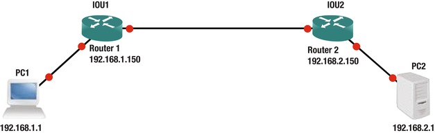
Figure 1-1. Networking example
Network layer examples include routing protocols such as Open Shortest Path First (OSPF), Routing Information Protocol (RIP), Enhanced Interior Gateway Protocol (EIGRP), Border Gateway Routing Protocol (BGP), Internet Protocol Version 4/6 (IPv4/IPv6), Internet Group Management Protocol (IGMP), and Internet Control Message Protocol (ICMP).
Transport Layer
The transport layer segments and reassembles data for the session layer. This layer provides end-to-end transport services. The network layer allows this layer to establish a logical connection between source and destination host on a network. The transport layer is responsible for establishing sessions and breaking down virtual circuits. The transport layer connections can be connectionless or connection-oriented, also known as reliable.
Flow control ensures data integrity at the transport layer by using reliable data transport. Reliable data transport uses connection-oriented sessions between end systems. The following are some of the benefits:
- Acknowledgement sent from the receiver to the sender upon receipt of the segments.
- If a segment is not acknowledged, it will be retransmitted by the sender.
- Segments are reorganized into their proper order once received at the destination.
- Congestion, overloading, and data loss is avoided through flow control.
Connection-Oriented
In reliable transport, when a device wants to transmit, it must set up connection-oriented communication by creating a session with a remote device. The session is set up by completing a three-way handshake. Once the three-way handshake is complete, the session resembles a virtual-circuit for the communication. A connection-oriented session implies that the method of communication is bidirectional, and the receiving party is expected to acknowledge the data received. The connection-oriented session analogy is akin to having a conversation (not a monologue) with someone. After the transfer is complete, the session is terminated and the virtual circuit is torn down. During the establishment of the reliable session, both hosts must negotiate and agree to certain parameters to begin transferring data. Once the connection is synchronized and established, traffic can be processed. Connection-oriented communication is needed when trying to send files via file transfer, as a connection must be made before the files can be sent. Connectionless communication is used for applications that require fast performance, such as video chatting.
Session Layer
The session layer is responsible for establishing, managing, and terminating sessions between local and remote applications. This layer controls connections between end devices and offers three modes of communication: full-duplex, half-duplex, or simplex operation. The session layer keeps applications data away from other applications data. This layer performs reassembly of data in connection-oriented mode while data is passed through, without being modified when using connectionless mode. The session layer is also responsible for the graceful close of sessions, creating checkpoints and recovery when data or connections are interrupted. This layer has the ability to resume connections or file transfers where it stopped last.
Examples of the session layer include:
- Structure Query Language (SQL): An IBM development designed to provide users with a way to define information requirements on local and remote systems.
- Remote Procedure Call (RPC): A client-server redirection tool used to disparate service environments.
- Network File System (NFS): A Sun Microsystems development that works with TCP/IP and UNIX desktops to allow access to remote resources.
Presentation Layer
The presentation layer translates data, formats code, and represents it to the application layer. This layer identifies the syntax that different applications use, and encapsulates presentation data into session protocol data units and passes this to the session layer, ensuring that data transferred from the local application layer can be read by the application layer at the remote system. The presentation layer translates data into the form that specific applications recognize and accept. If a program uses a non-ASCII code page, this layer will translate the received data into ASCII. This layer also encrypts data to be sent across the network. The presentation layer also can compress data, which increases the speed of the network. If the data is encrypted, it can only be decrypted at the application layer on the receiving system.
Examples of presentation layer standards include:
- Joint Photographic Experts Group (JPEG): Photo standards.
- Movie Picture Experts Group (MPEG) standard for compression and coding of motion video for CDs.
- Tagged Image File Format (TIFF): A high-resolution graphics format.
- Rich Text Format (RTF): A file format for exchanging text files from different word processors and operating systems.
Application Layer
The application layer interfaces between the program sending or receiving data. This layer supports end user applications. Application services are made for electronic mail (e-mail), Telnet, File Transfer Protocol (FTP) applications, and file transfers. Quality of service, user authentication, and privacy are considered at this layer due to everything being application-specific. When you send an e-mail, your e-mail program contacts the application layer.
The following are popular applications within the application layer:
- World Wide Web (WWW): Presents diverse formats—including multimedia such as graphics, text, sound, and video connecting servers—to end users.
- E-mail: Simple Mail Transfer Protocol (SMTP) and Post Office Protocol version 3 (POP3) protocols are used to allow sending and receiving, respectively, of e-mail messages between different e-mail applications.
The OSI Model: Bringing It All Together
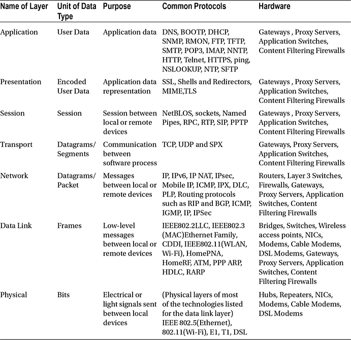
Table 1-3 shows the functions of each layer in the OSI model, including the common protocols, hardware, and data associated with each layer.
Table 1-3. The Functions of Each Layer in the OSI Model
Let’s bring the OSI model together in a way where you can see the importance of each layer. How about using Firefox to browse to a web site on a computer? You type apress.com into the web browser to contact the web server hosting the content you are requesting. This is at the application layer.
The presentation layer converts data in a way that allows images and text to be displayed, and sounds to be heard. Formats at the presentation layer include ASCII, MP3, HTML, and JPG. When you requested to be directed to the apress.com webpage, a TCP connection was created to the server using port 80. Each TCP connection is a session maintained by the session layer. The transport layer creates the TCP connections to break the webpages into datagrams that can be reassembled in the correct order and forwarded to the session layer. The network layer uses IP to locate the IP address of the web server via your default gateway. The web request is now sent to the data link layer, and it knows to use Ethernet to send the request. Finally, the transport layer uses the Ethernet for its transport protocol, and forwards the web site request to the server.
Table 1-4 shows many examples of applications and how each layer supports another.
Table 1-4. Examples of Applications and How Each Layer Helps the Applications Come Together

TCP/IP is the most used network protocol. Since you now have a firm grasp of the OSI model, we will display the correlation between the TCP/IP and OSI models. As discussed, the OSI model has seven layers, and the TCP/IP protocol has four layers. Table 1-5 shows the comparison between the OSI and TCP/IP protocol.
Table 1-5. OSI Model Comparison to TCP/IP Model with Functions of Each Layer
The application, presentation, and session layers in the OSI model correspond to the application layer in the TCP/IP model. The transport layer in the OSI model correlates to the transport layer in the TCP/IP model. The network layer in the OSI model correlates to the Internet layer in the TCP/IP model. The data link and physical layers correspond with the network interface layer in the TCP/IP model.
Similarly, when a sender transmits data via the TCP/IP protocol, applications communicate with the application layer, which sends its data to the transport layer, which sends its data to the Internet layer, which sends its data to the network interface layer to send the data over the transmission medium to the destination.
Now we will dive into the layers of the TCP/IP model.
TCP/IP Application Layer
Programs communicate to the TCP/IP application layer. Many protocols can be used at this layer, depending on the program being used. This layer also defines user interface specifications.
Several protocols are used at this layer, most notably File Transfer Protocol (FTP) for file transfers, Simple Mail Transport Protocol (SMTP) for e-mail data, and HyperText Transfer Protocol (HTTP) for web site traffic. This layer communicates with the transport layer via ports. The Internet Assigned Numbers Authority (IANA) defines which ports are to be used for which application. Standard applications always listen on port 80 for the HTTP protocol, the SMTP protocol uses port 25, and the FTP protocol uses ports 20 and 21 for sending data. The port number tells the transport protocol what type of data is inside the packet (for example, what data is being transported from a web server to a host), allowing the application protocol at the receiving side to use port 80, which will deliver the data to the web browser that requested the data.
TCP/IP Transport Layer
The TCP/IP transport layer is identical to and parallels performing the same functions as the transport layer in the OSI model. Two protocols can be used at this layer: Transmission Control Protocol (TCP) and User Datagram Protocol (UDP). The first is connection-oriented and the latter is connectionless, meaning that the TCP provides reliability and error-free delivery of data, and also maintains data integrity. TCP is used for e-mails and web site data, whereas UDP is usually used to send control data, including voice and other streaming data where speed is more important than retransmitting packets that are lost.
The transport layer receives data from the application layer and breaks it up into many packets of data. As mentioned earlier, the transport layer uses two protocols: TCP and UDP. The TCP protocol receives packets from the Internet layer, reorders the packets correctly (since packets may arrive out of order), evaluates the data in the packet, and sends an acknowledgement signal to the sender. The sender will resend the packet if no acknowledgement signal is received. Packets need to be resent if the original packet was corrupted or did not arrive at the destination. For this reason, TCP is called a reliable protocol; whereas UDP is unreliable because it does not reorder packets or send an acknowledgement signal to the sender. When UDP is used, it is the responsibility of the application to reorder packets. Both UDP and TCP receive data from the application layer and add a header to the data before sending to the Internet layer. After receiving packets from the Internet layer, the header is removed in order to forward data to the application layer and the correct port. The header contains the following information: a checksum to check whether data is intact and not corrupt; a source and destination port number; and a sequence number for reordering packets and acknowledgement. Figure 1-2 shows packets at the transport layer with header added to it.

Figure 1-2. Transport layer packet
TCP/IP Internet Layer
The TCP/IP Internet layer correlates to the network layer in the OSI model and is responsible for routing and addressing. The most common protocol used at this layer is the Internet Protocol (IP). This layer logically addresses packets with IP addresses and routes packets to different networks.
The Internet layer receives packets from the transport layer, adds source and destination IP addresses to the packet, and forwards this on to the network interface layer for transmitting to the sender. The logical (virtual addressing), also known as an IP address, allows the packet to be routed to its destination. Along the way, packets traverse many locations through routers before reaching its destination. To view an example of this, open your command prompt on your laptop or workstation. In the command prompt, enter tracert (or traceroute in Linux) apress.com. You will see the number of routers that the packet traverses to its destination.
There are many protocols in use at the Internet layer, including:
- Internet Protocol (IP): The IP receives datagrams from the transport layer and encapsulates them into packets before forwarding to the network interface layer. This protocol does not implement any acknowledgement, and so it is considered unreliable. The header in the IP datagram includes the source and destination IP addresses of the sender and the receiver.
- Internet Control Message Protocol (ICMP): The ICMP is a major protocol in the IP suite that is used by network devices to send error messages to indicate that a host or router is unreachable.
- Address Resolution Protocol (ARP): ARP is used to map IP network addresses to the hardware address that uses the data link protocol. This will be discussed further in Chapter 3.
- Reverse Address Resolution Protocol (RARP): RARP is used on workstations in a LAN to request its IP address from the ARP table.
The maximum size of the frames that are sent over a network is called the maximum transfer unit (MTU). Ethernet networks, by default, support up to 1,500 bytes, so the MTU is 1,500 bytes. The IP protocol also has a field in its header to support fragmentation. Fragmentation provides a method for networks or routers that do not support 1,500 bytes the ability to break the datagram into chunks in order to reach its destination. Once the router at the destination receives the datagram, it will reorder the fragmented frames before delivery. Figure 1-3 shows the addition of the IP header after a packet is received from the transport layer.
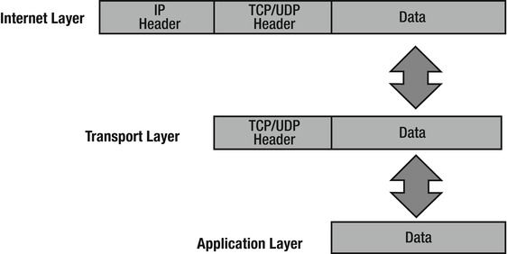
Figure 1-3. Packets at the Internet layer with header added to it
TCP/IP Network Interface Layer
The TCP/IP network interface layer relates to the data link and physical layers of the OSI model. It is responsible for using physical hardware addresses to transmit data, and defines protocols for the physical transmission of data.
Datagrams are transmitted to the network interface layer to be forwarded to its destination. This layer is defined by the type of physical connection your computer has. Most likely it will be Ethernet or wireless.
The logical link control (LLC) layer is responsible for adding the protocol used to transmit data at the Internet layer. This is necessary so the corresponding network interface layer on the receiving end knows which protocol to deliver the data to at the Internet layer. IEEE 802.2 protocol defines this layer.
Media access control (MAC) is responsible for assembling the frame that is sent over the network. It also adds the source and destination MAC addresses. This layer is defined by the IEEE 802.3 and 802.11 protocols. As shown in Figure 1-4, the LLC and MAC layers add their own headers to the datagram. The transport layer operates on datagrams or segments. When packets are received by the Internet layer, they are decapsulated into datagrams; when packets are received by the network interface layer, they are converted into Ethernet frames before being forwarded to their destination.
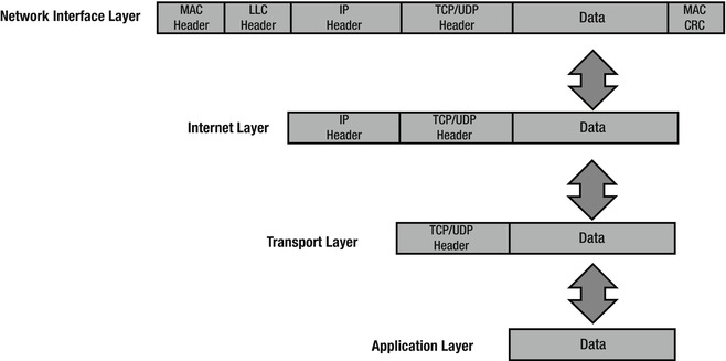
Figure 1-4. Packets at the network interface layer with headers and a trailer added to it
Reliability
How can TCP provide reliability? Through the use of acknowledgements, of course. TCP uses sequence numbers to identify the correct order of segments sent from each end device so that data can be reconstructed at the receiving end, regardless of fragmentation or packet loss. For every packet that is transmitted, the sequence number is incremented by one. The starting sequence number is randomly generated to defend against sequence prediction attacks. TCP also uses sequence numbers for error detection, allowing senders to retransmit packets that are corrupt or lost. Checksums are performed to ensure the IP header information has not been corrupted. TCP flags located in the header of TCP packets are used to control the state of a connection. Before we go through a TCP example let’s define the three TCP flags we will cover:
- Synchronize (SYN): Used to initiate and setup a session and agree on initial sequence numbers.
- Finish (FIN): Used to gracefully terminate a session. This shows that the sender has no more data to transmit.
- Acknowledgement (ACK): Used to acknowldegemt receipt of data.
Figure 1-5 displays how TCP provides reliability. The sender has sent a packet and the receiver acknowledges this packet by increasing the sequence number by one. The sender sends packet 2 and starts a timer. The packet is lost, no acknowledgement is sent back, and the timer expires. The sender resends the packet and the receiver acknowledges with an ACK.
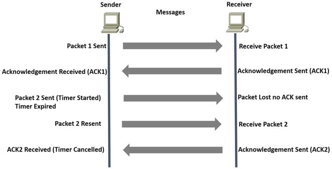
Figure 1-5. How TCP provides reliability
Three-Way Handshake and Connection Termination
When establishing a connection, TCP uses a three-way handshake. The process starts with a SYN sent by a client to a server. The server responds back with a SYN-ACK, with the acknowledgement being increased by one. Finally, the client sends an ACK back to the server to complete the connection setup.
To end a connection, a four-way handshake is completed to terminate the connection. The end that wishes to end the connection transmits a FIN packet, and the other end acknowledges with an ACK. The receiving end now sends a FIN packet with ACK. Finally, the initiating end sends an ACK to terminate the connection. Figure 1-6 shows the three- and four-way handshake processes.

Figure 1-6. The setup of the TCP three-way handshake and graceful termination of communication between peers
Let’s take a look at some actual TCP packets captured via Wireshark. Using the preceding formula, we will calculate the packet captures in Figures 1-7, 1-8, and 1-9.
Figure 1-7 shows that the SYN sequence number starts at x = 0.
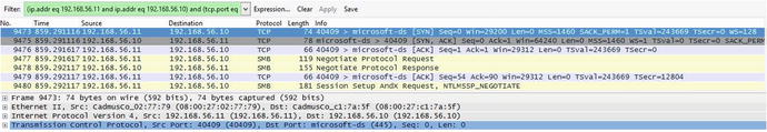
Figure 1-7. Wireshark SYN packet capture of the TCP three-way handshake
Figure 1-8 shows that the SYN sequence number starts at y = 0 and the ACK sequence number starts at x + 1, which is 1.
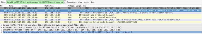
Figure 1-8. Wireshark SYN, ACK packet capture of the TCP three-way handshake
Figure 1-9 shows that the ACK sequence number is y + 1, which is 1.

Figure 1-9. Wireshark ACK packet capture of the TCP three-way handshake
User Datagram Protocol
User Datagram Protocol (UDP) is a member of the IP protocol suite. It uses a connectionless transmission model that does not complete any handshaking, thus referred to as unreliable. UDP does not provide protection for delivery, reordering, or duplicate protection. Time-sensitive and real-time applications are known to use UDP, since dropping packets is preferred to waiting for delayed or lost packets to be resent. UDP has no concept acknowledgements or datagram retransmission.
Port numbers for well-known ports range from 0 to 1023 and are used by system processes. The entire range of port numbers are from 0 to 65535. Packets received at the transport layer are forwarded to the correct application by identifying the destination port number. Table 1-6 provides the well-known port numbers for different services.
Table 1-6. Well-known Port Numbers
|
Protocol |
Port Number |
Description |
|---|---|---|
|
TCP, UDP |
20, 21 |
FTP |
|
TCP |
22 |
SSH |
|
TCP, UDP |
23 |
TELNET |
|
TCP |
25 |
SMTP |
|
TCP, UDP |
49 |
TACACS |
|
TCP, UDP |
53 |
DNS |
|
UDP |
67 |
DHCP |
|
UDP |
69 |
TFTP |
|
TCP |
80 |
HTTP |
|
TCP, UDP |
88 |
KERBEROS |
|
TCP |
110 |
POP3 |
|
TCP, UDP |
161, 162 |
SNMP |
|
TCP |
179 |
BGP |
|
TCP |
443 |
HTTPS |
|
TCP |
465 |
SMTPS |
|
TCP, UDP |
500 |
ISAKMP |
|
UDP |
514 |
SYSLOG |
|
UDP |
520 |
RIP |
|
TCP, UDP |
666 |
DOOM |
|
TCP |
843 |
ADOBE FLASH |
|
TCP |
989–990 |
FTPS |
|
TCP, UDP |
3306 |
MYSQL |
|
TCP |
3689 |
ITUNES |
|
TCP, UDP |
3724 |
WORLD OF WARCRAFT |
|
TCP |
5001 |
SLINGBOX |
|
TCP, UDP |
5060 |
SIP |
|
TCP |
6699 |
NAPSTER |
|
TCP, UDP |
6881–6999 |
BITTORRENT |
|
UDP |
14567 |
BATTLEFIED |
|
UDP |
28960 |
CALL OF DUTY |
Types of Networks
There are many different types of computer networks; most are defined by the size of the network or the type of connection. Networks can include a few network devices in a room, to millions of devices around the world. The following are networks based on size:
- Personal area network (PAN)
- Local area network (LAN)
- Campus area network (CAN)
- Metropolitan area network (MAN)
- Wide area network (WAN)
- Wireless wide area network (WWAN)
Personal Area Network
A personal area network (PAN) is a computer network organized around a single person within a single building, small office, or residence. Devices normally used in a PAN include Bluetooth headsets, computers, video game consoles, mobile phones, and peripheral devices.
Local Area Network
A local area network (LAN) normally consists of a computer network at a single location or office building. LANs can be used to share resources such as storage and printers. LANs can range from only two to thousands of computers. LANs are common in homes now thanks to the advancements in wireless communication often referred to as Wi-Fi. An example of a LAN is an office where employees access files on a shared server or can print documents to multiple shared printers. Commercial home wireless routers provide a bridge from wireless to wired to create a single broadcast domain. Even though you may have a wireless LAN, most WLANs also come with the ability to connect cables directly to the Ethernet ports on it.
Campus Area Network
A campus area network (CAN) represents several buildings/LANs within close proximity. Think of a college campus or a company’s enclosed facility, which is interconnected using routers and switches. CANs are larger than LANs, and, in fact, usually contain many LANs. CANs cover multiple buildings; however, they are smaller than MANs, as buildings in a CAN are generally on the same campus or within a really small geographical footprint (e.g., several buildings interconnected on the same street block or in a business park).
Metropolitan Area Network
A metropolitan area network (MAN) represents a computer network across an entire city, or other region. MANs are larger than CANs and can cover areas ranging from several miles to tens of miles. A MAN can be used to connect multiple CANs; for example, London and New York are cities that have MANs set up.
Wide Area Network
A wide area network (WAN) is normally the largest type of computer network. It can represent an entire country or even the entire world. WANs can be built to bring together multiple MAN or CANs. The Internet is the best example of a WAN. Corporate offices in different countries can be connected to create a WAN. WANs may use fiber optical cables or can be wireless by using microware technology or leased lines. )
Wireless Wide Area Network
A wireless wide area network (WWAN) is a WAN that uses wireless technologies for connectivity. It uses technologies such as LTE, WiMAN, UMTS, GSM, and other wireless technologies. The benefit of this type of WAN is that it allows connectivity that is not hindered by physical limitations. Most point-to-point (P2P) and point-to-multipoint (P2MP) wireless technologies are limited in distance; these networks are often referred to as wireless metropolitan area networks (WMAN). Due to the inherent nature of wireless technology, most companies use some form of encryption and authentication.
Virtual Private Network
Virtual private networks (VPNs) can be used to allow employees to remotely access their corporate network from a home office or through public Internet access, such as at a hotel, or a wireless Access Point. VPNs can also connect office locations.
Figure 1-10 shows the networks that we just discussed.
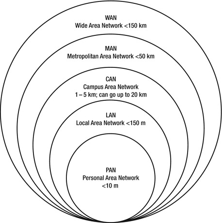
Figure 1-10. Types of networks
Hierarchical Internetwork Model
The hierarchical internetwork model was developed by Cisco; it is a three-layer model dividing networks into three layers. The layers are core, distribution, and access. Each layer is responsible for providing different services to end stations and servers.
One key component in network design is switching where you can and routing where you must, meaning that you should use switches wherever possible. Another key component is dividing network devices into zones, which separates user access networks from data centers. Separation can be achieved logically via routers and switches or firewalls. Access devices typically support end devices such as VoIP phones, printers, and computers. Networks can be divided on a per-floor basis or a per-office basis.
The core layer is the backbone of the network and normally is designed with high-end switches and high-end fiber optic cables. This layer does not route traffic to the LAN, and is only concerned with speed and reliable delivery of packets. This layer is always built with redundancy, as evident in Figure 1-11 The model begins with two core switches on the backbone, to which switching and routing is completed. Maximum performance can be achieved by using groups of links to the distribution layer and for the connection between one another.

Figure 1-11. Hierarchical model
The distribution layer connects to the access layer or edge layer. This layer is focused on switching and can be connected redundantly to both the core and user switches. Uplinks to this device should also be groups of links to achieve maximum performance. Firewalls and NAT can be configured in the layer. Routing between VLANs and workgroups are done at this layer. The devices at this layer should be able to process a large amount of traffic. In large networks, a multilayer switch should be used. Redundancy should also be considered at this layer since an outage of these devices could affect thousands of users. Devices should have redundant links to edge layer devices, and redundant power supplies should be used.
The access layer, or edge layer, includes hubs and switches, and focuses on connecting client devices to the network. This layer is responsible for clients receiving data on their computers and phones. Any device that connects users to the network is an access layer device. Figure 1-11 displays the architecture of the hierarchical internetwork model developed by Cisco.
Summary
The chapter has finally come to an end and you are on your way to becoming a network engineer. We have covered many fundamental concepts and will continue to build upon this information in the upcoming chapters. We began this chapter by discussing the OSI model and how all the layers work together, as each layer has its responsibilities and functions to perform. We discussed each layer in detail and you should have an understanding of all seven.
We also discussed TCP/IP as the most widely used protocol on the Internet today. You should understand how sessions are started and torn down to include the three-way handshake. We provided illustrations and Wireshark packet captures to allow you to actually see the packets transmitted. You should be familiar with commonly used port numbers and how they are used to transport data.
Lastly, we covered different types of networks, including LAN, CAN, MAN, WAN, and WWANs. Also, we introduced you to the hierarchical network model that is in use in most networks today. The three layers are the core, distribution, and access layers. We are now going to move forward to discuss the physical layer in the next chapter to build on the foundational information from this chapter.