![]()
Routing
Now we get to the fun, the world of routing. This chapter discusses router configurations, including static routing and dynamic routing protocols such as Routing Information Protocol (RIP), Enhanced Interior Gateway Routing Protocol (EIGRP), Open Shortest Path First (OSPF), and the Border Gateway Protocol (BGP). Routing can be compared to mail delivery. You identify the recipient of the mail by writing the name and address, and you identify yourself as the sender with your address. You put your letter in the mailbox to be picked up by the mailman. The mailman takes your letter to the post office, where it is determined how to route your letter to its destination. Your letter may pass through many post offices along the way. If there is a problem along the way, the letter is routed back to you as the sender.
Routing is the fundamental purpose of routers and all networks. If you are to be a good network engineer, you will need to have a good understanding of routing: how routing works and how to troubleshoot issues. If you work for a company, routers are very important to the overall function of the network. Most often when problems occur, the network is the first thing people question or say that there is a problem with. Understanding how routing works helps troubleshoot issues quickly and effectively. The next section gives an introduction to routing.
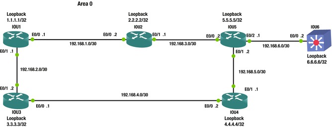
Figure 6-1 displays an example network diagram that we will use in our routing discussion.

Figure 6-1. Routing diagram
The routing table is called a RIB, or Routing Information Base. When you execute a show ip route command, the RIB is displayed. See the following output for a sample RIB. The command is run on router IOU1 in Figure 6-1.
IOU1#sh ip route
Codes: L - local, C - connected, S - static, R - RIP, M - mobile, B - BGP
       D - EIGRP, EX - EIGRP external, O - OSPF, IA - OSPF inter area
       N1 - OSPF NSSA external type 1, N2 - OSPF NSSA external type 2
       E1 - OSPF external type 1, E2 - OSPF external type 2
       i - IS-IS, su - IS-IS summary, L1 - IS-IS level-1, L2 - IS-IS level-2
       ia - IS-IS inter area, * - candidate default, U - per-user static route
       o - ODR, P - periodic downloaded static route, H - NHRP, l - LISP
       + - replicated route, % - next hop override

Gateway of last resort is not set

      192.168.1.0/24 is variably subnetted, 2 subnets, 2 masks
C        192.168.1.0/24 is directly connected, Ethernet0/0
L        192.168.1.1/32 is directly connected, Ethernet0/0
S     192.168.2.0/24 [1/0] via 192.168.1.2
                     is directly connected, Ethernet0/0
S     192.168.3.0/24 is directly connected, Ethernet0/0
S     192.168.4.0/24 is directly connected, Ethernet0/0
Let’s review the routing table. The C next to 192.168.1.0/24 lets you know that you are directly connected to this network through interface Ethernet 0/0. The L below this states that this is a local IP address on the network, and the IP address of this interface is 192.168.1.1. The S states that the router static routes to networks 192.168.2.0/24, 192.168.3.0/24, and 192.168.4.0/24 through Ethernet 0/0.
As you can see, there are two routes to network 192.168.2.0/24. One sends packets destined to this network to IP address 192.168.1.2 and the other through Ethernet 0/0. These are actually one and the same because the interface connected to Ethernet 0/0 has IP address 192.168.1.2.
The Process of Routing
If a packet arrives at IOU1 with destination address 192.168.3.4/24, what will the router do? The router looks in its routing table and forwards this packet out of interface Ethernet 0/0.
If a packet arrives at IOU1 with destination address 192.168.5.4/24, what will the router do? The router looks through its routing table but will not find a match for the destination address. The router discards the packet and sends an ICMP Destination Unreachable message out of the interface in which it received the packet addressed to IP 192.168.5.4. This can be prevented by having a default route to send packets to. We will discuss this shortly.
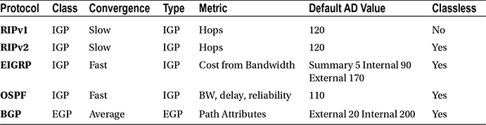
As you will see later, each routing protocol has an administrative distance (AD). Table 6-1 shows that static routes have a higher preference than other values. The AD defines how reliable a route is based on the value. The lower the value, the more reliable the route to a network is. If a route is learned via EIGRP but there is also a static route to this network, the router prefers the static route because it has the lower, more reliable AD. Table 6-1 displays default values for administrative distances.
Table 6-1. Administrative Distance Table
|
Routing Protocol |
Administrative Distance |
|---|---|
|
Connected interface |
0 |
|
Static route |
1 |
|
EIGRP summary route |
5 |
|
External BGP |
20 |
|
Internal EIGRP |
90 |
|
IGRP |
100 |
|
OSPF |
110 |
|
IS-IS |
115 |
|
RIP |
120 |
|
EGP |
140 |
|
ODR |
160 |
|
External EIGRP |
170 |
|
Internal BGP |
200 |
|
Unknown |
255 |
Any route learned from RIP has an administrative distance of 120 and EIGRP 90. When configuring static routes, you can also configure the administrative distance for the route. The router can have a static route for a network that it has also learned from RIP. In this case, the route with the lowest administrative distance is chosen. If you would like a route to be used, you can adjust the administrative distance.
Now let’s look at the ip route command:
IOU1(config)#ip route ?
  A.B.C.D  Destination prefix
  profile  Enable IP routing table profile
  static   Allow static routes
  vrf      Configure static route for a VPN Routing/Forwarding instance

IOU1(config)#ip route 192.168.2.0 ?
  A.B.C.D  Destination prefix mask

IOU1(config)#ip route 192.168.2.0 255.255.255.0 ?
  A.B.C.D            Forwarding router’s address
  Async              Async interface
  Auto-Template      Auto-Template interface
  BVI                Bridge-Group Virtual Interface
  CDMA-Ix            CDMA Ix interface
  CTunnel            CTunnel interface
  DHCP               Default Gateway obtained from DHCP
  Dialer             Dialer interface
  Ethernet           IEEE 802.3
  GMPLS              MPLS interface
  LISP               Locator/ID Separation Protocol Virtual Interface
  LongReachEthernet  Long-Reach Ethernet interface
  Loopback           Loopback interface
  MFR                Multilink Frame Relay bundle interface
  Multilink          Multilink-group interface
  Null               Null interface
  Serial             Serial
  Tunnel             Tunnel interface
  Vif                PGM Multicast Host interface
  Virtual-PPP        Virtual PPP interface
  Virtual-TokenRing  Virtual TokenRing
  vmi                Virtual Multipoint Interface
Figure 6-2 is used to discuss creating static routes.
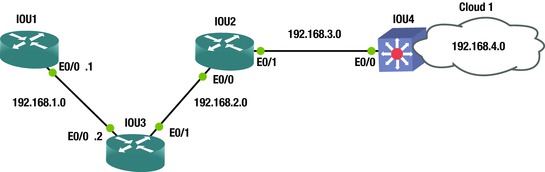
Figure 6-2. Example routing diagram
IOU1#configure terminal
Enter configuration commands, one per line. End with CNTL/Z.
IOU1(config)#ip route 192.168.2.0 255.255.255.0 Ethernet0/0
IOU1(config)#ip route 192.168.2.0 255.255.255.0 192.168.1.2
IOU1(config)#ip route 192.168.3.0 255.255.255.0 Ethernet0/0
IOU1(config)#ip route 192.168.4.0 255.255.255.0 Ethernet0/0
IOU1(config)#int e0/0
IOU1(config-if)#no shut
IOU1(config-if)#ip address 192.168.1.1 255.255.255.0
IOU1(config-if)#end
Refer to Figure 6-2 as we discuss the preceding commands. To set an IP route on a router, you simply type ip route, then the network you are routing to, followed by the subnet mask, and finally, the outgoing interface. As you can see, the connecting interface in the second ip route command is also listed. These are the two variations that can be used when using the ip route command. Network 192.168.2.0 can be reached be sending packets to the router with IP 192.168.1.2 or out interface Ethernet 0/0.
If you type the command show running-config, you can see the configuration of the device, including the IP routing commands that we just configured.
IOU1#show running-config
Building configuration...

Current configuration : 2031 bytes
!
! Last configuration change at 04:33:34 UTC Sun Jan 4 2015
version 15.2
service timestamps debug datetime msec
service timestamps log datetime msec
no service password-encryption
!
hostname IOU1
!
boot-start-marker
boot-end-marker
!
interface Ethernet0/0
 ip address 192.168.1.1 255.255.255.0

ip route 0.0.0.0 0.0.0.0 Ethernet0/0
ip route 192.168.2.0 255.255.255.0 Ethernet0/0
ip route 192.168.2.0 255.255.255.0 192.168.1.2
ip route 192.168.3.0 255.255.255.0 Ethernet0/0
ip route 192.168.4.0 255.255.255.0 Ethernet0/0
Now let’s change the administrative distance of a static route to 130 so that if we use OSPF, which has an administrative distance of 110, the route learned from OSPF is preferred. Doing this means if OSPF stopped working correctly, the router will still know how to route to this network.
IOU1(config)#ip route 192.168.2.0 255.255.255.0 192.168.1.2 ?
  <1-255>    Distance metric for this route
  multicast  multicast route
  name       Specify name of the next hop
  permanent  permanent route
  tag        Set tag for this route
  track      Install route depending on tracked item
  <cr>

IOU1(config)#ip route 192.168.2.0 255.255.255.0 192.168.1.2 130

The routing table can also be searched when looking for a specific route instead of having the router submit all routes if the routing table is large.

IOU1#show ip route 192.168.2.0
Routing entry for 192.168.2.0/24
  Known via "static", distance 130, metric 0 (connected)
  Routing Descriptor Blocks:
    192.168.1.2
      Route metric is 0, traffic share count is 1
  * directly connected, via Ethernet0/0
      Route metric is 0, traffic share count is 1
A default route is also known as the route of last resort and it is used when there is no route in the routing table that matches the destination IP address in a packet. It is typically displayed as 0.0.0.0/0 in the routing table of the router. The default route can be added by introducing the route and subnet mask with a wildcard of 0.0.0.0. A wildcard is a mask rule in which 0 means the bit must match, whereas 1 means the bit does not matter. They can be used to indicate the size of a network. For instance, a wildcard mask of 0.0.0.255 represents a /24 network. To represent a single host, you would use mask 0.0.0.0.
IOU1(config)#ip route 0.0.0.0 0.0.0.0 192.168.1.2

%Default route without gateway, if not a point-to-point interface, may impact performance
IOU1#sh ip route
Codes: L - local, C - connected, S - static, R - RIP, M - mobile, B - BGP
       D - EIGRP, EX - EIGRP external, O - OSPF, IA - OSPF inter area
       N1 - OSPF NSSA external type 1, N2 - OSPF NSSA external type 2
       E1 - OSPF external type 1, E2 - OSPF external type 2
       i - IS-IS, su - IS-IS summary, L1 - IS-IS level-1, L2 - IS-IS level-2
       ia - IS-IS inter area, * - candidate default, U - per-user static route
       o - ODR, P - periodic downloaded static route, H - NHRP, l - LISP
       + - replicated route, % - next hop override

Gateway of last resort is 192.168.1.2 to network 0.0.0.0

S*    0.0.0.0/0 [1/0] via 192.168.1.2
                is directly connected, Ethernet0/0
      192.168.1.0/24 is variably subnetted, 2 subnets, 2 masks
C        192.168.1.0/24 is directly connected, Ethernet0/0
L        192.168.1.1/32 is directly connected, Ethernet0/0
Let’s take a look at another method for configuring the gateway of last resort on the router. We can use the ip default-network command. This command has the same effect as the default route with wildcard, with the exception that it also advertises this default network when an Interior Gateway Routing Protocol (IGP) is configured. Other routers receive this default route automatically.
IOU3(config)#ip default-network 192.168.1.0
Now let’s talk about two ways to test and troubleshoot IP connectivity:
- traceroute: This is used to display the entire routing path from source to destination along a route. This provides a roundtrip time of packets received at each host along the path until the packet reaches its destination.
- ping: This is a networking utility used to test whether a host is reachable across an IP network. Ping is very useful when someone cannot reach a server or some other destination.
Figure 6-3 will be used to show how both traceroute and ping can be useful.

Figure 6-3. Routing diagram
Let’s try to ping 192.168.4.1 from IOU1:
IOU1#ping 192.168.4.1
Type escape sequence to abort.
Sending 5, 100-byte ICMP Echos to 192.168.4.1, timeout is 2 seconds:
!!!!!
Success rate is 100 percent (5/5), round-trip min/avg/max = 1/1/2 ms
You can see that the entire path is reachable and you can communicate with the switch on the far end. This is what is called “clearing the network path.”
Now let’s try a traceroute from IOU1:
IOU1#traceroute 192.168.4.1
Type escape sequence to abort.
Tracing the route to 192.168.4.1
VRF info: (vrf in name/id, vrf out name/id)
  1 192.168.1.2 5 msec 5 msec 5 msec
  2 192.168.2.2 5 msec 5 msec 5 msec
  3 192.168.3.2 6 msec 5 msec 5 msec
The traceroute displays the entire path, including the IP address of each router it crossed until it reached its destination. Imagine how useful this command can be.
Now let’s provide an example of this by removing a route to network 192.168.4.0 from router IOU2, and then try the traceroute again.
To remove the ip route from IOU2, you simply put a no in front of the ip route command.
IOU2(config)#no ip route 192.168.4.0 255.255.255.0 192.168.3.2
To verify that the route is or is not in the routing table, run the show ip route command.
We can do this two ways; the first way is shown here:
IOU2#show ip route

Gateway of last resort is not set

S     192.168.1.0/24 [1/0] via 192.168.2.1
      192.168.2.0/24 is variably subnetted, 2 subnets, 2 masks
C        192.168.2.0/24 is directly connected, Ethernet0/0
L        192.168.2.2/32 is directly connected, Ethernet0/0
      192.168.3.0/24 is variably subnetted, 2 subnets, 2 masks
C        192.168.3.0/24 is directly connected, Ethernet0/1
L        192.168.3.1/32 is directly connected, Ethernet0/1
You can see from the preceding output that network 192.168.4.0 is not in the routing table. The second way is done by adding the actual network that you are looking for to the show ip route command. If you are looking for a route to network 192.168.4.0, then you include this network in the command, as follows:
IOU2#show ip route 192.168.4.0
% Network not in table
We have verified that the route to network 192.168.4.0 has been removed; now let’s try another traceroute.
IOU1#traceroute 192.168.4.1
Type escape sequence to abort.
Tracing the route to 192.168.4.1
VRF info: (vrf in name/id, vrf out name/id)
  1 192.168.1.2 5 msec 4 msec 5 msec
  2 192.168.2.2 5 msec 5 msec 5 msec
  3 192.168.2.2 !H  !H  !H
IOU1#
As you would expect, the traceroute stops at router IOU2, which has IP address 192.168.2.2. Now you know that there is probably a routing issue on this router. After further investigation, you can now add the route to fix the network path to network 192.168.4.0.
Dynamic Routing Protocols
Static routing requires a network administrator that is responsible for updating all network changes every single time a network is added, re-routed on every device in the network that needs to reach the network. With dynamic routing protocols, as long as the neighboring routers are running the same protocol, the routers update each other’s routing tables. Imagine maintaining a network with 20+ routers and being responsible to update all routes manually. If a new network is added, a new route would need to be added to all routers. Dynamic protocols automagically update all routers in the event a link goes down and a route is no longer accessible or is to be used. In a large network, sometimes a combination of static routing and dynamic routing is used.
Dynamic routing protocols allow all routers configured to use the same protocol to learn about network failures and to receive updates for routes to destinations. Routers learn the state of networks by communicating with other neighbors by using multicast packets. If you have a larger network where every host is listening, broadcasting this way can saturate the network.
Distance-Vector Routing Protocol
Distance-vector protocols locate the best path by determining the distance through each router calculating the number of hops. RIP is a distance-vector protocol, but using hop count has several disadvantages, including the inability to choose the best route, and that it does not scale well to larger networks.
Figure 6-4 is used to calculate the hop count.

Figure 6-4. Distance-Vector diagram
Imagine you want to send a packet from IOU5 to IOU7. Because RIP uses hop count, it would choose the path through IOU6, which clearly is not the best path when you look at the bandwidth of the path through IOU8. Another reason RIP is not great is because it has a maximum hop count of 15, so a network with 20 routers would not work. RIPv2 increased its hop count to 255, but it’s still not the best protocol to use.
Link-State Routing Protocol
OSPF is an example of a link-state protocol. OSPF opts to use the links of all routers in the networks to create routing tables. OSPF calculates the cost or metric of each link by dividing 100,000,000 (100 MB) by the bandwidth of the link in bits per second. 100 MB is called the routers reference bandwidth and it is 100 by default. This means that if you have links that have a higher bandwidth than 100 MB, you will need to change the default bandwidth on all routers running OSPF. To adjust the reference bandwidth, use the auto-cost command.
IOU1(config)#router ospf 1
First, enter the OSPF configuration with the router ospf command:
IOU1(config-router)#auto-cost reference-bandwidth ?
  <1-4294967>  The reference bandwidth in terms of Mbits per second
The auto-cost command is used to change the bandwidth from a value of 1 to 4294967. 1 is the lowest cost in OSPF.
IOU1(config-router)#auto-cost reference-bandwidth 300
The bandwidth is changed to 300 MB.
Figure 6-5 is used to calculate the cost.

Figure 6-5. Link-State diagram
100 Mbps (100,000,000/100,000,000) = cost of 1 (100 Mbps = 100,000,000 bps)
Let’s go back to our example using RIP to determine the best path using OSPF.
From IOU5 to IOU7 via IOU6:
1.544 Mbps (100,000,000/1,544,000) = cost of 64 × 2 = 128
From IOU5 to IOU7 via IOU8 and IOU9:
100 Mbps (100,000,000/100,000,000) = cost of 1 × 3 = 3
This means this is the best route to IOU7. You can see the benefit of using OSPF vs. using RIP.
Hybrid Routing Protocol
Hybrid protocols use parts of both distance-vector and link-state routing protocols. EIGRP is an example of this. Cisco also defines EIGRP as an advanced distance-vector routing protocol, as opposed to a hybrid routing protocol.
RIP
As mentioned earlier, RIP (Routing Information Protocol) is a distance-vector protocol that is effective when used in small networks.
RIP version 1 uses only classful routing, so all devices in the network must be in the same subnet and use the same subnet mask. RIP version 2 sends subnet mask information with its routing table updates by using classless routing.
There are a couple of issues with RIP, such as RIP broadcasts all the routes it knows about every 30 seconds. It does this regardless of whether there has been a change in the network, which makes for slow network convergence and also causes significant overhead traffic. Another issue is that RIP does not trigger updates after a network change has occurred. If a link goes down, there is no notification until the 30 seconds have passed for that router.
Let’s configure RIP using Figure 6-6.

Figure 6-6. RIP diagram
To configure RIP, the protocol needs to be enabled by using the router rip command and configuring the networks to advertise.
IOU1(config)#router rip
IOU1(config-router)#version 2
IOU1(config-router)#network 192.168.1.0

IOU1#show ip route
Codes: L - local, C - connected, S - static, R - RIP, M - mobile, B - BGP
       D - EIGRP, EX - EIGRP external, O - OSPF, IA - OSPF inter area
       N1 - OSPF NSSA external type 1, N2 - OSPF NSSA external type 2
       E1 - OSPF external type 1, E2 - OSPF external type 2
       i - IS-IS, su - IS-IS summary, L1 - IS-IS level-1, L2 - IS-IS level-2
       ia - IS-IS inter area, * - candidate default, U - per-user static route
       o - ODR, P - periodic downloaded static route, H - NHRP, l - LISP
       + - replicated route, % - next hop override

Gateway of last resort is 192.168.1.2 to network 0.0.0.0

S*    0.0.0.0/0 [1/0] via 192.168.1.2
                is directly connected, Ethernet0/0
      192.168.1.0/24 is variably subnetted, 2 subnets, 2 masks
C        192.168.1.0/24 is directly connected, Ethernet0/0
L        192.168.1.1/32 is directly connected, Ethernet0/0
R     192.168.2.0/24 [120/1] via 192.168.1.2, 00:00:05, Ethernet0/0
R     192.168.3.0/24 [120/2] via 192.168.1.2, 00:00:05, Ethernet0/0
R     192.168.4.0/24 [120/3] via 192.168.1.2, 00:00:05, Ethernet0/0
You can see from the routing table that the router is learning routes from RIP, because next to the IP routes is an R letting you know that RIP is the source of the routes in the table. Let’s take a look at the other router configurations:
IOU3(config)#router rip
IOU3(config-router)#version 2
IOU3(config-router)#network 192.168.1.0
IOU3(config-router)#network 192.168.2.0

IOU2(config)#router rip
IOU2(config-router)#version 2
IOU2(config-router)#network 192.168.2.0
IOU2(config-router)#network 192.168.3.0

IOU4(config)#router rip
IOU4(config-router)#version 2
IOU4(config-router)#network 192.168.4.0
IOU4(config-router)#network 192.168.3.0
The passive-interface command can be used to prevent an interface from sending RIP updates, although the router continues to receive and process RIP updates on the interface.
IOU4(config)#router rip
IOU4(config-router)#passive-interface ethernet0/0
RIP version 2 supports triggered updates and allows neighbors to be configured. RIPv2 also provides support for authentication between routers.
The no auto-summary command can be used to turn off summarization to enable classless routing.
Also, the default-information originate command can be used to advertise a default route. Most routers need to have a default route to your ISP.
By using the no auto-summary command, the router propagates route 172.16.0.0/24 instead of 172.16.0.0/16.
IOU1(config)#ip route 0.0.0.0 0.0.0.0 Ethernet0/0
%Default route without gateway, if not a point-to-point interface, may impact performance
IOU1(config)#router rip
IOU1(config-router)#default-information originate
IOU1(config-router)#no auto-summary
Authentication
In order to add authentication to RIP routing you will need to include the following:
- Key chain: A key chain needs to be named; it does not need to be identical to the neighboring router.
- Key 1: The key identification number of an authentication key on a key chain; it does not need to be identical to the neighboring router.
- Key-string: The password string; it must be identical to the neighboring router.
- ip rip authentication key-chain: Enabled authentication on the interface along with which key chain to use.
- ip rip authentication mode md5: Sets the authentication mode.
Take a look at the configuration in this example:
IOU1(config)#Key chain test
IOU1(config-keychain)#Key 1
IOU1(config-keychain-key)#Key-string testRIP
IOU1(config-keychain-key)#int Ethernet0/0
IOU1(config-if)#ip rip authentication key-chain test
IOU1(config-if)#ip rip authentication mode ?
  md5   Keyed message digest
  text  Clear text authentication

IOU1(config-if)#ip rip authentication mode md5

IOU3(config)#Key chain test
IOU3(config-keychain)#Key 1
IOU3(config-keychain-key)#Key-string testRIP
IOU3(config-keychain-key)#int Ethernet0/0
IOU3(config-if)#ip rip authentication key-chain test
IOU3(config-if)#ip rip authentication mode md5
Figure 6-7 displays a RIP packet capture (PCAP).

Figure 6-7. RIP packet capture
In the RIP packet, you can see that it is a request to broadcast address 224.0.0.9 asking for a routing table. The Command field in the packet indicates that this is a response packet. A value of 2 represents a response packet. The version indicates which version of RIP you are using.
Using the debug ip rip command, you can see the effect of first placing authentication on IOU1 before placing it on IOU3 and after placing it on IOU3.
IOU1#debug ip rip
RIP protocol debugging is on
IOU1#
*Jan  4 11:29:27.031: RIP: ignored v2 packet from 192.168.1.2 !invalid authentication
IOU1#
*Jan  4 11:29:34.751: RIP: sending v2 update to 224.0.0.9 via Ethernet0/0 (192.168.1.1)
*Jan  4 11:29:34.751: RIP: build update entries
*Jan  4 11:29:34.751:   0.0.0.0/0 via 0.0.0.0, metric 1, tag 0
*Jan  4 11:29:34.751: RIP: sending v2 update to 192.168.1.2 via Ethernet0/0 (192.168.1.1)
*Jan  4 11:29:34.751: RIP: build update entries
*Jan  4 11:29:34.751:   0.0.0.0/0 via 0.0.0.0, metric 1, tag 0
*Jan  4 11:29:56.235: RIP: received packet with MD5 authentication
*Jan  4 11:29:56.235: RIP: received v2 update from 192.168.1.2 on Ethernet0/0
*Jan  4 11:29:56.235:      192.168.2.0/24 via 0.0.0.0 in 1 hops
*Jan  4 11:29:56.235:      192.168.3.0/24 via 0.0.0.0 in 2 hops
*Jan  4 11:29:56.235:      192.168.4.0/24 via 0.0.0.0 in 3 hops
You can see that a packet with invalid authentication was received before adding the configuration to IOU3. After adding the authentication commands to IOU3, a packet with MD5 authentication was received.
Another useful command is:
IOU1#sh ip rip ?
  database  IPv4 RIP database

IOU1#show ip rip database
0.0.0.0/0    auto-summary
0.0.0.0/0    redistributed
    [1] via 0.0.0.0,
192.168.1.0/24    auto-summary
192.168.1.0/24    directly connected, Ethernet0/0
192.168.2.0/24    auto-summary
192.168.2.0/24
    [1] via 192.168.1.2, 00:00:16, Ethernet0/0
192.168.3.0/24    auto-summary
192.168.3.0/24
    [2] via 192.168.1.2, 00:00:16, Ethernet0/0
The following commands are used in the next example:
Key chain test
Key 1
Key-string testRIP
int Ethernet0/0
ip rip authentication key-chain test
ip rip authentication mode text
These commands configure authentication with a password in clear text in RIP.
Figure 6-8 is an example of RIP packet captures using authentication passwords in clear text.
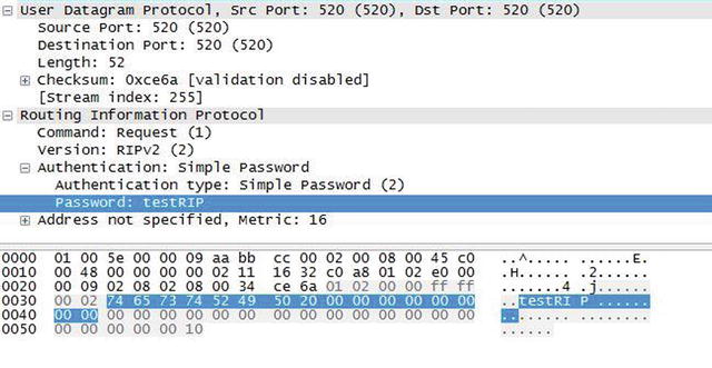
Figure 6-8. RIP authentication clear text PCAP
In the packet capture, you can see that the password is listed.
The following commands are used for the next example:
Key chain test
Key 1
Key-string testRIP
int Ethernet0/0
ip rip authentication key-chain test
ip rip authentication mode md5
The commands used above enable authentication with md5 password encryption.
Figure 6-9 is an example of RIP packet captures using authentication passwords encrypted with a MD5 hash.
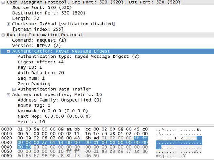
Figure 6-9. RIP authentication MD5
In the packet capture, you can see that the password is encrypted and unreadable.
EIGRP
Enhanced Interior Gateway Routing Protocol (EIGRP) is a dynamic protocol developed by Cisco that can only be used with Cisco devices. So you won’t use this protocol unless you have an all-Cisco network, because the protocol is not compatible with Juniper devices. EIGRP is based on a distance-vector algorithm, but determining the best path to a destination is better than RIP’s hop count. EIGRP uses an algorithm called DUAL, or the Diffusing Update Algorithm. EIGRP helps networks reconverge swiftly after a network change and allows load balancing across multiple paths of equal metric. EIGRP has a simple configuration and is easy to manage, which is why it is used today. EIGRP is a hybrid protocol because it also provides triggered updates, like OSPF.
Let’s configure EIGRP by using Figure 6-10.
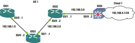
Figure 6-10. EIGRP routing diagram
To configure EIGRP, the router eigrp autonomous-system-number (AS) command must be used. An AS, or process ID number, is a number between 1 and 65535, and all routers must be configured with the same process number to exchange routing information. Multiple EIGRP process IDs can be used, but the router must be configured to redistribute routing information from one AS to another.
The no auto-summary command must be used with RIP to disable autosummarization of routes. The network command can also be typed as follows:
Network 192.168.1.0
IOU1(config)#int e0/0
IOU1(config-if)#ip address 192.168.1.1 255.255.255.0
IOU1(config-if)#router eigrp 1
IOU1(config-router)#network 192.168.1.0 0.0.0.255
IOU1(config-router)#no auto-summary
The following message notifies you that you have a neighbor and a new adjacency to this neighbor, and they should be exchanging routing information.
*Jan 4 12:17:37.180: %DUAL-5-NBRCHANGE: EIGRP-IPv4 1: Neighbor 192.168.1.2 (Ethernet0/0) is up: new adjacency
Now let’s configure the other routers based on Figure 6-10.
IOU3(config)#int e0/0
IOU3(config-if)#ip address 192.168.1.2 255.255.255.0
IOU3(config-if)#int e0/1
IOU3(config-if)#ip address 192.168.2.1 255.255.255.0
IOU3(config-if)#router eigrp 1
IOU3(config-router)#network 192.168.1.0 0.0.0.255
IOU3(config-router)#network 192.168.2.0 0.0.0.255
IOU3(config-router)#no auto-summary
IOU3(config-router)#
*Jan 4 12:17:37.186: %DUAL-5-NBRCHANGE: EIGRP-IPv4 1: Neighbor 192.168.1.1 (Ethernet0/0) is up: new adjacency
*Jan 4 12:18:34.738: %DUAL-5-NBRCHANGE: EIGRP-IPv4 1: Neighbor 192.168.2.2 (Ethernet0/1) is up: new adjacency

IOU2(config)#int e0/0
IOU2(config-if)#ip address 192.168.2.2 255.255.255.0
IOU2(config-if)#int e0/1
IOU2(config-if)#ip address 192.168.3.1 255.255.255.0
IOU2(config-if)#router eigrp 1
IOU2(config-router)#network 192.168.2.0 0.0.0.255
IOU2(config-router)#network 192.168.3.0 0.0.0.255
IOU2(config-router)#no auto-summary
*Jan  4 12:18:34.744: %DUAL-5-NBRCHANGE: EIGRP-IPv4 1: Neighbor 192.168.2.1 (Ethernet0/0) is up: new adjacency
*Jan  4 12:19:09.048: %DUAL-5-NBRCHANGE: EIGRP-IPv4 1: Neighbor 192.168.3.2 (Ethernet0/1) is up: new adjacency
IOU2(config-router)#

IOU4(config)#int e0/0
IOU4(config-if)#ip address 192.168.3.2 255.255.255.0
IOU4(config-if)#int e0/1
IOU4(config-if)#ip address 192.168.4.1 255.255.255.0
IOU4(config-if)#router eigrp 1
IOU4(config-router)#network 192.168.3.0 0.0.0.255
IOU4(config-router)#network 192.168.4.0 0.0.0.255
IOU4(config-router)#no auto-summary
*Jan  4 12:19:08.121: %DUAL-5-NBRCHANGE: EIGRP-IPv4 1: Neighbor 192.168.3.1 (Ethernet0/0) is up: new adjacency
Let’s take a look at some useful EIGRP commands:
IOU3#show ip eigrp ?
  <1-65535>   Autonomous System
  accounting  Prefix Accounting
  events      Events logged
  interfaces  interfaces
  neighbors   Neighbors
  timers      Timers
  topology    Select Topology
  traffic     Traffic Statistics
  vrf         Select a VPN Routing/Forwarding instance
Figure 6-11 displays a packet capture of an EIGRP packet.
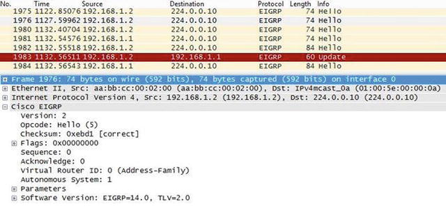
Figure 6-11. EIGRP PCAP
Reviewing the packet, you can see a hello packet sent to multicast address 224.0.0.10; the multicast address used for EIGRP. You also see the IP address of the router sending the packet. “Version:” shows the EIGRP version you are using, and “Opcode:” shows the type of packet you are sending; in this case it is a hello packet. You see the AS of the system; 1 in this case. There is also a value called TLV, or type-length-value; TLVs carry management information for EIGRP that are used to convey metric weights and hold time. The hello packet is used to identify neighbors or serve as a keepalive for neighboring devices. Figure 6-12 displays a packet capture of an EIGRP packet.

Figure 6-12. EIGRP update PCAP
The next packet is an update packet. As you can see, the update packet is not sent to a multicast address but is instead a unicast address sent directly to its neighbor. In this case, the neighbor is 192.168.1.1. The update packet contains routing information that allows the neighbor to build its topology table. Update packets have an Opcode of 1, as seen from the capture.
The show ip eigrp neighbors command displays the EIGRP active neighbors that it has exchanged data with:
IOU3#show ip eigrp neighbors
EIGRP-IPv4 Neighbors for AS(1)
H   Address          Interface     Hold Uptime     SRTT   RTO   Q     Seq
                                   (sec)           (ms)         Cnt   Num
1   192.168.2.2      Et0/1         12 00:05:26      5     100   0     6
0   192.168.1.1      Et0/0         13 00:06:23      7     100   0     5
The show ip eigrp topology command is also useful. Notice the P, which stands for passive. A router is passive when it is not performing recomputation on that route and active when it is completing recomputation on that route.
IOU3#show ip eigrp topology
EIGRP-IPv4 Topology Table for AS(1)/ID(192.168.2.1)
Codes: P - Passive, A - Active, U - Update, Q - Query, R - Reply,
       r - reply Status, s - sia Status

P 192.168.3.0/24, 1 successors, FD is 307200
        via 192.168.2.2 (307200/281600), Ethernet0/1
P 192.168.2.0/24, 1 successors, FD is 281600
        via Connected, Ethernet0/1
P 192.168.1.0/24, 1 successors, FD is 281600
        via Connected, Ethernet0/0
P 192.168.4.0/24, 1 successors, FD is 332800
        via 192.168.2.2 (332800/307200), Ethernet0/1
The show ip protocols command displays EIGRP configuration details. Two routers must have identical K values for EIGRP to establish an adjacency. The command is also helpful in determining the current K value settings before an adjacency is attempted.
IOU3#sh ip protocols
*** IP Routing is NSF aware ***

Routing Protocol is "eigrp 1"
  Outgoing update filter list for all interfaces is not set
  Incoming update filter list for all interfaces is not set
  Default networks flagged in outgoing updates
  Default networks accepted from incoming updates
  EIGRP-IPv4 Protocol for AS(1)
    Metric weight K1=1, K2=0, K3=1, K4=0, K5=0
    NSF-aware route hold timer is 240
    Router-ID: 192.168.2.1
    Topology : 0 (base)
      Active Timer: 3 min
      Distance: internal 90 external 170
      Maximum path: 4
      Maximum hopcount 100
      Maximum metric variance 1

  Automatic Summarization: disabled
  Maximum path: 4
  Routing for Networks:
    192.168.1.0
    192.168.2.0
  Routing Information Sources:
    Gateway         Distance      Last Update
    192.168.1.1           90      00:05:12
    192.168.2.2           90      00:05:12
  Distance: internal 90 external 170

IOU3#sh ip route
Codes: L - local, C - connected, S - static, R - RIP, M - mobile, B - BGP
       D - EIGRP, EX - EIGRP external, O - OSPF, IA - OSPF inter area
       N1 - OSPF NSSA external type 1, N2 - OSPF NSSA external type 2
       E1 - OSPF external type 1, E2 - OSPF external type 2
       i - IS-IS, su - IS-IS summary, L1 - IS-IS level-1, L2 - IS-IS level-2
       ia - IS-IS inter area, * - candidate default, U - per-user static route
       o - ODR, P - periodic downloaded static route, H - NHRP, l - LISP
       + - replicated route, % - next hop override

Gateway of last resort is not set

 *    192.168.1.0/24 is variably subnetted, 2 subnets, 2 masks
C*       192.168.1.0/24 is directly connected, Ethernet0/0
L        192.168.1.2/32 is directly connected, Ethernet0/0
      192.168.2.0/24 is variably subnetted, 2 subnets, 2 masks
C        192.168.2.0/24 is directly connected, Ethernet0/1
L        192.168.2.1/32 is directly connected, Ethernet0/1
D     192.168.3.0/24 [90/307200] via 192.168.2.2, 00:05:54, Ethernet0/1
D     192.168.4.0/24 [90/332800] via 192.168.2.2, 00:05: 20, Ethernet0/1
As you can see in the preceding output, the show ip route command displays routes learned from EIGRP have a D next to them.
As with RIP, in order to send or receive a default route, the default-information originate in/out command can be used to advertise or receive a default route in EIGRP.
IOU3(config-router)#default-information ?
  in   Accept input default routing information
  out  Accept output default routing information
If you do not want an interface to participate in EIGRP, the passive-interface command can be used to stop the exchange of hello packets, which will not allow for this interface to form a neighbor relationship with a remote router.
IOU3(config-router)#passive-interface Ethernet0/0
A benefit of EIGRP is the granularity with which you can configure your desired metrics. Things such as delay, bandwidth, reliability, load, and hop count can all be used to determine a best path. Each choice increases load on the CPU, but also helps with determining a true best path, which isn’t always the one with the highest bandwidth, as with OSPF.
OSPF
Open Shortest Path First, or OSPF, is one of the most widely used protocols in IP networks today. It scales well in large networks, guarantees loop-free routing, is a classless protocol, converges quickly, and is an open standard that works well on multiple vendors’ devices. OSPF’s metric is a per-link cost and does not include the entire path. OSPF does not exchange routing tables but instead sends Link-State Advertisements (LSAs), which describe the network topology that a router uses to build its Link-State database (LSDB) or its routing table. The LSDB is a topology represented in computer form. The LSDB allows each router to create a table with all the network connections between routers and their interfaces—similar to a diagram created to document a network. We will discuss areas later, but each router in the same area receives the same LSAs. Designated Routers (DRs) is the leader or master for network areas. If the DR fails then a Backup Designated Router (BDR) takes over as the DR. OSPF uses two multicast addresses: 224.0.0.5 is used to receive OSPF updates and 224.0.0.6 is used by the DR to receive updates.
An area is a network segment that is somewhat broken up into broadcast domains. OSPF can be split up into many areas, which are connected by Area Border Routers (ABRs). An ABR summarizes routing information and then sends this information to the next ABR for other areas. Each area has a 32-bit identifier number, each OSPF network should have an Area 0, and each ABR should be connected to Area 0. An Autonomous System Boundary Router (ASBR) can be used to connect OSPF routers to other protocols. The following discusses different OSPF routers:
- Backbone router: Area 0 is known as the “backbone area” or “core” of an OSPF network. All areas must have a connection to this area. A backbone router must have an interface to area 0.
- Internal router: A router is internal to an area if all of its interfaces belong to the same area.
- ABR: An ABR router must maintain separate link-state databases for each area it is connected to in memory. These routers connect multiple areas to area 0.
- ASBR: ASBR routers run more than one routing protocol and exchange information from other routing protocols into OSPF, including BGP, EIGRP, and static routes.
The two main areas are backbone and non-backbone. Area 0 is the backbone area. Figure 6-13 is a sample OSPF network diagram.

Figure 6-13. Sample OSPF area diagram
OSPF areas can differ. This section describes the many areas that we will configure, based on our network needs.
- Normal Area: A non 0 area not configured like any of the following areas.
- Stub Area: An OSPF that does not allow external LSAs.
- Totally Stubby Area: This OSPF area does not allow type 3, 4, or 5 LSAs and only receive a default summary route.
- Not so Stubby Area (NSSA): This OSPF area does not allow type 5 LSAs unless the LSAs are type 7 that have been converted to type 5 by an ABR.
- Totally Stubby Areas: This OSPF area does not allow type 3, 4, or 5 LSAs and only receive a default summary route. This OSPF area does not allow type 5 LSAs unless the LSAs are type 7 that have been converted to type 5 by an ABR. This is a combination of Totally Stubby Areas and Not so Stubby Areas.
- Transit Area: This OSPF area is used to connect two or more border routers that are used to pass OSPF traffic from one area to another.
Table 6-2 explains the different LSA types.
Table 6-2. OSPF LSA Table
|
LSA type |
Name |
Description |
|---|---|---|
|
1 |
Router LSA |
A Router-LSA includes information about a router’s interfaces within an area. These LSAs are flooded to each OSPF router in the area, but not into adjacent areas. |
|
2 |
Network LSA |
Network LSAs are flooded through the entire area, but not into adjacent areas. Originated by DRs, these LSAs describe routers connected to the network from which the LSA was received. |
|
3 |
Summary LSA |
Originated by an ABR, these LSAs advertise summary routes and interarea routes. Type 3 LSAs are used for routes to networks. |
|
4 |
Summary LSA |
Originated by ASBRs, these LSA are sent to ABRs and describe links to ASBRs. |
|
5 |
AS External LSA |
Originated by ASBRs to describe routes to networks that are external to the AS. Type 5 LSAs are flooded through the entire AS. |
|
7 |
NSSA External LSA |
Originated by NSSA ASBRs; similar to Type 5 LSAs except that they are only flooded throughout the NSSA area. Although Type 5 LSA are not allowed in NSSA areas, Type 7 LSAs are converted into Type 5 LSAs by an ABR when received from an ASBR, which sends this to the entire AS. |
Figures 6-14 and 6-15 are OSPF packet captures.

Figure 6-14. OSPF PCAP
The OSPF packet seen in Figure 6-14 is a hello packet. We can see the packet is sent to multicast destination address 224.0.0.5. The OSPF header contains the version of OSPF which is 2 in our packet and the message Type which is a Hello Packet in this example. The Auth Type represents the authentication type used, in our case it is 0 representing no authentication is being used. We see the hello interval of 10 seconds and the dead interval of 40 seconds. The router priority can be seen and is 1 which is used to determine the DR and BDR. We can also see that the area ID is 0 so we know we are in the backbone area. Hello packets are used to discover neighbors and exchange parameters such as dead interval and hold time; these must match to build neighbor adjacencies. These packets are also used as keepalive mechanisms and if no hello is received within the set dead interval the router will consider the neighbor down.
Figure 6-15 displays an OSPF LSA update packet. We can see that the LSA Update packet is sent directly to its neighbors’ address of 192.168.1.1. We can see the message type is LS Update or 4. We can see networks being advertised in this LSA is a type stub with network ID 192.168.1.0 and it is a stub network. LSAs contain routing metric and topology information for the OSPF network, which is sent to neighboring routers.
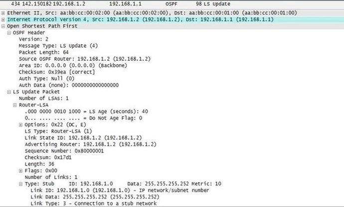
Figure 6-15. OSPF LSA update PCAP
Using Figure 6-16 as an example we will configure OSPF.
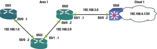
Figure 6-16. OSPF routing diagram
Configuring OSPF
To enable OSPF, use the router ospf command. OSPF will be configured using Figure 6-16.
IOU1(config)#int e0/0
IOU1(config-if)#ip address 192.168.1.1 255.255.255.0
IOU1(config)#router ospf ?
  <1-65535>  Process ID

IOU1(config)#router ospf 1
IOU1(config-router)#network 192.168.1.0 ?
  A.B.C.D  OSPF wild card bits
The wildcard mask is used to represent the interfaces and networks that will participate and be advertised in OSPF.
Let’s take a look at calculating the wildcard mask. An easy way to calculate the wildcard mask is to subtract 255.255.255.255 from the subnet mask.
- Take network 192.168.1.0 with a subnet mask of 255.255.255.0.
- The wildcard mask will then be 0.0.0.255.
Let’s look at our example again 255.255.255.0 – 255.255.255.255 = 0.0.0.255
IOU1(config-router)#network 192.168.1.0 0.0.0.255 area ?
  <0-4294967295>  OSPF area ID as a decimal value
  A.B.C.D         OSPF area ID in IP address format

IOU1(config-router)#network 192.168.1.0 0.0.0.255 area 1
IOU1(config-router)#log-adjacency-changes
IOU1(config-router)#passive-interface default
IOU1(config-router)#no passive-interface Ethernet0/0
IOU1(config-router)#default-information originate
*Jan  4 21:04:34.446: %OSPF-5-ADJCHG: Process 1, Nbr 192.168.2.1 on Ethernet0/0 from LOADING to FULL, Loading Done
OSPF can also be enabled on the interface in lieu of the router ospf command.
IOU2(config)#int e0/0
IOU2(config-if)#ip address 192.168.1.1 255.255.255.0
IOU2(config-if)#ip ospf ?
  <1-65535>            Process ID

       IOU2(config-if)#ip ospf 1 ?
  area  Set the OSPF area ID

IOU2(config-if)#ip ospf 1 area ?
  <0-4294967295>  OSPF area ID as a decimal value
  A.B.C.D         OSPF area ID in IP address format
IOU2(config-if)#ip ospf 1 area 0
You see in the preceding output that the neighbors have created an adjacency as the status went from loading to full. Let’s take a look at the ospf processes in more detail using Table 6-3.
Table 6-3. OSPF State Table
|
OSPF State | |
|---|---|
|
Down |
The initial state before any information is exchanged and no active neighbor detected |
|
Init |
Hello packet is received but two-way conversation has not been received |
|
Two-way |
Bidirectional traffic has been established |
|
ExStart |
Master/slave roles determined; the first step to creating adjacency |
|
Exchange |
The link-state database (LSDB) is sent and OSPF protocol packets are exchanged |
|
Loading |
Exchange of LSAs, to populate LSDBs |
|
Full |
Neighbors are fully adjacent and the LSDBs are fully synchronized |
The passive-interface default command sets all interfaces to not participate in ospf. You can use the no passive-interface command followed by the interface to determine which interfaces will participate in ospf.
The default-information originate command is used to inject a default route into ospf. Let’s look at router IOU3 to see if the default route is on the router.
IOU3#show ip route
*Jan  4 22:02:45.742: %SYS-5-CONFIG_I: Configured from console by console
IOU3#sh ip route
Codes: L - local, C - connected, S - static, R - RIP, M - mobile, B - BGP
       D - EIGRP, EX - EIGRP external, O - OSPF, IA - OSPF inter area
       N1 - OSPF NSSA external type 1, N2 - OSPF NSSA external type 2
       E1 - OSPF external type 1, E2 - OSPF external type 2
       i - IS-IS, su - IS-IS summary, L1 - IS-IS level-1, L2 - IS-IS level-2
       ia - IS-IS inter area, * - candidate default, U - per-user static route
       o - ODR, P - periodic downloaded static route, H - NHRP, l - LISP
       + - replicated route, % - next hop override

Gateway of last resort is not set

O*E2  0.0.0.0/0 [110/1] via 192.168.1.1, 00:53:16, Ethernet0/0
 *    192.168.1.0/24 is variably subnetted, 2 subnets, 2 masks
The default route is identified in the routing table on IOU3, identified as a type 2 external route.
IOU3(config)#int e0/0
IOU3(config-if)#ip address 192.168.1.2 255.255.255.0
IOU3(config-if)#int e0/1
IOU3(config-if)#ip address 192.168.2.1 255.255.255.0
IOU3(config)#router ospf 1
IOU3(config-router)#network 192.168.1.0 0.0.0.255 area 1
IOU3(config-router)#network 192.168.2.0 0.0.0.255 area 1
IOU3(config-router)#log-adjacency-changes
IOU3(config-router)#passive-interface default
IOU3(config-router)#no passive-interface Ethernet0/0
IOU3(config-router)#no passive-interface Ethernet0/1
*Jan  4 21:04:34.448: %OSPF-5-ADJCHG: Process 1, Nbr 192.168.1.1 on Ethernet0/0 from LOADING to FULL, Loading Done
IOU3(config-router)#no passive-interface Ethernet0/1
*Jan  4 21:05:39.508: %OSPF-5-ADJCHG: Process 1, Nbr 192.168.3.1 on Ethernet0/1 from LOADING to FULL, Loading Done

IOU2(config)#int e0/0
IOU2(config-if)#ip address 192.168.2.2 255.255.255.0
IOU2(config-if)#int e0/1
IOU2(config-if)#ip address 192.168.3.1 255.255.255.0
IOU2(config)#router ospf 1
IOU2(config-router)#network 192.168.2.0 0.0.0.255 area 1
IOU2(config-router)#network 192.168.3.0 0.0.0.255 area 1
IOU2(config-router)#log-adjacency-changes
IOU2(config-router)#passive-interface default
IOU2(config-router)#no passive-interface Ethernet0/0
IOU2(config-router)#no passive-interface Ethernet0/1
*Jan  4 21:05:39.510: %OSPF-5-ADJCHG: Process 1, Nbr 192.168.2.1 on Ethernet0/0 from LOADING to FULL, Loading Done
*Jan  4 21:06:17.650: %OSPF-5-ADJCHG: Process 1, Nbr 192.168.4.1 on Ethernet0/1 from LOADING to FULL, Loading Done

IOU4(config)#int e0/0
IOU4(config-if)#ip address 192.168.3.2 255.255.255.0
IOU4(config-if)#int e0/1
IOU4(config-if)#ip address 192.168.4.1 255.255.255.0
IOU4(config)#router ospf 1
IOU4(config-router)#network 192.168.3.0 0.0.0.255 area 1
IOU4(config-router)#network 192.168.4.0 0.0.0.255 area 1
IOU4(config-router)#log-adjacency-changes
IOU4(config-router)#passive-interface default
IOU4(config-router)#no passive-interface Ethernet0/0
IOU4(config-router)#no passive-interface Ethernet0/1
*Jan  4 21:05:36.707: %OSPF-5-ADJCHG: Process 1, Nbr 192.168.3.1 on Ethernet0/0 from 2WAY to DOWN, Neighbor Down: Interface down or detached
IOU4(config-router)#no passive-interface Ethernet0/1
*Jan  4 21:06:16.719: %OSPF-5-ADJCHG: Process 1, Nbr 192.168.3.1 on Ethernet0/0 from LOADING to FULL, Loading Done

IOU1#show ip route
Codes: L - local, C - connected, S - static, R - RIP, M - mobile, B - BGP
       D - EIGRP, EX - EIGRP external, O - OSPF, IA - OSPF inter area
       N1 - OSPF NSSA external type 1, N2 - OSPF NSSA external type 2
       E1 - OSPF external type 1, E2 - OSPF external type 2
       i - IS-IS, su - IS-IS summary, L1 - IS-IS level-1, L2 - IS-IS level-2
       ia - IS-IS inter area, * - candidate default, U - per-user static route
       o - ODR, P - periodic downloaded static route, H - NHRP, l - LISP
       + - replicated route, % - next hop override

Gateway of last resort is 192.168.1.2 to network 0.0.0.0

S*    0.0.0.0/0 [1/0] via 192.168.1.2
                is directly connected, Ethernet0/0
      192.168.1.0/24 is variably subnetted, 2 subnets, 2 masks
C        192.168.1.0/24 is directly connected, Ethernet0/0
L        192.168.1.1/32 is directly connected, Ethernet0/0
O     192.168.2.0/24 [110/20] via 192.168.1.2, 00:02:41, Ethernet0/0
O     192.168.3.0/24 [110/30] via 192.168.1.2, 00:02:03, Ethernet0/0
O     192.168.4.0/24 [110/40] via 192.168.1.2, 00:01:53, Ethernet0/0

All network routes learned from ospf are represented with an O next to it.
The show ip ospf database command can be used if you want to view your ospf routing database, also known as the Link-State Database (LSDB).
IOU1#sh ip ospf database

            OSPF Router with ID (192.168.1.1) (Process ID 1)

                Router Link States (Area 1)

Link ID         ADV Router      Age         Seq#       Checksum Link count
192.168.1.1     192.168.1.1     238         0x80000002 0x0095E5 1
192.168.2.1     192.168.2.1     174         0x80000002 0x003A4B 2
192.168.3.1     192.168.3.1     137         0x80000003 0x0080FC 2
192.168.4.1     192.168.4.1     137         0x80000003 0x003BAB 2

                Net Link States (Area 1)

Link ID         ADV Router      Age         Seq#       Checksum
192.168.1.1     192.168.1.1     238         0x80000001 0x00B5D5
192.168.2.2     192.168.3.1     175         0x80000001 0x00A4E0
192.168.3.2     192.168.4.1     138         0x80000001 0x00A8D8
IOU1#sh ip protocols
*** IP Routing is NSF aware ***

Routing Protocol is "ospf 1"
  Outgoing update filter list for all interfaces is not set
  Incoming update filter list for all interfaces is not set
  Router ID 192.168.1.1
  Number of areas in this router is 1. 1 normal 0 stub 0 nssa
  Maximum path: 4
  Routing for Networks:
    192.168.1.0 0.0.0.255 area 1
  Passive Interface(s):
    Ethernet0/1
    Ethernet0/2
    Ethernet0/3
(output omitted)

  Routing Information Sources:
    Gateway         Distance      Last Update
    192.168.3.1          110      00:02:48
    192.168.2.1          110      00:04:02
    192.168.4.1          110      00:02:10
  Distance: (default is 110)

To display your neighbor use the show ip ospf neighbor
IOU1#show ip ospf neighbor

Neighbor ID     Pri   State           Dead Time   Address         Interface
192.168.2.1       1   FULL/BDR        00:00:36    192.168.1.2     Ethernet0/0
The show ip ospf event command can be used to troubleshoot OSPF if your neighbors are not coming up or routes are missing.
IOU1#show ip ospf event

            OSPF Router with ID (192.168.1.1) (Process ID 1)

20   *Jan  4 21:09:26.242: Schedule SPF, Topo Base, Area 1, spf-type Full, Change in LSA Type RLSID 192.168.1.1, Adv-Rtr 192.168.1.1

(output omitted)

62   *Jan  4 21:06:18.188: Rcv New Type-2 LSA, LSID 192.168.3.2, Adv-Rtr 192.168.4.1, Seq# 80000001, Age 3, Area 1
63   *Jan  4 21:06:18.188: Schedule SPF, Topo Base, Area 1, spf-type Full, Change in LSA Type NLSID 192.168.3.2, Adv-Rtr 192.168.4.1
64   *Jan  4 21:06:18.188: DB add:  192.168.3.2  0xAD86EC 178
66   *Jan  4 21:06:18.155: Schedule SPF, Topo Base, Area 1, spf-type Full, Change in LSA Type RLSID 192.168.3.1, Adv-Rtr 192.168.3.1
67   *Jan  4 21:06:17.650: Rcv New Type-1 LSA, LSID 192.168.4.1, Adv-Rtr 192.168.4.1, Seq# 80000002, Age 37, Area 1
68   *Jan  4 21:06:17.650: Schedule SPF, Topo Base, Area 1, spf-type Full, Change in LSA Type RLSID 192.168.4.1, Adv-Rtr 192.168.4.1
69   *Jan  4 21:06:17.650: DB add:  192.168.4.1  0xAD882C 179
107  *Jan  4 21:05:40.044: Rcv New Type-2 LSA, LSID 192.168.2.2, Adv-Rtr 192.168.3.1, Seq# 80000001, Age 2, Area 1
108  *Jan  4 21:05:40.044: Schedule SPF, Topo Base, Area 1, spf-type Full, Change in LSA Type NLSID 192.168.2.2, Adv-Rtr 192.168.3.1
138  *Jan  4 21:04:34.943: Schedule SPF, Topo Base, Area 1, spf-type Full, Change in LSA Type RLSID 192.168.2.1, Adv-Rtr 192.168.2.1
139  *Jan  4 21:04:34.943: DB add:  192.168.2.1  0xAD8BEC 179
140  *Jan  4 21:04:34.943: Schedule SPF, Topo Base, Area 1, spf-type Full, Change in LSA Type RLSID 192.168.1.1, Adv-Rtr 192.168.1.1
141  *Jan  4 21:04:34.941: Generate Changed Type-1 LSA, LSID 192.168.1.1, Seq# 80000002, Age 0, Area 1
142  *Jan  4 21:04:34.446: Neighbor 192.168.2.1, Interface Ethernet0/0 state changes from LOADING to FULL
143  *Jan  4 21:04:34.446: Neighbor 192.168.2.1, Interface Ethernet0/0 state changes from EXCHANGE to LOADING
144  *Jan  4 21:04:34.441: Interface Ethernet0/0 state changes from DR to DR
145  *Jan  4 21:04:34.441: Elect DR:  Ethernet0/0  192.168.1.1
146  *Jan  4 21:04:34.441: Elect BDR:  Ethernet0/0  192.168.2.1
By default, OSPF chooses the highest IP address on an active interface on the router to determine its router ID. The router ID identifies each OSPF router in the network and must be unique. If a loopback address is on the router, it is always preferred because this interface never goes down and is a virtual address. Alternatively, you can also set the router ID statically using the router-id command.
You can use the show ip ospf command to view the current router ID.
IOU1(config)#do show ip ospf
 Routing Process "ospf 1" with ID 192.168.1.1
(output omitted)
IOU1(config)#router ospf 1
IOU1(config-router)#router-id 1.1.1.1
% OSPF: Reload or use "clear ip ospf process" command, for this to take effect
IOU1(config-router)#interface loopback 1
IOU1(config-if)#ip address 1.1.1.1 255.255.255.255
IOU1#clear ip ospf process
Reset ALL OSPF processes? [no]: yes
*Jan  4 22:45:04.723: %OSPF-5-ADJCHG: Process 1, Nbr 192.168.2.1 on Ethernet0/0 from FULL to DOWN, Neighbor Down: Interface down or detached
*Jan  4 22:45:04.733: %OSPF-5-ADJCHG: Process 1, Nbr 192.168.2.1 on Ethernet0/0 from LOADING to FULL, Loading Done
IOU1#sh ip ospf
 Routing Process "ospf 1" with ID 1.1.1.1
The clear ip ospf process command was used to restart the OSPF process and so the router could change its router ID to 1.1.1.1.
BGP
Border Gateway Protocol (BGP) is an external gateway protocol, whereas the others reviewed thus far are internal gateway protocols. BGP is the backbone protocol used on the Internet; it is responsible for routing between ISP networks. BGP networks are called prefixes and they must be advertised in an autonomous system. To learn routes, an autonomous system advertises its route to other autonomous systems. BGP is a path-vector routing protocol that uses a 12-step process to determine best paths. The discussion of path selection is rather large; there are other books totally dedicated to BGP that cover this process, as it is out of the scope of this book. As the AS advertises the routes, it prepends its own Autonomous System Number (ASN) to the path. An ASN is globally unique and used to eliminate loops. Again, there are entire books dedicated to BGP, so this book will only cover some of the real-world BGP scenarios and not all of its features.
If BGP routers are communicating with routers in the same AS, they use the Internal Border Gateway Protocol (iBGP); and when routers communicate with routers in different ASs, they use External Border Gateway Protocol (eBGP). Figure 6-17 shows our BGP configuration.

Figure 6-17. BGP routing diagram
BGP Configuration
This section configures BGP routing based on the example shown in Figure 6-17.
IOU1(config)#int e0/0
IOU1(config-if)#ip address 192.168.1.1 255.255.255.0
IOU1(config)#int loopback 1
IOU1(config-if)#ip address 1.1.1.1 255.255.255.255
The router bgp command allows you to enter into BGP coniguration mode.
IOU1(config-if)#router bgp 1
The network command is used to state which interface on your router will participate in BGP. If you review Figure 6-18, you can see that Ethernet0/0 will participate in BGP given that it is a part of network 192.168.1.0.
IOU1(config-router)#network 192.168.1.0 mask 255.255.255.0
The neighbor statement is the neighbor’s IP address and AS. Unlike OSPF and EIGRP, you must manually configure each neighbor’s IP address followed by their AS.
IOU1(config-router)#neighbor 192.168.1.2 remote-as 1
IOU1(config-router)#no synchronization
Synchronization is enabled by default; it is used when your AS is a pass-through from one AS to another and some routers in your AS do not run BGP.
IOU1(config)#ip route 192.168.1.0 255.255.255.0 null0
A route needs to be added to the network address stated in the preceding statement so that the prefix is announced. If it is pointed to the null0 interface, BGP will always advertise the prefix.
IOU3(config)#int e0/0
IOU3(config-if)#ip address 192.168.1.2 255.255.255.0
IOU3(config-if)#int e0/1
IOU3(config-if)#ip address 192.168.2.1 255.255.255.0
IOU3(config)#int loopback 1
IOU3(config-if)#ip address 2.2.2.2 255.255.255.255
IOU3(config-if)#router bgp 1
IOU3(config-router)#network 192.168.1.0 mask 255.255.255.0
IOU3(config-router)#network 192.168.2.0 mask 255.255.255.0
IOU3(config-router)#neighbor 192.168.1.1 remote-as 1
IOU3(config-router)#neighbor 192.168.2.2 remote-as 1
IOU3(config)#ip route 192.168.1.0 255.255.255.0 null0
IOU3(config)#ip route 192.168.2.0 255.255.255.0 null0

IOU2(config)#int e0/0
IOU2(config-if)#ip address 192.168.2.2 255.255.255.0
IOU2(config-if)#int e0/1
IOU2(config-if)#ip address 192.168.3.1 255.255.255.0
IOU2(config)#int loopback 1
IOU2(config-if)#ip address 3.3.3.3 255.255.255.255
IOU2(config-if)#router bgp 1
IOU2(config-router)#network 192.168.2.0 mask 255.255.255.0
IOU2(config-router)#network 192.168.3.0 mask 255.255.255.0
IOU2(config-router)#neighbor 192.168.2.1 remote-as 1
IOU2(config-router)#neighbor 192.168.3.2 remote-as 1
IOU2(config)#ip route 192.168.2.0 255.255.255.0 null0
IOU2(config)#ip route 192.168.3.0 255.255.255.0 null0

IOU4(config)#int e0/0
IOU4(config-if)#ip address 192.168.3.2 255.255.255.0
IOU4(config-if)#int e0/1
IOU4(config-if)#ip address 192.168.4.1 255.255.255.0
IOU4(config)#int loopback 1
IOU4(config-if)#ip address 4.4.4.4 255.255.255.255
IOU4(config-if)#router bgp 1
IOU4(config-router)#network 192.168.3.0
IOU4(config-router)#network 192.168.4.0
IOU4(config-router)#neighbor 192.168.3.1 remote-as 1
IOU4(config-router)#no synchronization
IOU4(config)#ip route 192.168.3.0 255.255.255.0 null0
IOU4(config)#ip route 192.168.4.0 255.255.255.0 null0
The show ip bgp neighbor command can be used to view information related to BGP neighbors.
IOU1#show ip bgp neighbor
BGP neighbor is 192.168.1.2,  remote AS 1, internal link
  BGP version 4, remote router ID 2.2.2.2
  BGP state = Established, up for 00:01:53
  Last read 00:00:02, last write 00:00:05, hold time is 180, keepalive interval is 60 seconds
  (Output Omitted)
Connection state is ESTAB, I/O status: 1, unread input bytes: 0
Connection is ECN Disabled, Mininum incoming TTL 0, Outgoing TTL 255
Local host: 192.168.1.1, Local port: 15366
Foreign host: 192.168.1.2, Foreign port: 179
We can see that the neighbor adjacency is established or complete and the designated port for BGP is 179. The show ip bgp command displays information related to BGP on the router.
IOU3#show ip bgp
BGP table version is 3, local router ID is 2.2.2.2
Status codes: s suppressed, d damped, h history, * valid, > best, i - internal,
              r RIB-failure, S Stale, m multipath, b backup-path, f RT-Filter,
              x best-external, a additional-path, c RIB-compressed,
Origin codes: i - IGP, e - EGP, ? - incomplete
RPKI validation codes: V valid, I invalid, N Not found

     Network          Next Hop            Metric LocPrf Weight Path
 *>  192.168.1.0      0.0.0.0                  0         32768 i
 *>  192.168.2.0      0.0.0.0                  0         32768 i
The do can be placed in front of Cisco commands that you would enter in privileged mode while in configuration mode.
IOU3(config)#do sh ip route
Codes: L - local, C - connected, S - static, R - RIP, M - mobile, B - BGP
       D - EIGRP, EX - EIGRP external, O - OSPF, IA - OSPF inter area
       N1 - OSPF NSSA external type 1, N2 - OSPF NSSA external type 2
       E1 - OSPF external type 1, E2 - OSPF external type 2
       i - IS-IS, su - IS-IS summary, L1 - IS-IS level-1, L2 - IS-IS level-2
       ia - IS-IS inter area, * - candidate default, U - per-user static route
       o - ODR, P - periodic downloaded static route, H - NHRP, l - LISP
       + - replicated route, % - next hop override

Gateway of last resort is not set

      1.0.0.0/32 is subnetted, 1 subnets
S        1.1.1.1 is directly connected, Ethernet0/0
      2.0.0.0/32 is subnetted, 1 subnets
C        2.2.2.2 is directly connected, Loopback1
 *    192.168.1.0/24 is variably subnetted, 2 subnets, 2 masks
C*       192.168.1.0/24 is directly connected, Ethernet0/0
L        192.168.1.2/32 is directly connected, Ethernet0/0
      192.168.2.0/24 is variably subnetted, 2 subnets, 2 masks
C        192.168.2.0/24 is directly connected, Ethernet0/1
L        192.168.2.1/32 is directly connected, Ethernet0/1
B     192.168.3.0/24 [200/0] via 192.168.2.2, 00:08:48

IOU3#sh ip bgp summary
BGP router identifier 2.2.2.2, local AS number 1
BGP table version is 3, main routing table version 3
2 network entries using 296 bytes of memory
2 path entries using 128 bytes of memory
1/1 BGP path/bestpath attribute entries using 136 bytes of memory
0 BGP route-map cache entries using 0 bytes of memory
0 BGP filter-list cache entries using 0 bytes of memory
BGP using 560 total bytes of memory
BGP activity 2/0 prefixes, 2/0 paths, scan interval 60 secs

Neighbor        V   AS MsgRcvd MsgSent   TblVer  InQ OutQ Up/Down  State/PfxRcd
192.168.1.1     4    1       0       0        1    0    0 never    Idle
192.168.2.2     4    1       0       0        1    0    0 never    Active
Viewing the output from the show ip bgp summary provides you with information such as router-id and AS. Also you can see the state of two connections: Idle and Active. Both mean the adjacency with the neighbor is not up, else it would say established, as shown earlier.
IOU1#show ip bgp neighbors
BGP neighbor is 192.168.1.2,  remote AS 1, internal link
  BGP version 4, remote router ID 0.0.0.0
  BGP state = Active
Using Table 6-4, let’s walk through the BGP states and what is happening at each state.
Table 6-4. BGP State Table
|
BGP State | |
|---|---|
|
IDLE |
In this state, the route to the neighbor is verified and no incoming connections are allowed |
|
Connect |
In this state, BGP awaits for a TCP connection to complete; failure could result to Active, Connect or IDLE state |
|
Active |
In this state, BGP attempts to establish a BGP peer relationship with the neighbor; failure could result in Active of Idle state |
|
OpenSent |
In this state, an OPEN message is sent to the neighbor and awaits an OPEN reply; failure could result in Active of Idle state |
|
OpenConfirm |
In this state, the neighbor has replied with the OPEN message and keepalives can be sent; if no keepalives are received the state moves back to Idle |
|
Established |
In this state, the connection is complete and BGP can exchange information with neighbors |
Figure 6-18 will be used to display the update-source command.
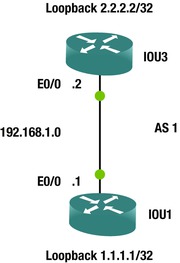
Figure 6-18. BGP routing diagram
The router-id command updates the loopback address to be the router ID for BGP; so if the physical link goes down, and multiple links are used, the adjacency does not tear down. The update-source command can be used also.
IOU1(config)#int e0/0
IOU1(config-if)#ip address 192.168.1.1 255.255.255.0
IOU1(config)#int loopback 1
IOU1(config-if)#ip address 1.1.1.1 255.255.255.255
IOU1(config)#router bgp 1
IOU1(config-router)#neighbor 2.2.2.2 remote-as 1
IOU1(config-router)#neighbor 2.2.2.2 update-source Loopback 1
The update-source command specifies the neighbor IP address of 2.2.2.2 and tells the router to use Loopback 1 for our source address.
IOU1(config-router)#no synchronization
IOU1(config)#ip route 2.2.2.2 255.255.255.255 Ethernet0/0
*Jan  5 04:36:10.562: %BGP-5-ADJCHANGE: neighbor 2.2.2.2 Up

IOU3(config)#int e0/0
IOU3(config-if)#ip address 192.168.1.2 255.255.255.0
IOU3(config)#int loopback 1
IOU3(config-if)#ip address 2.2.2.2 255.255.255.255
IOU3(config)#router bgp 1
IOU3(config-router)#neighbor 1.1.1.1 remote-as 1
IOU3(config-router)#neighbor 1.1.1.1 update-source Loopback1
IOU3(config-router)#no synchronization
IOU3(config)#ip route 1.1.1.1 255.255.255.255 Ethernet0/0
*Jan  5 04:36:10.561: %BGP-5-ADJCHANGE: neighbor 1.1.1.1 Up
Notice the output from the show ip bgp neighbors command, where the remote router ID and the state of the adjacency are highlighted.
IOU1#show ip bgp neighbors
BGP neighbor is 2.2.2.2, remote AS 1, internal link
  BGP version 4, remote router ID 2.2.2.2
  BGP state = Established, up for 00:17:57
Figure 6-19 is a BGP packet capture.
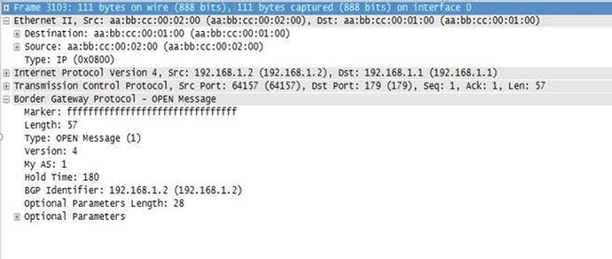
Figure 6-19. BGP PCAP
The packet capture shown in Figure 6-19 is a BGP OPEN Message. This message is sent after the TCP three-way handshake has been completed and is used to begin a BGP peering session. This message contains information about the BGP neighbor that has initiated the session and options supported, such as the BGP version number. In the message, you can see the Type of message shown as OPEN Message and the AS is 1. It displays the BGP Identifier, which is the sending device. Also note that the Destination Port used 179, which is only used by BGP.
Administrative Distance
We talked about the administrative distance of each routing protocol. You can alternatively use the distance command for each routing protocol to change the default administrative distances for each. The AD involves changing the way that the router chooses its best paths if multiple routing protocols are used or if dynamic protocols are used in conjunction with static or default routes. It must be done with great care, and only with proper planning and understanding of the possible consequences of changing the default administrative distances. Next we will change the administrative distances for RIP, EIGRP, OSPF and BGP.
You can specify the distance for networks in RIP by using the distance command.
IOU1(config)#router rip
IOU1(config-router)#network 192.168.1.0
IOU1(config-router)#distance ?
  <1-255>  Administrative distance

IOU1(config-router)#distance 15 ?
  A.B.C.D  IP Source address
  <cr>

IOU1(config-router)#distance 15 192.168.1.0 ?
  A.B.C.D  Wildcard bits
IOU1(config-router)#distance 15 192.168.1.2 0.0.0.0
IOU1(config-router)#distance 200 192.168.1.0 0.0.0.255
IOU1(config-router)#distance 255
You can specify the distance for routes learned from both internal and external neighbors:
IOU1(config-router)#router eigrp 1
IOU1(config-router)#network 192.168.1.0
IOU1(config-router)#distance ?
  <1-255>  Set route administrative distance
  eigrp    Set distance for internal and external routes

IOU1(config-router)#distance eigrp ?
  <1-255>  Distance for internal routes

IOU1(config-router)#distance eigrp 55 ?
  <1-255>  Distance for external routes
IOU1(config-router)#distance eigrp 55 200
You can also control the distance, depending on whether the neighboring router is in the same area:
IOU1(config-router)#router ospf 1

IOU1(config-router)#distance ?
  <1-255>  Administrative distance
  ospf     OSPF distance

IOU1(config-router)#distance ospf ?
  external    External type 5 and type 7 routes
  inter-area  Inter-area routes
  intra-area  Intra-area routes

IOU1(config-router)#distance ospf inter-area ?
  <1-255>  Distance for inter-area routes
IOU1(config-router)#distance ospf inter-area 115
IOU1(config-router)#distance ospf intra-area 105
IOU1(config-router)#distance ospf external 125
You can configure BGP distances for internal, external, and local routes:
IOU1(config-router)#router bgp 1
IOU1(config-router)#distance ?
  <1-255>  Administrative distance
  bgp      BGP distance
  mbgp     MBGP distance

IOU1(config-router)#distance bgp ?
  <1-255>  Distance for routes external to the AS

IOU1(config-router)#distance bgp 115 ?
  <1-255>  Distance for routes internal to the AS

IOU1(config-router)#distance bgp 115 220 ?
  <1-255>  Distance for local routes
IOU1(config-router)#distance bgp 115 220 50
Exercises
This section introduces exercises to reinforce what was learned in this chapter.
EXERCISE 1 / STATIC ROUTING
Configure all interfaces and IP addresses, and add all static routes from IOU1 to IOU4 using the following diagram. Configure a default route on IOU4. Test pinging from IOU1 to IOU2; IOU1 to IOU3; and IOU1 to IOU4. Use the following figure to complete the exercise.
EXERCISE 2 / RIP
Configure all interfaces and IP addresses, and enable RIP on all routers according to the following diagram. Test pinging from IOU1 to IOU2; IOU1 to IOU3; IOU1 to IOU4; IOU1 to IOU5; and IOU1 to IOU6. Check to make sure that RIP is advertising routes. Use the following figure to complete the exercise.

EXERCISE 3 / EIGRP
Configure all interfaces and IP addresses, and enable EIGRP on all routers according to the following diagram. Test pinging from IOU1 to IOU2; IOU1 to IOU3; IOU1 to IOU4; and IOU1 TO IOU5. Check to make sure that EIGRP is advertising routes and verify neighbor relationship. Use the following figure to complete the exercise.

EXERCISE 4 / OSPF
Configure all interfaces and IP addresses, and enable OSPF on all routers according to the following diagram. Make sure that the router ID is the loopback address on each router. By default, all devices should not participate in OSPF. Test pinging from IOU1 to IOU2; IOU1 to IOU3; IOU1 to IOU4; IOU1 to IOU5; and IOU1 to IOU6. Check to make sure that OSPF is advertising routes by displaying the LSDB and your neighbors. Use OSPF Process number 1 and Area 0. Use the following figure to complete the exercise.
EXERCISE 5 / BGP
Configure all interfaces and IP addresses, and enable BGP on all routers according to the following diagram. Use the loopback addresses to establish the neighbor relationship. Make sure that the router ID is the loopback address on each router. Test pinging from IOU1 to IOU2. Verify the neighbor adjacency. Check that the adjacency does not drop when interface on IOU1 is shut. Use the following figure to complete the exercise.

Exercise Answers
This section provides answers to the exercise questions.
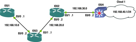
Exercise 1
Configure all interfaces and IP addresses, and add all static routes from IOU1 to IOU4 using the following diagram. Configure a default route on IOU4. Test pinging from IOU1 to IOU2; IOU1 to IOU3; and IOU1 to IOU4. Use Figure 6-20 and the following answers with commands to review the exercise.

Figure 6-20. Static routing answer diagram
IOU1(config)#int ethernet0/0
IOU1(config-if)#ip address 192.168.10.1 255.255.255.0
IOU1(config-if)#no shut
IOU1(config-if)#ip route 192.168.20.0 255.255.255.0 192.168.10.2
IOU1(config)#ip route 192.168.30.0 255.255.255.0 192.168.10.2
IOU1(config)#ip route 192.168.40.0 255.255.255.0 192.168.10.2

IOU3(config)#int ethernet0/0
IOU3(config-if)#ip address 192.168.10.2 255.255.255.0
IOU3(config-if)#no shut
IOU3(config-if)#int ethernet0/1
IOU3(config-if)#ip address 192.168.20.1 255.255.255.0
IOU3(config-if)#no shut
IOU3(config-if)#ip route 192.168.30.0 255.255.255.0 192.168.20.2
IOU3(config)#ip route 192.168.40.0 255.255.255.0 192.168.20.2

IOU2(config)#int e0/0
IOU2(config-if)#ip address 192.168.20.2 255.255.255.0
IOU2(config-if)#int e0/1
IOU2(config-if)#no shut
IOU2(config-if)#ip address 192.168.30.1 255.255.255.0
IOU2(config-if)#no shut
IOU2(config-if)#ip route 192.168.40.0 255.255.255.0 192.168.30.2
IOU2(config)#ip route 192.168.10.0 255.255.255.0 192.168.20.1

IOU4(config)#int e0/0
IOU4(config-if)#ip address 192.168.30.2 255.255.255.0
IOU4(config-if)#no shut
IOU4(config-if)#int e0/1
IOU4(config-if)#ip address 192.168.40.1 255.255.255.0
IOU4(config-if)#no shut
IOU4(config-if)#ip route 0.0.0.0 0.0.0.0 192.168.30.1

IOU1#sh ip route
Codes: L - local, C - connected, S - static, R - RIP, M - mobile, B - BGP
       D - EIGRP, EX - EIGRP external, O - OSPF, IA - OSPF inter area
       N1 - OSPF NSSA external type 1, N2 - OSPF NSSA external type 2
       E1 - OSPF external type 1, E2 - OSPF external type 2
       i - IS-IS, su - IS-IS summary, L1 - IS-IS level-1, L2 - IS-IS level-2
       ia - IS-IS inter area, * - candidate default, U - per-user static route
       o - ODR, P - periodic downloaded static route, H - NHRP, l - LISP
       + - replicated route, % - next hop override

Gateway of last resort is 0.0.0.0 to network 0.0.0.0

S        192.168.10.0/24 is variably subnetted, 2 subnets, 2 masks
C        192.168.10.0/24 is directly connected, Ethernet0/0
L        192.168.10.1/32 is directly connected, Ethernet0/0
S     192.168.20.0/24 [1/0] via 192.168.10.2
S     192.168.30.0/24 [1/0] via 192.168.10.2
S     192.168.40.0/24 [1/0] via 192.168.10.2

IOU1#ping 192.168.10.2
Type escape sequence to abort.
Sending 5, 100-byte ICMP Echos to 192.168.10.2, timeout is 2 seconds:
.!!!!
Success rate is 80 percent (4/5), round-trip min/avg/max = 6/6/7 ms
IOU1#ping 192.168.20.2
Type escape sequence to abort.
Sending 5, 100-byte ICMP Echos to 192.168.20.2, timeout is 2 seconds:
!!!!!
Success rate is 100 percent (5/5), round-trip min/avg/max = 5/5/5 ms
IOU1#ping 192.168.30.2
Type escape sequence to abort.
Sending 5, 100-byte ICMP Echos to 192.168.30.2, timeout is 2 seconds:
!!!!!
Success rate is 100 percent (5/5), round-trip min/avg/max = 5/5/6 ms
IOU1#ping 192.168.40.1
Type escape sequence to abort.
Sending 5, 100-byte ICMP Echos to 192.168.40.1, timeout is 2 seconds:
!!!!!
Success rate is 100 percent (5/5), round-trip min/avg/max = 5/7/11 ms

IOU1#traceroute 192.168.40.1
Type escape sequence to abort.
Tracing the route to 192.168.40.1
VRF info: (vrf in name/id, vrf out name/id)
  1 192.168.10.2 5 msec 5 msec 5 msec
  2 192.168.20.2 6 msec 6 msec 6 msec
  3 192.168.30.2 7 msec 5 msec 6 msec
Exercise 2
Configure all interfaces and IP addresses and enable RIP on all routers according to the following diagram. Test pinging from IOU1 to IOU2; IOU1 to IOU3; IOU1 to IOU4; IOU1 to IOU5; IOU1 to IOU6. Check to make sure RIP is advertising routes. Use Figure 6-21 and the following answers with commands to review the exercise.

Figure 6-21. RIP routing answer diagram
IOU1(config)#int e0/0
IOU1(config-if)#ip address 192.168.1.1 255.255.255.252
IOU1(config-if)#no shut
IOU1(config-if)#int e0/1
IOU1(config-if)#ip address 192.168.2.1 255.255.255.252
IOU1(config-if)#no shut
IOU1(config-if)#router rip
IOU1(config-router)#network 192.168.1.0
IOU1(config-router)#network 192.168.2.0

IOU2(config-if)#int e0/0
IOU2(config-if)#ip address 192.168.1.2 255.255.255.252
IOU2(config-if)#no shut
IOU2(config-if)#int e0/1
IOU2(config-if)#ip address 192.168.3.1 255.255.255.252
IOU2(config-if)#no shut
IOU2(config-if)#router rip
IOU2(config-router)#network 192.168.3.0
IOU2(config-router)#network 192.168.1.0

IOU3(config)#int e0/0
IOU3(config-if)#ip address 192.168.2.2 255.255.255.252
IOU3(config-if)#no shut
IOU3(config-if)#int e0/1
IOU3(config-if)#ip address 192.168.4.1 255.255.255.252
IOU3(config-if)#no shut
IOU3(config-if)#router rip
IOU3(config-router)#network 192.168.2.0
IOU3(config-router)#network 192.168.4.0

IOU4(config)#int e0/0
IOU4(config-if)#ip address 192.168.4.2 255.255.255.252
IOU4(config-if)#no shut
IOU4(config-if)#int e0/1
IOU4(config-if)#ip address 192.168.5.1 255.255.255.252
IOU4(config-if)#no shut
IOU4(config-if)#router rip
IOU4(config-router)#network 192.168.4.0
IOU4(config-router)#network 192.168.5.0

IOU5(config)#int e0/0
IOU5(config-if)#ip address 192.168.3.2 255.255.255.252
IOU5(config-if)#no shut
IOU5(config-if)#int e0/1
IOU5(config-if)#ip address 192.168.5.2 255.255.255.252
IOU5(config-if)#no shut
IOU5(config-if)#int e0/2
IOU5(config-if)#ip address 192.168.6.1 255.255.255.252
IOU5(config-if)#router rip
IOU5(config-router)#network 192.168.3.0
IOU5(config-router)#network 192.168.5.0
IOU5(config-router)#network 192.168.6.0

IOU6(config)#int e0/0
IOU6(config-if)#no switchport
IOU6(config-if)#ip address 192.168.6.2 255.255.255.252
IOU6(config-if)#no shut
IOU6(config-if)#router rip
IOU6(config-router)#network 192.168.6.0

IOU1#sh ip route rip
Codes: L - local, C - connected, S - static, R - RIP, M - mobile, B - BGP
       D - EIGRP, EX - EIGRP external, O - OSPF, IA - OSPF inter area
       N1 - OSPF NSSA external type 1, N2 - OSPF NSSA external type 2
       E1 - OSPF external type 1, E2 - OSPF external type 2
       i - IS-IS, su - IS-IS summary, L1 - IS-IS level-1, L2 - IS-IS level-2
       ia - IS-IS inter area, * - candidate default, U - per-user static route
       o - ODR, P - periodic downloaded static route, H - NHRP, l - LISP
       + - replicated route, % - next hop override

Gateway of last resort is not set

R     192.168.3.0/24 [120/1] via 192.168.1.2, 00:00:02, Ethernet0/0
R     192.168.4.0/24 [120/1] via 192.168.2.2, 00:00:08, Ethernet0/1
R     192.168.5.0/24 [120/2] via 192.168.2.2, 00:00:08, Ethernet0/1
                     [120/2] via 192.168.1.2, 00:00:02, Ethernet0/0
R     192.168.6.0/24 [120/2] via 192.168.1.2, 00:00:02, Ethernet0/0

We can see that all of our networks are being advertised through RIP.

IOU1#ping 192.168.1.2
Type escape sequence to abort.
Sending 5, 100-byte ICMP Echos to 192.168.1.2, timeout is 2 seconds:
!!!!!
Success rate is 100 percent (5/5), round-trip min/avg/max = 2/4/5 ms
IOU1#ping 192.168.2.2
Type escape sequence to abort.
Sending 5, 100-byte ICMP Echos to 192.168.2.2, timeout is 2 seconds:
!!!!!
Success rate is 100 percent (5/5), round-trip min/avg/max = 5/5/7 ms
IOU1#ping 192.168.3.2
Type escape sequence to abort.
Sending 5, 100-byte ICMP Echos to 192.168.3.2, timeout is 2 seconds:
!!!!!
Success rate is 100 percent (5/5), round-trip min/avg/max = 2/5/7 ms
IOU1#ping 192.168.4.2
Type escape sequence to abort.
Sending 5, 100-byte ICMP Echos to 192.168.4.2, timeout is 2 seconds:
!!!!!
Success rate is 100 percent (5/5), round-trip min/avg/max = 4/5/6 ms
IOU1#ping 192.168.5.2
Type escape sequence to abort.
Sending 5, 100-byte ICMP Echos to 192.168.5.2, timeout is 2 seconds:
!!!!!
Success rate is 100 percent (5/5), round-trip min/avg/max = 5/5/7 ms
IOU1#ping 192.168.6.2
Type escape sequence to abort.
Sending 5, 100-byte ICMP Echos to 192.168.6.2, timeout is 2 seconds:
!!!!!
Success rate is 100 percent (5/5), round-trip min/avg/max = 6/6/6 ms
Exercise 3
Configure all interfaces and IP addresses, and enable EIGRP on all routers according to the following diagram. Test pinging from IOU1 to IOU2; IOU1 to IOU3; IOU1 to IOU4; and IOU1 TO IOU5. Check to make sure that EIGRP is advertising routes and verify neighbor relationship. Use Figure 6-22 to complete the exercise.

Figure 6-22. EIGRP routing answer diagram
IOU1(config)#int e0/0
IOU1(config-if)#ip address 192.168.1.1 255.255.255.252
IOU1(config-if)#int e0/1
IOU1(config-if)#ip address 192.168.2.1 255.255.255.252
IOU1(config-if)#router eigrp 200
IOU1(config-router)#network 192.168.1.0 0.0.0.3
IOU1(config-router)#network 192.168.2.0 0.0.0.3

IOU3(config)#int e0/0
IOU3(config-if)#ip address 192.168.2.2 255.255.255.252
IOU3(config-if)#int e0/1
IOU3(config-if)#ip address 192.168.4.1 255.255.255.252
IOU3(config-if)#router eigrp 200
IOU3(config-router)#network 192.168.2.0 0.0.0.3
IOU3(config-router)#network 192.168.4.0 0.0.0.3

IOU2(config)#int e0/0
IOU2(config-if)#ip address 192.168.1.2 255.255.255.252
IOU2(config-if)#int e0/1
IOU2(config-if)#ip address 192.168.3.1 255.255.255.252
IOU2(config-if)#router eigrp 200
IOU2(config-router)#network 192.168.1.0 0.0.0.3
IOU2(config-router)#network 192.168.3.0 0.0.0.3

IOU5(config)#int e0/0
IOU5(config-if)#ip address 192.168.3.2 255.255.255.252
IOU5(config-if)#int e0/1
IOU5(config-if)#ip address 192.168.5.2 255.255.255.252
IOU5(config-if)#router eigrp 200
IOU5(config-router)#network 192.168.3.0 0.0.0.3
IOU5(config-router)#network 192.168.5.0 0.0.0.3

IOU4(config)#int e0/0
IOU4(config-if)#ip address 192.168.4.2 255.255.255.252
IOU4(config-if)#int e0/1
IOU4(config-if)#ip address 192.168.5.1 255.255.255.252
IOU4(config)#router eigrp 200
IOU4(config-router)#network 192.168.4.0 0.0.0.3
IOU4(config-router)#network 192.168.5.0 0.0.0.3

IOU1#sh ip route eigrp
Codes: L - local, C - connected, S - static, R - RIP, M - mobile, B - BGP
       D - EIGRP, EX - EIGRP external, O - OSPF, IA - OSPF inter area
       N1 - OSPF NSSA external type 1, N2 - OSPF NSSA external type 2
       E1 - OSPF external type 1, E2 - OSPF external type 2
       i - IS-IS, su - IS-IS summary, L1 - IS-IS level-1, L2 - IS-IS level-2
       ia - IS-IS inter area, * - candidate default, U - per-user static route
       o - ODR, P - periodic downloaded static route, H - NHRP, l - LISP
       + - replicated route, % - next hop override

Gateway of last resort is not set

      192.168.3.0/30 is subnetted, 1 subnets
D        192.168.3.0 [90/307200] via 192.168.1.2, 00:04:05, Ethernet0/0
      192.168.4.0/30 is subnetted, 1 subnets
D        192.168.4.0 [90/307200] via 192.168.2.2, 00:05:49, Ethernet0/1
      192.168.5.0/30 is subnetted, 1 subnets
D        192.168.5.0 [90/332800] via 192.168.2.2, 00:00:38, Ethernet0/1
                     [90/332800] via 192.168.1.2, 00:00:38, Ethernet0/0

IOU1#sh ip eigrp topology
EIGRP-IPv4 Topology Table for AS(200)/ID(192.168.2.1)
Codes: P - Passive, A - Active, U - Update, Q - Query, R - Reply,
       r - reply Status, s - sia Status

P 192.168.3.0/30, 1 successors, FD is 307200
        via 192.168.1.2 (307200/281600), Ethernet0/0
P 192.168.2.0/30, 1 successors, FD is 281600
        via Connected, Ethernet0/1
P 192.168.1.0/30, 1 successors, FD is 281600
        via Connected, Ethernet0/0
P 192.168.4.0/30, 1 successors, FD is 307200
        via 192.168.2.2 (307200/281600), Ethernet0/1
P 192.168.5.0/30, 2 successors, FD is 332800
        via 192.168.1.2 (332800/307200), Ethernet0/0
        via 192.168.2.2 (332800/307200), Ethernet0/1

IOU1#ping 192.168.1.2
Type escape sequence to abort.
Sending 5, 100-byte ICMP Echos to 192.168.1.2, timeout is 2 seconds:
!!!!!
Success rate is 100 percent (5/5), round-trip min/avg/max = 3/5/7 ms
IOU1#ping 192.168.2.2
Type escape sequence to abort.
Sending 5, 100-byte ICMP Echos to 192.168.2.2, timeout is 2 seconds:
!!!!!
Success rate is 100 percent (5/5), round-trip min/avg/max = 5/6/8 ms
IOU1#ping 192.168.3.2
Type escape sequence to abort.
Sending 5, 100-byte ICMP Echos to 192.168.3.2, timeout is 2 seconds:
!!!!!
Success rate is 100 percent (5/5), round-trip min/avg/max = 5/5/6 ms
IOU1#ping 192.168.4.2
Type escape sequence to abort.
Sending 5, 100-byte ICMP Echos to 192.168.4.2, timeout is 2 seconds:
!!!!!
Success rate is 100 percent (5/5), round-trip min/avg/max = 5/6/7 ms
IOU1#ping 192.168.5.2
Type escape sequence to abort.
Sending 5, 100-byte ICMP Echos to 192.168.5.2, timeout is 2 seconds:
!!!!!
Success rate is 100 percent (5/5), round-trip min/avg/max = 5/7/12 ms
Exercise 4
Configure all interfaces and IP addresses, and enable OSPF on all routers according to the following diagram. Make sure that the router ID is the loopback address on each router. By default, all devices should not participate in OSPF. Test pinging from IOU1 to IOU2; IOU1 to IOU3; IOU1 to IOU4; IOU1 to IOU5; and IOU1 to IOU6. Check to make sure that OSPF is advertising routes by displaying the LSDB and your neighbors. Use Figure 6-23 and the following answers with commands to review the exercise.
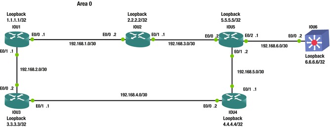
Figure 6-23. OSPF routing answer diagram
IOU1(config)#int e0/0
IOU1(config-if)#ip address 192.168.1.1 255.255.255.252
IOU1(config-if)#int e0/1
IOU1(config-if)#ip address 192.168.2.1 255.255.255.252
IOU1(config)#int loopback1
IOU1(config-if)#ip address 1.1.1.1 255.255.255.255
IOU1(config-if)#router ospf 1
IOU1(config-router)#passive-interface default
IOU1(config-router)#network 192.168.1.0 0.0.0.3 area 0
IOU1(config-router)#network 192.168.2.0 0.0.0.3 area 0
IOU1(config-router)#network 1.1.1.1 0.0.0.0 area 0
IOU1(config-router)#no passive-interface e0/0
IOU1(config-router)#no passive-interface e0/1
IOU1(config-router)#router-id 1.1.1.1
IOU1(config-router)#do clear ip ospf process

IOU3(config)#int e0/0
IOU3(config-if)#ip address 192.168.2.2 255.255.255.252
IOU3(config-if)#int e0/1
IOU3(config-if)#ip address 192.168.4.1 255.255.255.252
IOU3(config)#int loopback1
IOU3(config-if)#ip address 3.3.3.3 255.255.255.255
IOU3(config-if)#router ospf 1
IOU3(config-router)#passive-interface default
IOU3(config-router)#network 192.168.2.0 0.0.0.3 area 0
IOU3(config-router)#network 192.168.4.0 0.0.0.3 area 0
IOU3(config-router)#network 3.3.3.3 0.0.0.0 area 0
IOU3(config-router)#no passive-interface e0/0
IOU3(config-router)#no passive-interface e0/1
IOU3(config-router)#router-id 3.3.3.3
IOU3(config-router)#do clear ip ospf process

IOU2(config)#int e0/0
IOU2(config-if)#ip address 192.168.1.2 255.255.255.252
IOU2(config-if)#int e0/1
IOU2(config-if)#ip address 192.168.3.1 255.255.255.252
IOU2(config)#int loopback1
IOU2(config-if)#ip address 2.2.2.2 255.255.255.255
IOU2(config-if)#router ospf 1
IOU2(config-router)#passive-interface default
IOU2(config-router)#network 192.168.1.0 0.0.0.3 area 0
IOU2(config-router)#network 192.168.3.0 0.0.0.3 area 0
IOU2(config-router)#network 2.2.2.2 0.0.0.0 area 0
IOU2(config-router)#no passive-interface e0/0
IOU2(config-router)#no passive-interface e0/1
IOU2(config-router)#router-id 2.2.2.2

IOU5(config)#int e0/0
IOU5(config-if)#ip address 192.168.3.2 255.255.255.252
IOU5(config-if)#int e0/1
IOU5(config-if)#ip address 192.168.5.2 255.255.255.252
IOU5(config)#int e0/2
IOU5(config-if)#ip address 192.168.6.1 255.255.255.252
IOU5(config-if)#int loopback1
IOU5(config-if)#ip address 5.5.5.5 255.255.255.255
IOU5(config-if)#router ospf 1
IOU5(config-router)#passive-interface default
IOU5(config-router)#no passive-interface e0/0
IOU5(config-router)#no passive-interface e0/1
IOU5(config-router)#no passive-interface e0/2
IOU5(config-router)#network 192.168.3.0 0.0.0.3 area 0
IOU5(config-router)#network 192.168.5.0 0.0.0.3 area 0
IOU5(config-router)#network 192.168.6.0 0.0.0.3 area 0
IOU5(config-router)#network 5.5.5.5 0.0.0.0 area 0
IOU5(config-router)#router-id 5.5.5.5

IOU4(config)#int e0/0
IOU4(config-if)#ip address 192.168.4.2 255.255.255.252
IOU4(config-if)#int e0/1
IOU4(config-if)#ip address 192.168.5.1 255.255.255.252
IOU4(config)#int loopback1
IOU4(config-if)#ip address 4.4.4.4 255.255.255.255
IOU4(config-if)#router ospf 1
IOU4(config-router)#passive-interface default
IOU4(config-router)#no passive-interface e0/0
IOU4(config-router)#no passive-interface e0/1
IOU4(config-router)#router-id 4.4.4.4
IOU4(config-router)#network 192.168.4.0 0.0.0.3 area 0
IOU4(config-router)#network 192.168.5.0 0.0.0.3 area 0
IOU4(config-router)#network 4.4.4.4 0.0.0.0 area 0

IOU6(config-if)#int e0/0
IOU6(config-if)#no switchport
IOU6(config-if)#ip address 192.168.6.2 255.255.255.252
IOU6(config-if)#int loopback1
IOU6(config-if)#ip address 6.6.6.6 255.255.255.255
IOU6(config-if)#router ospf 1
IOU6(config-router)#passive-interface default
IOU6(config-router)#router-id 6.6.6.6
IOU6(config-router)#no passive-interface e0/0
IOU6(config-router)#network 192.168.6.0 0.0.0.3 area 0
IOU6(config-router)#network 6.6.6.6 0.0.0.0 area 0

IOU1#sh ip route ospf
Codes: L - local, C - connected, S - static, R - RIP, M - mobile, B - BGP
       D - EIGRP, EX - EIGRP external, O - OSPF, IA - OSPF inter area
       N1 - OSPF NSSA external type 1, N2 - OSPF NSSA external type 2
       E1 - OSPF external type 1, E2 - OSPF external type 2
       i - IS-IS, su - IS-IS summary, L1 - IS-IS level-1, L2 - IS-IS level-2
       ia - IS-IS inter area, * - candidate default, U - per-user static route
       o - ODR, P - periodic downloaded static route, H - NHRP, l - LISP
       + - replicated route, % - next hop override

Gateway of last resort is not set

      2.0.0.0/32 is subnetted, 1 subnets
O        2.2.2.2 [110/11] via 192.168.1.2, 00:05:30, Ethernet0/0
      3.0.0.0/32 is subnetted, 1 subnets
O        3.3.3.3 [110/11] via 192.168.2.2, 00:05:30, Ethernet0/1
      4.0.0.0/32 is subnetted, 1 subnets
O        4.4.4.4 [110/21] via 192.168.2.2, 00:05:30, Ethernet0/1
      5.0.0.0/32 is subnetted, 1 subnets
O        5.5.5.5 [110/21] via 192.168.1.2, 00:05:30, Ethernet0/0
      6.0.0.0/32 is subnetted, 1 subnets
O        6.6.6.6 [110/31] via 192.168.1.2, 00:05:30, Ethernet0/0
      192.168.3.0/30 is subnetted, 1 subnets
O        192.168.3.0 [110/20] via 192.168.1.2, 00:05:30, Ethernet0/0
      192.168.4.0/30 is subnetted, 1 subnets
O        192.168.4.0 [110/20] via 192.168.2.2, 00:05:30, Ethernet0/1
      192.168.5.0/30 is subnetted, 1 subnets
O        192.168.5.0 [110/30] via 192.168.2.2, 00:05:30, Ethernet0/1
                     [110/30] via 192.168.1.2, 00:05:30, Ethernet0/0
      192.168.6.0/30 is subnetted, 1 subnets
O        192.168.6.0 [110/30] via 192.168.1.2, 00:05:30, Ethernet0/0
IOU1#sh ip ospf database

            OSPF Router with ID (1.1.1.1)  (Process ID 1)

                Router Link States (Area 0)

Link ID         ADV Router      Age         Seq#       Checksum Link count
1.1.1.1         1.1.1.1         513         0x80000009 0x008AB1 3
2.2.2.2         2.2.2.2         471         0x80000006 0x00BA75 3
3.3.3.3         3.3.3.3         486         0x80000003 0x000B18 3
4.4.4.4         4.4.4.4         440         0x80000003 0x00B15E 3
5.5.5.5         5.5.5.5         460         0x80000006 0x00B255 4
6.6.6.6         6.6.6.6         425         0x80000004 0x007576 2

                Net Link States (Area 0)

Link ID         ADV Router      Age         Seq#       Checksum
192.168.1.1     1.1.1.1         1418        0x80000001 0x002F92
192.168.2.1     1.1.1.1         1488        0x80000001 0x005666
192.168.3.1     2.2.2.2         1104        0x80000001 0x00B3F7
192.168.4.1     3.3.3.3         937         0x80000001 0x007A2C
192.168.5.2     5.5.5.5         934         0x80000001 0x006D27
192.168.6.1     5.5.5.5         750         0x80000001 0x00D0BB

IOU1#sh ip ospf neighbor

Neighbor ID     Pri   State           Dead Time   Address         Interface
3.3.3.3           1   FULL/BDR        00:00:36    192.168.2.2     Ethernet0/1
2.2.2.2           1   FULL/BDR        00:00:32    192.168.1.2     Ethernet0/0

IOU1#ping 192.168.1.2
Type escape sequence to abort.
Sending 5, 100-byte ICMP Echos to 192.168.1.2, timeout is 2 seconds:
!!!!!
Success rate is 100 percent (5/5), round-trip min/avg/max = 5/5/6 ms
IOU1#ping 192.168.2.2
Type escape sequence to abort.
Sending 5, 100-byte ICMP Echos to 192.168.2.2, timeout is 2 seconds:
!!!!!
Success rate is 100 percent (5/5), round-trip min/avg/max = 5/5/5 ms
IOU1#ping 192.168.3.2
Type escape sequence to abort.
Sending 5, 100-byte ICMP Echos to 192.168.3.2, timeout is 2 seconds:
!!!!!
Success rate is 100 percent (5/5), round-trip min/avg/max = 5/5/6 ms
IOU1#ping 192.168.4.2
Type escape sequence to abort.
Sending 5, 100-byte ICMP Echos to 192.168.4.2, timeout is 2 seconds:
!!!!!
Success rate is 100 percent (5/5), round-trip min/avg/max = 5/6/7 ms
IOU1#ping 192.168.5.2
Type escape sequence to abort.
Sending 5, 100-byte ICMP Echos to 192.168.5.2, timeout is 2 seconds:
!!!!!
Success rate is 100 percent (5/5), round-trip min/avg/max = 5/5/6 ms
IOU1#ping 192.168.6.2
Type escape sequence to abort.
Sending 5, 100-byte ICMP Echos to 192.168.6.2, timeout is 2 seconds:
!!!!!
Success rate is 100 percent (5/5), round-trip min/avg/max = 5/5/5 ms
IOU1#ping 2.2.2.2
Type escape sequence to abort.
Sending 5, 100-byte ICMP Echos to 2.2.2.2, timeout is 2 seconds:
!!!!!
Success rate is 100 percent (5/5), round-trip min/avg/max = 4/5/10 ms
IOU1#ping 3.3.3.3
Type escape sequence to abort.
Sending 5, 100-byte ICMP Echos to 3.3.3.3, timeout is 2 seconds:
!!!!!
Success rate is 100 percent (5/5), round-trip min/avg/max = 1/3/5 ms
IOU1#ping 4.4.4.4
Type escape sequence to abort.
Sending 5, 100-byte ICMP Echos to 4.4.4.4, timeout is 2 seconds:
!!!!!
Success rate is 100 percent (5/5), round-trip min/avg/max = 4/4/6 ms
IOU1#ping 5.5.5.5
Type escape sequence to abort.
Sending 5, 100-byte ICMP Echos to 5.5.5.5, timeout is 2 seconds:
!!!!!
Success rate is 100 percent (5/5), round-trip min/avg/max = 4/4/6 ms
IOU1#ping 6.6.6.6
Type escape sequence to abort.
Sending 5, 100-byte ICMP Echos to 6.6.6.6, timeout is 2 seconds:
!!!!!
Success rate is 100 percent (5/5), round-trip min/avg/max = 4/5/6 ms
Exercise 5
Configure all interfaces and IP addresses, and enable BGP on all routers according to the following diagram. Use the loopback addresses to establish the neighbor relationship. Make sure that the router ID is the loopback address on each router. Test pinging from IOU1 to IOU2. Verify the neighbor adjacency. Check that the adjacency does not drop when the interface on IOU1 is shut. Use Figure 6-24 and the following answers with commands to review the exercise.
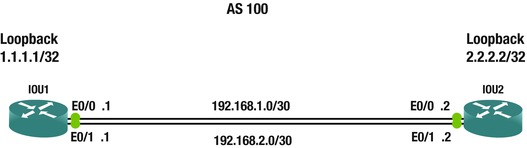
Figure 6-24. BGP routing answer diagram
IOU1(config)#int e0/0
IOU1(config-if)#ip address 192.168.1.1 255.255.255.252
IOU1(config-if)#no shut
IOU1(config-if)#int e0/1
IOU1(config-if)#ip address 192.168.2.1 255.255.255.252
IOU1(config-if)#int loopback1
IOU1(config-if)#ip address 1.1.1.1 255.255.255.255
IOU1(config-if)#router bgp 100
IOU1(config-router)#neighbor 2.2.2.2 remote-as 100
IOU1(config-router)#neighbor 2.2.2.2 update-source loo1
IOU1(config-router)#ip route 2.2.2.2 255.255.255.255 Ethernet0/0
IOU1(config)#ip route 2.2.2.2 255.255.255.255 Ethernet0/1

IOU2(config)#int e0/0
IOU2(config-if)#no shut
IOU2(config-if)#ip address 192.168.1.2 255.255.255.252
IOU2(config-if)#int e0/1
IOU2(config-if)#no shut
IOU2(config-if)#ip address 192.168.2.2 255.255.255.252
IOU2(config-if)#int loopback1
IOU2(config-if)#ip address 2.2.2.2 255.255.255.255
IOU2(config-if)#router bgp 100
IOU2(config-router)#neighbor 1.1.1.1 remote-as 100
IOU2(config-router)#neighbor 1.1.1.1 update-source loo1
IOU2(config-router)#ip route 1.1.1.1 255.255.255.255 Ethernet0/0
IOU2(config)#ip route 1.1.1.1 255.255.255.255 Ethernet0/1

BGP neighbor is 2.2.2.2, remote AS 1, internal link
  BGP version 4, remote router ID 2.2.2.2
  BGP state = Established, up for 00:03:18
  Last read 00:00:34, last write 00:00:38, hold time is 180, keepalive interval is 60 seconds
  Neighbor sessions:
    1 active, is not multisession capable (disabled)
Now you test to make sure that the BGP adjacency does not drop after you shut ports down, since you have multiple connections to both routers.
IOU1(config)#int e0/1
IOU1(config-if)#shut
*Jan  8 13:53:58.630: %LINK-5-CHANGED: Interface Ethernet0/1, changed state to administratively down
*Jan  8 13:53:59.636: %LINEPROTO-5-UPDOWN: Line protocol on Interface Ethernet0/1, changed state to down
IOU1(config-if)#do sh ip bgp neighbors
BGP neighbor is 2.2.2.2, remote AS 1, internal link
  BGP version 4, remote router ID 2.2.2.2
  BGP state = Established, up for 00:05:17

IOU1(config-if)#no shut
IOU1(config-if)#int e0/0
*Jan  8 13:54:40.657: %LINK-3-UPDOWN: Interface Ethernet0/1, changed state to up
*Jan  8 13:54:41.665: %LINEPROTO-5-UPDOWN: Line protocol on Interface Ethernet0/1, changed state to up
IOU1(config-if)#shut
IOU1(config-if)#
*Jan  8 13:54:45.978: %LINK-5-CHANGED: Interface Ethernet0/0, changed state to administratively down
*Jan  8 13:54:46.981: %LINEPROTO-5-UPDOWN: Line protocol on Interface Ethernet0/0, changed state to down
IOU1(config-if)#do sh ip bgp neighbors
BGP neighbor is 2.2.2.2, remote AS 1, internal link
  BGP version 4, remote router ID 2.2.2.2
  BGP state = Established, up for 00:05:50
Summary
This chapter discussed router configurations, covering static routing and dynamic routing protocols such as RIP, EIGRP, OSPF, and BGP. There are many routing protocols to choose from, with many advantages and disadvantages for each. Table 6-5 should help with choosing a protocol that fits your needs. Remember that EIGRP is a proprietary protocol of Cisco and can only be used with their hardware. Table 6-5 compares the differences among the dynamic protocols discussed.
Table 6-5. Routing Protocol Comparison Chart