![]()
Data Link Layer
This chapter discusses protocols associated with the data link layer. The protocols covered are Address Resolution Protocol (ARP), Reverse Address Resolution Protocol (RARP), link layer functions, Link Layer Discovery Protocol (LLDP), and Cisco Discovery Protocol (CDP). As mentioned earlier, the data link layer must ensure that messages are transmitted to devices on a LAN using physical hardware addresses, and they also must convert packets sent from the network layer, and convert them into frames to be sent out to the physical layer to transmit. The data link layer converts packets into frames, which adds a header that contains the physical hardware device of the source and the destination address, flow control, and a footer with the checksum data (CRC). We are going to dive deeply into this layer.
Protocols establish an agreed way of communicating between two systems or components. They establish a common language and specify how sessions begin and how data is exchanged. Imagine trying to play a PlayStation 3 disc in an Xbox video game console. What would the outcome be? The game is unable to play, but why? PlayStation and Xbox video game consoles each have their own established protocols that allow their games to be played on their systems. Protocols allow many different vendors to develop devices that can communicate by using a common set of rules defined by these protocols. Now let’s dive into some of the protocols used in the data link layer.
The Address Resolution Protocol (ARP)
Imagine that you are at a grocery store and have lost your child. You go to the store manager to ask to make an announcement over the PA system: “Hi, Bob. Your parent is looking for you. Please come to the front of the store.” ARP is similar, as all can hear a broadcast message—but only one recipient responds to the request. ARP is a protocol used to translate network logical addresses into link layer physical hardware addresses. In short, IP addresses are converted to MAC addresses and the translation is placed in a device’s ARP table.
When a network device receives a packet with a destination IP address on a subnet it owns, and the MAC address of the destination is not in its ARP table, the device sends out a packet of all interfaces to determine who the owner of this IP address is. The host with the corresponding IP address responds with its MAC address, and the switch annotates this in its ARP table for a faster resolution in the future. Figure 3-1 is the diagram used for the show arp command as you view the ARP table.
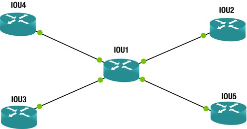
Figure 3-1. Example of an ARP table in a router
The following example Cisco command displays the ARP table of router IOU1:
IOU1#show arp
Protocol  Address          Age (min)  Hardware Addr   Type   Interface
Internet  192.168.1.1             0   aabb.cc00.0400  ARPA   Ethernet0/0
Internet  192.168.1.2             -   aabb.cc00.0100  ARPA   Ethernet0/0
Internet  192.168.2.1             0   aabb.cc00.0300  ARPA   Ethernet0/1
Internet  192.168.2.2             -   aabb.cc00.0110  ARPA   Ethernet0/1
Internet  192.168.3.1             0   aabb.cc00.0200  ARPA   Ethernet0/2
Internet  192.168.3.2             -   aabb.cc00.0120  ARPA   Ethernet0/2
Internet  192.168.4.1             0   aabb.cc00.0500  ARPA   Ethernet0/3
Internet  192.168.4.2             -   aabb.cc00.0130  ARPA   Ethernet0/3
The ARP table of the IOU1 contains the physical MAC address interface connecting the other devices and their IP addresses. This table saves time for the devices when received traffic is destined for one of these IP addresses. IOU1 no longer has to send out a broadcast requesting these IP addresses but can simply forward packets to their destinations.
Figure 3-2 shows that the workstation with IP address 1.1.1.1 needs to know which end device owns IP address 1.1.1.2. The workstation sends its request to the switch, which then sends an ARP broadcast out of its interfaces and waits for one of the end devices to respond. The workstation with IP 1.1.1.2 responds to the ARP request and sends its MAC address back to the switch. The switch creates an entry with this information in its ARP table for future reference and sends the information to the requesting workstation with IP 1.1.1.1.
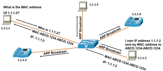
Figure 3-2. ARP request example
The Wireshark capture in Figure 3-3 displays an ARP request as a broadcast packet. The ARP reply is shown in Figure 3-4. The destination hardware address is FF:FF:FF:FF:FF:FF; it is a hardware address broadcast.
Figure 3-3. Example ARP request
In line number 292 in the Wireshark captures shown in Figures 3-3 and 3-4, you will notice that the requesting device is looking for the physical address of IP address 1.1.1.1. The end device at 1.1.1.1 responds to the ARP requests with a reply, including its MAC address in line number 293.

Figure 3-4. Example ARP reply
The Reverse Address Resolution Protocol (RARP)
RARP is a protocol used to translate physical addresses into network layer IP addresses. RARP is similar to ARP, except that a physical address is broadcast rather than an IP address. When a computer requests the IP address of a computer network, but it knows nothing but a MAC address, the client broadcasts the request, and a device that can provide the mapping of the MAC address to the computer’s IP address is identified.
The link layer is responsible for framing, addressing, synchronization, flow control, and error control. We will now further discuss key functions of the link layer.
Framing
Packets arrive from the network layer, and the data link layer encapsulates them into frames. Next, each frame is sent to the physical layer to be sent to the receiver, which receives the signals sent, bit by bit, and assembles them into frames. The frames are formatted based on the specific physical layer specification used, such as Ethernet or Wi-Fi, before being transmitted to the receiver.
Addressing
This layer is responsible for physical hardware addressing. This address is similar to your home address; in other words, the physical address is where the device resides. The physical address—called a media access control address, or MAC address—is a unique identifier assigned to network interface controller (NIC) cards on the physical network segment. MAC addresses are also known as hardware addresses, and are assigned by the manufacturer of the device.
Synchronizing
The data link layer sends frames from sender to receiver and synchronizes the two in order for the data transfer to occur. The beginning and the end of a frame can be detected by using flag fields or special synchronization fields.
Flow Control
The data link layer ensures that both the sender and the receiver exchange data at the same speed by using flow control. Flow control is necessary if both the sender and the receiver have different speed capabilities.
In the event that signals encounter a problem in transit, errors are detected and the data link layer attempts to recover data bits. This layer also provides error reporting to the transmitter or the sender of the data. Backward error correction allows the receiver to detect an error in the data received and requests the sender to retransmit the data. Forward error correction allows the receiver to detect an error in the data received and autocorrect some errors.
Figures 3-5, 3-6, and 3-7 show examples of frames with errors at the data link layer. Figure 3-5 shows a frame with a single-bit error.
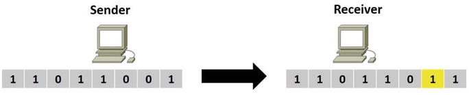
Figure 3-5. Single-bit error
Figure 3-6 shows a frame with multiple-bit errors.
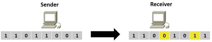
Figure 3-6. Multiple-bit errors
Figure 3-7 shows a frame with more than one consecutive bit errors, or a burst of errors.

Figure 3-7. Consecutive errors
Link Layer Discovery Protocol (LLDP)
LLDP is a vendor-neutral layer 2 protocol used by network devices advertising their identity, capabilities, and neighbors on a local area network. LLDP is similar to the Cisco proprietary protocol CDP, which is discussed later in the book. A requirement for using LLDP is to implement type-length-values (TLVs). The following TLVs are required:
- Inventory
- LLDP-MED capabilities
- Network policy
- Port VLAN ID
- MAC/PHY configuration status
- Extended power via media dependent interface (MDI)
LLDP allows management tools such as Simple Network Management Protocol (SNMP) detect and correct network misconfigurations and malfunctions. The use of LLDP is restricted to the Ethernet, Fiber Distributed Data Interface (FDDI), and token ring types of media. LLDP Media Endpoint Discovery (MED) was created by the Telecommunications Industry Association (TIA) for Voice over IP (VoIP) devices. LLDP sends advertisements to a multicast address with information about itself to neighbors, including device identifiers, versions, and port identifiers. Any device in the network is able to learn about the neighboring devices it is connected to, as advertisements are transmitted and received on all enabled and active interfaces. Also, devices can be controlled to not transmit or receive information on a per-port basis.
A network device will only transmit LLDP packets until an endpoint device transmits an LLDP-MED packet to the network device. After an LLDP-MED packet is received, the network device continues transmitting LLDP-MED packets to the endpoint device.
Class of Endpoints
LLDP-MED can support the following classes of endpoints:
- Class 1: Used for basic endpoint devices such as IP communication controllers
- Class 2: Used for endpoint devices supporting streaming media
- Class 3: Used for endpoint devices supporting IP communications, such as VoIP phones
Figure 3-8 shows a local area network (LAN) with LLDP-MED enabled.

Figure 3-8. Example of LLDP-MED messages on a LAN
LLDP Benefits
Now that LLDP has been introduced, let’s review some of the benefits of using it.
- Network management services can track network devices and determine software and hardware versions and serial numbers
- Autodiscovery of local area network policies
- Supports multivendor interoperability
- Provides MIB support
- Device location discovery supports Enhanced 911 services on VoIP devices
- Automated power management of Power over Ethernet (PoE) end devices
- Provides troubleshooting aids to detect duplex and speed issues, and communicates to phones the VLAN that they should be in
Let’s review Figure 3-9 to discuss some of the fields in the LLDP packets. LLDP uses the Ethernet as its transport protocol. You can see from the packet that the Ethernet type for LLDP is 0x88cc. LLDP Data Units (LLDPDUs) are forwarded to the destination MAC address—01:80:c2:00:00:0e, which is an LLDP multicast address, which is shown in both packet captures. Important information to note in the packet capture is the destination address, which is the LLDP multicast address. Also note the type of packet, which is LLDP is 0x88cc. You can see the MAC address of the sending device; the port that is being used, FastEthernet0/13; and the system name, S1.cisco.com; as well as the system description, including the router’s Internetwork Operating System (IOS) information and the type of device.
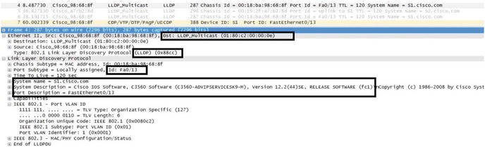
Figure 3-9. LLDP packet
All Cisco network devices running LLDP create a table of information received from neighbor devices that can be viewed using the show lldp command, as shown in Figure 3-10. The lldp run command activates LLDP. Lastly, you can see that the show lldp neighbors command displays information from devices connected to your router. The show lldp neighbors detail command displays more information about neighboring devices, as shown in the packet capture in Figure 3-9. Figure 3-10 displays the network used in our LLDP example.

Figure 3-10. LLDP network example
The following Cisco commands are an example of enabling LLDP and how to display information related to LLDP on a router or switch.
Enter configuration commands, one per line.  End with CNTL/Z.
IOU1(config)#lldp run
IOU1(config)#exit
IOU1#show lldp ?
  entry      Information for specific neighbor entry
  errors     LLDP computational errors and overflows
  interface  LLDP interface status and configuration
  neighbors  LLDP neighbor entries
  traffic    LLDP statistics
  |          Output modifiers
  <cr>

IOU1#show lldp neighbors
Capability codes:
    (R) Router, (B) Bridge, (T) Telephone, (C) DOCSIS Cable Device
    (W) WLAN Access Point, (P) Repeater, (S) Station, (O) Other

Device ID           Local Intf     Hold-time  Capability      Port ID
IOU4                Et0/0          120        R               Et0/0
IOU5                Et0/3          120        R               Et0/0
IOU7                Et1/0          120        R               Et0/0
IOU2                Et0/2          120        R               Et0/0
IOU3                Et0/1          120        R               Et0/0

Total entries displayed: 5

IOU1#show lldp neighbors detail
------------------------------------------------
Chassis id: aabb.cc00.0400
Port id: Et0/0
Port Description: Ethernet0/0
System Name: IOU4

System Description:
Cisco IOS Software, Linux Software (I86BI_LINUX-ADVENTERPRISEK9-M), Version 15.4(1)T, DEVELOPMENT TEST SOFTWARE
Technical Support: http://www.cisco.com/techsupport
Copyright (c) 1986-2013 by Cisco Systems, Inc.
Compiled Sat 23-Nov-13 03:28 by prod_rel_tea

Time remaining: 112 seconds
System Capabilities: B,R
Enabled Capabilities: R
Management Addresses:
    IP: 192.168.1.1
Auto Negotiation - not supported
Physical media capabilities - not advertised
Media Attachment Unit type - not advertised
Vlan ID: - not advertised

------------------------------------------------
Chassis id: aabb.cc00.0500
Port id: Et0/0
Port Description: Ethernet0/0
System Name: IOU5

System Description:
Cisco IOS Software, Linux Software (I86BI_LINUX-ADVENTERPRISEK9-M), Version 15.4(1)T, DEVELOPMENT TEST SOFTWARE
Technical Support: http://www.cisco.com/techsupport
Copyright (c) 1986-2013 by Cisco Systems, Inc.
Compiled Sat 23-Nov-13 03:28 by prod_rel_tea

Time remaining: 104 seconds
System Capabilities: B,R
Enabled Capabilities: R
Management Addresses:
    IP: 192.168.4.1
Auto Negotiation - not supported
Physical media capabilities - not advertised
Media Attachment Unit type - not advertised
Vlan ID: - not advertised
 (Output Omitted)
Total entries displayed: 5
As you can see from the LLDP output, a tremendous amount of information can be gathered about your neighbors. The interface your neighbor is using to connect to you and your interface is listed, including the neighbor’s IP address. System information such as the neighbor’s hostname and IOS version is also displayed. This information can be very helpful when troubleshooting physical connectivity issues.
Cisco Discovery Protocol (CDP)
As mentioned, CDP is the Cisco proprietary version of LLDP. It is also used to transmit and receive information about Cisco directly connected neighbors. Cisco transmits CDP advertisements to multicast address 01:00:0c:cc:cc:cc out of every enabled interface. CDP advertisements are sent every 60 seconds by default. All Cisco network devices running CDP create a table of information received from neighbor devices that can be using the show cdp command, as shown in Figure 3-11. The cdp run command enables CDP, and the CDP timer command changes the rate CDP packets are transmitted from the default 60 seconds to 30 seconds. Lastly, you can see the show cdp neighbors and show cdp neighbors detail command displays information from the devices connected to IOU1. Figure 3-11 displays the network used in our example.

Figure 3-11. Network diagram used in a CDP example
The following Cisco commands show an example of enabling CDP and how to display information related to CDP on a router or switch.
IOU1(config)#cdp run
IOU1(config)#cdp ?
  advertise-v2  CDP sends version-2 advertisements
  holdtime      Specify the holdtime (in sec) to be sent in packets
  run           Enable CDP
  timer         Specify the rate at which CDP packets are sent       (in sec)

The show cdp command can display information on the router related to CDP.

IOU1#show cdp ?
  entry      Information for specific neighbor entry
  interface  CDP interface status and configuration
  neighbors  CDP neighbor entries
  tlv        CDP optional TLVs
  tlv-list   Information  about specific tlv list
  traffic    CDP statistics
  |          Output modifiers
  <cr>

The show cdp interface command displays cdp information for a particular interface.

IOU1#show cdp interface e0/0
Ethernet0/0 is up, line protocol is up
  Encapsulation ARPA
  Sending CDP packets every 60 seconds
  Holdtime is 180 seconds
IOU1#show cdp neighbors
Capability Codes: R - Router, T - Trans Bridge, B - Source Route Bridge
                  S - Switch, H - Host, I - IGMP, r - Repeater, P - Phone,
                  D - Remote, C - CVTA, M - Two-port Mac Relay

Device ID        Local Intrfce     Holdtme    Capability  Platform  Port ID
IOU3             Eth 0/1           131              R B   Linux Uni Eth 0/0
IOU2             Eth 0/2           126              R B   Linux Uni Eth 0/0
IOU7             Eth 1/1           136              R S   Linux Uni Eth 0/0
IOU6             Eth 1/0           140              R S   Linux Uni Eth 0/0
IOU5             Eth 0/3           152              R B   Linux Uni Eth 0/0
IOU4             Eth 0/0           170              R B   Linux Uni Eth 0/0

Total cdp entries displayed : 6

The show cdp neighbors detail displays detail information about neighbors learned via cdp.

IOU1#show cdp neighbors detail
------------------------------
Device ID: IOU3
Entry address(es):
  IP address: 192.168.2.1
Platform: Linux Unix,  Capabilities: Router Source-Route-Bridge
Interface: Ethernet0/1,  Port ID (outgoing port): Ethernet0/0
Holdtime : 127 sec

Version :
Cisco IOS Software, Linux Software (I86BI_LINUX-ADVENTERPRISEK9-M), Version 15.4(1)T, DEVELOPMENT TEST SOFTWARE
Technical Support: http://www.cisco.com/techsupport
Copyright (c) 1986-2013 by Cisco Systems, Inc.
Compiled Sat 23-Nov-13 03:28 by prod_rel_team

advertisement version: 2
Duplex: half
Management address(es):
  IP address: 192.168.2.1

-------------------------
Device ID: IOU2
Entry address(es):
  IP address: 192.168.4.1
Platform: Linux Unix,  Capabilities: Router Source-Route-Bridge
Interface: Ethernet0/2,  Port ID (outgoing port): Ethernet0/0
Holdtime : 178 sec

Version :
Cisco IOS Software, Linux Software (I86BI_LINUX-ADVENTERPRISEK9-M), Version 15.4(1)T, DEVELOPMENT TEST SOFTWARE
Technical Support: http://www.cisco.com/techsupport
Copyright (c) 1986-2013 by Cisco Systems, Inc.
Compiled Sat 23-Nov-13 03:28 by prod_rel_team

advertisement version: 2
Duplex: half
Management address(es):
  IP address: 192.168.4.1
        (Output Omitted)
As you can see in Figure 3-12, a device is sending its information to its neighbor connected to interface FastEthernet0/0, including its IP address, Cisco IOS version, duplex setting, and the type of Cisco device. In this case, the sending device is a Cisco 3745 running IOS version 12.4.

Figure 3-12. Example of a CDP packet captured with Wireshark
LLDP and CDP are protocols that ease network LAN management by allowing devices to exchange network policy information. These protocols simplify the task of finding errors due to misconfigurations, from duplex mismatches to VLAN misconfigurations.
Summary
This chapter discussed the importance of protocols and how they allow devices from different vendors to communicate. One of the key protocols at the data link layer is ARP. Switches use ARP to determine IP addresses by sending a broadcast to each device in its broadcast domain. The sender responds with its MAC address, allowing the switch to place the combination of IP address and MAC address in its ARP table for faster processing in the future. This chapter also covered link layer functions, including framing and error control. You saw how the power of ARP, CDP and LLDP. All of these protocols can help troubleshoot whether or not your neighbors are communicating with your router, and this information can be reviewed to ensure that you are connected to the correct device.