![]()
Advanced Security
Before we start, let’s be realistic about the expectations that there cannot be a 100% secure information system (IS). There are too many factors to evaluate that are out of your control, including the human factor. Therefore, security is more of a trade-off art of balancing risk. It goes without saying that complex systems with millions of lines of code are harder to secure than simpler systems. Usually, there are oppositely proportional factors that contribute to the security of a system, such as flexibility vs. narrow scope, and factors that are directly proportional to security of the system, such as the time invested securing the system. However, factors that tend to increase the security of the system also tend to increase cost, and so a careful balance must be found between time, cost, flexibility, and security.
Information systems (IS) managers and engineers manage the risk to the information system by weighing the vulnerabilities against the probability that the vulnerability can be reasonably exploited, thus realizing the threat. Note that we said “reasonably exploited,” because that’s what an individual attacker might consider as unreasonable expenditure of resources to exploit the vulnerability; a nation state actor may consider it reasonable.
When addressing security in an IS, you must consider the various levels of interaction that the IS has within the physical and virtual (or logical) environments. This is the hard part of security because different bodies of knowledge are required to achieve good security in business IS, especially those business sectors regulated by laws. Table 16-1 provides a quick look at all the security aspects to consider for a web application by using the OSI layer reference model as guide.
Table 16-1. OSI Layer Attacks
|
OSI Layer |
Possible Attack Scenarios |
|---|---|
|
Physical (e.g., fiber, Ethernet cables or Wi-Fi) |
Fiber or Ethernet cables are tapped, spoofed Wi-Fi station intercepting business traffic. |
|
Data Link |
MAC and ARP spoofing address of legitimate systems. Highjacking L2 control protocols such as STP, VTP, LLDP, CDP, LACP, DTP. Flooding and other resource exhaustion attacks (denial of service). |
|
Network |
IP spoofing. Denial of Service attacks. High jacking routing and other control protocols such as HSRP, BGP, OSPF, RIP. |
|
Transport |
Denial of service attacks. |
|
Session |
Session highjacking (replay attacks), authentication attacks. |
|
Presentation |
Encoding attacks, mimetype spoofing, file extension spoofing. |
|
Application |
Web server directory traversals, encoding, invalid inputs, SQL injections. |
If it isn’t enough to consider the security of your own application, you must also consider the full stack or system dependency vulnerabilities, such as the programming language, operating system, database, web server, linked and libraries, among other common application dependencies. The great number of dependencies in modern applications increases the probability of a vulnerability, making it easy to realize how daunting the work of a security team is.
A good network security team is composed from physical security personnel, network personnel, application developers, deployment and maintenance teams, and management. The security team must be highly integrated and able to operate over any administrative boundaries that separate its members. In order to have a chance at staying ahead of the attackers, the entire IT staff must be security conscious. Also, management has to be supportive of the security efforts. It is not enough to secure a network if an attacker can manage to subvert the application and steal the business data, especially when the loss of the data could leave the business subject to litigation and/or penalties.
For the purpose of this book, we will focus on the network security; however, we encourage you to read further1 into the encompassing aspects of a complete security solution. Let’s start by exploring L2 control plane security and how the control protocols can give an attacker control of the network.
In the following sections, we attempt to cover portions of network security in three aspects: design, protocols, and testing tools.
Spanning tree is one of the most common layer 2 control protocols, usually enabled by default. It is also the most commonly misconfigured control protocol in networking. When we refer to STP, we are including all the implementations in a generic fashion, unless otherwise specified. We recommend that you use rapid spanning tree implementations with fast convergence, such as RPVST or MSTP.
In today’s networks, it is common to use VLANs to break up traffic groups, usually mapping those groups to teams, locations, or clusters of systems. The main problems with STP are (a) the resulting topology from non-deterministic configuration, and (b) the lack of security in the BPDU exchanges. A common trade-off observed when using STP is the utilization of redundant paths vs. loop avoidance; therefore, careful planning must be taken when planning the STP topology to avoid causing a layer 2 topology loop. For more information about L2 design trade-offs, we suggest Designing Cisco Network Service Architectures2 and for a detailed explanation of the various STP implementations in CCIE Practical Studies.3
First, let’s keep in mind that the purpose of STP is to elect a root bridge and build loop-free paths to the root bridge. It’s important to consider the previous sentence for a moment, since from the sense of security, it means that if an attacker highjacks the STP process, he can steer traffic to a bridge of his choosing.
The requirements determine the STP topology, but bear in mind that some topologies are more problematic than others. Let’s start with the requirement to span VLANs over multiple access switches; that is, for example, VLAN 500 and its defining attributes must be present in all access switches in the diagram shown in Figure 16-1. A VLAN spanning topology is the most difficult to secure since it means that the layer 2 boundary extends to the distribution switches and the traditional layer 2 data exchanges and control protocols without an overlaying security mechanism. Also, it offers no protection against reconnaissance, and in some cases, no authentication against spoofing. Figure 16-1 is the reference design in many of the following examples.
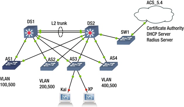
Figure 16-1. Spanning VLAN topology spanning layer 2 to the distribution layer
As illustrated in Figure 16-1, the topology that allows spanning VLAN 500 across multiple access switches results in a requirement to implement layer 2 up to the distribution switches, and thus requiring a layer 2 trunk between the distribution switches. Throughout this section, we refer to this topology to illustrate the attacks possible and the importance of proper and deterministic network configuration. Notice that we mentioned deterministic when referring to network configuration; this is because there are default behaviors built into the implementation of protocols, especially those that autonegotiate by different vendors. But whenever possible, the technician or engineer should make the settings explicit in the configuration (not implicit), and thus avoid unexpected behaviors or highjacking of the protocol by a nefarious individual.
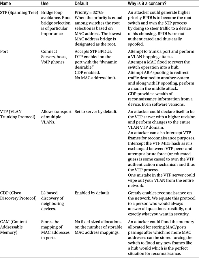
Before heading into the security aspect, let’s make a list of the default settings in a Cisco device, for example, that may cause headaches later. Table 16-2 lists the default settings and security concerns associated with them.
Table 16-2. Cisco Security Concerns
Before proceeding, a word of caution on the amount of information that your network reveals about itself with ease-of-use protocols such as CDP. Ease-of-use protocols usually carry the background overhead of sharing too much information that is collected in the reconnaissance phase to better target an attack. The same can be said when leaving your network to run in a non-deterministic way. Yes, your STP process may still be running, but is your traffic flowing efficiently? And if someone alters the optimal flow in a non-deterministic design, how would you find out?
Now let’s proceed to the security aspect relevant to this section. Following the design in the Figure 16-1, we want to set up a deterministic spanning tree design that is also secure from attackers. At this point, you may be asking yourself: What can an attacker do to my STP? You can find a few hints in Table 16-3.
Table 16-3. Possible Network Attacks Using Yersinia
The virtual machine at the bottom the diagram in Figure 16-1 named Kali is simulating an attacker’s computer. It’s running the famed penetration testing Debian distribution, Kali. First, let’s discuss the importance of securing the spanning protocol to avoid an attacker gaining control, becoming the root bridge and steering traffic to a point of the attacker’s choosing, but also manipulating the frame-forwarding topology to his advantage. For this demonstration, let’s use a tool named Yersinia, which is part of the vulnerability analysis suite of Kali. You can use Yersinia4 with a GTK-based GUI (yersinia –G) or a text-based GUI (yersinia –I). We prefer the text-based GUI since it is more stable, but recommend new users start with the GTK GUI for familiarization.
The simplest STP attack with Yersinia to perform on the spanning tree protocol is to claim to be the root bridge by sending higher-priority BPDUs to the STP process. To perform these attacks, the connected port must not filter BPDUs, so that the attacker can perform reconnaissance and proceed to craft BPDUs that ensure to be of higher priority than any other in the STP process, and thus become the root bridge. The beauty of becoming the root bridge is the possibility to steer all traffic toward the attacking system and gain more reconnaissance information for other attacks. Figure 16-2 shows the Yersinia GTK GUI used for the attack.

Figure 16-2. Yersinia GTK GUI
Figure 16-3 displays the current root bridge before the attack is started.

Figure 16-3. DS1 is initially the root bridge
Figure 16-4 shows the Yersinia GTK GUI as the STP attack is started.
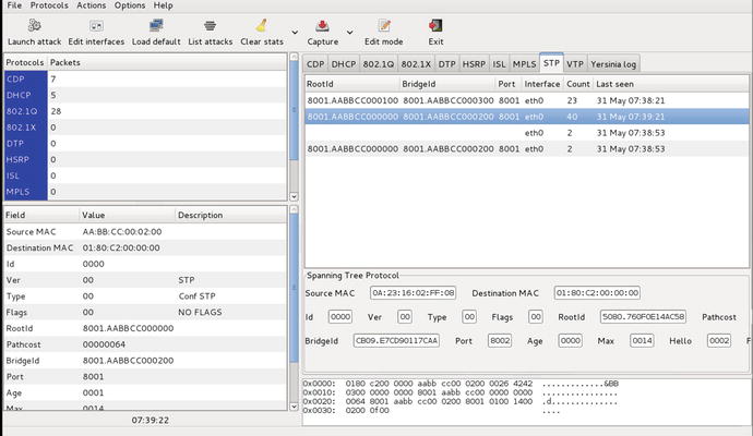
Figure 16-4. Yersinia GTK GUI showing a STP attack to become root bridge is initiated
Figure 16-5 shows the new root bridge after the attack.

Figure 16-5. DS1 is no longer the root bridge, instead it is the attacker’s system connected to port Eth0/1
These series of illustrations show how easy it is to perform a spanning tree attack on an unprotected spanning tree process. Before beginning the steps to protect the spanning tree, let’s consider how the topology is designed with the requirement to span the VLANs over the access switches, but also the fact that there is a level of redundancy at the distribution switch. For this scenario, let’s choose the following design guidelines.
- Use per VLAN spanning tree to load balance the spanning tree between distribution switches DS1 and DS2. For this example, use 802.1D MSTP since it is an IEEE standard and supported by many vendors.
- Deterministically make the distribution switches DS1 and DS2 the root bridges and make them alternates of each other for those VLANs that they are not the root bridge. DS1 is the root for VLANs 100, 200, and 500 and the secondary root for VLANs 300 and 400; while DS2 is the root bridge for VLANS 300 and 400 and the secondary root for VLANs 100, 200, and 500.
- The native VLAN on every switch is changed to VLAN 500. Instance 0 of the MSTP runs under VLAN 500 and not under the default VLAN 1.
 Note To make sure that your MSTP configuration does not encounter issues, you must ensure that all MSTP switches in a region have the same native VLAN configured, since instance 0, or Mono Spanning Tree, runs on the native VLAN; for this example, that is VLAN 500.
 - Secure the distribution switches from unwanted BPDUs that would cause them to lose root-bridge status.
- Use the STP toolkit from Cisco.
Note Rapid Spanning Tree (RSTP)–based implementations already include an implementation of UplinkFast, BackboneFast, and PortFast.
- UplinkFast and BackboneFast to speed up STP convergence after a link failure.
- PortFast toward host-only ports to speed up the time to forwarding state.
- RootGuard and BPDU guard against unwanted BPDUs on designated ports.
- UDLD, LoopGuard, and Etherchannel guard should be used to prevent the absence of BPDUs caused by unidirectional link failure from causing loops.
- Define an err-disable condition to shut down ports in case a BPDU is received in a host port.
- Use descriptions in the ports to clearly define host ports from uplink ports.
- Define a BitBucket VLANs (for this example, VLAN 600) and assign all non-used ports to VLAN 600.
Note All ports are assigned to the default VLAN 1, and unless changed, they are also forwarded via unpruned trunks to other switches.
- Define all non-uplink ports to be the host port via the Cisco Host macro.
Note Avoid daisy chaining access layer switches; it is just a bad practice and reduces the overall reliability.
- Explicitly define the VLANs that should be allowed in each area and through trunk links.
- Deterministically and explicitly define (avoid auto settings) all trunk links and LACP aggregation link. Use LACP to aggregate links between DS1 and DS2 and set up a trunk on the aggregate.
- Ensure that the MAC address table cannot be flooded.
Figure 16-6 shows the methods used for STP security.

Figure 16-6. Application of STP protection features for the MST deployment
Figure 16-7 is used for configuration and to illustrate security issues.

Figure 16-7. Design guidelines visualization
The following is a configuration based on Figure 16-7. It addresses requirements 1 through 11 for the distribution switches. Lines beginning with ! denote comments that explain the configuration entries that pertain to the aforementioned requirements.
vtp domain SEC_LAB
! Protect against dynamic changes in the VLAN infrastructure. All VLAN changes
! must be locally at the switch.
vtp mode transparent
! IEEE RSTP implementation, MST, enable as the STP protocol to use
spanning-tree mode mst
! Protect against the loops caused by one way communications
spanning-tree loopguard default
spanning-tree extend system-id
spanning-tree pathcost method long
! MSTP Parameters. VLAN 100 and 200 run on insttance 1, VLAN 300 and 400
! instance 2 and VLAN 500 will run, replacing VLAN1, in the default MST
! intance 0.
spanning-tree mst configuration
 name SECURING
 revision 1
 instance 1 vlan 100, 200
 instance 2 vlan 300, 400
! Specify root role for MST instance 0 and 1
spanning-tree mst 0-1 priority 0
! Specify backup root role for MST instance 2
spanning-tree mst 2 priority 4096
! VLAN Definitions.
vlan 100,200,300,400
vlan 500
 name NATIVE
! BitBucket VLAN is the default VLAN for any port otherwise configured.
! Replaces the default VLAN 1 as the default assignment VLAN for all ports
vlan 600
 name BitBucket
!
interface Port-channel1
 switchport
 switchport trunk encapsulation dot1q
! Changing the native VLAN. The reason for this is two fold. 1) avoid double
! encapsulation attacks (VLAN hopping)and 2) avoid allowing access to all
! default port to the trunk since by default all ports are part of the native
! VLAN 1.
 switchport trunk native vlan 500
!Pruning only necessary VLANs
 switchport trunk allowed vlan 100,200,300,400,500
! Deterministic Trunk settings, no DTP negotiation frames are sent.
 switchport mode trunk
 ip dhcp snooping trust
![]() Note It is worth noting that if trunking is dependent on DTP negotiations, the VTP domains must match between the peers. DTP is used when a ports is set up for either dynamic desirable or dynamic auto.
Note It is worth noting that if trunking is dependent on DTP negotiations, the VTP domains must match between the peers. DTP is used when a ports is set up for either dynamic desirable or dynamic auto.
interface Ethernet0/0
 switchport trunk encapsulation dot1q
 switchport trunk native vlan 500
 switchport trunk allowed vlan 100,200,300,400,500
 switchport mode trunk
 duplex auto
 ! Determinsitic LACP setting no LACP frames sent, mode on.
 channel-group 1 mode on
![]() Note Some virtual switches do not implement LACP; therefore, to establish an Etherchannel with such devices, “mode on” must be used.
Note Some virtual switches do not implement LACP; therefore, to establish an Etherchannel with such devices, “mode on” must be used.
 ip dhcp snooping trust
!
interface Ethernet0/1
 switchport trunk encapsulation dot1q
 switchport trunk native vlan 500
 switchport trunk allowed vlan 100,500
 switchport mode trunk
 duplex auto
! Guard root, in this case distribution, switches from higher priority BPDUs
 spanning-tree guard root
!
interface Ethernet0/2
 switchport trunk encapsulation dot1q
 switchport trunk native vlan 500
 switchport trunk allowed vlan 200,500
 switchport mode trunk
 duplex auto
 spanning-tree guard root
!
interface Ethernet1/1
 switchport trunk encapsulation dot1q
 switchport trunk native vlan 500
 switchport trunk allowed vlan 300,500
 switchport mode trunk
 duplex auto
 spanning-tree guard root
!
interface Ethernet1/2
 switchport trunk encapsulation dot1q
 switchport trunk native vlan 500
 switchport trunk allowed vlan 400,500
 switchport mode trunk
 duplex auto
 spanning-tree guard root
!
interface Ethernet2/0
 switchport trunk encapsulation dot1q
 switchport trunk native vlan 500
 switchport trunk allowed vlan 100,200,300,400,500
 switchport mode trunk
 duplex auto
 channel-group 1 mode on
 ip dhcp snooping trust
Now let’s consider the commands to satisfy the design requirements for the exercise from the perspective of the access layer switches.
vtp mode transparent
!
spanning-tree mode mst
! Any PortFast port is by default enabled with BPDU Guard. This is accompanied
! by defaulting all host ports to portfast. If the port receives a BPDU it
! will shutdown under the current settings. Safer that way.
spanning-tree portfast bpduguard default
spanning-tree extend system-id
!
spanning-tree mst configuration
 name SECURING
 revision 1
 instance 1 vlan 100, 200
 instance 2 vlan 300, 400
!
vlan internal allocation policy ascending
!
vlan 300,500
!
vlan 600
 name BitBucket
!
interface Ethernet0/1
 switchport trunk encapsulation dot1q
 switchport trunk native vlan 500
 switchport trunk allowed vlan 300,500
 switchport mode trunk
 duplex auto
!
interface Ethernet0/3
! An unused port assigment to the Bitbucket VLAN 600
 switchport access vlan 600
 switchport mode access
 shutdown
 duplex auto
 spanning-tree portfast
!
interface Ethernet1/1
 switchport trunk encapsulation dot1q
 switchport trunk native vlan 500
 switchport trunk allowed vlan 300,500
 switchport mode trunk
 duplex auto
!
interface Ethernet1/2
 switchport access vlan 600
 switchport trunk encapsulation dot1q
 switchport trunk native vlan 500
 switchport trunk allowed vlan 100,200,300,400,500
 switchport mode trunk
 shutdown
 duplex auto
!
interface Ethernet3/2
 description ATTACKERs port
 switchport access vlan 300
 switchport mode access
 duplex auto
! A host port setup as portfast
 spanning-tree portfast
Table 16-4 lists summaries and explanations of switch commands.
Table 16-4. Summary and Explanation of Commands
|
Concern/Attacks |
Command |
Description |
|---|---|---|
|
Protecting a root bridge from higher BPDUs |
spanning-tree guard-root spanning-tree mst <instance> priority |
Must be set in the planned root bridges at every port where there is a chance of receiving a higher BPDU. Deterministically assigning the root priority to the intended bridges. |
|
Portfast |
spanning-tree portfast |
Reduces the ports transition time to the forwarding state. Must be used only in a host port. |
|
spanning-tree portfast bpduguard |
Since portfast bypasses the listening and learning states, must use bpduguard to protect the port from bdpus. | |
|
VLAN Hopping |
switchport mode access switchport trunk native vlan |
The combinations of a host port set only to access without possibility to trunk and changing the native VLAN in trunks eliminates the possibility of VLAN hopping. Also changing the native VLAN and assigning ports to a bit bucket by default reduces the risk of an attacker gaining advantage of a port turn on by mistake, since a more complex series of configurations commands will be required to enable the port and assign it to a valid VLAN. |
|
DoS against the STP process |
switchport trunk allowed vlans spanning-tree portfast spanning-tree portfast bpduguard |
Limit the VLANs to those actively being used and managed. Portfast and portfast bpduuard protect host ports from receiving BPDUs. |
|
MAC flooding |
Limit the number of MAC addresses on the port. 1 for hosts and 3 for hosts connected to VoIP phones. | |
|
Reconnaissance and Spoofing of control protocols |
switchport mode trunk channel-group mode on |
Setting the mode trunk on both end of the trunk disables negotiation and DTP frames from been sent. If unauthenticated protocols are used for negotiation, those frames can be captured and replayed with a different purpose. Autonegotiation also leaves room for network to behave in a non-deterministic way at some point in time when the auto negotiation produces unintended results. Setting the LACP mode to on disables LACP negotiation and negotiation frames from been sent. |
|
Unexpected consequences of unidirectional links |
spanning-tree loopguard default |
When a port in a physically redundant topology stops receiving BPDUs the result is a topology change since the port STP process will consider the topology to be loop free. |
There are more conditions covered later in this chapter, including IP and MAC spoofing, MAC flooding, and authentication mechanisms.
Post Configuration Attack Results
All right, so we configured the basics for our reference topology; however, there is still a lot more to do. Granted that a second attack on STP from the access layer perspective will result in a port shutdown (port level attack) or switch to isolation (trunk level attack). Next, you will find a step-by-step guide on testing the design with Yersinia.
Let’s move to the results of the attack, using Figures 16-8 and 16-9.

Figure 16-8. State prior to the second attack
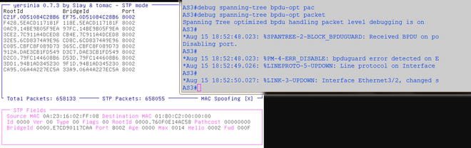
Figure 16-9. The STP attack is thwarted and the attacker’s port is placed in errdisable and shutdown
The following is the attack’s process guide.
- Start Yersinia, yersinia –I or yersinia –G.
- Start Wireshark, Ettercap, or tcpdump for an easier visualization of frames and packets. Either from the command line or navigating under Applications
 Sniffing & Spoofing.
 - Study the STP BPDUs from the root device to get advance knowledge on how to make the attack most effective (see Figure 16-9). Hint: You can use the “stp” filter in the Wireshark filter entry.
- Press G on the Yersinia text GUI for a list of supported protocols, or navigate to the STP section in the GTK GUI.
- In this case, you can attempt to use a lower MAC address since the priority is already at the lowest, zero. You need the values captured in Wireshark for the (a) Protocol Identifier, (b) Protocol Version, (c) BPDU type, (d) BDPU Flags, (e) Port identifier, (f) root identifier and bridge identifier fields (see Figure 16-10).
- Select the attack. Of course, since we have been diligent to protect the STP against unwanted BPDUs, neither the attack to claim any role nor a DoS attempt on the STP succeeded.
Figure 16-10 shows a BDPU Wireshark packet capture.
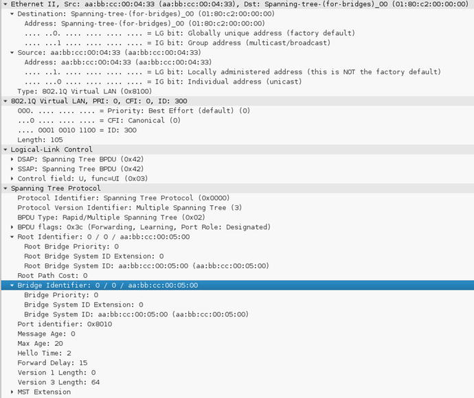
Figure 16-10. The Wireshark captured BPDU shows the Root Bridge identifier MAC address preceded by the Bridge priority
Figure 16-11 displays the BDPU attack while using Yersinia.

Figure 16-11. Using the text GUI of Yersinia to craft the attack’s BPDU by entering the relevant values learned from the reconnaissance. Press F9 (STP mode) , then press E (Edit BPDU), and then press X for attack selection
Figure 16-12 shows the STP attack menu.
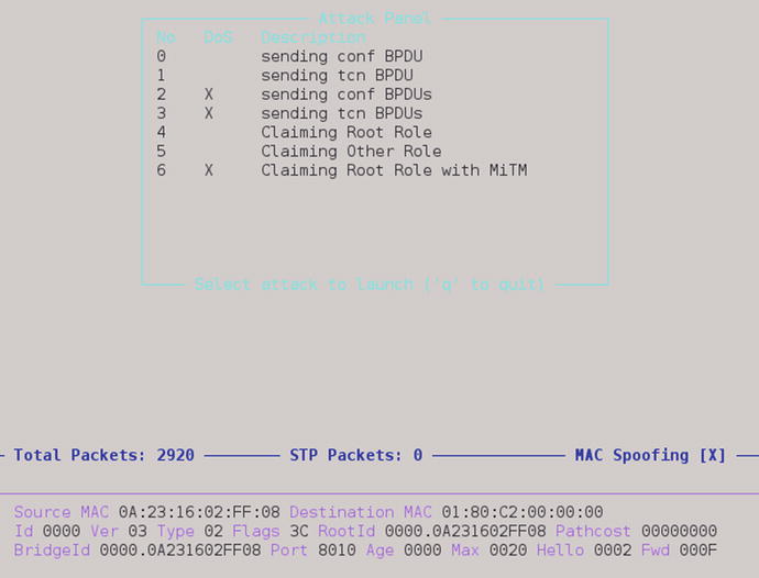
Figure 16-12. STP attack menu
Figure 16-13 shows running STP attack.

Figure 16-13. List ongoing attacks by pressing L
Securing Your Trunks and Ports
Trunks are essential since they carry the bulk of VLAN traffic between switches in a layer 2 topology. The default port settings (dynamic desirable) in access switches, allows the switch port to trunk with any trunk-requesting host. The trunk negotiation happens via the exchange of DTP (Dynamic Trunking Protocol) packets. Allowing hosts to trunk is generally a bad thing unless your host happens to be hosting a virtual switch and multiple virtual machines that belong to various VLANs. For this scenario, we have to modify one of the ports on the AS3 access switch to be in default configuration state. The attacker will trunk the port and attempt to obtain information about other VLANs in the layer 2 topology. The topology remains unchanged, as described in Figure 16-7. Note that explicitly specifying a port as PortFast will thwart not only DTP attacks, but also STP attacks since BPDU Guard works on ports enabled with PortFast, and you can’t trunk with a PortFast port. Figures 16-14, 16-15, and 16-16 are images from attacks on a misconfigured port and the attacks that followed.

Figure 16-14. Attacker trunks on port Eth0/0 setup as “dynamic desirable”
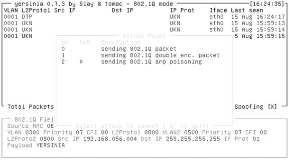
Figure 16-15. Attack options for 802.1Q
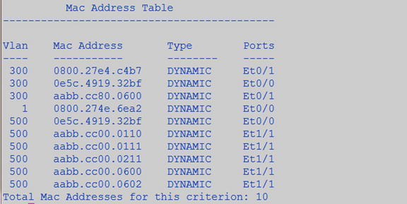
Figure 16-16. The attacker (port Eth0/0) can choose a MAC to spoof per VLAN and is participating in multiple VLANs: 1,300 and 500
You are not done yet—there still many other vectors of attack. Let’s explore attacks on the switch resources such as the MAC table. To the effect of protecting the trunk and port, let’s start with the portfast and bpduguard command in conjunction with port security with the max MAC address entries of 1 for host and 3 for VoIP phones with integrated switch to protect against MAC spoofing and MAC address table flooding. The images that follow are an example of what happens when the MAC address table is not secured by limiting MACs per port or by limiting the size of the MAC address table itself. For the attack on the MAC address table, we used a tool called Ettercap, which contains a plug-in capable of generating random MAC addresses. Figure 16-17 shows the Ettercap tool that used in the next scenario.
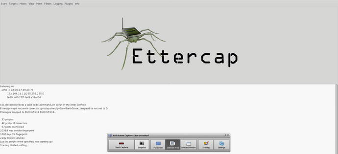
Figure 16-17. Ettercap GUI
Figure 16-18 is the diagram used for the MAC flooding scenario.

Figure 16-18. Diagram of the MAC flood scenario
Figure 16-19 shows the current ARP table before the attack.
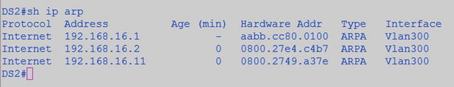
Figure 16-19. State of registered IP and MACs before the MAC flooding attack
Figure 16-20 shows the random MAC generator plug-in.
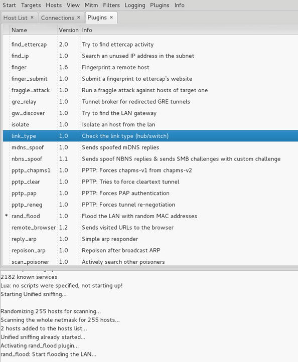
Figure 16-20. Selecting the random MAC generator plug-in, rand_flood
Do the following to perform the simple MAC flooding attacks.
- Start Ettercap.
- Select Sniff Unified Sniffing.
- Plugins Load Plugins ec_rand_flood.so.
- Start Start Sniffing (watch the fun).
Figure 16-21 shows the effects of a MAC address flooding attack.
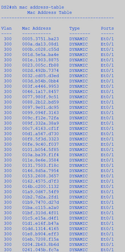
Figure 16-21. Effects of the MAC flooding by the attacker Kali. Eventually this switch turns into a nice HUB
Figure 16-22 shows the number of registered MAC address on AS3 and DS2, while the MAC flooding attack runs.
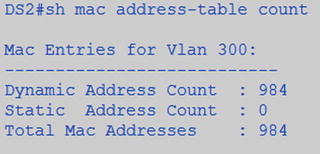
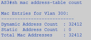
Figure 16-22. Number of registered MAC address at AS3 and DS2 during the few seconds the MAC flood ran
Figure 16-23 shows Wireshark’s frame view during the attack.

Figure 16-23. Wireshark’s frames view during the MAC flooding
We now introduce port-security based MAC address limits and reinitiate the attack.
interface Ethernet3/3
 description ATTACKERs port
 switchport access vlan 300
 switchport mode access
switchport port-security  Defaults to a maximum 1 mac addresses and to errdisabled on error.
 duplex auto
 spanning-tree portfast
Figure 16-24 shows an err-disabled port on AS3.

Figure 16-24. Effects of the MAC flooding attack when port-security is set with a limit of one MAC address
So far, we have presented attacks on the layer 2 control protocols—STP and DTP—and attacks on resources and protocols. If you think that we are done securing the network, in fact we are far from it. We have secured the STP process and the MAC address table, now we need to focus on spoofing attacks. Although we have set port security, an attacker can spoof the MAC address and gain access to the network. The best way to ensure that the MAC address identifying a host belongs to an authorized user is by using port-based 802.1x authentication.
There are various methodologies to implement 802.1x, but in this example, we are going to choose the hardest and most secure: EAP-TLS. EAP-TLS requires extensive supporting infrastructure, as discussed in Table 16-5. The benefit of using 802.1x is that until the client is authenticated, only the Extensible Authentication Protocol over LAN (EAPOL) frames are forwarded by the port (see Figure 16-24). Even if the attacker knows which MAC to spoof, he would not gain access unless he can obtain (a) the signed certificate identifying the client and sign by the Certificate Authority, (b) have the user’s private key, and (c) have the private key password to decrypt the private key used in the Transport Layer Security (TLS) tunnel establishment. Therefore, even when the port is enabled, it’s been defaulted to the BitBucket VLAN 600 unless the client connected to the port is properly authenticated. Let’s take a look at the components needed to build the 802.1x architecture in Figure 16-25. Table 16-5 displays the components of the EAP infrastructure.
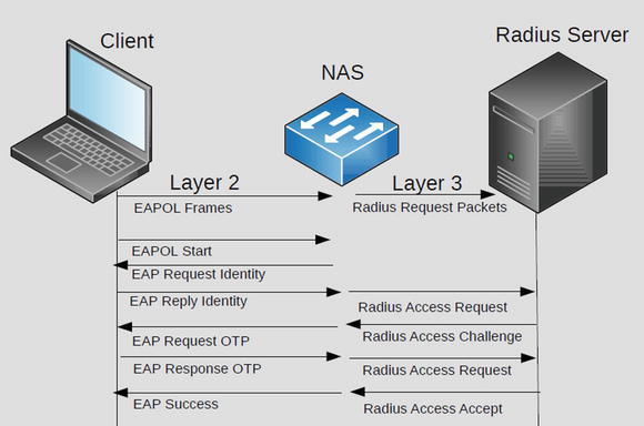
Figure 16-25. 802.1x authentication
Table 16-5. Components of a RADIUS Implementation
To keep things simple rather than having a dedicated certificate authority, we will make the RADIUS server the certificate authority. It is recommended that when you roll out a certificate authority server, it should be secured and dedicated only to this function; any other non-supportive functions should be disabled. We are going to use a Cisco ACS 5.4 server to perform the RADIUS and CA functions, and in later chapters, TACACS server functions too. The first task is to set the server certificate, as shown in Figure 16-26.

Figure 16-26. Options for the RADIUS server certificates
For the purpose of the following demonstration, let’s use a self-signed certificate by the server. Another option is to use OpenSSL (see the “Examples Using OpenSSL to Generate Signed Certificates” section) to do all the certificate operations, from requests to signing.
To enable the ACS to function as a CA (certificate authority), you have to import the ACS certificate into the certificate authorities section and allow duplicate certificates, as illustrated in Figure 16-27.
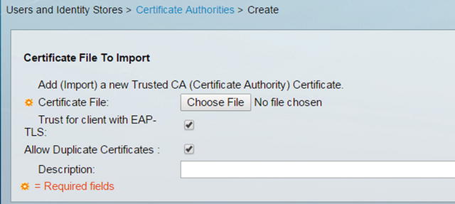
Figure 16-27. Importing a CA certificate into Cisco ACS
Figure 16-28 shows the verification of the CA.

Figure 16-28. Verify the CA
Next, you need to prepare the NAS (AS3 access switch) profile in the RADIUS server, as shown in Figures 16-29 and 16-30. Also, it is important to note that since the NAS is acting as a middleman to translate EAP messages into RADIUS messages, the NAS needs to have a virtual interface with an IP.

Figure 16-29. NAS/AAA clients listing
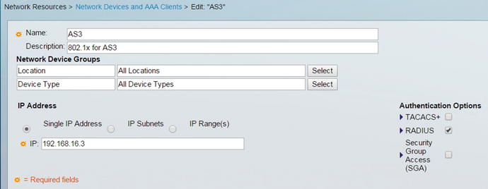
Figure 16-30. NAS/AAA client settings
Next, create a user profile for the users to be authenticated in the local identity store, as shown in Figures 16-31 and 16-32. You can also use an LDAP server or Active Directory, but for the purpose of a simple example, let’s use the local store.
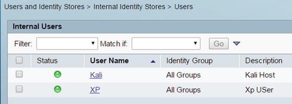
Figure 16-31. User listings
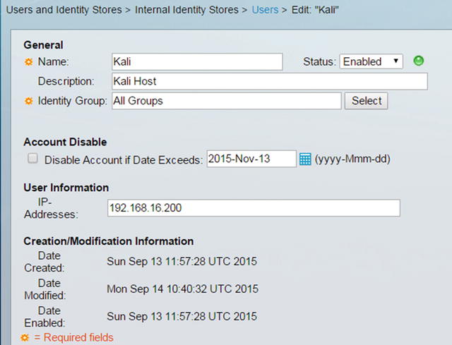
Figure 16-32. Local store user settings
Next, set up the authentication profile for the use of certificates to match the CN (Common Name) field of the certificate, as shown in Figure 16-33.
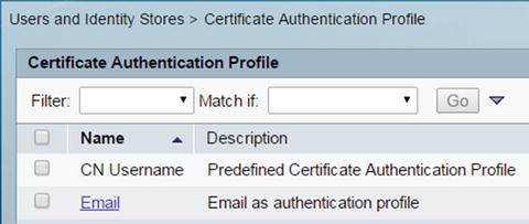
Figure 16-33. Certificate based authentication profile
You can also set a specific way to search various identity stores, in case there are multiple segmented stores. We have defined our lookup method, called User-Search-Order, as shown in Figure 16-34.
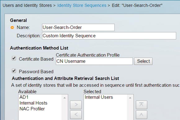
Figure 16-34. Define an identity store lookup order
Next, define the authorization profile, Auth-Lab-Profile, as shown in Figure 16-35.
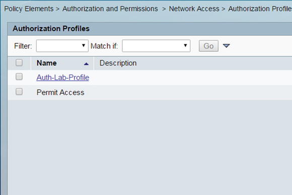
Figure 16-35. Define a new authorization profile
In this authorization profile, we defined a few simple attributes to be downloaded to the switch as dynamic configuration to change the default port VLAN from VLAN 600 (bit bucket) to the corresponding network VLAN 300. These are defined in Figure 16-36.

Figure 16-36. Defining downloadable RADIUS attributes for the client’s port on the switch
Figure 16-37 illustrates a more flexible user interface for defining less common RADIUS attributes to be passed to the AAA Client (NAS). You can also define downloadable access lists (ACL) to the NAS port, as illustrated in Figure 16-38. You can see the name of the downloadable Inbound-ACL, referenced in Figure 16-36.
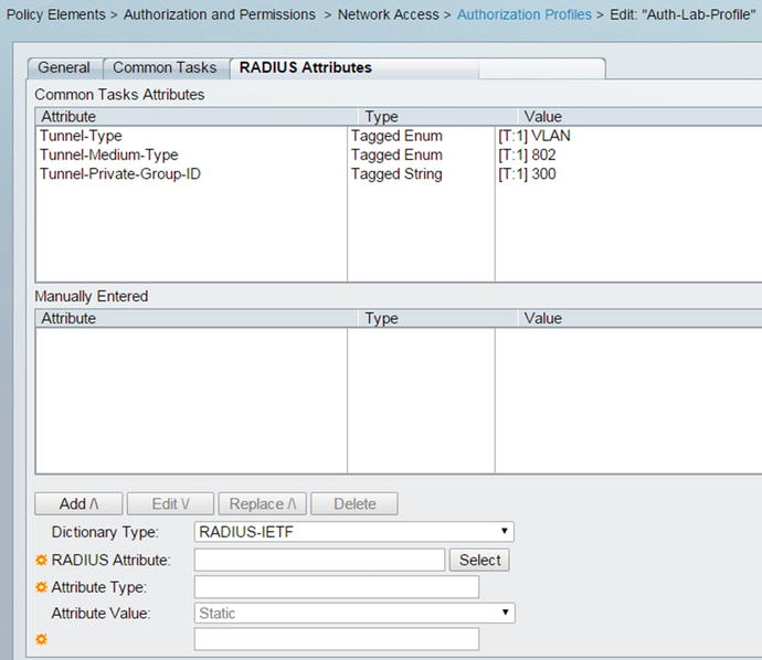
Figure 16-37. View of defined RADIUS attributes for the authorization profile

Figure 16-38. Defining downloadable access lists
Next, attach all defined profiles and policy elements into a Secure-Auth access service, as shown in Figures 16-39 and 16-40.
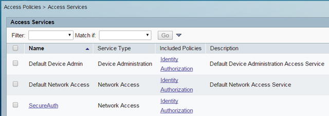
Figure 16-39. Defining access services
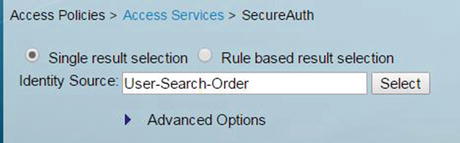
Figure 16-40. Selecting the identify policy for our access service
Figure 16-41 shows the defining of the authorization policy.

Figure 16-41. Defining the authorization policy for the access service
Figure 16-42 shows the custom access service policy.
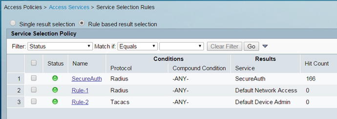
Figure 16-42. The Secure-Auth custom access service policy is active
Now that the RADIUS server is ready is set, we can begin the RADIUS server integration by defining an AAA profile in our AS3 switch. To make testing easier between the NAS/AAA client and the RADIUS service, temporarily define a test profile or allow PAP/ASCII for a predefined test user, as illustrated in Figure 16-43.
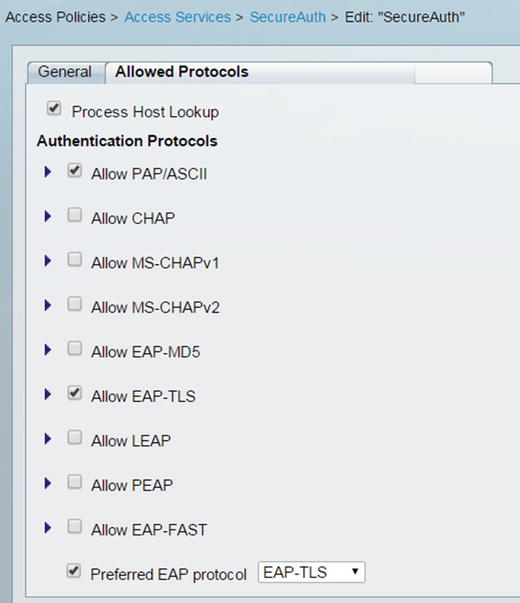
Figure 16-43. Select allowed EAP protocols for authentication
The following are configuration snippets for AS3.
! Defining a 802.1x authentication, authorization and accounting model for
! network access.
aaa new-model
! Use any Radius server in the group for 802.1x
aaa authentication dot1x default group radius
! Allows user profile based access to network resources
aaa authorization network default group radius
! Enables accounting by enabling the watchdog and update packets from
! the supplicant to the Radius server.
aaa accounting dot1x default start-stop group radius
! Track the status of connected devices by sending unicast ARP requests.
! Useful for the purpose of tracking authenticated devices satus.
! Note that device tracking uses ARP inspections and or DHCP snooping to build! a tables of the connected devices.
ip device tracking

!
interface Ethernet3/3
! The port is defaulted to the bit bucket. Via the use of radius attributes
! we will assign it VLAN 300 dynamically.
 switchport access vlan 600

 switchport mode access
 switchport port-security
 ! Place holder for the downloadable ACL
 ip access-group Inbound-ACL in
 duplex auto
! 802.1x commands to enable client authentication
 authentication order dot1x
! Enables authentication on the interface
 authentication port-control auto
 dot1x pae authenticator
 spanning-tree portfast
!

! Radius server configureation
radius-server host 192.168.16.2 auth-port 1812 acct-port 1813 key 1qaz@WSX3edc

! Enable exchange of downloadable Radius attributes
radius-server vsa send accounting
radius-server vsa send authentication
Now let’s test by using the test aaa group radius command, as shown in Figure 16-44. Since we enabled simple PAP/ASCII in the allowed protocols of the access service, this test should work.
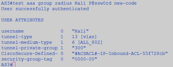
Figure 16-44. Testing RADIUS server and AS3 switch integration
OK now let’s proceed to disable PAP/ASCII, enable only EAP-TLS, and test with a client. First, we set up the clients certificate, which was signed by the CA and select the corresponding user certificate encrypted private key, as shown in Figure 16-45.

Figure 16-45. Linux WPA Supplicant settings for EAP-TLS
Next, let’s discuss the use of OpenSSL to (a) generate certificate request, (b) generate a CA self-signed certificate, and (c) sign certificates with the CA key.
Figure 16-46 shows packet captures for EAP exchanges.

Figure 16-46. Client-based packet capture showing the EAP exchanges culminating in success
The following shows portions of output from enabling “debug dot1x” (see Figure 16-47) and “debug radius authentication” (see Figure 16-48).
![]()
Figure 16-47. Debug dot1x shows authentication success
Figure 16-48 shows the output of the RADIUS authentication debug.
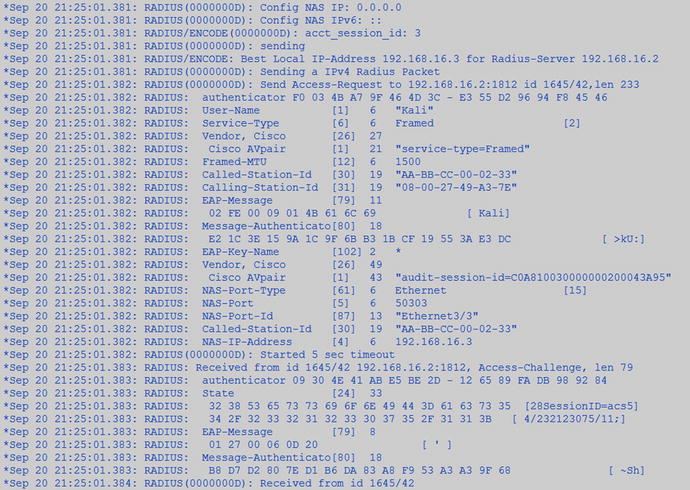
Figure 16-48. Output of debug RADIUS authentication
Examples Using OpenSSL to Generate Signed Certificates
The parameters (arguments) used with each function may vary depending on your needs. This section is meant as general information for those who are not familiar with OpenSSL. We encourage any IT professional to become familiar with the use of OpenSSL and the use of cryptographic algorithms in the IT environment.
- Create the RSA keys:
openssl genrsa –aes56 –out ca.key.pem 4096 - Create the elliptical cryptography key and encrypt the curve parameters:
openssl ecparam –out ca.key.pem –genkey –name secp384r1
openssl ec aes-256-cbc –in ca.key.pem –out ca.encrypted.key.pem - Create a CA self-signed certificate with a default policy:
openssl req –key ca.key.pem –new –x509 –days 366 –sha256 –out ca.cert.pem - Alternatively, use a custom policy file (the following example policy file format):
openssl req –config mypolicy.cnf –new –x509 –days 366 –sha256 –extensions v3_ca –out ca.cert.pem - Create a client certificate request with a default policy:
openssl req –new –key private.key.pem –out client.csr - Create a client certificate request and keys in a single command:
openssl req –new –newkey rsa:4096 -keyout private.key.pem –out cert.csr - Sign the certificate request with the CA certificate:
openssl X509 -req –days 366 –in cert.csr –CA ca.cert.pem -CAkey ca.key.pem –set_serial 01 –out client_cert.signed.pem - Test the integrity of certificates:
openssl x509 –noout –text –in certificate.pem - List the available elliptical cryptography curves:
openssl ecparam –list_curves
A sample structure of a certificate policy configuration file:
#CA policy construct

[ ca ]
default_ca = CA_default

[ CA_default ]
# Directory and file locations.
dir               = /root/ca
certs             = $dir/certs
crl_dir           = $dir/crl
new_certs_dir     = $dir/newcerts
database          = $dir/index.txt
serial            = $dir/serial
RANDFILE          = $dir/private/.rand

# The root key and root certificate.
private_key       = $dir/private/ca.key.pem
certificate       = $dir/certs/ca.cert.pem

# For certificate revocation lists.
crlnumber         = $dir/crlnumber
crl               = $dir/crl/ca.crl.pem
crl_extensions    = crl_ext
default_crl_days  = 31

#Use SHA-2 instead.
default_md        = sha256
name_opt          = ca_default
cert_opt          = ca_default
default_days      = 366
preserve          = no
policy            = policy_strict

[ policy_strict ]
countryName             = match
stateOrProvinceName     = match
organizationName        = match
organizationalUnitName  = optional
commonName              = supplied
emailAddress            = optional

[ req ]
default_bits        = 2048
distinguished_name  = req_distinguished_name
string_mask         = utf8only
default_md          = sha256
x509_extensions     = v3_ca

[ req_distinguished_name ]
countryName                     = Country Name (2 letter code)
stateOrProvinceName             = State or Province Name
localityName                    = Locality Name
0.organizationName              = Organization Name
organizationalUnitName          = Organizational Unit Name
commonName                      = Common Name
emailAddress                    = Email Address

[ v3_ca ]
subjectKeyIdentifier = hash
authorityKeyIdentifier = keyid:always,issuer
basicConstraints = critical, CA:true
keyUsage = critical, digitalSignature, cRLSign, keyCertSign

[ usr_cert ]
basicConstraints = CA:FALSE
nsCertType = client, email
nsComment = "OpenSSL Generated Client Certificate"
subjectKeyIdentifier = hash
authorityKeyIdentifier = keyid,issuer
keyUsage = critical, nonRepudiation, digitalSignature, keyEncipherment
extendedKeyUsage = clientAuth, emailProtection

[ server_cert ]
basicConstraints = CA:FALSE
nsCertType = server
nsComment = "OpenSSL Generated Server Certificate"
subjectKeyIdentifier = hash
authorityKeyIdentifier = keyid,issuer:always
keyUsage = critical, digitalSignature, keyEncipherment
extendedKeyUsage = serverAuth

[ crl_ext ]
authorityKeyIdentifier=keyid:always

[ ocsp ]
basicConstraints = CA:FALSE
subjectKeyIdentifier = hash
authorityKeyIdentifier = keyid,issuer
keyUsage = critical, digitalSignature
extendedKeyUsage = critical, OCSPSigning
CDP and LLDP
Anyone who has used CDP and LLDP knows that these protocols can reveal a great deal of information about network systems. They are very helpful protocols, but also dangerous. Figure 16-49 shows a capture of CDP frames and Figure 16-50 show a capture of LLDP frames.
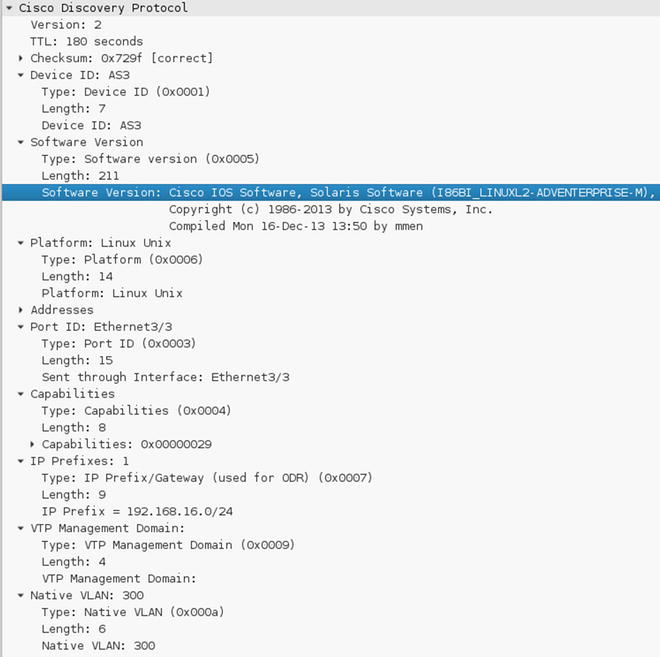
Figure 16-49. CDP capture

Figure 16-50. LLDP capture
As illustrated in Figure 16-50, the information communicated by both protocols is very similar. Of particular use for an attacker is the information about the operating systems version and the IP address that is bound to the device itself—in case an attacker wanted to make targeted attacks. These protocols present a danger from a reconnaissance point of view, as well as their susceptibility to denial-of-service (DoS) attacks. You can mitigate the susceptibility to denial or service attacks by using Control Plane Policing (CoPP) and enabling CDP or LLDP only on trusted and controlled ports. The security recommendation is usually to turn them off, and if needed, use LLDP only. Figure 16-51 illustrates a DoS attack on the CDP protocol using Yersinia.

Figure 16-51. Crafting CDP PDUs from Yersinia
Notice that the MAC spoofing is turned off since the switch is configured with port security. To craft a CDP PDU, press G to select the protocol, press E to enter PDU edit mode, and then press X for the payload. In Figure 16-50, we used the CDP packet crafted in Figure 16-51 to flood the CDP table of the unsecured switch.
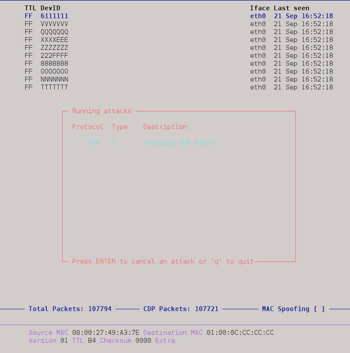
Figure 16-52. CDP table flooding is elected as the attack
Figure 16-53 shows the effects of the CDP attack.
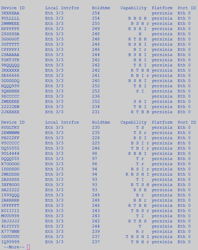
Figure 16-53. Effects of CDP table flooding
The occurrence of a resource-exhaustion attack without Control Plane Policing to provide rate limiting is just a matter of time (see Figure 16-53). Figure 16-54 displays the manufactured CDP entries.
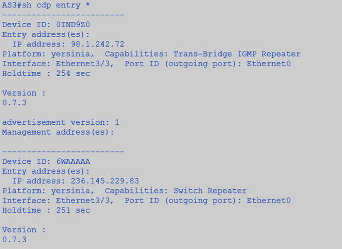
Figure 16-54. CDP phony entries
As a demonstration of one of the preventive methods, we decided to turn off CDP in interfaces facing hosts and to relaunch the attack. We leave you with the assignment of exploring where to disable CDP and LLDP and where to police it.
interface Ethernet3/3
 switchport access vlan 600
 switchport mode access
 switchport port-security
 ip access-group Inbound-ACL in
 duplex auto
 authentication order dot1x
 authentication port-control auto
! Disables CDP in the interface. No CDP input or output PDUs.
no cdp enable
! Disables LLDP output PDUs transmission and reception separetly. Transmitting
! LLDP frames is more a problem in respect to reconnaissance however receiving! LLDP frames when no rate limiting or control plane policing is used and can
! leave the receiving end vulnerable to a DoS.
no lldp transmit
no lldp receive
 spanning-tree portfast
Figure 16-55 displays the results of the attack with LLDP and CDP disabled.
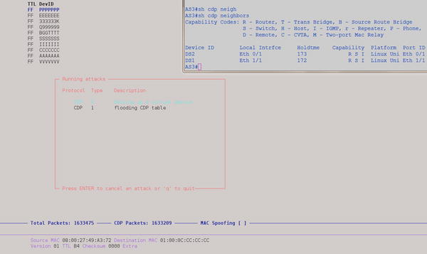
Figure 16-55. With CDP and LLDP disable the DoS attack doesn’t succeed
ARP the Way to IP
The Address Resolution Protocol (ARP) and the Reverse Address Resolution Protocol (RARP) provide the bindings or mappings between layer 2 and layer 3 addressing to enable packet forwarding. The problem with the way the bindings are built is that there is no authentication at layer 2, so it is easy to produce a fake gratuitous ARP message notifying all hosts on the LAN segment that we now have a given IP. The entries in the ARP table will come to reflect it, regardless of whether it is true or not. For example, parting from the configuration that we have built so far with 802.1x and port security, we show that more security is needed by highjacking the traffic meant for server 192.168.16.2 and redirecting the traffic to 192.168.16.3 via a combination of ARP spoofing and IP spoofing. Figure 16-56 displays the MAC address table of DS2.
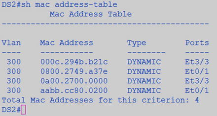
Figure 16-56. MAC address table of DS2
Figure 16-57 shows the MAC address of the target for the attack.
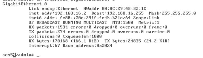
Figure 16-57. MAC address of the targeted server
Figure 16-58 shows the man-in-the-middle (MiTM) attack preparation with Ettercap.
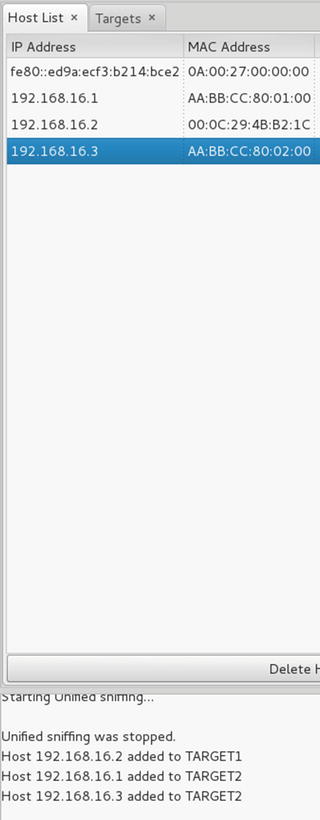
Figure 16-58. Preparing the attack on Ettercap, MiTM ARP Poisoning
Figures 16-59 and 16-60 show the effect that the ARP spoofing attack had on AS3 and DS2.

Figure 16-59. ARP MAC to IP bindings changed during the ARP spoof attack on the access switch

Figure 16-60. ARP MAC to IP bindings changed during the ARP spoof attack on the distribution switch
Since the bindings between MAC addresses and IPs are not static, the table can easily be dynamically spoofed. And since we have a VLAN spanning network, the effects propagated to the distribution switch too. There are two ways to address this problem: (1) using Dynamic ARP inspection (DAI) in conjunction with DHCP snooping for those systems that will use DHCP, and (2) using static ARP entry bindings or IP source bindings for crucial systems like servers that are more static in their network presence.
The following is an ARP Poisoning attack guide.
- Open Ettercap.
- Select Sniff Unified Sniffing.
- Select Hosts Scan for Hosts.
- Select Hosts Hosts List.
- Select IP ARP entry to poison as “Target 1” (In this case 192.168.16.2).
- Select hosts to send gratuitous spoofed ARPs as “Target 2” (any other host on the LAN).
- Select MiTM ARP Poisoning.
- Select Sniff Remote Connections.
- Change the attacker IP to be that of the target as shown in Figure 16-61.
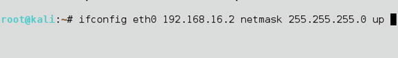
Figure 16-61. Change the attacker’s IP to impersonate the victim
Figure 16-62 displays the ARP table of DS2 after the attack.

Figure 16-62. The MAC address entry in the ARP table entry for the IP 192.168.16.2 now matches the attacker MAC address. ICMP echo requests meant for the original server are sent to the attacker’s host
An easy way to mitigate ARP spoofing is to make static ARP bindings for non-transient resources such as the targeted server, as shown in Figure 16-63. Relaunch the attack with the static bindings present, and the attack fails.
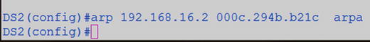
Figure 16-63. Static ARP binding
Another way is to use the ip verify source port-security feature and make an IP source static binding. The IP source binding, unlike static ARP bindings, also includes the VLAN and the interface information for better containment. You can enable the IP verify source in the interface, as follows.
! Deterministic static binding
(config)#ip source binding 0800.2749.A37E vlan 300 192.168.16.200 int ethern 3/3
interface Ethernet3/3
 switchport access vlan 600
 switchport mode access
 switchport port-security
 ip access-group Inbound-ACL in
 duplex auto
 authentication port-control auto
 dot1x pae authenticator
 no cdp enable
 no lldp transmit
 no lldp receive
 spanning-tree portfast
 service-policy output PDU_RESTRICT
! Enables IP source address and MAC address paring verification
 ip verify source port-security
For transient resources, such as hosts that use DHCP, it is better to use DHCP snooping with Dynamic ARP Inspection (DAI) ip arp inspection and the IP Verify feature ip verify source. When you enable dynamic configuration of these features, they are all dependent on the DHCP snooping feature working properly, since the binding database is built based on the original DHCP request and the response to pair the MAC address to the IP address. Figure 16-64 illustrates the relationship between these security features.
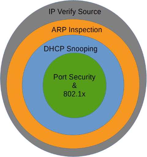
Figure 16-64. Relationship between LAN security features
Figures 16-65, 16-66, 16-67, and 16-68 illustrate what happens when the ARP poisoning attack is relaunched with the IP verify source enabled. The ARP poisoning attacks fail, and the ICMP echo requests (ping) with a spoofed IP address also fails.
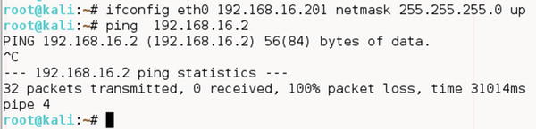
Figure 16-65. The IP address is changed to 192.168.16.201 and sent ICMP echo requests to test
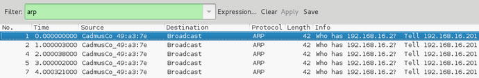
Figure 16-66. With IP verify source, no ARP replies are received for the ARP requests with IP 192.168.16.201
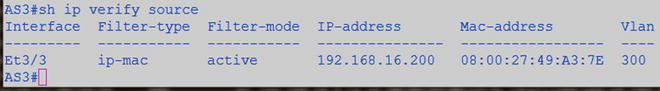
Figure 16-67. Verifying the IP verify source
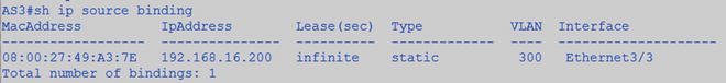
Figure 16-68. Verifying the IP source bindings
Private VLANs are a way to further subdivide VLANs. As you know, VLANs provide a way to separate layer 2 traffic on a switched domain. If you need to have sales and services traffic flow through the same layer 2 device, you can create separate VLANs to isolate the traffic and forward to the VLAN interface or the Switch Virtual Interface (SVI).
Private VLANs work in much the same way; however, they share the same SVI. So instead of needing two VLANs, and two separate networks to split the layer 2 traffic of sales and services, you can use the same SVI, VLAN, and network.
Use Case
Keeping to the sales and services example, it’s important that you to keep their traffic separate; let’s say, for example, because of business regulations. However, you’ve only been provided a small CIDR and you’ve been told you can’t break down that network. To accomplish this, you can use private VLANs. By configuring two community VLANs that reside under the primary VLAN, you are able to use the same SVI, but maintain the layer 2 separation that VLANs provide. Let’s say that in sales, there was a special group that should not have their traffic mixed with anyone else at layer 2. You would make this group isolated, which means that they can’t talk to anyone else but the SVI at layer 2; not even to each other.
Promiscuous vs. Community vs. Isolated
Private VLANs are comprised of three types of ports: promiscuous, community, and isolated.
We haven’t talked about promiscuous ports yet, but they are pretty close in function to their name. They can talk with all interfaces in their associated primary VLAN. This means that they can talk to community and isolated ports at layer 2. A promiscuous port can be associated with one primary VLAN and any number of community and isolated VLANs within the same primary VLAN.
With community ports/VLANs, the devices in the same community can talk to each other at layer 2; however, they cannot talk to any other community or isolated ports/VLANs. They must use the SVI at layer 3 to talk to any other devices.
Isolated VLANs are just like they sound. They cannot talk to any other isolated or community ports/VLANs at layer 2.
Configuration
To configure private VLANs you first need to identify your scheme. For the example, your private VLAN would be your company; so VLAN 5 XYZCompany would be your primary VLAN and you would have two secondary community VLANs: VLAN 10 and VLAN 20—sales and services, respectively.
![]() Note If you are using VTP 1 or 2, private VLANs are not supported, so you have to manually create the VLANs in each switch, as if you were not using VTP at all. VTP version 3 does support private VLANs.
Note If you are using VTP 1 or 2, private VLANs are not supported, so you have to manually create the VLANs in each switch, as if you were not using VTP at all. VTP version 3 does support private VLANs.
To configure the primary VLAN, ensure that VTP is configured as transparent. Once in configuration mode, enter the following commands:
Router(config)# Vlan 5
Router(config-vlan)# Private-vlan primary
Router(config-vlan)# Name XYZCompany

Router(config-vlan)# Vlan 10
Router(config-vlan)# private-vlan community
Router(config-vlan)# name Sales
Router(config-vlan)# Vlan 20
Router(config-vlan)# private-vlan community
Router(config-vlan)# name Services
As you can see from this example, it is not necessary to back out completely to make the new VLANs.
Now that all of the private VLANs have been created for the scenario, let’s associate them with the primary VLAN. To do this, you use the association command, and include the community and isolated VLANs. Here there are only two community VLANs:
Router(config-vlan)# vlan 5
Router(config-vlan)# private-vlan association 10, 20
Router(config-vlan)# end
In order to take advantage of the layer 3 function of private VLAN, you have to associate the secondary VLANs with the primary VLAN Interface. That configuration for the example is as follows:
Router(config-vlan)# interface VLAN 5
Router(config-if)# Private-vlan mapping add 10,20
Router(config-if)# end
To configure an access port as a PVLAN port, you do the following:
Router(config-if)# interface e1/1
Router(config-if)# switchport mode private-vlan {host | promiscuous}
Router(config-if)# switchport private-vlan host-association 5 10
Router(config-if)# end
Router(config)#
If you were to step out the command for the switchport private-vlan host-association, here’s what you would see:
Switch(config-if)#switchport private-vlan host-association ?
  <1006-4094>  Primary extended range VLAN ID of the private VLAN host port association
  <2-1001>     Primary normal range VLAN ID of the private VLAN port association

Switch(config-if)#switchport private-vlan host-association 5 ?
  <1006-4094> Secondary extended range VLAN ID of the private VLAN host port association
  <2-1001>     Secondary normal range VLAN ID of the private VLAN host port association

Switch(config-if)#switchport private-vlan host-association 5 10 ?
  <cr>
The following configuration adds a promiscuous port:
Router(config-if)# interface e1/2
Router(config-if)# switchport mode private-vlan promiscuous
Router(config-if)# switchport private-vlan mapping 5 10,20
Router(config-if)# end
Extending Across L2 Trunk
You must make sure that you extend the private-vlan and configuration across any switch that you wish to participate in the private-vlan configuration. That being said, there is no further configuration to ensure functionality across a layer 2 trunk, other than making sure that the associated VLANs traverse the trunk (e.g., in the switchport trunk–allowed VLANs list, in a forwarding and not pruned state.)
Extending Across Access Port
If you connect a switch to another switch using a private-vlan port, that configuration continues to the next switch.
Incorporating in a non-PVLAN Capable Switch
If you configure an access port as a community port, then the switchport and all associated ports (think ports in the same VLAN) will carry the treatment forward into the configured domain.
Using Extended ACLs, PACL, and VACL
In the next section, let’s talk about the use case and configuration of extended ACLs, port ACLs, and VLAN ACLs.
Extended ACL
This section covers the configurations of Extended ACLs.
Use Case
Extended Access Control Lists (ACLs) are used for many different purposes—from filtering, to tracking, to policing. They are used on interfaces inbound and outbound. They are used in route maps, leak maps, and suppress maps. They are used in class maps for both regular and inspect (firewalling) policy maps (regular and inspect). They can even be used for multicast.
Configuration
There are a large number of options available for configuring extended ACLs; you could write a whole book about them. Here, let’s walk through configuring a couple of ACLs that you would normally see in a production environment, and possibly a couple that you should never see. Then you’ll practice designing a few, just to get you warmed up.
It’s important that you understand which direction the ACLs are being applied, because if you design an ACL for inbound and apply it outbound, the function will be different and the results won’t be as you expect. It’s easy to get turned around when working with directional ACLs. One of the most important things you can remember is this: inbound affects the traffic flowing into an interface, outbound ACLs filter traffic flowing through the device (e.g., from an external device that’s sending traffic through the interface you are applying the ACL to). This is important because if you attempt to set an outbound filter on an interface, and then try to test it using an interface/address on the same device, you might think the filter isn’t working.
As you saw earlier, the extended ACL is commonly configured as follows:
Action ![]() protocol
protocol ![]() source
source ![]() destination
destination ![]() functions
functions
The syntax command for an extended ACL is: access-list access-list-number {permit | deny} protocol source source-wildcard [operator port] destination destination-wildcard [operator port] [established] [log]
Let’s ignore the action, protocol, and functions for now and talk about directionality. We want to look at a conversation between 1.1.1.1 and 2.2.2.2. Interface G0/0 on router 1.1.1.1 is connected through another router to G1/0 on router 2.2.2.2:
Let’s look at an extended ACL scenario, using Figure 16-69.

Figure 16-69. Extended ACL diagram
Looking at interface G0/0 on router 1.1.1.1, if you apply an inbound ACL to affect inbound traffic from 2.2.2.2 to 1.1.1.1, the line will look like this:
Permit host 2.2.2.2 host 1.1.1.1
Or
Deny host 2.2.2.2 host 1.1.1.1
If you were to take that line and apply it outbound, this would not work, as it would be looking for a source (2.2.2.2) on router 1.1.1.1 going through to its destination (1.1.1.1) on router 2.2.2.2 (e.g., you wouldn’t be able to ping from R1). This means that in this scenario, your ping would succeed.
So while the field name doesn’t change, it’s important to understand the perspective of the application of the ACL when you are applying it to correctly predict the results.
VACL
This section covers the configuration of VACLs.
Use Case
VLAN Access Control Lists (VACLs) are primarily used to filter traffic at layer 2 within a VLAN. They can be used to filter external traffic as well; however, this is more efficiently accomplished with layer 3 ACLs.
The scenario is that you have several servers from different companies housed in your data center. You have a single VLAN providing L2 and L3 connectivity for these types of servers; however, you have a requirement to provide L2 protection from each other. Without using private VLANs, configure the network to provide this protection.
Configuration
First, you need to configure your filters. You can use MAC or IP access-lists within your VACL. Here you’ll use a MAC access-list to filter out source destination MAC addresses from being able to talk to each other.
mac access-list extended BLOCK_SERVERS
 deny   host 0000.0000.0001 host 0000.0000.0002
Then you need to build the access-map to drop the selected traffic and permit any further traffic.
Switch(config)#vlan access-map VLAN_3_FILTER 10
Switch(config-access-map)#match mac add BLOCK_SERVERS
Switch(config-access-map)#action drop
Switch(config-access-map)#vlan access-map VLAN_3_FILTER 20
Then you need to apply the access-map to the VLAN.
Switch(config)#vlan filter VLAN_3_FILTER vlan-list 3
The next few commands help validate that the map is built and applied.
Switch#sh access-list BLOCK_SERVERS

Extended MAC access list BLOCK_SERVERS
    deny   host 0000.0000.0001 host 0000.0000.0002
Switch#sh vlan access-map
Vlan access-map "VLAN_3_FILTER"  10
  Match clauses:
    mac address: BLOCK_SERVERS
  Action:
    drop
Vlan access-map "VLAN_3_FILTER"  20
  Match clauses:
  Action:
    forward
Switch#sh vlan filter
VLAN Map VLAN_3_FILTER is filtering VLANs:
  3
PACL
This section covers the configuration of PACLs.
Use Case
The Port Access Control List (PACL) is a standard, extended or MAC ACL applied to a layer 2 interface. This allows you to filter L3 and L4 transit traffic in and out of a port. This could be used to deny ICMP traffic to a specific client on a switchport, or to protect a web server sitting on an access port. One important thing to remember is that PACLs are only applied inbound and are handled in hardware, so it’s not going to be able to be simulated.
Configuration
Let’s look at a scenario, similar to the extended ACL scenario, using Figure 16-70.

Figure 16-70. PACL diagram
In this instance, let’s apply the ACL on the access port that you’re going to use to connect R1 and R2 together. These two ports will be switchport access and the VLAN doesn’t really matter for this, as long as they are the same on each end.
On the switch, configure external ACL as follows:
Ip access-list extended BLOCK_ICMP_PACL
     Deny icmp host 1.1.1.1 host 2.2.2.2
     Permit ip any any
On the port connecting to router 1 (port E0/1 on S1), apply the ACL to the switchport.
Now when you ping from R1 using the loopback, to R2’s loopback, the packet is going to be filtered on the switchport.
You can also do this using SVIs between two switches to validate your knowledge. Connect using access ports between Sw1 and Sw2, and create addresses in the same subnet on each switch. Use the PACL to filter ICMP from one switch to the other. Make sure that you do the permit ip afterward, and then on the opposite switch that you’re filtering, create a simple http ip sla. You should not be able to ping from one direction to the other with the PACL in place, but your IP SLA should increment the successes.
Troubleshooting
Troubleshooting is much like it is with extended ACLs. If it’s not working, however, your best bet is to rebuild the list. Because this is used in hardware, you are not going to see counters increment on the PACL as you would with regular ACLs.
AAA
The follow sections discuss AAA use case and configuration.
Use Case
Authentication, authorization, and accounting (AAA) is used in many different situations for many different functions. It is generally used for access and accounting of a network device. However, it is often used for CHAP, 802.1x, and other types of protocols requiring AAA services.
Console
Using a separate method list, you can have the console authenticate locally and still use a TACACS or a RADIUS server for accounting. It is important to have some sort of AAA on your console port, as this is the last line of defense from compromising your network devices. There’s an old saying that if I have to worry about someone compromising my device via the console port, then I have bigger issues. This is partially true: as you know, if you have physical access to a device, that’s half the battle. That being said, a little extra security will benefit and keep most people from looking at or possibly causing damage to your network.
Most people don’t lock this port down because it’s traditionally used for remote access via modem or some other type of Out of Band (OOB) management. When you are in the middle of troubleshooting, it’s easy to forget that the AUX port is a viable console port and it has the same access as the console port in most cases.
VTY Ports
These are the ports used to access the devices remotely. It’s important to have AAA configured on these ports. These can be configured with different method lists and different transport protocols to allow multiple access methods.
Local Authentication and Authorization
It is possible to configure user credentials on your devices. And most of the time, even if you are using external AAA (TACACS or RADIUS), you will probably still have at least one local account on your device. If you suddenly are unable to authenticate using your TACACS or RADIUS server, you might need access to the device. This is why it’s a good rule of thumb to have an emergency account on the devices themselves. One thing to ensure, though, is that these accounts aren’t in the TACACS or RADIUS servers, as that would defeat the purpose of AAA.
Remote AAA (TACACS, RADIUS)
Most remote AAA is handled by TACACS for network devices. This is because even though it’s a Cisco proprietary solution, it’s well documented and relatively easy to configure. And as Cisco is primarily a networking company, the AAA solution that the Access Control Server (ACS) provides is well suited to network devices.
RADIUS is a protocol used mostly for servers. It is supported by the ACS server and is configurable as a server in the TACACS configuration on network devices.
Configuration
You first need to think about your scheme. Are you going to do a simple configuration where you use the default method list, and only define what you want to authenticate, authorize, and account for? Do you want to have multiple method lists? Let’s say, one for VTY, one for console, and one for AUX.
Are you going to have multiple ACS servers or multiple locations? These drive the architecture that you use for TACACS configuration of AAA.
First, configure a username on your device. We’ll assume you already know how to do that at this point, but if you don’t, here’s a simple example:
Router(config)#username cisco privilege 15 password cisco
Router(config)#aaa new-model
Router(config)#
After configuring your username and enabling AAA, it’s always a good idea to go ahead and log in to the device using this new username. In the following, you see what it looks like when you are not logged in (default in enable mode, and then what it looks like once you log in with your username).
R1#who
       Line       User       Host(s)           Idle              Location
*  0 con 0                    idle                 00:00:00

  Interface    User               Mode         Idle     Peer Address
R1(config)#do login

User Access Verification

Username: cisco
Password:

R1(config)#do who
        Line       User       Host(s)          Idle             Location
*  0 con 0     cisco      idle                 00:00:00

  Interface    User               Mode         Idle     Peer Address
As you can see, once you are logged in, using the who command displays information about the usernames of the individuals that are logged in to the device. The star indicates the line that you are logged in with. Line shows you how the user is connecting, either via console, VTY, or modem. The user shows you who is logged in, whether it is a local account or a TACACS or RADIUS account. Idle shows you how long the user has been idle. Users can get stuck as logged in, even though they may not actually be, tying up lines. Location, if coming on VTY, displays the IP address that the user is connecting from. This is important information to know when you have multiple users logged into the same device (e.g., if you want to send a message to a particular line, or disconnect a particular line, but you did not want to disconnect yourself).
Look at the following to configure AAA, which is the simplest configuration that you can do without a TACACS or a RADIUS server.
R1(config)#aaa authentication login default local
R1(config)#aaa authorization command 15 local
R1(config)#aaa authorization exec local
Notice that there are no accounting statements. Without an ACS server, accounting will not be logged. The only option for accounting is TACACS. Looking through the configuration, and actually doing configuration, it seems that you could define a RADIUS server group, and reference that group in the AAA accounting statement; however, it does not take the command. It proceeds forward as if it did, however, when you look at the config, it does not take. You can see this even when you use group tacacs+ group <server_list>—it looks as if it takes the command, but it doesn’t.
Router(config)#aaa accounting commands 15 default start-stop group tacacs+ group TEST_THIS
Router(config)#do sh run
##### omitted for brevity ######
!
aaa new-model
!
!
aaa group server tacacs+ ENT-AAA
!
aaa group server radius TEST_THIS
 server 1.1.1.1 auth-port 15 acct-port 16
!
aaa authentication login default local
aaa authentication login ENT-AAA local
aaa authorization console
aaa authorization exec default local
aaa authorization exec ENT-AAA local
aaa authorization commands 15 default local
aaa authorization commands 15 ENT-AAA local
!
!
!

Router(config)#aaa accounting commands 15 default start-stop group tacacs+
Router(config)#do sh run
!
aaa new-model
!
!
aaa group server tacacs+ ENT-AAA
!
aaa group server radius TEST_THIS
 server 1.1.1.1 auth-port 15 acct-port 16
!
aaa authentication login default local
aaa authentication login ENT-AAA local
aaa authorization console
aaa authorization exec default local
aaa authorization exec ENT-AAA local
aaa authorization commands 15 default local
aaa authorization commands 15 ENT-AAA local
aaa accounting commands 15 default start-stop group tacacs+
!
!
If you have a TACACS server, you can use group tacacs+ in your statements, as well as accounting.
Start by configuring the tacacs-server statement in the device.
Router(config)#tacacs-server host 1.1.1.1
Router(config)#tacacs-server key cisco
If you are running newer code, you can combine this command as follows:
Router(config)#tacacs-server host 1.1.1.1 key cisco
Cisco is currently working to degrade the CLI for the legacy configurations of configuring TACACS, and it is moving toward exclusively using server lists for TACACS server assignment. We have previously mentioned TACACS method lists, but let’s get a little more specific. A method list allows you to configure methods of AAA by configuring lists that contain specific AAA statements. You can use server lists, TACACS+ or RADIUS, in each of your AAA statements. Server lists can be either TACACS or RADIUS.
To configure a TACACS server list, use the following commands:
Router(config)#aaa group server tacacs+ GROUP_NAME
Router(config-sg-tacacs+)#server-private 1.1.1.1 key cisco
If you plan of using the server list, you use the name when defining the AAA statements.
Router(config)#aaa authentication login VTY_METHOD_LIST group TACACS_SERVER_LIST local
What we are doing here is assigning the method list VTY_METHOD_LIST, the TACACS+ server group TACACS_SERVER_LIST, and if it can’t do anything with the defined servers in the list, it’ll use the local user database for authentication. You can use the local database for authentication and authorization, but not for accounting.
These lists can be used to apply different requirements to different “interfaces” for AAA. For example, you can have a CONSOLE method list that only authenticates locally, and you can have a VTY method list that requires authentication, authorization, and applies accounting. The following are a couple of examples.
Switch(config)#aaa authentication login CONSOLE local
Switch(config)#line con 0
Switch(config-line)#login authentication CONSOLE
Here is the debugging of the authentication on the console port using the CONSOLE method list with local authentication.
User Access Verification

*Apr 30 16:46:40.003: AAA/LOCAL: exec
*Apr 30 16:46:40.007: AAA/BIND(00000008): Bind i/f
*Apr 30 16:46:40.011: AAA/LOCAL: new_ascii_login: tty 6613B37C idb 0
*Apr 30 16:46:40.011: AAA/AUTHEN/LOGIN (00000008): Pick method list 'CONSOLE'
*Apr 30 16:46:40.015: AAA/LOCAL/LOGIN(00000008): get user
Username: cisco
Password:

R1#
*Apr 30 16:46:44.387: AAA/LOCAL/LOGIN(00000008): get password
*Apr 30 16:46:45.315: AAA/LOCAL/LOGIN(00000008): check username/password
Now add authorization to the method list, and here is the debug. The new configuration is as follows:
R1#sh run | inc aaa|tacacs|server
aaa new-model
aaa authentication login CONSOLE local
aaa authorization console
aaa authorization exec CONSOLE local
aaa authorization commands 15 CONSOLE local
aaa session-id common
no ip http server
no ip http secure-server
tacacs-server host 1.1.1.1 key cisco
tacacs-server key cisco
It’s important to note that in the preceding configuration, there is an added statement: aaa authorization console. Without this command, the application of these statements to the line Con 0 will be useless, and the console message tells you so.
Router(config-line)#authorization comm 15 TEST_THIS
%Authorization without the global command 'aaa authorization console' is useless
Also with the key at the end of the tacacs-server host statement, the tacacs-server key alone is not required.
And now the debug...
User Access Verification

Username:
*Apr 30 16:56:03.271: AAA/LOCAL: exec
*Apr 30 16:56:03.275: AAA/BIND(0000000A): Bind i/f
*Apr 30 16:56:03.279: AAA/LOCAL: new_ascii_login: tty 6613B37C idb 0
*Apr 30 16:56:03.279: AAA/AUTHEN/LOGIN (0000000A): Pick method list 'CONSOLE'
*Apr 30 16:56:03.283: AAA/LOCAL/LOGIN(0000000A): get user
Username: cisco
Password:
*Apr 30 16:56:09.247: AAA/LOCAL/LOGIN(0000000A): get password

R1#
*Apr 30 16:56:17.971: AAA/LOCAL/LOGIN(0000000A): check username/password
*Apr 30 16:56:17.975: AAA/AUTHOR (0xA): Pick method list 'CONSOLE'
*Apr 30 16:56:17.979: AAA/LOCAL/AUTHEN: starting
*Apr 30 16:56:17.987: AAA/AUTHOR/EXEC(0000000A): processing AV cmd=
*Apr 30 16:56:17.987: AAA/AUTHOR/EXEC(0000000A): processing AV priv-lvl=15
*Apr 30 16:56:17.987: AAA/AUTHOR/EXEC(0000000A): Authorization successful
Just to show you what’s going on in the background, here’s the debug from the show run | inc aaa|tacacs|server command.
R1#
*Apr 30 16:58:10.935: AAA: parse name=tty0 idb type=-1 tty=-1
*Apr 30 16:58:10.935: AAA: name=tty0 flags=0x11 type=4 shelf=0 slot=0 adapter=0 port=0 channel=0
*Apr 30 16:58:10.935: AAA/MEMORY: create_user (0x669B26A4) user='cisco' ruser='R1' ds0=0 port='tty0' rem_addr='async' authen_type=ASCII service=NONE priv=15 initial_task_id='0', vrf= (id=0)
*Apr 30 16:58:10.939: tty0 AAA/AUTHOR/CMD(654404666): Port='tty0' list='CONSOLE' service=CMD
*Apr 30 16:58:10.939: AAA/AUTHOR/CMD: tty0(654404666) user='cisco'
*Apr 30 16:58:10.939: tty0 AAA/AUTHOR/CMD(654404666): send AV service=shell
*Apr 30 16:58:10.939: tty0 AAA/AUTHOR/CMD(654404666): send AV cmd=show
R1#
*Apr 30 16:58:10.939: tty0 AAA/AUTHOR/CMD(654404666): send AV cmd-arg=running-config
*Apr 30 16:58:10.943: tty0 AAA/AUTHOR/CMD(654404666): send AV cmd-arg=<cr>
*Apr 30 16:58:10.943: tty0 AAA/AUTHOR/CMD(654404666): found list "CONSOLE"
*Apr 30 16:58:10.943: tty0 AAA/AUTHOR/CMD(654404666): Method=LOCAL
*Apr 30 16:58:10.943: AAA/AUTHOR (654404666): Post authorization status = PASS_ADD
*Apr 30 16:58:10.943: AAA/MEMORY: free_user (0x669B26A4) user='cisco' ruser='R1' port='tty0' rem_addr='async' authen_type=ASCII service=NONE priv=15 vrf= (id=0)
Another useful command is config-command. This command authorizes every command that is not normally authorized. Think about it like this: when you are configuring authorization with your AAA statement, you are defining what level of commands you wish to be authorized. This means that if you only have command 15, then it’s only going to authorize the level 15 commands with the TACACS server. If you want level 10 commands to be authorized, you need to have a command 10 statement as well.
This is important because if you start using command sets on the ACS server, the commands you define might be in level 0, 10, and 15. If you don’t authorize these commands with the config-command, and add the appropriate command <level> statement, your command sets might function counter to your expectations, or they might not work at all. We will not go over the command set configuration in the ACS server in this book; however, if you are an ACS administrator, this is a valuable tool to create specific sets of commands for users that might need some higher-level commands, but don’t need all of them.
The full command is as follows:
Router(config)#aaa authorization config-commands
Here’s a complete configuration that will support authentication, authorization, accounting and the use of command sets from the ACS server.
aaa new-model
!
!
aaa group server tacacs+ SERVER_LIST
 server 1.1.1.1
 server-private 1.1.1.1 key cisco
 ip tacacs source-interface Loopback0
!
aaa authentication login TEST_THIS group SERVER_LIST local
aaa authorization console
aaa authorization config-commands
aaa authorization exec TEST_THIS group SERVER_LIST local
aaa authorization commands 0 TEST_THIS group SERVER_LIST local
aaa authorization commands 10 TEST_THIS group SERVER_LIST local
aaa authorization commands 15 TEST_THIS group SERVER_LIST local
aaa accounting exec TEST_THIS start-stop group SERVER_LIST
aaa accounting commands 0 TEST_THIS start-stop group SERVER_LIST
aaa accounting commands 10 TEST_THIS start-stop group SERVER_LIST
aaa accounting commands 15 TEST_THIS start-stop group SERVER_LIST
aaa accounting connection TEST_THIS start-stop group SERVER_LIST
If you’ve configured AAA before and used the aaa authentication enable command, you’ll notice that here we are not using it. This is because that command only works with the default method list since we are defining our own method list, we are not using that command. That command adds another layer of authentication that you might deem necessary. When using the default method list, if you add the enable command, it will check with the configured “method” and whether you have authenticated the request of another password. If you have configured a separate enable password on the account (most of the time you won’t), then you enter that password then. If you didn’t configure a separate password, then you put your primary password in again, and if the TACACS server isn’t available, it will require the local enable password.
Another command that really doesn’t require much coverage is the command aaa accounting connection TEST_THIS start-stop group SERVER_LIST. It basically keeps the ACS server updated with who’s logged into a device. Remember that the ACS server doesn’t actively track who is on which device, or what they are doing; it handles authentication and authorization requests when they come, and accounting is sent to the ACS server, but it doesn’t keep a running tab of who’s currently logged in to what device. This command meets that requirement.
The last thing we need to go over for configuration is what to put on the actual lines. This is relatively simple, and for the most part, it is the same across the lines.
authorization commands 0 TEST_THIS
authorization commands 10 TEST_THIS
authorization commands 15 TEST_THIS
authorization exec TEST_THIS
accounting commands 0 TEST_THIS
accounting commands 10 TEST_THIS
accounting commands 15 TEST_THIS
accounting connection TEST_THIS
accounting exec TEST_THIS
login authentication TEST_THIS
These commands are used for Line Con 0, VTY 0 15, and AUX port configurations.
We have gone over a lot of commands that will make configuration of AAA on devices when using either the local database or the external server function properly, but there is one last thing to consider, and this is more of an architectural vs. functionality issue. When a device is configured in the ACS server, you can define a single IP, a number of IPs, or a range of IPs for the device to use for AAA. If your ACS administrator wants to configure every IP address that is on every device, then there is nothing further to configure on your device. However, if your ACS administrator only wants one IP per device, usually you have a loopback on routers/layer 3 (L3) devices, and a management address on layer 2 (L2) devices. For the L2 devices, you also don’t need to do anything else, as they will only use the active address, and won’t use more than one for AAA.
Layer 3 devices and routers, however, use whichever address is the egress path to the ACS server; so depending on which links are up, and how many links you have per device, this could be any number of addresses. AAA provides a method to solve this. The command is configured either in the global or in the server lists, and sometimes must be configured in both places. The configuration is the same for both methods, but depending on your version of code, it may not be configurable in the server list. The command is IP tacacs source-interface <interface>.
When you configure this command, the device always uses that interface to perform AAA. This is why we usually use a loopback on a routed or L3 device.
AAA must be configured in a particular order of operation (e.g., what do you put in when, and how do you keep from locking yourself out of the device). If you are going to configure AAA on a production device, it’s important to follow a certain order when applying the method list to the VTY or console. If you put them in the wrong order, you can actually create a situation where you are no longer authorized to enter the commands to finish applying the AAA statements. This puts you in a bad spot because you have to reload the device to gain management access again, and if that’s a high-priority device, you might not get the opportunity.
When applying to the VTY or console, use the following order:
- Log in to the device using the local authentication.
- Enter the AAA statements in the global configuration mode (if you’re using the default method list, remember that the default is active immediately. Once you enter the global AAA statement, it immediately takes effect.
- Move into the CONSOLE or VTY.
- Enter the login authentication <METHOD LIST>.
- Enter the authorization command 15 <METHOD LIST>.
- Enter the authorization exec <METHOD LIST>.
One way to ensure that you can still get back in is to configure some lines and not the others. A lot of times, people configure VTY 0–15. This configures all lines the same, and most of the time it is more efficient. However, if you configure VTY 0–4 and VTY 5–15, and you make a mistake on 0–4, you can open five sessions to the device, and your sixth session will use the old validated method. Then you can add the last statement to the 0–4, log in, validate authorization, and then configure 5–15.
Most of the time, you won’t lock yourself out from authentication; it’s authorization that you mess up. When this happens, you have two options.
If you have access to both the device and the ACS server, you can simply take the device out of the ACS server (or change the IP in the server) and you will be able to fix things using the local user account.
If that is not an option, you are left with a reload.
![]() Notes As mentioned previously, the CLI for the TACACS server is being depreciated. That means that Cisco wants to remove these commands from their CLI and move to using server lists permanently. This being said, there are a couple things to note, and there are too many versions, major and minor, for us to go over in this book. However, know this: if you are using the server <SERVER_IP> statement in the server list, you still need to define the tacacs-server host statement in the global config. You will also have to configure the tacacs-server key <key>. This is also true for the ip tacacs source-interface command.
Notes As mentioned previously, the CLI for the TACACS server is being depreciated. That means that Cisco wants to remove these commands from their CLI and move to using server lists permanently. This being said, there are a couple things to note, and there are too many versions, major and minor, for us to go over in this book. However, know this: if you are using the server <SERVER_IP> statement in the server list, you still need to define the tacacs-server host statement in the global config. You will also have to configure the tacacs-server key <key>. This is also true for the ip tacacs source-interface command.
If you are using the server-private <server> key <key> in the server list, you may or may not have to define the tacacs-server host and the tacacs-server key. If you are testing your configuration and it’s not working properly, or tells you there are no TACACS servers defined, this is what they are talking about.
Advanced Security Exercises
This section provides exercises to reinforce what was covered this chapter.
Exercise 1: Extended ACL Exercises
- Create an ACL that permits ICMP HTTP, but denies HTTPS/LDAP and all UDP from network 192.168.0.0/24 to 192.168.1.0/24.
- Create an ACL that logs the input of all TCP packets that come from the host 192.168.1.4 going to the host 192.168.6.2.
- Create an ACL to support a suppress map that will not suppress the addresses 192.168.1.0/24, 192.168.2.0/24, and 192.168.3.0/24, and allows all other networks to be suppressed in the aggregate-address 192.168.0.0 255.255.0.0.
- Create an ACL to support a route map for policy routing to match all packets from 192.168.0.0/24 to any address.
Exercise 2: AAA Exercises
Create a method list using the TACACS+ server group XYZCompany, whose ACS servers are 192.168.1.1, 192.168.5.1, and 192.168.10.1.
- The TACACS key for these servers is cisco.
- You must configure authorization for exec and command authorization for level 5 and level 15.
- Ensure that all of the preceding can use the server list, as well as local authentication, but make sure that the local is case sensitive.
- Ensure that accounting is configured for all authorization types as well as connection.
- Make sure to configure AAA for the console as well as the VTY ports.
- Do not user the tacacs-server commands and use a single line per server in the server list.
Exercise Answers
This section provides answers to the preceding exercises.
Exercise 1
- Create an ACL that permits ICMP HTTP, but denies HTTPS/LDAP and all UDP from network 192.168.0.0/24 to 192.168.1.0/24
Ip access-list extended FILTER_IN
    Permit tcp 192.168.1.0 0.0.0.255 eq www 192.168.0.0 0.0.0.255
Permit icmp 192.168.1.0 0.0.0.255 echo-reply 192.168.0.0 0.0.0.255 - Create an ACL that logs the input of all TCP packets that come from the host 192.168.1.4 going to the host 192.168.6.2.
Ip access-list extended FILTER_IN
Permit tcp host 192.168.1.4 host 192.168.6.2 log-input - Create an ACL to support a suppress map that will not suppress addresses 192.168.1.0/24, 192.168.2.0/24, and 192.168.3.0/24 and allows all other networks to be suppressed in the aggregate-address 192.168.0.0 255.255.0.0.
IP access-list standard SUPPRESS_MAP
    Permit 192.168.1.0 0.0.0.255
    Permit 192.168.2.0 0.0.0.255
Permit 192.168.3.0 0.0.0.255 - Create an ACL to support a route map for policy routing to match all packets from 192.168.0.0/24 to any address.
Ip access-list extended POLICY_ROUTE
    Permit ip 192.168.0.0 0.0.0.255 any
Exercise 2
aaa new-model
!
aaa group server tacacs+ XYZCompany_Tacacs+
 server-private 192.168.1.1 key cisco
 server-private 192.168.5.1 key cisco
 server-private 192.168.10.1 key cisco
aaa authentication login XYZCompany group XYZCompany_Tacacs+ local-case
aaa authorization exec XYZCompany group XYZCompany_Tacacs+ local
aaa authorization console
aaa authorization commands 5 XYZCompany group XYZCompany_Tacacs+ local
aaa authorization commands 15 XYZCompany group XYZCompany_Tacacs+ local
aaa accounting exec XYZCompany start-stop group XYZCompany_Tacacs+
aaa accounting commands 5 XYZCompany start-stop group XYZCompany_Tacacs+
aaa accounting commands 15 XYZCompany start-stop group XYZCompany_Tacacs+
aaa accounting connection XYZCompany start-stop group XYZCompany_Tacacs+
!
line con 0
 authorization commands 5 XYZCompany
 authorization commands 15 XYZCompany
 authorization exec XYZCompany
 accounting connection XYZCompany
 accounting commands 5 XYZCompany
 accounting commands 15 XYZCompany
 accounting exec XYZCompany
 login authentication XYZCompany
line vty 0 4
 authorization commands 5 XYZCompany
 authorization commands 15 XYZCompany
 authorization exec XYZCompany
 accounting connection XYZCompany
 accounting commands 5 XYZCompany
 accounting commands 15 XYZCompany
 accounting exec XYZCompany
 login authentication XYZCompany
line vty 5 15
 authorization commands 5 XYZCompany
 authorization commands 15 XYZCompany
 authorization exec XYZCompany
 accounting connection XYZCompany
 accounting commands 5 XYZCompany
 accounting commands 15 XYZCompany
 accounting exec XYZCompany
 login authentication XYZCompany
Summary
You have really only scratched the surface of configurations for ACLs VACLs, and PACLs; however, in that brief coverage, you have seen the importance of planning your intent and how to plan to implement, as this can affect the functionality of the ACLs.
AAA is an important part of security. Using it appropriately can provide a wealth of information. And in the event of a mistake, it can show what should be done to help recover from that mistake. Just as with ACLs, however, proper configuration and implementation are paramount to using AAA as an effective resource.
________________
1Official ISC2 Guide to the CISSP, by Harold F. Tipton (CRC Press, 2009).
2John Tiso (Cisco Press, 2011).
3Karl Solie (Cisco Press, 2001).