![]()
Intermediate LAN Switching
This chapter starts with an introduction to Cisco IOS software, discussing some basic configuration commands and how to access a Cisco device. Switching concepts are covered in this chapter, including EtherChannels and the Spanning Tree Protocol. You’ll also take a look at the IOS, including configurations and the file system.
To access a Cisco device, you need to use a console cable and connect it to the console port on the router of a computer with a terminal emulator. Your computer needs to be configured as follows (also see Figure 5-1):
- Speed (baud rate): 9600
- Parity: None
- Data bits: 8
- Stop bits: 1
- Flow control: XON/XOFF
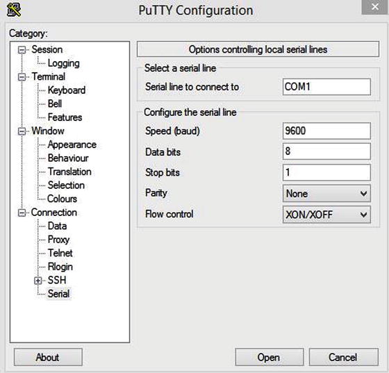
Figure 5-1. PuTTY configuration
![]() Note HyperTerminal or PuTTY can be used as terminal emulators.
Note HyperTerminal or PuTTY can be used as terminal emulators.
There are two main configurations of Cisco devices: the startup-config and the running-config. The startup-config is the configuration that is loaded when the Cisco device is booted; it is located in the NVRAM. The running-config is the current configuration running on the router, located in the RAM. The two configurations can be synchronized by using the following command.
IOU1#copy running-config startup-config
Destination filename [startup-config]?
Building configuration...
[OK]
This command overwrites the startup-config with the current running-config. If this command is not typed, and the router is restarted, you will lose the current running-config and the router will boot with the startup-config. Many older Cisco engineers use the following command:
IOU1#write memory
Building configuration...
[OK]
This command does the same thing as the copy running-config startup-config or the copy run start commands.
After starting a router, you see output similar to the following on your screen:
              Restricted Rights Legend

Use, duplication, or disclosure by the Government is
subject to restrictions as set forth in subparagraph
(c) of the Commercial Computer Software - Restricted
Rights clause at FAR sec. 52.227-19 and subparagraph
(c) (1) (ii) of the Rights in Technical Data and Computer
Software clause at DFARS sec. 252.227-7013.

           cisco Systems, Inc.
           170 West Tasman Drive
           San Jose, California 95134-1706
The following output displays the software version of Cisco IOS that is installed on the device. You can see here that the software version is 15.2, as well as where to go for technical support from Cisco.
Cisco IOS Software, Linux Software (I86BI_LINUX-ADVENTERPRISEK9-M), Version 15.2(4)M1, DEVELOPMENT TEST SOFTWARE
Technical Support: http://www.cisco.com/techsupport
Copyright (c) 1986-2012 by Cisco Systems, Inc.
Compiled Fri 27-Jul-12 10:57 by prod_rel_team
This product contains cryptographic features and is subject to United States and local country laws governing import, export, transfer and use. Delivery of Cisco cryptographic products does not imply third-party authority to import, export, distribute or use encryption. Importers, exporters, distributors and users are responsible for compliance with U.S. and local country laws. By using this product you agree to comply with applicable laws and regulations. If you are unable to comply with U.S. and local laws, return this product immediately.
A summary of U.S. laws governing Cisco cryptographic products may be found at:
http://www.cisco.com/wwl/export/crypto/tool/stqrg.html.
If you require further assistance please contact us by sending email to
[email protected].
The following output shows the number of serial and Ethernet interfaces on the device:
Warning:  the compile-time code checksum does not appear to be present.
Linux Unix (Intel-x86) processor with 124582K bytes of memory.
Processor board ID 2048001
8 Ethernet interfaces
8 Serial interfaces
64K bytes of NVRAM.

Press RETURN to get started!
*Dec 21 04:37:02.623: %SNMP-5-COLDSTART: SNMP agent on host IOU1 is undergoing a cold start
*Dec 21 04:37:02.640: %CRYPTO-6-ISAKMP_ON_OFF: ISAKMP is OFF
*Dec 21 04:37:02.640: %CRYPTO-6-GDOI_ON_OFF: GDOI is OFF
The following output displays the eight Ethernet interfaces on the device. It shows that all interfaces are down.
*Dec 21 04:37:03.128: %LINEPROTO-5-UPDOWN: Line protocol on Interface Ethernet0/0, changed state to down
*Dec 21 04:37:03.128: %LINEPROTO-5-UPDOWN: Line protocol on Interface Ethernet0/1, changed state to down
*Dec 21 04:37:03.128: %LINEPROTO-5-UPDOWN: Line protocol on Interface Ethernet0/2, changed state to down
*Dec 21 04:37:03.128: %LINEPROTO-5-UPDOWN: Line protocol on Interface Ethernet0/3, changed state to down
*Dec 21 04:37:03.128: %LINEPROTO-5-UPDOWN: Line protocol on Interface Ethernet1/0, changed state to down
*Dec 21 04:37:03.129: %LINEPROTO-5-UPDOWN: Line protocol on Interface Ethernet1/1, changed state to down
*Dec 21 04:37:03.129: %LINEPROTO-5-UPDOWN: Line protocol on Interface Ethernet1/2, changed state to down
*Dec 21 04:37:03.129: %LINEPROTO-5-UPDOWN: Line protocol on Interface Ethernet1/3, changed state to down
If you can’t remember a command completely, you can use the ? for help.
IOU1#show ?
  aaa                       Show AAA values
  access-expression         List access expression
  access-lists              List access lists
  acircuit                  Access circuit info
  adjacency                 Adjacent nodes
  aliases                   Display alias commands
  alps                      Alps information
  appfw                     Application Firewall information
  archive                   Archive functions
  arp                       ARP table
  async                     Information on terminal lines used as router
                            interfaces
  authentication            Shows Auth Manager registrations or sessions
  auto                      Show Automation Template
  backhaul-session-manager  Backhaul Session Manager information
  backup                    Backup status
  beep                      Show BEEP information
  bfd                       BFD protocol info
  bgp                       BGP information
  bootvar                   Boot and related environment variable
  bridge                    Bridge Forwarding/Filtering Database [verbose]
  bsc                       BSC interface information
 --More--
The ? lists the commands available to users at a given prompt on the device. You can also simply list a letter to see which commands are available for a given letter, as shown here:
IOU1#show i?
idb         identity      idmgr  if-mgr
interfaces  inventory     ip     ipam
ipc         iphc-profile  ipv6   isis
iua

IOU1#show in?
interfaces  inventory

IOU1#show interfaces e?
Ethernet
The following shows the tab autocomplete function:
IOU1#copy runn
IOU1#copy running-config star
IOU1#copy running-config startup-config
Destination filename [startup-config]?
Building configuration...
[OK]
As you can see from this command, you can type copy runn and hit Tab, and the device automagically fills out the command that you were typing. This saves you time if you forget the rest of a command.
Displaying the Running Configuration
The following displays the running-config of the router type:
IOU1#show running-config or show run
Building configuration...

Current configuration : 1734 bytes
!
version 15.2
service timestamps debug datetime msec
service timestamps log datetime msec
no service password-encryption
!
hostname IOU1
!
boot-start-marker
boot-end-marker
!
!
interface Ethernet0/0
 no ip address
 shutdown
!
interface Ethernet0/1
 no ip address
 shutdown
!
interface Ethernet0/2
 no ip address
 shutdown
!
!
line con 0
 exec-timeout 0 0
 privilege level 15
 logging synchronous
(output omitted)
Configuring the Router
Cisco IOS has three main modes of operation: user exec mode, privileged exec mode, and configuration mode. You are in user mode when you first log in to a device. The following is an example of user exec mode:
IOU1>
Configuration mode is a submode or privileged mode, meaning you must be in privileged exec mode to enter configuration mode. The following is an example of privileged exec mode:
IOU1#
Let’s review some of the configuration modes. The following is an example of escalating from privileged exec mode to global configuration mode by typing configuration terminal.
IOU1#configure terminal
You know that you are in global configuration mode when you see the word config in parenthesis after your device hostname. You see an example of this with the hostname IOU1 followed by config in parenthesis. When you are finished editing in global configuration mode, simply type exit or end to return to privileged exec mode. Enter configuration commands, one per line. End with CNTL/Z.
IOU1(config)#
IOU1(config)#end
IOU1#
The following is an example of interface configuration mode. You know that you are in interface configuration mode when you see the word config-if in parenthesis after your device hostname. You see an example of this with the hostname IOU1 followed by config-if in parenthesis. To enter this mode, you must type interface followed by the interface you would like to configure. When you are finished editing in interface configuration mode, simply type exit to return to global configuration mode, or type end to return to privileged exec mode.
IOU1(config)#interface e0/0
IOU1(config-if)#
The following is an example of line configuration mode. You know that you are in line configuration mode when you see the word config-line in parenthesis after the device hostname. You see an example of this with the hostname IOU1 followed by config-line in parenthesis. To enter this mode, you must type line followed by the type of line you want to configure, vty or console, for example. When you are finished editing in line configuration mode, simply type exit to return to global configuration mode, or type end to return to privileged exec mode.
IOU1(config)#line console 0
IOU1(config-line)#
The following is an example of router configuration mode. You know that you are in router configuration mode when you see the word config-router in parenthesis after the device hostname. You see an example of this with the hostname IOU1 followed by config-router in parenthesis. To enter this mode, you must type router, followed by the routing protocol that you want to configure. Routing configurations are discussed in Chapter 6. When you are finished editing in router configuration mode, simply type exit to return to global configuration mode, or type end to return to privileged exec mode.
IOU1(config)#router rip
IOU1(config-router)#

IOU1#configure ?
  confirm            Confirm replacement of running-config with a new config file
  memory             Configure from NV memory
  network            Configure from a TFTP network host
  overwrite-network  Overwrite NV memory from TFTP network host
  replace            Replace the running-config with a new config file
  revert             Parameters for reverting the configuration
  terminal           Configure from the terminal
  <cr>

IOU1#configure terminal
Enter configuration commands, one per line.  End with CNTL/Z.
IOU1(config)#hostname Router1
Router1(config)#
Note: You know you are in privileged mode if the # comes after your hostname.
The router hostname can be configured in configuration mode. The following example shows that hostnames cannot be configured in privileged exec mode. The device does not recognize the command. You must be in configuration mode to complete the command!
Router1#hostname Router1
         ^
% Invalid input detected at '^' marker.
Switching
Most modern local area networks (LANs) are a combination of wired and wireless devices connected via switches. Switches allow LAN-connected devices to communicate with one another and through the Internet via a wide area network WANconnection.
As discussed earlier, switches operate by receiving frames, which check the ARP table to determine if the destination IP address is listed; this allows forwarding the frame out of the appropriate interface.
EtherChannel is used primarily on Cisco switches. It allows the grouping of several physical Ethernet ports to create one logical link, providing a fault-tolerant link between devices.
In addition to adding fault tolerance between devices, EtherChannels allow the entire bandwidth of all ports in the logical link to be used. For instance, let’s say you have four 100 MB links in an EtherChannel; this allows a total bandwidth of 400 MB.
Should one link fail in an EtherChannel, traffic will be redistributed across the remaining operational links, and it is transparent to the end users. This makes EtherChannel an ideal candidate for mission-critical applications and backbone links.
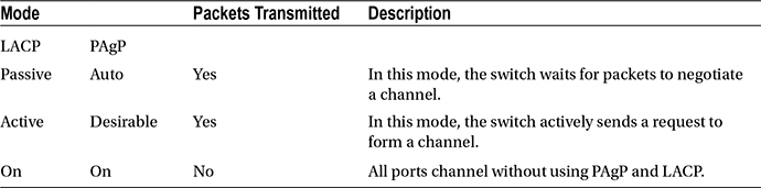
There are two protocols used for link aggregation:
- PAgP: Cisco’s proprietary Port Aggregation Protocol
- LACP: IEEE standard Link Aggregation Control Protocol
Table 5-1 describes PAgP modes.
Table 5-1. PAgP
|
Mode |
Description |
|---|---|
|
Auto |
This mode puts an interface into a passive negotiating state; the interface then responds to the PAgP packets it receives, but it cannot start negotiations. This is the default mode if not explicitly stated. |
|
Desirable |
This mode puts an interface into an active negotiation; the interface starts negotiations with other interfaces by transmitting PAgP packets. |
|
On |
This mode forces an interface to create a channel without PAgP. The interface will only create an EtherChannel if the connecting interface group mode is also set to ON. |
Table 5-2 describes LACP modes.
Table 5-2. LACP
|
Mode |
Description |
|---|---|
|
Passive |
The switch will not actively initiate a channel, but it will respond to incoming LACP packets. The peer must be in an active mode to form a channel with a peer in passive mode. Similar to auto mode in PAgP. |
|
Active |
The switch will actively send packets to initiate the negotiation of a channel. The other end of the LACP must be in active or passive mode. Similar to the PAgP desirable mode. |
|
On |
The switch forces a channel to be created without LACP negotiation. The switch will not transmit or respond to LACP packets. Similar to the PAgP On mode. |
The first example is LACP EtherChannel layer 2 configuration (see Figure 5-2).
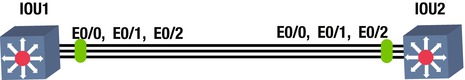
Figure 5-2. EtherChannel
In Figure 5-2, the FastEthernet0/0, 0/1 and 0/2 (on IOU1 and IOU2) must belong to VLAN 99 (VLANs are discussed in Chapter 7); it is required to create a layer 2 EtherChannel using LACP with active mode on IOU1 and passive mode on IOU2. Look at the following configuration:
IOU1
The configure terminal command is used to enter the global configuration mode.
IOU1#configure terminal
Enter configuration commands, one per line.  End with CNTL/Z.
The interface range command is used to enter the interface configuration mode, which allows you to configure multiple ports at once.
IOU1(config)# interface range ethernet0/0 – 2
IOU1(config-if-range)# no shut
The switchport mode access command is used to set the port as an access port. If more than one VLAN is used on the port, then the switchport mode trunk command should be used.
IOU1(config-if-range)# switchport mode access
The switchport access vlan 99 command places all interfaces specified in the range command in VLAN 99.
IOU1(config-if-range)# switchport access vlan 99
% Access VLAN does not exist. Creating vlan 99
The channel-protocol lacp command is used to set the port channel protocol on the interfaces.
IOU1(config-if-range)# channel-protocol lacp
The channel-group 1 mode active command adds the interfaces specified to port channel 1.
IOU1(config-if-range)# channel-group 1 mode active
Creating a port-channel interface Port-channel 1
The following message states that the remote port on IOU2 that is connected to port E0/2 on IOU1 is not configured to support an LACP port channel.
*Dec 23 06:39:49.615: %EC-5-L3DONTBNDL2: Et0/2 suspended: LACP currently not enabled on the remote port.
The following message from the switch tells you that port E0/0 is now up; you should receive another message shortly after IOU2 is configured, stating that the port channel is up.
*Dec 23 06:40:10.720: %LINEPROTO-5-UPDOWN: Line protocol on Interface Ethernet0/0, changed state to up
*Dec 23 06:40:21.456: %LINEPROTO-5-UPDOWN: Line protocol on Interface Port-channel1, changed state to up

IOU2
IOU2#configure terminal
Enter configuration commands, one per line.  End with CNTL/Z.
IOU2(config)# interface range ethernet0/0 -2
IOU2(config-if-range)#no shut
IOU2(config-if-range)# switchport mode access
IOU2(config-if-range)# switchport access vlan 99
IOU2(config-if-range)# channel-protocol lacp
Since the other port channel was configured on IOU1 in active mode, then IOU2 can be configured in either passive or active mode.
IOU2(config-if-range)# channel-group 1 mode passive
Creating a port-channel interface Port-channel 1
As expected, after IOU2 is configured, you receive another message stating that the port channel is now up.
*Dec 23 06:40:18.171: %LINEPROTO-5-UPDOWN: Line protocol on Interface Port-channel1, changed state to up
![]() Note The show etherchannel command can be used to display port-channel information after configuration. Always remember to save the configuration!
Note The show etherchannel command can be used to display port-channel information after configuration. Always remember to save the configuration!
The following output displays information such as the group state, which shows whether the EtherChannel is layer 2 (L2) or layer 3 (L3), as well as the protocol being used. See the following results of the show etherchannel command.
IOU1#sh ether?
etherchannel  ethernet

IOU1#show etherchannel
                Channel-group listing:
                ----------------------
Group: 1
----------
Group state = L2
Ports: 3   Maxports = 16
Port-channels: 1 Max Port-channels = 16
Protocol:   LACP
Minimum Links: 0
This configuration allows you to send data only for VLAN 99 over the EtherChannel link. To pass traffic for all VLANs, you must configure the switch port as a trunk because access ports only send traffic for one VLAN.
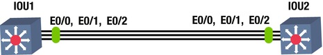
The second example is PAgP EtherChannel layer 3 configuration (see Figure 5-3).

Figure 5-3. PAgP EtherChannel
In this example, interfaces Ethernet0/0, 0/1, and 0/2 (on IOU1 and IOU2) must be aggregated to create a layer 3 EtherChannel using PAgP, with the desirable mode on IOU1 and auto mode on IOU2. See the following configuration:
IOU1
IOU1#conf terminal
Enter configuration commands, one per line.  End with CNTL/Z.
IOU1(config)# interface port-channel 1
The no switchport command is used because you want the port channel interface to be configured as a layer 3 interface on which you can directly configure an IP address.
IOU1(config-if)# no switchport
IOU1(config-if)# ip address 192.168.1.1 255.255.255.0
IOU1(config-if)# interface range ethernet0/0 -2
IOU1(config-if-range)# no shut
IOU1(config-if-range)# no switchport
IOU1(config-if-range)# no ip address
IOU1(config-if-range)# channel-group 1 mode desirable
IOU1(config-if-range)# end
The following message states that the remote port on IOU2, which is connected to port E0/1 on IOU1, is not configured to support a PAgP port channel:
*Dec 23 06:48:19.714: %EC-5-L3DONTBNDL1: Et0/1 suspended: PAgP not enabled on the remote port.

IOU1#sh etherchannel
                Channel-group listing:
                ----------------------

Group: 1
----------
Group state = L3
Ports: 3   Maxports = 8
Port-channels: 1 Max Port-channels = 1
Protocol:   PAgP
Minimum Links: 0

IOU2
IOU2#configure terminal
Enter configuration commands, one per line.  End with CNTL/Z.
IOU2(config)# interface port-channel 1
IOU2(config-if)# no switchport
The IP address is set by using the ip address command followed by the subnet mask of the network.
IOU2(config-if)# ip address 192.168.1.2 255.255.255.0
IOU2(config-if)# interface range ethernet0/0 -2
IOU2(config-if-range)#no shut
IOU2(config-if-range)# no switchport
IOU2(config-if-range)# no ip address
IOU2(config-if-range)# channel-group 1 mode auto
IOU2(config-if-range)# end
![]() Note The no switchport command is used to change an interface from layer 2 mode to layer 3 mode.
Note The no switchport command is used to change an interface from layer 2 mode to layer 3 mode.
Spanning Tree Protocol
The Spanning Tree Protocol (STP) is designed to restrict where a switch can forward frames, preventing loops in a redundant switched Ethernet local area network. STP was created because some switches would forward frames in a LAN indefinitely without intervention. While enabled, STP allows switches to block ports, which prevents them from forwarding frames if there are redundant links. Intelligent choices are made in respect to blocking ports:
- STP is made so that frames cannot loop forever or indefinitely.
- STP restricts frames from being looped continuously by checking each interface to determine if it is in a blocking state. If it is in a blocking state, all traffic is blocked and no frames will be sent or received on that interface.
Why Do You Need STP?
Without STP, Ethernet frames could potentially loop around the network forever, if LAN connections never failed. A broadcast storm is created when a frame loops continuously. It can saturate all network links, which can impact end users by making end devices process a large amount of broadcast frames.
How STP Works
STP decides which ports or interfaces should be placed in a forwarding state, with the remaining placed in a blocking state. Interfaces in a forwarding state send and receive frames, and those in a blocking state do not.
STP chooses to elect a root switch in which all of its ports are placed in the forwarding state. The election process is called a root bridge election.
A root bridge must be selected. The root bridge of the spanning tree is the bridge with the lowest bridge ID. The bridge ID is a combination of a priority number and a MAC address. The default bridge priority is 32768, which can be configured in multiples of 4096. An example bridge ID is 32768.0000.1111.2222. If two switches have the same priority, then the switch with the lowest MAC address will be the root bridge. For example, if two switches have a priority of 32768, and switch 1 has a MAC address of 0000.1111.1111 and switch 2 has MAC address 0000.1111.2222, then switch A is selected as the root bridge.
After the bridge is chosen, every bridge calculates the cost of each possible path from itself to the root to determine the least cost path to the root. All other ports that are not a root port of the designated port is disabled and put in a blocking state.
Bridge Protocol Data Units
Each bridge needs knowledge of the entire network to determine port states, including root, blocked, or designated. Information is exchanged in Bridge Protocol Data Units (BPDUs) that contain information regarding bridge IDs and root path costs. The BPDU frame’s destination address is STP multicast address 01:80:c2:00:00:00; its source address on the port is the MAC address of the switch.
- A configuration BPDU for spanning tree computation
- A topology change notification (TCN) BPDU that notifies the network of topology changes
BPDUs are transferred by default every two seconds to notify switches of network changes and to stop forwarding at disabled ports.
Let’s look at an example BPDU packet in Figure 5-4.
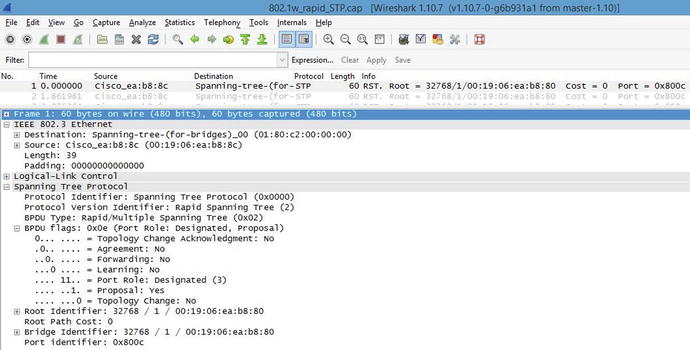
Figure 5-4. Captured BPDU packet
In Figure 5-4 you can see that the protocol is spanning tree and that the port role of the switch that sent this packet is designated. The BPDU is an Ethernet 802.3 frame. Note that the destination address is a multicast spanning tree address. Also take note of the root, bridge, and port identifiers. STP has many port states. Table 5-3 displays the switch port states in STP.
Table 5-3. STP Switch Port States
|
Blocking |
No data can be sent or received from this port unless other links fail, and STP may transition the port to the forwarding state. Looped paths are prevented by blocking a port. |
|
Listening |
In this state, the switch is able to process BPDUs and does not forward frames or populate its MAC address table. |
|
Learning |
The switch in this state does not forward frames, but it does learn source addresses from the BPDU frames received. It does not forward frames, but it does store MAC addresses in its table. |
|
Forwarding |
A port in this state can send and receive BPDU frames. |
|
Disabled |
The network administrator manually disabled a port. |
Rapid Spanning Tree Protocol
Rapid Spanning Tree Protocol (RSTP) was developed to allow switches to quickly transition into a forwarding state to prevent delays when hosts are connected to a switch or when a topology change has occurred. STP can take 30 to 50 seconds to respond to a topology change, whereas RSTP can respond to topology changes within milliseconds. Tables 5-4 and 5-5 list and define the RSTP switch port states and roles.
Table 5-4. RSTP Switch Port Roles
|
Root |
The best port from non-root to root bridge; a forwarding port. |
|
Designated |
A forwarding port for all LAN segments. |
|
Alternate |
An alternate path to the root bridge; different from the path using the root port. |
|
Backup |
A backup path to a segment where a bridge port connects. |
|
Disabled |
A manually disabled port by a network administrator. |
Table 5-5. RSTP Switch Port States
|
Discarding |
No data can be sent over a port in this state. |
|
Learning |
The port is not forwarding BPDU frames but is populating its MAC address table. |
|
Forwarding |
A fully operational port. |
Rapid Spanning Tree Protocol Configuration Example
The third example is Rapid Spanning Tree Protocol configuration (see Figure 5-5).
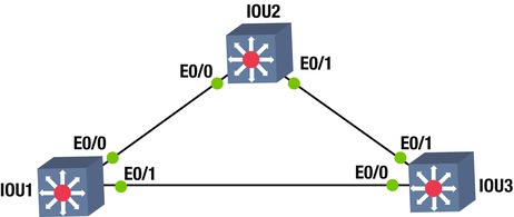
Figure 5-5. RSTP diagram
This exercise covers configuring and verifying the RSTP.
Switch 1
IOU1#configure terminal
Enter configuration commands, one per line.  End with CNTL/Z.
The spanning-tree mode rapid-pvst command enabled STP.
IOU1(config)#spanning-tree mode rapid-pvst
IOU1(config)#interface range e0/0 – 1
The spanning-tree portfast command sets the interfaces specified to portfast.
IOU1(config-if-range)#spanning-tree portfast
You will get a warning message about enabling portfast on trunk links.
%Warning: portfast should only be enabled on ports connected to a single
 host. Connecting hubs, concentrators, switches, bridges, etc... to this
 interface  when portfast is enabled, can cause temporary bridging loops.
 Use with CAUTION

%Portfast will be configured in 4 interfaces due to the range command
 but will only have effect when the interfaces are in a non-trunking mode.
Switch 2
IOU2#conf t
Enter configuration commands, one per line.  End with CNTL/Z.
IOU2(config)#spanning-tree mode rapid-rst
IOU2(config)#interface range e0/0 - 1
IOU2(config-if-range)#spanning-tree portfast
IOU2(config-if-range)# no shut
Switch 3
IOU3#conf t
Enter configuration commands, one per line.  End with CNTL/Z.
IOU3(config)#spanning-tree mode rapid-rst
IOU3(config)#interface range e0/0 - 1
IOU3(config-if-range)#spanning-tree portfast
IOU3(config-if-range)#no shut
IOU3(config-if-range)#end
Switch 1 is the root bridge.
The show spanning-tree command can be used to display information about STP, including the root ID, bridge ID, and the interfaces running STP.
IOU1#sh spanning-tree

VLAN0001
  Spanning tree enabled protocol rstp
  Root ID    Priority    32769
             Address     aabb.cc00.0100
             This bridge is the root
             Hello Time   2 sec  Max Age 20 sec  Forward Delay 15 sec

  Bridge ID  Priority    32769  (priority 32768 sys-id-ext 1)
             Address     aabb.cc00.0100
             Hello Time   2 sec  Max Age 20 sec  Forward Delay 15 sec
             Aging Time  300 sec

Interface           Role Sts Cost      Prio.Nbr Type
------------------- ---- --- --------- -------- --------------------------------
Et0/0               Desg FWD 100       128.1    Shr
Et0/1               Desg FWD 100       128.2    Shr Edge
Currently, switch 1 is the root switch. Now you can force switch 3 to become the root switch. This can be done in two ways: you can set the priority of the VLAN to a much lower value by using the priority command, or you can force the switch by using the primary command.
IOU3#configure terminal
Enter configuration commands, one per line.  End with CNTL/Z.
IOU3(config)#spanning-tree vlan 1 priority 4096
IOU3(config)#end
IOU3#show spanning-tree

VLAN0001
  Spanning tree enabled protocol rstp
  Root ID    Priority    4097
             Address     aabb.cc00.0300
             This bridge is the root
             Hello Time   2 sec  Max Age 20 sec  Forward Delay 15 sec

  Bridge ID  Priority    4097   (priority 4096 sys-id-ext 1)
             Address     aabb.cc00.0300
             Hello Time   2 sec  Max Age 20 sec  Forward Delay 15 sec
             Aging Time 300

Interface           Role Sts Cost      Prio.Nbr Type
------------------- ---- --- --------- -------- --------------------------------
Et0/0               Desg FWD 100       128.1    Shr Edge
Et0/1               Desg LRN 100       128.2    Shr
Now set up switch 2 to be the root bridge using the primary command.
IOU2#configure terminal
Enter configuration commands, one per line.  End with CNTL/Z.
IOU2(config)#spanning-tree vlan 1 root primary
IOU2(config)#end
IOU2#sh spanning-tree vlan 1

VLAN0001
  Spanning tree enabled protocol rstp
  Root ID    Priority    4097
             Address     aabb.cc00.0200
             This bridge is the root
             Hello Time   2 sec  Max Age 20 sec  Forward Delay 15 sec

  Bridge ID  Priority    4097   (priority 4096 sys-id-ext 1)
             Address     aabb.cc00.0200
             Hello Time   2 sec  Max Age 20 sec  Forward Delay 15 sec
             Aging Time 300

Interface           Role Sts Cost      Prio.Nbr Type
------------------- ---- --- --------- -------- --------------------------------
Et0/0               Desg BLK 100       128.1    Shr
Et0/1               Desg FWD 100       128.2    Shr
![]() Note Portfast is enabled on the access ports. This enables ports to go straight to a forwarding state, meaning the ports will instantly come up. Do not enable on trunk ports; this may cause issues with switching loops.
Note Portfast is enabled on the access ports. This enables ports to go straight to a forwarding state, meaning the ports will instantly come up. Do not enable on trunk ports; this may cause issues with switching loops.
Exercises
This section provides exercises to reinforce what is covered this chapter.
EXERCISE 1 / ETHERCHANNEL LACP
Company ABC would like to enable redundancy on the backbone interfaces between two core switches. Enable EtherChannel using LACP. Create VLAN 99 on interfaces E0/0, E0/1, and E0/2 on IOU1 and IOU2. Use the following diagram for this exercise.
EXERCISE 2 / ETHERCHANNEL PAGP
Company ABC would like to enable redundancy on the backbone interfaces between two core switches. Enable EtherChannel using PAgP. Use the IP subnet 192.168.2.0/30 noted in the following diagram for the port channel interfaces on IOU1 and IOU2. Configure interfaces E0/0, E0/1, and E0/2 on IOU1 and IOU2 to support the port channel.

EXERCISE 3 / SPANNING-TREE
Company ABC needs to set up spanning-tree in its switched network. Using the following diagram, enable the spanning-tree protocol on all switches. Configure interface E0/0 and E0/1 to support STP on IOU1, IOU2, IOU3, IOU4, and IOU5. If switch IOU1 is not the root switch, force this switch to become the root switch.
Exercise Answers
This section provides the answers to the preceding exercises.
Exercise 1
Company ABC would like to enable redundancy on the backbone interfaces between two core switches. Enable EtherChannel using LACP. Create VLAN 99 on interfaces E0/0, E0/1, and E0/2 on IOU1 and IOU2. Figure 5-6 is used for the exercise.

Figure 5-6. EtherChannel answer diagram
IOU1
IOU1#configure terminal
IOU1(config)# interface range ethernet0/0 – 2
IOU1(config-if-range)# no shut
IOU1(config-if-range)# switchport mode access
IOU1(config-if-range)# switchport access vlan 99
IOU1(config-if-range)# channel-protocol lacp
IOU1(config-if-range)# channel-group 1 mode active
IOU2
IOU2#configure terminal
IOU2(config)# interface range ethernet0/0 -2
IOU2(config-if-range)#no shut
IOU2(config-if-range)# switchport mode access
IOU2(config-if-range)# switchport access vlan 99
IOU2(config-if-range)# channel-protocol lacp
IOU2(config-if-range)#  channel-group 1 mode passive
Exercise 2
Company ABC would like to enable redundancy on the backbone interfaces between two core switches. Enable EtherChannel using PAgP. Use the IP subnet 192.168.2.0/30 noted in Figure 5-7 for port channel interfaces on IOU1 and IOU2. Configure interfaces E0/0, E0/1 and E0/2 on IOU1 and IOU2 to support the port channel. Figure 5-7 is used for this exercise.
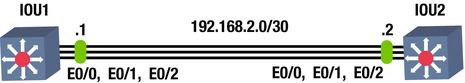
Figure 5-7. EtherChannel PAgP answer diagram
IOU1
IOU1#configure terminal
IOU1(config)# interface port-channel 1
IOU1(config-if)# no switchport
IOU1(config-if)# ip address 192.168.2.1 255.255.255.0
IOU1(config-if)# interface range ethernet0/0 - 2
IOU1(config-if-range)# no shut
IOU1(config-if-range) # no switchport
IOU1(config-if-range)# no ip address
IOU1(config-if-range)# channel-group 1 mode desirable
IOU1(config-if-range)# end
IOU2
IOU2#configure terminal
IOU2(config)# interface port-channel 1
IOU2(config-if)# no switchport
IOU2(config-if)# ip address 192.168.2.2 255.255.255.0
IOU2(config-if)# interface range ethernet0/0 - 2
IOU2(config-if-range)#no shut
IOU2(config-if-range)# no switchport
IOU2(config-if-range)# no ip address
IOU2(config-if-range)# channel-group 1 mode auto
IOU2(config-if-range)# end
Exercise 3
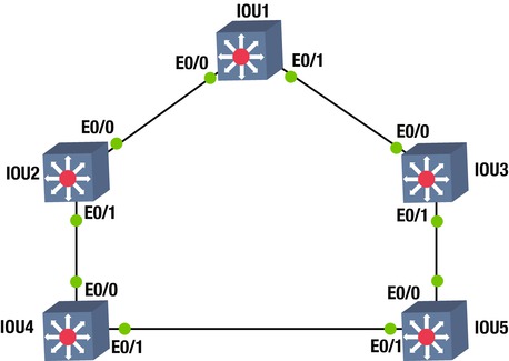
Company ABC needs to set up spanning-tree in their switched network. Using the following diagram, enable the spanning-tree protocol on all switches. Configure interface E0/0 and E0/1 to support STP on IOU1, IOU2, IOU3, IOU4, and IOU5. If switch IOU1 is not the root switch, force this switch to become the root switch. Figure 5-8 is used for this exercise.

Figure 5-8. STP answer diagram
IOU1
configure terminal
spanning-tree mode rapid-pvst
interface range e0/0 - 1
spanning-tree portfast
no shut
IOU2
configure terminal
spanning-tree mode rapid-pvst
interface range e0/0 - 1
spanning-tree portfast
no shut
IOU3
configure terminal
spanning-tree mode rapid-pvst
interface range e0/0 - 1
spanning-tree portfast
no shut
IOU4
configure terminal
spanning-tree mode rapid-pvst
interface range e0/0 - 1
spanning-tree portfast
no shut
IOU5
configure terminal
spanning-tree mode rapid-pvst
interface range e0/0 - 1
spanning-tree portfast
no shut
To configure IOU1 as the root switch:
IOU1
configure terminal
spanning-tree vlan 1 root primary
Summary
This chapter introduced the Cisco IOS software, including how to access a Cisco device. Switching concepts were also discussed, including EtherChannels and STP, RSTP, and BPDUs. Remember that the EtherChannel allows you to add redundancy in your switched network. The two modes of EtherChannel are LACP and PAgP. Table 5-6 is a summary of the EtherChannel modes LACP and PAgP.
Table 5-6. EtherChannel Modes