![]()
Data Center and NX-OS
This chapter discusses the next generation operation system relied upon in many data centers worldwide. The operating system is called NX-OS; it is used in Cisco Nexus switches. NX-OS is similar to Cisco IOS, but different enough to frustrate regular users of Cisco IOS. Some of the commands are the same but others are entirely different. This chapter covers these differences and many of the concepts already covered for IOS, including VLANs, VTP, EIGRP, OSPF, BGP, port channels, port profiles, Fabric Extenders (FEX), Hot Standby Redundancy Protocols (HSRP), virtual device context (VDC), virtual port channels (vPC), and VRF-lite (virtual routing and forwarding).
NX-OS
NX-OS is a Linux-based operating system (OS). It is made efficient in that when Nexus is booted, the OS does not load unnecessary features. For instance, if you want to configure TACACS, you need to enable this feature using the feature command. This means the device runs faster because there is no unnecessary code being run. The following output shows the different features that have to be enabled on Nexus to use them.
Nexus(config)# feature ?
  bfd             Bfd
  bgp             Enable/Disable Border Gateway Protocol (BGP)
  cts             Enable/Disable CTS
  dhcp            Enable/Disable DHCP Snooping
  dot1x           Enable/Disable dot1x
  eigrp           Enable/Disable Enhanced Interior Gateway Routing Protocol
                  (EIGRP)
  eou             Enable/Disables feature l2nac(eou)
  fip-snooping    Enable/Disable fip-snooping(FCoE Initializtion Protocol)
  glbp            Enable/Disable Gateway Load Balancing Protocol (GLBP)
  hsrp            Enable/Disable Hot Standby Router Protocol (HSRP)
  interface-vlan  Enable/Disable interface vlan
  isis            Enable/Disable IS-IS Unicast Routing Protocol (IS-IS)
  lacp            Enable/Disable LACP
  ldap            Enable/Disable ldap
  lldp            Enable/Disable LLDP
  msdp            Enable/Disable Multicast Source Discovery Protocol (MSDP)
  netflow         Enable/Disable NetFlow
  ospf            Enable/Disable Open Shortest Path First Protocol (OSPF)
  ospfv3          Enable/Disable Open Shortest Path First Version 3 Protocol
                  (OSPFv3)
  otv             Enable/Disable Overlay Transport Virtualization (OTV)
  pbr             Enable/Disable Policy Based Routing(PBR)
  pim             Enable/Disable Protocol Independent Multicast (PIM)
  pim6            Enable/Disable Protocol Independent Multicast (PIM) for IPv6
  port-security   Enable/Disable port-security
  private-vlan    Enable/Disable private-vlan
  privilege       Enable/Disable IOS type privilege level support
  rip             Enable/Disable Routing Information Protocol (RIP)
  scheduler       Enable/Disable scheduler
  scp-server      Enable/Disable SCP server
  sftp-server     Enable/Disable SFTP server
  ssh             Enable/Disable ssh
  tacacs+         Enable/Disable tacacs+
  telnet          Enable/Disable telnet
  tunnel          Enable/Disable Tunnel Manager
  udld            Enable/Disable UDLD
  vpc             Enable/Disable VPC (Virtual Port Channel)
  vrrp            Enable/Disable Virtual Router Redundancy Protocol (VRRP)
  vtp             Enable/Disable VTP
  wccp            Enable/Disable Web Cache Communication Protocol (WCCP)
You can see that features such as BGP, OSPF, Telnet, SSH, LACP and EIGRP are not enabled by default.
The interface range command is also no longer recognized in Nexus. Instead, you type the starting interface, followed by a dash and the last interface of the range, as shown here.
Nexus(config)# int e2/1 -5
Nexus(config-if-range)#
We all like to use the write memory command to save the configuration but this command is not valid in NX-OS. Instead, you must use the copy running-config startup-config command.
Nexus# copy running-config startup-config
[########################################] 100%

Copy complete, now saving to disk (please wait)...
The show ip interface brief command is a favorite command to use in IOS, but this command is not the same in NX-OS. The show interface brief command is used instead.
Nexus# show interface brief

--------------------------------------------------------------------------------
Port   VRF          Status IP Address                              Speed    MTU
--------------------------------------------------------------------------------
mgmt0  --           up     192.168.1.101                           --       1500

---------------------------------------------------------------------------------
Ethernet      VLAN    Type Mode   Status  Reason                   Speed     Port
Interface                                                                    Ch
#
--------------------------------------------------------------------------------
Eth2/1        --      eth  routed down    Administratively down      auto(D) --
Eth2/2        --      eth  routed down    Administratively down      auto(D) --
Eth2/3        --      eth  routed down    Administratively down      auto(D) --
Eth2/4        --      eth  routed down    Administratively down      auto(D) --
Eth2/5        --      eth  routed down    Administratively down      auto(D) --
Eth2/6        --      eth  routed down    Administratively down      auto(D) --
Eth2/7        --      eth  routed down    Administratively down      auto(D) --
Eth2/8        --      eth  routed down    Administratively down      auto(D) --
Eth2/9        --      eth  routed down    Administratively down      auto(D) --
The command show arp has also been changed. Now you use show ip arp for basic ARP information. You can also use show tech-support arp for detailed ARP information about the switch.
Switch1# show ip arp

Flags: * - Adjacencies learnt on non-active FHRP router
       + - Adjacencies synced via CFSoE
       # - Adjacencies Throttled for Glean
       D - Static Adjacencies attached to down interface

IP ARP Table for context default
Total number of entries: 1
Address         Age       MAC Address     Interface
192.168.1.2     00:00:21  fa16.3e2c.b807  Vlan100
Switch1#
Another interesting difference is that Nexus recognizes the slash for IP addresses, which helps those who have trouble subnetting or determining the subnet mask.
Nexus(config)# int e2/1
Nexus(config-if)# ip address 192.168.2.1/28
To enable SSH, you must enable the feature first.
Nexus(config)# feature ssh
Nexus(config)# ssh key rsa 2048
To enable Telnet, you must enable the feature first.
Nexus(config)# feature telnet
Now you can set the username and password of a user, which is done a little differently than in IOS.
Nexus(config)# username admin ?
  <CR>
  expire       Expiry date for this user account(in YYYY-MM-DD format)
  keypair      Generate SSH User Keys
  password     Password for the user
  role         Role which the user is to be assigned to
  ssh-cert-dn  Update cert dn
  sshkey       Update ssh key for the user for ssh authentication
The network-admin user role is a super-user; it has full read and write access to the switch.
The network-operator user role has only read access to the switch. You can see the default roles in Nexus priv-0 to priv-15.
Nexus(config)# username admin role ?
  network-admin     System configured role
  network-operator  System configured role
  priv-0            Privilege role
  priv-1            Privilege role
  priv-10           Privilege role
  priv-11           Privilege role
  priv-12           Privilege role
  priv-13           Privilege role
  priv-14           Privilege role
  priv-15           Privilege role
  priv-2            Privilege role
  priv-3            Privilege role
  priv-4            Privilege role
  priv-5            Privilege role
  priv-6            Privilege role
  priv-7            Privilege role
  priv-8            Privilege role
  priv-9            Privilege role
  vdc-admin         System configured role
  vdc-operator      System configured role

Nexus(config)# username admin role network-admin ?
  <CR>
  expire    Expiry date for this user account(in YYYY-MM-DD format)
  password  Password for the user
You can also set a date on which the user’s password expires.
Nexus(config)# username admin role network-admin password ?
  0     Indicates that the password that follows should be in clear text
  5     Indicates that the password that follows should be encrypted
  WORD  Password for the user (clear text) (Max Size 64)

Nexus(config)# username admin role network-admin password enable
Another difference in the NX-OS software is how you add static routes. Instead of including the subnet mask, you now simply add a slash notation of the mask, as follows.
Nexus(config)# ip route 192.168.3.0/24 192.168.2.1
VLAN
VLAN configuration in Nexus is the same as it is in Cisco IOS. An example configuration is provided next.
Create VLAN 100 and name it as follows.
Nexus(config)# vlan 100
Nexus(config-vlan)# name Apress_HR_Users
A group of VLANs can be created at one time.
Nexus(config-vlan)# vlan 2-20
Now you create a switchport and trunk port similar to how you completed this task in IOS to associate VLAN 100 with.
The following is the switchport configuration.
Nexus(config-if)# int e2/2
Nexus(config-if)# switchport
Nexus(config-if)# switchport access vlan 100
This is the trunk configuration.
Nexus(config-if)# int e2/2
Nexus(config-if)# switchport mode trunk
Nexus(config-if)# switchport trunk allowed vlan 100
Configuring a VLAN As a Routed Switched Virtual Interface (SVI)
Now you will configure a VLAN as a routed SVI. Do not forget to enable the interface-vlan feature; otherwise, the NX-OS software will not recognize the interface vlan command.
Nexus(config)# feature interface-vlan
Nexus(config)# interface vlan 100
Nexus(config-if)# ip address 192.168.1.1/24
In IOS, the ip helper-address command is used to forward all UDP broadcasts to a specified address including DHCP requests. In NX-OS, the ip dhcp relay address command is used to forward only DHCP broadcasts. Of course, the DHCP feature must be activated. The command can be seen in the following.
Nexus(config)# feature dhcp
Nexus(config)# interface vlan 200
Nexus(config-if)# ip dhcp relay address 192.168.1.100
The show ip dhcp relay command displays all DHCP-relay configuration information.
The VTP configuration on Nexus is the same as in Cisco IOS. The following is a refresher example of configuring it on Nexus. Again, you must enable the feature first.
Nexus(config)# feature vtp
Nexus(config)# vtp domain Apress
Nexus(config)# vtp mode ?
  client       Set the device to client mode
  off          Set the device to off mode
  server       Set the device to server mode
  transparent  Set the device to transparent mode

Nexus(config)# vtp mode server
Use Figure 19-1 to configure switch NX2 as an example VTP server.
NX2(config)# feature vtp
NX2(config)# vtp domain Apress
NX2(config)# vtp mode server

Figure 19-1. VTP diagram
You set this switch as the VTP server; the other switch is set as a client.
NX1(config)# feature vtp
NX1(config)# vtp domain Apress
NX1(config)# vtp mode client
You can see information regarding the VTP status by using the show vtp command. You can also see the different options that can be used with this command.
NX2(config)# sh vtp ?
*** No matching command found in current mode, matching in (exec) mode ***
  counters   VTP statistics
  interface  VTP interface status and configuration
  internal   Show internal information
  password   VTP password
  status     VTP domain status

NX2(config)# sh vtp status
VTP Status Information
----------------------
VTP Version                     : 2 (capable)
Configuration Revision          : 0
Maximum VLANs supported locally : 1005
Number of existing VLANs        : 5
VTP Operating Mode              : Server
VTP Domain Name                 : Apress
VTP Pruning Mode                : Disabled (Operationally Disabled)
VTP V2 Mode                     : Disabled
VTP Traps Generation            : Disabled
MD5 Digest                      : 0xD3 0x8A 0xE5 0xFA 0xE4 0x9F 0x94 0x53
Configuration last modified by 192.168.1.3 at 0-0-00 00:00:00
Local updater ID is 192.168.1.3
VTP version running             : 1
From the output of the show vtp status command, you can see that switch NX2 is in server mode, the domain is Apress, and the switch is running VTP version 1.
NX1(config-if)# sh vtp counters
VTP statistics:
Summary advertisements received    : 1
Subset advertisements received     : 0
Request advertisements received    : 0
Summary advertisements transmitted : 2
Subset advertisements transmitted  : 0
Request advertisements transmitted : 0
Number of config revision errors   : 1
Number of config digest errors     : 0
Number of V1 summary errors        : 0
By using the show vtp counters command, you can see that switch NX1 is receiving VTP information.
EIGRP
The EIGRP router process in configured in global mode, but adding interfaces to EIGRP is completed in interface configuration mode. Do not forget to enable EIGRP.
Nexus(config-line)# feature eigrp
LAN_ENTERPRISE_SERVICES_PKG license not installed. eigrp feature will be shutdown after grace period of approximately 119 day(s)
Placing an interface in EIGRP must be completed in interface configuration mode on Nexus. You can create the EIGRP process using an alphanumeric string or with the AS number. If you use an alphanumeric string, the autonomous system command must be used to set the AS number for the EIGRP process.
Nexus(config)# router eigrp ?
  1 (no abbrev)  EIGRP process tag
  WORD           Process tag (Max Size 20)

Nexus(config)# router eigrp Apress
Nexus(config-router)# autonomous-system 1

Nexus(config)# router eigrp 1
Options that can be configured in router configuration mode include authentication, a default route, a default-metric for redistributed routes, redistribution, stub routing, and the router-id. All options can be seen if you type the ? command.
Nexus(config-router)# ?
  address-family         Configure an address-family
  authentication         Configures EIGRP authentication subcommands
  autonomous-system      Specify AS number for Address Family
  default-information    Control origination of a default route
  default-metric         Set metric of redistributed routes
  distance               Define an administrative distance
  flush-routes           Flush routes in RIB during restart
  graceful-restart       Peer resync without adjancency reset
  log-adjacency-changes  Log changes in adjacency state
  log-neighbor-warnings  Enable/Disable IP-EIGRP neighbor warnings
  maximum-paths          Forward packets over multiple paths
  metric                 Modify EIGRP routing metrics and parameters
  no                     Negate a command or set its defaults
  redistribute           Redistribute information from another routing protocol
  router-id              Router-id for this EIGRP process
  shutdown               Shutdown this instance of EIGRP
  stub                   Set IP-EIGRP as stubbed router
  this                   Shows info about current object (mode’s instance)
  timers                 Set EIGRP timers
  vrf                    Configure VRF information
  end                    Go to exec mode
  exit                   Exit from command interpreter
  pop                    Pop mode from stack or restore from name
  push                   Push current mode to stack or save it under name
  where                  Shows the cli context you are in
Finally, an interface is added to EIGRP by using the router eigrp command in interface configuration mode.
Nexus(config-router)# int e2/1
Nexus(config-if)# router eigrp 1
Use Figure 19-2 to configure the example.

Figure 19-2. EIGRP diagram
You will now configure EIGRP on NX1 and NX2 based on Figure 19-2; use the commands covered in this section. The following is the EIGRP configuration.
NX2(config)# feature eigrp
After enabling EIGRP, configure the EIGRP instance and the router ID.
NX2(config)# router eigrp 1
NX2(config-router)# router-id 1.1.1.1
Now you can configure an IP address on the interfaces that will participate in EIGRP, and associate those networks with EIGRP using the ip router eigrp command.
NX2(config-router)# int e2/1
NX2(config-if)# ip add 192.168.6.1/24
NX2(config-if)# ip router eigrp 1
You can configure a passive interface to prevent unnecessary traffic by using the ip passive-interface eigrp command.
NX2(config-if)# ip passive-interface eigrp 1
NX2(config-if)# int e2/6
NX2(config-if)# ip add 192.168.3.1/24
NX2(config-if)# ip router eigrp 1

NX1(config-if)# feature eigrp
NX1(config)# router eigrp 1
NX1(config-router)# router-id 2.2.2.2
NX1(config-router)# int e2/1
NX1(config-if)# ip add 192.168.5.1/24
NX1(config-if)# ip router eigrp 1
NX1(config-if)# ip passive-interface eigrp 1
NX1(config-if)# int e2/6
NX1(config-if)# ip add 192.168.3.2/24
NX1(config-if)# ip router eigrp 1
Now that you have configured EIGRP, you can verify the neighbor relationship between NX1 and NX2. To view the status of EIGRP, you use the show ip eigrp command. The question mark displays the options you can display.
NX1(config-if)# sh ip eigrp ?
*** No matching command found in current mode, matching in (exec) mode ***
  <CR>
  1              EIGRP process tag
  >              Redirect it to a file
  >>             Redirect it to a file in append mode
  accounting     IP-EIGRP Accounting
  event-history  Show event history of EIGRP
  interfaces     IP-EIGRP interfaces
  internal       Show internal information
  neighbors      IP-EIGRP neighbors
  route          IP-EIGRP internal routes
  route-map      Route-map related information
  topology       IP-EIGRP Topology Table
  traffic        IP-EIGRP Traffic Statistics
  vrf            Display per-VRF information
  |              Pipe command output to filter
You use the show ip eigrp neighbors and topology commands for verification.
NX1(config-if)# sh ip eigrp neighbors
IP-EIGRP neighbors for process 1 VRF default
H   Address                 Interface       Hold  Uptime  SRTT   RTO  Q  Seq
                                            (sec)         (ms)       Cnt Num
0   192.168.3.1             Eth2/6          12   00:00:48  2    200   0   3
Using the show ip eigrp neighbors command that you have verified that the EIGRP neighbor adjacency is up from NX1 to NX2. Now let’s verify that you have all networks in the topology.
NX1(config-if)# sh ip eigrp topology
IP-EIGRP Topology Table for AS(1)/ID(2.2.2.2) VRF default

Codes: P - Passive, A - Active, U - Update, Q - Query, R - Reply,
       r - reply Status, s - sia Status

P 192.168.5.0/24, 1 successors, FD is 2816
        via Connected, Ethernet2/1
P 192.168.6.0/24, 1 successors, FD is 3072
        via 192.168.3.1 (3072/2816), Ethernet2/6
P 192.168.3.0/24, 1 successors, FD is 2816
        via Connected, Ethernet2/6
From Figure 19-2,you can see that you have all the networks that you should. EIGRP is functioning properly.
Now let’s add authentication to the EIGRP configuration.
You start by configuring the key chain and the key-string. The key-string must be the same on both devices.
NX1(config)# key chain mykey
NX1(config-keychain)# key 1
NX1(config-keychain-key)# key-string ThisIsTheKey
Now you configure MD5 authentication on the interface that creates the neighbor adjacency, and reference the key chain you created.
NX1(config-keychain-key)# int e2/6
NX1(config-if)# ip authentication mode eigrp 1 ?
  md5  Keyed message digest

NX1(config-if)# ip authentication mode eigrp 1 md5
NX1(config-if)# ip authentication key-chain eigrp 1 mykey

NX2(config)# key chain mykey
NX2(config-keychain)# key 1
NX2(config-keychain-key)# key-string ThisIsTheKey
NX2(config-keychain-key)# int e2/6
NX2(config-if)# ip authentication mode eigrp 1 md5
NX2(config-if)# ip authentication key-chain eigrp 1 mykey
You can verify that you are using the key chain by using the show ip eigrp interfaces detail command.
NX1(config-if)# sh ip eigrp interfaces detail
IP-EIGRP interfaces for process 1 VRF default

                        Xmit Queue   Mean   Pacing Time   Multicast    Pending
Interface        Peers  Un/Reliable  SRTT   Un/Reliable   Flow Timer   Routes
Eth2/6             1        0/0         2       0/1         50             0
  Hello interval is 5 sec
  Holdtime interval is 15 sec
  Next xmit serial <none>
  Un/reliable mcasts: 0/2  Un/reliable ucasts: 4/5
  Mcast exceptions: 0  CR packets: 0  ACKs suppressed: 2
  Retransmissions sent: 1  Out-of-sequence rcvd: 1
  Authentication mode is md5,  key-chain is "mykey"
OSPF
The OSPF router process in configured in global mode, but adding interfaces to OSPF is completed in interface configuration mode. Do not forget to enable OSPF.
Nexus(config)# feature ospf
Nexus(config)# router ospf 1
Options that can be configured in router configuration mode include area properties, default routes, a default-metric for redistributed routes, redistribution, and the router ID.
Nexus(config-router)# ?
  area                   Configure area properties
  auto-cost              Calculate OSPF cost according to bandwidth
  default-information    Control distribution of default route
  default-metric         Specify default metric for redistributed routes
  distance               OSPF administrative distance
  flush-routes           Flush routes on a non-graceful controlled restart
  graceful-restart       Configure graceful restart
  ip                     IP events
  log-adjacency-changes  Log changes in adjacency state
  max-metric             Maximize the cost metric
  maximum-paths          Maximum paths per destination
  no                     Negate a command or set its defaults
  redistribute           Redistribute information from another routing protocol
  rfc1583compatibility   Configure 1583 compatibility for external path
                         preferences
  router-id              Set OSPF process router-id
  shutdown               Shutdown the OSPF protocol instance
  summary-address        Configure route summarization for redistribution
  this                   Shows info about current object (mode’s instance)
  timers                 Configure timer related constants
  vrf                    Display per-VRF information
  end                    Go to exec mode
  exit                   Exit from command interpreter
  pop                    Pop mode from stack or restore from name
  push                   Push current mode to stack or save it under name
  where                  Shows the cli context you are in
The area command can be used to configure authentication for an area, creating a virtual link or configuring the area as a not so stubby or stub area.
Nexus(config-router)# area 0 ?
  authentication  Enable authentication for the area
  default-cost    Specify default-cost for default summary LSA
  filter-list     Filter prefixes between OSPF areas
  nssa            Configure area as NSSA
  range           Configure an address range for an area
  stub            Configure area as a stub
  virtual-link    Define a virtual link and its parameters
Placing an interface in OSPF must be completed in interface configuration mode on Nexus. Other options that must be configured in this mode are authentication, hello and dead intervals, passive interfaces, and router priority.
Nexus(config-router)# int e2/1
Nexus(config-if)# ip router ospf 1 area 0
Nexus(config-if)# ip ospf ?
  authentication       Authentication on the interface
  authentication-key   Configure the authentication key for the interface
  cost                 Cost associated with interface
  dead-interval        Dead interval
  hello-interval       Hello interval
  message-digest-key   Message digest authentication password (key)
  mtu-ignore           Disable OSPF MTU mismatch detection
  network              Network type
  passive-interface    Suppress routing updates on the interface
  priority             Router priority
  retransmit-interval  Packet retransmission interval
  shutdown             Shutdown ospf on this interface
  transmit-delay       Packet transmission delay
Use Figure 19-3 to configure the example.

Figure 19-3. OSPF diagram
Configure OSPF on NX1 and NX2 based on Figure 19-3; use the commands covered in this section. The following is the OSPF configuration.
NX1(config)# feature ospf
Configure the OSPF instance and router ID.
NX1(config)# router ospf 1
NX1(config-router)# router-id 2.2.2.2
NX1(config-router)# int e2/1
NX1(config-if)# ip add 192.168.6.1/24
Associate the 192.168.6.0/24 and 192.168.2.0/24 networks with an OSPF instance and area 0. Then configure interface int e2/1 to be passive.
NX1(config-if)# ip router ospf 1 area 0
NX1(config-if)# ip ospf passive-interface
NX1(config-if)# int e2/6
NX1(config-if)# ip add 192.168.2.1/24
NX1(config-if)# ip router ospf 1 area 0

NX2(config-if)# feature ospf
NX2(config)# router ospf 1
NX2(config-router)# router-id 1.1.1.1
NX2(config-router)# int e2/1
NX2(config-if)# ip add 192.168.5.1/24
NX2(config-if)# ip router ospf 1 area 0
NX2(config-if)# ip ospf passive-interface
NX2(config-if)# no shut
NX2(config-if)# int e2/6
NX2(config-if)# ip add 192.168.2.2/24
NX2(config-if)# ip router ospf 1 area 0
NX2(config-if)#
Using the show ip ospf neighbor command, you can verify that OSPF is working properly.
NX2(config-if)# sh ip ospf neighbor
 OSPF Process ID 1 VRF default
 Total number of neighbors: 1
 Neighbor ID     Pri State            Up Time  Address         Interface
 2.2.2.2           1 FULL/DR          00:01:06 192.168.2.1     Eth2/6
You can see that NX2 has NX1 as an OSPF neighbor. Now you can verify the routing table.
NX2(config-if)# sh ip route
IP Route Table for VRF "default"
'*' denotes best ucast next-hop
'**' denotes best mcast next-hop
'[x/y]' denotes [preference/metric]

192.168.2.0/24, ubest/mbest: 1/0, attached
    *via 192.168.2.2, Eth2/6, [0/0], 00:01:27, direct
192.168.2.2/32, ubest/mbest: 1/0, attached
    *via 192.168.2.2, Eth2/6, [0/0], 00:01:27, local
192.168.5.0/24, ubest/mbest: 1/0, attached
    *via 192.168.5.1, Eth2/1, [0/0], 00:01:38, direct
192.168.5.1/32, ubest/mbest: 1/0, attached
    *via 192.168.5.1, Eth2/1, [0/0], 00:01:38, local
192.168.6.0/24, ubest/mbest: 1/0
    *via 192.168.2.1, Eth2/6, [110/80], 00:01:04, ospf-1, intra
You can see that you are receiving all networks from Figure 19-3.
Now you can add authentication; start with NX1.
NX1(config-if)# int e2/6
The ip ospf authentication message-digest command must be used in interface configuration mode to enable authentication.
NX1(config-if)# ip ospf authentication message-digest
Next, the ip ospf message-digest-key 1 md5 command is used, followed by the key. In this example, the key is ThisIsTheKey.
NX1(config-if)# ip ospf message-digest-key 1 md5 ?
  0     Specifies an UNENCRYPTED the ospf password (key) will follow
  3     Specifies an 3DES ENCRYPTED the ospf password (key) will follow
  7     Specifies a Cisco type 7  ENCRYPTED the ospf password (key) will follow
  LINE  The UNENCRYPTED (cleartext) the ospf password (key)

NX1(config-if)# ip ospf message-digest-key 1 md5 ThisIsTheKey
If you want to enable authentication by area instead of per interface, use the area X authentication command under the OSPF process.
NX1(config)# router ospf 1
NX1(config-router)# area 0 authentication message-digest
Notice that the message-digest command must be used to enable encryption; otherwise, the authentication is in clear text. For clear-text configuration use the following:
NX1(config-if)# int e2/6
NX1(config-if)# ip ospf authentication
NX1(config-if)# ip ospf authentication-key ThisIsTheKey
For area clear-text configuration use this:
NX1(config-if)# int e2/6
NX1(config-if)# ip ospf authentication-key ThisIsTheKey
NX1(config)# router ospf 1
NX1(config-router)# area 0 authentication
Now you can configure NX2 using MD5.
NX2(config-if)# int e2/6
NX2(config-if)# ip ospf authentication message-digest
NX2(config-if)#  ip ospf message-digest-key 1 md5 ThisIsTheKey
BGP
The BGP router process in configured in global mode. Do not forget to enable BGP.
Nexus(config-if)# feature bgp
LAN_ENTERPRISE_SERVICES_PKG license not installed. bgp feature will be
+after grace period of approximately 119 day(s)
When a license is not installed in Nexus, you are able to use the feature for approximately 119 days; after which you need to install a license to continue using that feature. If the command no feature bgp is typed, all related BGP information will be erased from the configuration.
The BGP process is created just as it is in IOS, with the router bgp command.
Nexus(config)# router bgp 1
Options that are configured for BGP in router configuration mode are the address-family, the BPG neighbor, and the router-id.
The neighbor can be created by using the neighbor command, just as in IOS.
Nexus(config)# router bgp 1
Nexus(config-router)# neighbor 192.168.1.2 remote-as 10
Nexus(config-router-neighbor)# address-family ipv4 unicast
Nexus(config-router-af)# network 192.168.1.0/24
To originate a default route to this peer, use the default-originate command.
Nexus(config-router-neighbor-af)# default-originate
To configure authentication, the password command is used.
Nexus(config-router-neighbor-af)# password test
Use Figure 19-4 to configure an example.
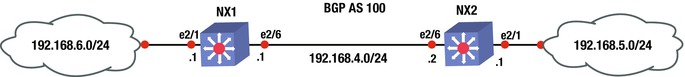
Figure 19-4. BGP diagram
Configure BGP on NX1 and NX2 based on Figure 19-4; use the commands covered in this section.
This is the BGP configuration.
NX2(config-if)# feature bgp
NX2(config)# int e2/6
NX2(config-if)# ip add 192.168.4.2/24
NX2(config-if)# no shut
NX2(config-if)# int e2/1
NX2(config-if)# ip add 192.168.5.1/24
NX2(config-if)# no shut
First, configure the BGP instance on the switch.
NX2(config-if)# router bgp 100
Now you can advertise the 192.168.4.0/24 and 192.168.5.0/24 networks in address family IPv4 by using the address family command and then specifying the networks that you want advertised.
NX2(config-router)# address-family ipv4 unicast
NX2(config-router-af)# network 192.168.4.0/24
NX2(config-router-af)# network 192.168.5.0/24
Now you can configure the internal BGP neighbor using the neighbor command followed by the IP address of the neighbor and the remote-as, which should be the same since this is internal BGP.
NX2(config-router-af)# neighbor 192.168.4.1 remote-as 100
NX2(config-router-neighbor)# address-family ipv4 unicast

NX1(config-if)# feature bgp
NX1(config)# int e2/1
NX1(config-if)# no shut
NX1(config-if)# ip add 192.168.6.1/24
NX1(config-if)# int e2/6
NX1(config-if)# no shut
NX1(config-if)# ip add 192.168.4.1/24
NX1(config-if)# router bgp 100
NX1(config-router)#   address-family ipv4 unicast
NX1(config-router-af)#     network 192.168.4.0/24
NX1(config-router-af)#     network 192.168.6.0/24
NX1(config-router-af)# neighbor 192.168.4.2 remote-as 100
NX1(config-router-neighbor)# address-family ipv4 unicast
The show ip bgp summary command can be used to view the BGP information.
NX1# sh ip bgp summary
BGP summary information for VRF default, address family IPv4 Unicast
BGP router identifier 192.168.6.1, local AS number 100
BGP table version is 16, IPv4 Unicast config peers 1, capable peers 1
3 network entries and 4 paths using 348 bytes of memory
BGP attribute entries [2/248], BGP AS path entries [0/0]
BGP community entries [0/0], BGP clusterlist entries [0/0]

Neighbor        V    AS MsgRcvd MsgSent   TblVer  InQ OutQ Up/Down  State/PfxRcd
192.168.4.2     4   100      11      13       16    0    0 00:01:34            2
You can see that NX1 has NX2 as a neighbor and you have received two prefix advertisements. Now let’s view the routing table.
NX1# sh ip route
IP Route Table for VRF "default"
'*' denotes best ucast next-hop
'**' denotes best mcast next-hop
'[x/y]' denotes [preference/metric]

192.168.4.0/24, ubest/mbest: 1/0, attached
    *via 192.168.4.1, Eth2/6, [0/0], 00:12:07, direct
192.168.4.1/32, ubest/mbest: 1/0, attached
    *via 192.168.4.1, Eth2/6, [0/0], 00:12:07, local
192.168.5.0/24, ubest/mbest: 1/0
    *via 192.168.4.2, [200/0], 00:04:37, bgp-100, internal, tag 100
192.168.6.0/24, ubest/mbest: 1/0, attached
    *via 192.168.6.1, Eth2/1, [0/0], 00:12:26, direct
192.168.6.1/32, ubest/mbest: 1/0, attached
    *via 192.168.6.1, Eth2/1, [0/0], 00:12:26, local
You can now see that the routing table has all the correct networks that are listed in Figure 19-4.
Port Channels
Port channels in NX-OS can be configured in almost the same way as in IOS. PAGP port channels cannot be configured on Nexus. LACP or static port channels can be created.
Load balancing of a port channel can be configured using the port-channel load-balance command. Using the ? command, you can see the available load balancing algorithms for Nexus.
Nexus(config)# port-channel load-balance ethernet ?
  dest-ip-port              Destination IP address and L4 port
  dest-ip-port-vlan         Destination IP address, L4 port and VLAN
  destination-ip-vlan       Destination IP address and VLAN
  destination-mac           Destination MAC address
  destination-port          Destination L4 port
  source-dest-ip-port       Source & Destination IP address and L4 port
  source-dest-ip-port-vlan  Source & Destination IP address, L4 port and VLAN
  source-dest-ip-vlan       Source & Destination IP address and VLAN
  source-dest-mac           Source & Destination MAC address
  source-dest-port          Source & Destination L4 port
  source-ip-port            Source IP address and L4 port
  source-ip-port-vlan       Source IP address, L4 port and VLAN
  source-ip-vlan            Source IP address and VLAN
  source-mac                Source MAC address
  source-port               Source L4 port

Nexus(config)# port-channel load-balance ethernet source-dest-ip-vlan
You must enable LACP first.
Nexus(config)# feature lacp
Nexus(config)# int e2/2,e2/3
Set the channel mode to on. Recall that the other end of the port channel must be set to passive or active.
Nexus(config-if-range)# channel-group 10 mode active
Enter interface configuration mode to set the IP address of the port channel.
Nexus(config)# int port-channel 10
Nexus(config-if)# ip address 10.10.1.1/24
The show port-channel compatibility-parameters command displays the parameters that must match for the port channel to form.
NX1# show port-channel compatibility-parameters
* port mode

Members must have the same port mode configured, either E,F or AUTO. If
they are configured in AUTO port mode, they have to negotiate E or F mode
when they come up. If a member negotiates a different mode, it will be
suspended.

* speed

Members must have the same speed configured. If they are configured in AUTO
speed, they have to negotiate the same speed when they come up. If a member
negotiates a different speed, it will be suspended.

* MTU

Members have to have the same MTU configured. This only applies to ethernet
port-channel.

* MEDIUM

Members have to have the same medium type configured. This only applies to
ethernet port-channel.

* Span mode

Members must have the same span mode.

* load interval

Member must have same load interval configured.

* sub interfaces

Members must not have sub-interfaces.

* Duplex Mode

Members must have same Duplex Mode configured.

* Ethernet Layer

Members must have same Ethernet Layer (switchport/no-switchport) configured.

* Span Port

Members cannot be SPAN ports.

* Storm Control

Members must have same storm-control configured.

* Flow Control

Members must have same flowctrl configured.

* Capabilities

Members must have common capabilities.

* Capabilities speed

Members must have common speed capabilities.

* Capabilities duplex

Members must have common speed duplex capabilities.

* rate mode

Members must have the same rate mode configured.

* Capabilities FabricPath

Members must have common fabricpath capability.

* Port is PVLAN host

Port Channel cannot be created for PVLAN host

* 1G port is not capable of acting as peer-link

Members must be 10G to become part of a vPC peer-link.

* EthType

Members must have same EthType configured.

* port

Members port VLAN info.

* port

Members port does not exist.

* switching port

Members must be switching port, Layer 2.

* port access VLAN

Members must have the same port access VLAN.

* port native VLAN

Members must have the same port native VLAN.

* port allowed VLAN list

Members must have the same port allowed VLAN list.

* Members should have same fex config

Members must have same FEX configuration.

* FEX pinning max-links not one

FEX pinning max-links config is not one.

* Multiple port-channels with same Fex-id

Multiple port-channels to same FEX not allowed.

* Pinning Params

Members must have the same pinning parameters.

* All HIF member ports not in same pinning group

All HIF member ports not in same pinning group

* Slot in host vpc mode

Cannot add cfged slot member to fabric po vpc.

* port egress queuing policy

10G port-channel members must have the same egress queuing policy as the
port-channel.

* Port Security policy

Members must have the same port-security enable status as port-channel

* Port priority-flow-control

PFC config should be the same for all the members

* Dot1x policy

Members must have host mode as multi-host with no mab configuration. Dot1X
cannot be enabled on members when Port Security is configured on port
channel

* PC Queuing policy

Queuing policy for the PC should be same as system queuing policy

* Emulated switch port type policy

vPC ports in emulated switch complex should be L2MP capable.

* VFC bound to port

Members cannot have VFCs bound to them.

* VFC bound to port channel

Port Channels that have VFCs bound to them cannot have more than one member

* VFC bound to FCoE capable port channel

Port Channels that have VFCs bound to them cannot have non fcoe capable
member
Use Figure 19-5 to configure the example.

Figure 19-5. Port channel diagram
Configure a port channel on NX1 and NX2 based on Figure 19-5.
This is the port channel configuration.
NX1(config)# feature lacp
Use the int port-channel command to enter port channel interface configuration mode, and then set the IP address of the port channel.
NX1(config)# int port-channel 1
NX1(config-if)# ip add 192.168.2.1/24
NX1(config-if)# int e2/6
Now you need to add the interface to the channel group that you created in interface configuration mode and set the mode of the channel. One side can be set to active and passive, both sides can be set to on, or one side can be active and the other side can be active.
NX1(config-if)# channel-group 1 mode ?
  active   Set channeling mode to ACTIVE
  on       Set channeling mode to ON
  passive  Set channeling mode to PASSIVE

NX1(config-if)# channel-group 1 mode active

NX2(config)# feature lacp
NX2(config)# int port-channel 1
NX2(config-if)# ip add 192.168.2.2/24
NX2(config-if)# int e2/6
NX2(config-if)# channel-group 1 mode passive
The show port-channel and show interface port-channel commands can be used to display the status of the configured port channels.
Port profiles can be used to create a set of interface configuration commands that can be used to create a network policy. Port profiles allow a policy to be set across a large number of interfaces. An interface can receive an inherited or the default configuration settings of a port profile. Let’s configure the port profile:
Nexus(config)# port-profile 10GB-VM-LINKS
Nexus(config-port-prof)# speed 10000
Nexus(config-port-prof)# duplex full
Nexus(config-port-prof)# switchport mode trunk
Nexus(config-port-prof)# switchport trunk allowed vlan 100,200-300
You have created a port profile for 10GB connections to the data center virtual machines (VMs) that allow VLANs 100 and 200-300 across a trunk. Now apply this configuration to a port.
Nexus(config)# int e2/4
Nexus(config-if)# inherit port-profile ?
  10GB-VM-LINKS  Enter the name of the profile
  WORD           Enter the name of the profile (Max Size 80)

Nexus(config-if)# inherit port-profile 10GB-VM-LINKS
Interface e2/4 now has all the features that you just set on the port profile, including speed, duplex, and trunking. Port profiles can be applied to VLANs, interfaces, and port channels. With port profiles, you can apply commands instantly with the inherit command.
FEX
Fabric Extenders (FEX) are connected to the Nexus chassis via a physical Ethernet connection or via a port channel. A FEX is not recognized by Nexus until it has been assigned a chassis ID and is associated with at least one interface that it is connected to on Nexus. A FEX is a separate physical switch that connects to Nexus and appears logically a part of Nexus. Nexus performs all the switching because the FEX is just seen as a line card for Nexus.
First, you must enable the feature.
Nexus(config)# feature fex
The fex command enters configuration mode for the FEX and specifies a chassis ID.
The pinning max-links command sets the number of uplinks, ranging from 1 to 4.
Nexus(config)# fex 100
After the fex 100 command is used, the FEX interfaces start at Ethernet100/1/1 and can also be called port 1 on FEX 100.
Nexus(config-fex)# pinning max-links 2
The switchport mode fex-fabric command enables the interface to support the FEX.
The fex associate command associates the chassis ID to the FEX attached to the interface. The range of the chassis ID is 100–199.
Nexus(config)# int e2/2,e2/3
Nexus(config-if-range)# switchport mode fex-fabric
Nexus(config-if-range)# fex-associate 100
Nexus(config-if-range)# channel-group 10
Ports e2/2 and e2/3 are supporting FEXs and form port channel 10.
First Hop Redundancy Protocols
This section discusses the redundancy protocols from Chapter 13, but shows how to configure these on Nexus. HSRP, VRRP, and GLBP are covered.
HSRP
The HSRP configuration is very similar to the configuration in IOS covered in Chapter 13, except that in this case, you must enable the feature first and the standby command is not used.
Nexus(config)# feature hsrp
Nexus(config)# int e2/6
Nexus(config-if)# ip address 192.168.1.2/24
Instead of using the standby 100 command that is used on IOS routers, the hsrp command is used to activate the HSRP group number 100 and it takes you to the HSRP configuration mode.
Nexus(config-if)# hsrp 100
Instead of the hsrp standby ip command, the ip command is used to set the IP address of the virtual IP address (VIP). The IP address must be on the same subnet configured on the interface running HSRP.
Nexus(config-if-hsrp)# ip 192.168.1.1
Nexus(config-if-hsrp)# priority 200
Nexus(config-if-hsrp)# preempt
The preempt command is used so that the switch can take over as the active router for the HSRP group, if it has a higher priority than the current active router.
A key chain can be configured to secure HSRP.
Nexus(config)# key chain test
Nexus(config-keychain)# key 1
Nexus(config-keychain-key)# key-string test
Use MD5 as the hash algorithm for the key chain test.
Nexus(config-if)# int e2/6
Nexus(config-if)# hsrp 100
Nexus(config-if-hsrp)# authentication md5 key-chain test
Now configure tracking. In the event of an interface drop, you are able to shut down HSRP on the switch. The line-protocol tracks whether interface e2/3 is up or down.
Nexus(config)# track 1 interface ethernet 2/3 line-protocol
Nexus(config-if)# hsrp 100
Nexus(config-if-hsrp)# track 1 decrement 20
Finally, subtract 20 from the priority, which should let the other switch become the active router for HSRP.
The show hsrp command is used to verify that HSRP is functioning properly. Using the ? command, you can see the different options that you can review under the show hsrp command.
Nexus(config-if-hsrp)# sh hsrp ?
*** No matching command found in current mode, matching in (exec) mode ***
  <CR>
  >             Redirect it to a file
  >>            Redirect it to a file in append mode
  active        Groups in active state
  all           Include groups in disabled state
  bfd-sessions  BFD sessions
  brief         Brief output
  delay         Group initialisation delay
  detail        Detailed output
  group         Group number
  init          Groups in init state
  interface     Groups on this interface
  internal      HSRP internal information
  ipv4          HSRP V4 Groups
  ipv6          HSRP V6 Groups
  learn         Groups in learn state
  listen        Groups in listen state
  speak         Groups in speak state
  standby       Groups in standby state
  summary       Show HSRP summary
  |             Pipe command output to filter

Nexus(config-if-hsrp)# sh hsrp
Ethernet2/6 - Group 100 (HSRP-V1) (IPv4)
  Local state is Active, priority 200 (Cfged 200), may preempt
    Forwarding threshold(for vPC), lower: 1 upper: 200
  Hellotime 3 sec, holdtime 10 sec
  Next hello sent in 1.750000 sec(s)
  Virtual IP address is 192.168.1.1 (Cfged)
  Active router is local
  Standby router is 192.168.1.3 , priority 100 expires in 8.252000 sec(s)
  Authentication MD5, key-chain test
  Virtual mac address is 0000.0c07.ac64 (Default MAC)
  2 state changes, last state change 00:01:40
  IP redundancy name is hsrp-Eth2/6-100 (default)
You have verified from this output that Nexus is the VIP active switch with a priority of 200, as you configured it.
VRRP
The VRRP configuration is very similar to the configuration in IOS covered in Chapter 13, except that in this case, you must enable the feature first and the vrrp command is not used to set the priority, address, preempt, or authentication. The VRRP will be configured according to the diagram shown in Figure 19-6.
Nexus(config)# feature vrrp
Nexus(config)# int e2/2
Nexus(config)# ip address 192.168.1.2/24

Figure 19-6. VRRP diagram
Create the VRRP with group number 100, as follows, which takes you to VRRP configuration mode to configure the primary address, priority, preempt, and authentication.
Nexus(config-if)# vrrp 100
Now you set the primary address, priority, and authentication for the VRRP group. The IP address must be on the same subnet as configured on the interface running VRRP. As seen next, the address command is used to set the IP address of the VIP.
Nexus(config-if-vrrp)# address 192.168.1.1
Nexus(config-if-vrrp)# priority 100
Nexus(config-if-vrrp)# preempt
Nexus(config-if-vrrp)# authentication ?
  text  Set the authentication password (8 char max)

Nexus(config-if-vrrp)# authentication text test
Authentication can be set using the authentication command, but it is not encrypted and is in plain text.
The corresponding switch is configured with the following commands.
NX1(config)# feature vrrp
NX1(config)# int e2/2
NX1(config-if)# ip address 192.168.1.3/24
NX1(config-if)# vrrp 100
NX1(config-if-vrrp)# address 192.168.1.1
NX1(config-if-vrrp)# priority 110
NX1(config-if-vrrp)# preempt
NX1(config-if-vrrp)# authentication text test
The show vrrp command can be used to verify that VRRP is working properly.
Nexus(config-if-vrrp)# sh vrrp detail

Ethernet2/2 - Group 100 (IPV4)
     State is Backup
     Virtual IP address is 192.168.1.1
     Priority 100, Configured 100
     Forwarding threshold(for VPC), lower: 1 upper: 100
     Advertisement interval 1
     Preemption enabled
     Authentication text "test"
     Virtual MAC address is 0000.5e00.0164
     Master router is 192.168.1.3
You can see that by using the show vrrp detail command, you get detailed information; but if you want to limit the output, simply use the show vrrp command on Nexus and NX1, as shown next. You see from this output that NX1 is the master due to the higher priority.
Nexus(config-if-vrrp)# sh vrrp
      Interface  VR IpVersion Pri   Time Pre State   VR IP addr
---------------------------------------------------------------
    Ethernet2/2 100   IPV4    100    1 s  Y  Backup  192.168.1.1

NX1(config-if-vrrp)# sh vrrp
      Interface  VR IpVersion Pri   Time Pre State   VR IP addr
---------------------------------------------------------------
    Ethernet2/2 100   IPV4    110    1 s  Y  Master  192.168.1.1
GLBP
The GLBP configuration is very similar to the configuration in IOS covered in Chapter 13, except that in this case, you must enable the feature first and the glbp command is not used for all GLBP commands.
Nexus(config)# feature glbp
Nexus(config)# int e2/6
Nexus(config)# ip address 192.168.2.2 /24
As you can see in the following, you create GLBP with group number 100, which takes you to GLBP configuration mode to configure the primary address of the virtual gateway, priority, preempt, and authentication.
Nexus(config-if)# glbp 100
Configure the primary IP address. The IP address must be on the same subnet as configured on the interface running GLBP.
Nexus(config-if-glbp)# ip 192.168.2.1
Nexus(config-if-glbp)# priority 100
Nexus(config-if-glbp)# preempt
GLBP can be configured with plain text or MD5 authentication.
Nexus(config-if-glbp)# authentication ?
  md5   MD5 authentication
  text  Plain text authentication

Nexus(config-if-glbp)# authentication md5 ?
  key-chain   MD5 Key-chain authentication
  key-string  MD5 keyed authentication

Nexus(config-if-glbp)# authentication md5 key-string test
As in IOS, you can configure load balancing.
Nexus(config-if-glbp)# load-balancing ?
  host-dependent  Load balance equally, source MAC determines forwarder choice
  round-robin     Load balance equally using each forwarder in turn
  weighted        Load balance in proportion to forwarder weighting
Also, you can set the weighting with upper and lower limits and track to decrement in the event that an interface goes down (as with IOS), as seen here.
Nexus(config-if-glbp)# track 1 interface e2/4 line-protocol
You are tracking interface e2/4 in the preceding code.
Nexus(config-if-glbp)# weighting 100 lower 80 upper 90
You can specify the upper and lower weighting thresholds for the GLBP gateway. The default weight is 100; the upper range is from 1 to 254 and the lower range is from 1 to 253.
Nexus(config-if-glbp)# weighting track 1 decrement 20
If the interface drops, the priority decrements by 20.
Let’s configure an example based on Figure 19-7.

Figure 19-7. GLBP diagram
Configure GLBP on NX1 and NX2 based on Figure 19-7; use the commands covered in this section.
The following is the NX1 configuration.
NX1(config)# feature glbp
NX1(config)# int e2/6
NX1(config-if)# ip add 192.168.2.2 255.255.255.0
NX1(config-if)# glbp 100
NX1(config-if-glbp)# ip 192.168.2.1
NX1(config-if-glbp)# priority 100
NX1(config-if-glbp)# preempt
NX1(config-if-glbp)# authentication md5 key-string test
This is the NX2 configuration.
NX2(config)# feature glbp
NX2(config)# int e2/6
NX2(config-if)# ip add 192.168.2.3/24
NX2(config-if)# glbp 100
NX2(config-if-glbp)# ip 192.168.2.1
NX2(config-if-glbp)# priority 110
NX2(config-if-glbp)# preempt
NX2(config-if-glbp)# authentication md5 key-string test
The show glbp command is used to display information about GLBP.
NX1(config-if)# sh glbp

Extended-hold (NSF) is Disabled

Ethernet2/6 - Group 100
   State is Listen
     5 state change(s), last state change(s) 00:00:07
   Virtual IP address is 192.168.2.1
   Hello time 3 sec, hold time 10 sec
     Next hello sent in 1.390 sec
   Redirect time 600 sec, forwarder time-out 14400 sec
   Authentication MD5, key-string "test"
   Preemption enabled, min delay 0 sec
   Active is 192.168.2.3, priority 110 (expires in 8.592 sec)
   Standby is 192.168.2.2, priority 100 (expires in 5.380 sec)
   Priority 100 (default)
   Weighting 100 (default 100), thresholds: lower 1, upper 100
   Load balancing: round-robin
   Group members:
     000C.2927.AACC (192.168.2.2) local
     000C.294E.636E (192.168.2.3) authenticated
   There is 1 forwarder (0 active)
   Forwarder 2
    State is Listen
       1 state change(s), last state change 00:00:01
    MAC address is 0007.B400.6402 (default)
    Owner ID is 000C.2927.AACC
    Preemption enabled, min delay 30 sec
    Active is unknown
You see useful information, including that NX1 is not the active switch and that NX2 is active because it has a priority of 110, which is higher than NX1’s priority of 100. You can also see the authentication string.
NX2# sh glbp
Extended-hold (NSF) is Disabled
Ethernet2/6 - Group 100
   State is Active
     4 state change(s), last state change(s) 00:41:52
   Virtual IP address is 192.168.2.1
   Hello time 3 sec, hold time 10 sec
     Next hello sent in 2.095 sec
   Redirect time 600 sec, forwarder time-out 14400 sec
   Authentication MD5, key-string "test"
   Preemption enabled, min delay 0 sec
   Active is local
   Standby is 192.168.2.2, priority 100 (expires in 9.097 sec)
   Priority 110 (configured)
   Weighting 100 (default 100), thresholds: lower 1, upper 100
   Load balancing: round-robin
   Group members:
     000C.2927.AACC (192.168.2.2) authenticated
     000C.294E.636E (192.168.2.3) local
   There are 2 forwarders (1 active)
   Forwarder 1
    State is Active
       2 state change(s), last state change 00:41:42
    MAC address is 0007.B400.6401 (default)
    Owner ID is 000C.294E.636E
    Preemption enabled, min delay 30 sec
    Active is local, weighting 100

   Forwarder 2
    State is Listen
       1 state change(s), last state change 00:41:39
    MAC address is 0007.B400.6402 (learnt)
    Owner ID is 000C.2927.AACC
    Redirection enabled, 599.096 sec remaining (maximum 600 sec)
    Time to live: 14399.096 sec (maximum 14400 sec)
    Preemption enabled, min delay 30 sec
    Active is 192.168.2.2 (primary), weighting 100 (expires in 9.096 sec)
You can see that NX2 is active, based on the higher priority.
This section focuses on network virtualization features in NX-OS, including virtual device context, virtual port channel, virtual switching systems, and VRF-lite.
The Nexus 7000 series switches support a feature called virtual device context (VDC), which allows a switch to be partitioned into multiple logical switches. This is good for purposes such as having a storage switch and a data switch. It is also useful for segregating customers or creating a virtual data center boundary.
Switch1(config)# vdc ?
  <WORD>             Create a new vdc
  Switch1            VDC number 1
  combined-hostname  The hostname of non-default vdcs will be <default vdc
                     name>-<nondefault vdc name>
  resource           Configure resource template
VDCs are defined through the use of the vdc command and the name of the new VDC. Once in VDC configuration mode, you need to assign interfaces to the VDC instance. You can also limit resources per VDC with the limit-resource command.
Switch1(config-vdc)# allocate interface ethernet slot/port - last-port
To configure the newly created VDC, switch to the context of the VDC with the switchto command.
Switch1# switchto vdc vdc-name
After switching to the VDC, configure it like it is a new out-of-the-box Nexus. Once it is configured with a management address, you can SSH to it like any other physical device. You will probably forget that it is a virtual context until someone asks you where it is racked.
Technologies that allow a single control plane over multiple physical chassis, such as StackWise and VSS, support port channels that span devices. The Nexus series does not support this type of port channel, but it still supports a form of distributed port channels. With Nexus switches, you can configure port channels, and then make them part of virtual port channels (vPC). From the perspective of the downstream device, they have a layer 2 port channel to a single device.
To configure a vPC, you need to first create a vPC domain, and then configure the peering. After that, you can add port channels as members of a vPC.
! Enable the feature for vPC and LACP.
Nexus1(config)# feature vpc
Nexus1(config)# feature lacp
! Create a VLAN.
Nexus1(config)#vlan 100
! Create the vPC domain.
Nexus1(config)# vpc domain 1
! Configure the peer keepalive link to the management IP of the peer switch.
Nexus1(config-vpc-domain)# peer-keepalive destination 192.168.1.2
Note:
--------:: Management VRF will be used as the default VRF ::--------
!  Configure the vPC peer link. This link must be configured for trunking
Nexus1(config-vpc-domain)# int ethernet 2/1-2
Nexus1(config-if-range)# channel-group 1 mode active
Nexus1(config-if-range)# int po1
Nexus1(config-if)# vpc peer-link
Nexus1(config-if)# switchport mode trunk
Nexus1(config-if)# switchport trunk allowed vlan 1,101
! Create a data port channel and add it to the vPC
Nexus1(config-if)# int ethernet 3/1-2
Nexus1(config-if)# channel-group 10
Nexus1(config-if)# int po10
Nexus1(config-if)# vpc 10
Nexus1(config-if)# switchport access vlan 100

! Configure the second switch
Nexus2(config)# feature vpc
Nexus2(config)# feature lacp
Nexus2(config)#vlan 100
Nexus2(config)# vpc domain 1
Nexus2(config-vpc-domain)# peer-keepalive destination 192.168.1.1
Note:
--------:: Management VRF will be used as the default VRF ::--------
Nexus2(config-vpc-domain)# int ethernet 2/1-2
Nexus2(config-if-range)# channel-group 1 mode active
Nexus2(config-if-range)# int po1
Nexus2(config-if)# vpc peer-link
Nexus2(config-if)# switchport mode trunk
Nexus2(config-if)# switchport trunk allowed vlan 1,101
Nexus2(config-if)# int ethernet 3/1-2
Nexus2(config-if)# channel-group 10
Nexus2(config-if)# int po10
Nexus2(config-if)# vpc 10
Nexus2(config-if)# switchport access vlan 100
The vPC is a layer 2 port channel. This works well when you need to pass layer 2 traffic through Nexus, but what about when you need the vPC to act like a layer 3 interface? If you configure each Nexus with a switched virtual interface (SVI), you have a different IP address on each switch. If you add a first hop redundancy protocol, you can have a single virtual IP. Configuring a first hop redundancy protocol using SVIs is nearly identical to configuring it on physical interfaces.
! Configure Nexus1
Nexus1(config)# feature interface-vlan
Nexus1(config)# interface vlan 100
Nexus1(config-if)# ip address 192.168.100.2/24
Nexus1(config-if)# hsrp 100
Nexus1(config-if-hsrp)# ip 192.168.100.1
Nexus1(config-if-hsrp)# priority 200
Nexus1(config-if-hsrp)# preempt

! Confiure Nexus2
Nexus2(config)# feature interface-vlan
Nexus2(config)# interface vlan 100
Nexus2(config-if)# ip address 192.168.100.3/24
Nexus2(config-if)# hsrp 100
Nexus2(config-if-hsrp)# ip 192.168.100.1
Virtual Routing and Forwarding (VRF) Lite
Virtual routing and forwarding is a technology that was developed to segregate routing tables. With VRFs, you can have several routing tables that cannot see each other. Even interfaces that are members of different VRFs are essentially invisible to each other.
WAN boundaries often use VRFs with MPLS to create VPNs over WANs or service provider networks. Within the data center, VRFs are frequently seen on their own. The use of VRFs without MPLS is referred to as VRF-lite, which is the focus of this chapter. Chapter 23 covers VRF and MPLS in depth.
Creating a VRF is simple. The hard part is really the management of VRFs. For example, you may be troubleshooting a connectivity problem. You try to ping a host from your Nexus and it isn’t reachable. You also don’t see it in the routing table. You might start a long troubleshooting process. An hour later, when you are ready to pull out your hair, you remember that you are using VRFs on the device and you need to run your test commands from the VRF context.
Switch1# ping 10.0.0.2
PING 10.0.0.2 (10.0.0.2): 56 data bytes
36 bytes from 192.168.200.1: Destination Host Unreachable
Request 0 timed out
36 bytes from 192.168.200.1: Destination Host Unreachable
Request 1 timed out
36 bytes from 192.168.200.1: Destination Host Unreachable
Request 2 timed out
36 bytes from 192.168.200.1: Destination Host Unreachable
Request 3 timed out
36 bytes from 192.168.200.1: Destination Host Unreachable
Request 4 timed out

--- 10.0.0.2 ping statistics ---
5 packets transmitted, 0 packets received, 100.00% packet loss
Switch1#
The preceding ping failed because you didn’t ping from the VRF context.
Switch1# ping 10.0.0.2 vrf VRF-A
PING 10.0.0.2 (10.0.0.2): 56 data bytes
64 bytes from 10.0.0.2: icmp_seq=0 ttl=254 time=2.327 ms
64 bytes from 10.0.0.2: icmp_seq=1 ttl=254 time=1.497 ms
64 bytes from 10.0.0.2: icmp_seq=2 ttl=254 time=1.614 ms
64 bytes from 10.0.0.2: icmp_seq=3 ttl=254 time=1.882 ms
64 bytes from 10.0.0.2: icmp_seq=4 ttl=254 time=2.079 ms

--- 10.0.0.2 ping statistics ---
5 packets transmitted, 5 packets received, 0.00% packet loss
round-trip min/avg/max = 1.497/1.879/2.327 ms
Switch1#
When you use commands such as show ip int brief, the device will default to the global VRF. As you can see in the following example, it doesn’t even list the interface in VRF-A unless you specify the VRF.
Switch1# show ip int brief
IP Interface Status for VRF "default"(1)
Interface            IP Address      Interface Status
Vlan200              192.168.200.1   protocol-up/link-up/admin-up

Switch1# show ip int brief vrf VRF-A
IP Interface Status for VRF "VRF-A"(3)
Interface            IP Address      Interface Status
Vlan100              10.0.0.1        protocol-up/link-up/admin-up
Switch1#
Now let’s back up a bit and configure a VRF. Start by using the vrf context <name> command. In this example, you’ve already created VRF-A, so it lists it in the options. Go into the configuration mode for that VRF. If you use a name that doesn’t exist, it will create the VRF.
Switch1(config)# vrf context ?
  VRF-A (no abbrev)       Configurable VRF name
  WORD                    VRF name (Max Size 32)
  management (no abbrev)  Configurable VRF name
Switch1(config)# vrf context VRF-A
If you look at the various commands under the IP tree, you see that you can configure routing, multicasts, and name services on a per-VRF basis. On IOS routers, you can also do this, but you specify the VRF in the command and you don’t configure everything in the context configuration mode.
Switch1(config-vrf)# ip ?
  amt           AMT global configuration commands
  auto-discard  Auto 0.0.0.0/0 discard route
  domain-list   Add additional domain names
  domain-name   Specify default domain name
  igmp          IGMP global configuration commands
  mroute        Configure multicast RPF static route
  multicast     Configure IP multicast global parameters
  name-server   Specify nameserver address
  route         Route information

! Configure a state route in the VRF
Switch1(config-vrf)# ip route 10.0.0.0 255.0.0.0 10.0.0.2

! Enable the IPv4 unicast address family under the VRF
Switch1(config-vrf)# address-family ipv4 unicast
Switch1(config-vrf-af-ipv4)#
Next, configure an interface. If you put an IP address on an interface prior to adding it to a VRF, the IP address will be removed. It is a good idea to show the running configuration of an interface before adding it to a VRF. To add an interface to a VRF, simply use the vrf member <VRF name> command.
Switch1(config-vrf-af-ipv4)# interface vlan 100
Switch1(config-if)# vrf member ?
  VRF-A (no abbrev)       Configurable VRF name
  WORD                    VRF name (Max Size 32)
  management (no abbrev)  Configurable VRF name

Switch1(config-if)# vrf member VRF-A
Warning: Deleted all L3 config on interface Vlan100
Switch1(config-if)#
Switch1(config-if)# ip address 10.0.0.1 255.255.255.0

! Configure Switch2
Switch2(config)# vrf context VRF-A
Switch2(config-vrf)# address-family ipv4 unicast
Switch2(config-vrf-af-ipv4)#
Switch2(config-vrf-af-ipv4)# interface vlan 100
Switch2(config-if)# vrf member VRF-A
Switch2(config-if)# ip address 10.0.0.2 255.255.255.0
In the example, you are using a trunk port between Switch1 and Switch2. You configure the switches to match VRF names to VLAN numbers, but that isn’t necessary. When using VRF-lite, the VRF information is local to a device. If you are using VRFs to create several disjointed fabrics across multiple switches, it is a good idea to keep the VRF naming and VLAN assignments consistent.
A common configuration is to keep the VRFs separate until there is a security boundary. For example, an ASA firewall might trunk all the VLANs without the use of VRFs. This forces the ASA into the data path between hosts in separate VRFs, even if the hosts share network infrastructure. The ASA shouldn’t even be aware of the VRFs. From its perspective, each VLAN subinterface is just a different interface on the firewall.
Within a segregated fabric, dynamic routing protocols are segregated. Routers with VRFs configured have separate instances, or at least address families, of running routing protocols.
To start the example, enable the OSPF feature, create loopbacks in each VRF, and put the interfaces into OSPF. In this example, you enabled the grace-period license. This is required if you run a licensed feature, but haven’t purchased a license yet.
Switch1(config)# license grace-period
Switch1(config)# feature ospf
LAN_ENTERPRISE_SERVICES_PKG license not installed. ospf feature will be shutdown
 after grace period of approximately 120 day(s)
Switch1(config)# router ospf 1
Switch1(config-router)# router ospf 2
Switch1(config-router)# vrf VRF-A
Switch1(config-router)# int lo100
Switch1(config-if)# vrf member VRF-A
Warning: Deleted all L3 config on interface loopback100
Switch1(config-if)# ip add 100.100.100.1 255.255.255.255
Switch1(config-if)# ip router ospf 2 area 0
Switch1(config-if)# int lo200
! Not specifying VRF keeps the interface in the default VRF
Switch1(config-if)# ip add 99.99.99.1 255.255.255.255
Switch1(config-if)# ip router ospf 1 area 0
Switch1(config-if)#
Switch1(config-if)# int vlan 100
Switch1(config-if)# ip router ospf 2 area 0
Switch1(config-if)# int vlan 200
Switch1(config-if)# ip router ospf 1 area 0
Switch1(config-if)# exit

Switch2(config)# license grace-period
Switch2(config)# feature ospf
LAN_ENTERPRISE_SERVICES_PKG license not installed. ospf feature will be shutdown
 after grace period of approximately 120 day(s)
Switch2(config)# router ospf 1
Switch2(config-router)# router ospf 2
Switch2(config-router)# vrf VRF-A
Switch2(config-router)# int lo100
Switch2(config-if)# vrf member VRF-A
Warning: Deleted all L3 config on interface loopback100
Switch2(config-if)# ip add 100.100.100.2 255.255.255.255
Switch2(config-if)# ip router ospf 2 area 0
Switch2(config-if)# int lo200
Switch2(config-if)# ip add 99.99.99.2 255.255.255.0
Switch2(config-if)# ip router ospf 1 area 0
Switch2(config-if)# int vlan 100
Switch2(config-if)# ip router ospf 2 area 0
Switch2(config-if)# int vlan 200
Switch2(config-if)# ip router ospf 1 area 0
Switch2(config-if)# exit
To verify and troubleshoot VRF aware routing, you use essentially the same commands as normal routing, except that you specify the VRF.
Switch1# show ip ospf route vrf ?
  VRF-A       Known VRF name
  WORD        VRF name (Max Size 32)
  all         Display information for all VRFs
  default     Known VRF name
  management  Known VRF name

Switch1# show ip ospf neighbors vrf ?
  VRF-A       Known VRF name
  WORD        VRF name (Max Size 32)
  all         Display information for all VRFs
  default     Known VRF name
  management  Known VRF name

Switch1# show ip ospf interface vrf ?
  VRF-A       Known VRF name
  WORD        VRF name (Max Size 32)
  all         Display information for all VRFs
  default     Known VRF name
  management  Known VRF name
NX-OS Exercise
This section provides an exercise to reinforce the material covered in this chapter.
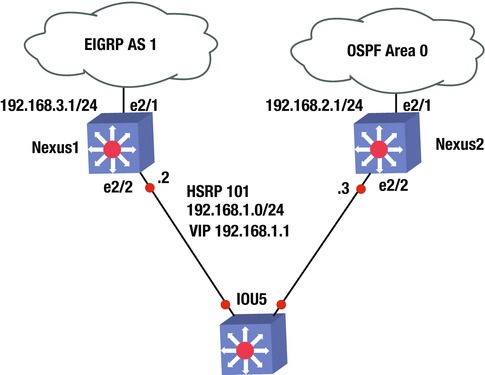
EXERCISE / HSRP, OSPF, AND EIGRP
Using the following diagram to configure HSRP on switches Nexus1 and Nexus2. Nexus1’s connection to the WAN should be configured with EIGRP; whereas Nexus2’s WAN connection should be configured with OSPF. Nexus1 should be configured as the HSRP, but if its WAN interface drops, then Nexus2 should take over as the VIP. OSPF should be configured with the authentication key, Apress. EIGRP should be configured with the authentication key, Apress2. Create VLAN 101 to be a part of HSRP group 101. The HSRP group should be a member of VLAN 101 on both switches.
Nexus1
Interface e2/1: 192.168.3.1
Interface e2/2: VLAN 101: 192.168.1.2

Nexus2
Interface e2/1: 192.168.2.1
Interface e2/2: VLAN 101 192.168.1.3
Exercise Answer
This section provides the answer to the preceding exercise.
Nexus1’s connection to the WAN should be configured with EIGRP, whereas Nexus2’s connection to the WAN should be configured with OSPF. Nexus1 should be configured as the HSRP; but if its WAN interface drops, then Nexus2 should take over as the VIP. OSPF should be configured with authentication key and key chain Apress; EIGRP should be configured with authentication key and key chain Apress2. Create VLAN 101 to be a part of HSRP group 101. The HSRP group should be a member of VLAN 101 on both switches.
Nexus1
Interface e2/1: 192.168.3.1
Interface e2/2: VLAN 101: 192.168.1.2
Nexus2
Interface e2/1: 192.168.2.1
Interface e2/2: VLAN 101 192.168.1.3
Let’s configure the answer. Start with Nexus1. You must first enable features EIGRP, HSRP, and interface-vlan. Next, set the track command to track Nexus1’s WAN interface so that you know if the line-protocol drops. Then create VLAN 101 to assign the IP address and configure the HSRP group 101 under VLAN 101. You assign a priority of 200 to Nexus1; remember that it must be the VIP. The WAN interface that you are tracking must be decremented, allowing Nexus2 to take over as the VIP. Next, create the key chain with key-string Apress2 for EIGRP. Activate the EIGRP process with key chain Apress2 and configure interface e2/1 with the IP address that enables EIGRP for this network. Finally, add the VLAN to interface e2/2.
The following is the Nexus1 configuration.
Nexus1(config)# feature eigrp
Nexus1(config)# feature hsrp
Nexus1(config)# feature interface-vlan
Nexus1(config)# track 1 interface e2/1 line-protocol
Nexus1(config)# int vlan 101
Nexus1(config-if)# ip address 192.168.1.2/24
Nexus1(config-if)# hsrp 101
Nexus1(config-if-hsrp)# priority 200
Nexus1(config-if-hsrp)# preempt
Nexus1(config-if-hsrp)# ip 192.168.1.1
Nexus1(config-if-hsrp)# track 1 decrement 60
Nexus1(config-vlan)# key chain Apress2
Nexus1(config-keychain)# key 1
Nexus1(config-keychain-key)# key-string Apress2
Nexus1(config-keychain-key)# router eigrp 1
Nexus1(config-router)# address-family ipv4 unicast
Nexus1(config-router-af)# authentication mode md5
Nexus1(config-router-af)# authentication key-chain Apress2
Nexus1(config-router-af)# int e2/1
Nexus1(config-if)# ip add 192.168.3.1/24
Nexus1(config-if)# ip router eigrp 1
Nexus1(config-if)# int e2/2
Nexus1(config-if)# switchport
Nexus1(config-if)# switchport access vlan 101
You must first enable features OSPF, HSRP, and interface-vlan. Next, create VLAN 101 to assign the IP address and configure HSRP group 101 under VLAN 101. Assign a priority of 150 to Nexus2, which allows Nexus1 to be the VIP. If the WAN interface drops on Nexus1, the priority becomes 140 and with the preempt command, Nexus2 will take over as the VIP. Then create the key chain with key-string Apress for OSPF. Activate the OSPF process with the key chain Apress1 and configure interface e2/1 with the IP address that enables OSPF for this network. Finally, add the VLAN to interface e2/2.
The following is the Nexus2 configuration.
Nexus2(config)# feature ospf
Nexus2(config)# feature hsrp
Nexus2(config)# feature interface-vlan
Nexus2(config)# int vlan 101
Nexus2(config-if)# ip address 192.168.1.3/24
Nexus2(config-if)# hsrp 101
Nexus2(config-if-hsrp)# priority 150
Nexus2(config-if-hsrp)# preempt
Nexus2(config-if-hsrp)# ip 192.168.1.1
Nexus2(config-if-hsrp)# key chain Apress
Nexus2(config-keychain)# key 1
Nexus2(config-keychain-key)# key-string Apress
Nexus2(config-keychain-key)# router ospf 1
Nexus2(config-router)# area 0 authentication message-digest
Nexus2(config-if)# int e2/1
Nexus2(config-if)# ip add 192.168.2.1/24
Nexus2(config-if)# ip router ospf 1 area 0
Nexus2(config-if)# ip ospf authentication key-chain Apress
Nexus2(config-if)# int e2/2
Nexus2(config-if)# switchport
Nexus2(config-if)# switchport access vlan 101
Summary
This chapter covered the NX-OS operating system that is used in Cisco Nexus switches. The NX-OS is similar to Cisco IOS, but has subtle differences. The chapter discussed these differences, as well as many of the IOS concepts already covered, such as VLANs, VTP, EIGRP, OSPF, BGP, port channels, port profiles, Fabric Extenders, First Hop Redundancy Protocols (HSRP, VRRP and GLBP), virtual device context, virtual port channels, and VRF-lite.