Chapter 4. Classification and Marking
QOS Exam Topics
This chapter covers the following exam topics specific to the QoS exam:
![]() Explain how link layer and network layer markings are used to define service classes and the different applications represented by each of these service classes
Explain how link layer and network layer markings are used to define service classes and the different applications represented by each of these service classes
![]() Given a network and a description of QoS issues, use MQC CLI commands to classify packets
Given a network and a description of QoS issues, use MQC CLI commands to classify packets
![]() Given a network and a description of QoS issues, use class-based marking to assign packets to a specific service class
Given a network and a description of QoS issues, use class-based marking to assign packets to a specific service class
![]() Describe the function of Network Based Application Recognition
Describe the function of Network Based Application Recognition
![]() Describe the purpose of pre-classification to support QoS in various VPN (IPSEC, GRE, L2TP) configurations
Describe the purpose of pre-classification to support QoS in various VPN (IPSEC, GRE, L2TP) configurations
![]() Describe QoS trust boundaries and their significance in LAN based classification and marking
Describe QoS trust boundaries and their significance in LAN based classification and marking
QoS classification tools categorize packets by examining the contents of the frame, cell, and packet headers, whereas marking tools allow the QoS tool to change the packet headers for easier classification. Many QoS tools rely on a classification function to determine to which traffic the tool applies. To place voice and data traffic in separate queues, for example, you must use some form of classification to differentiate the two types of traffic and place the identified traffic in the proper queue. Marking provides a way for QoS tools to change bits in the packet header to indicate the level of service this packet should receive from other QoS tools. For instance, you can use marking tools to change the marking in voice packets to ensure that a classification tool can differentiate a voice packet from a data packet. Without the marking feature, the frame, packet, or cell remains unchanged.
Marking involves placing a value into one of the small number of well-defined frame, packet, or cell header fields specifically designed for QoS marking. By marking a packet, other QoS functions can perform classification based on the marked field inside a header. Marking simplifies the network’s QoS design, it simplifies configuration of other QoS tools, and it reduces the overhead required by each of the other QoS tools to classify the packets.
Although classification and marking tools do not directly affect the bandwidth, delay, jitter, or loss experienced by traffic in the network, classification and marking tools are the building blocks for all other QoS tools. With these tools, all traffic on the network is identified for the next QoS tool to act upon.
The concepts that apply to all classification and marking are covered in the first section of this chapter, including the terminology, fields used, and the meaning behind each of the available marked fields. Following that, this chapter covers several classification and marking tools, with example configurations, as well as show, and debug commands.
The purpose of the “Do I Know This Already?” quiz is to help you decide whether you really need to read the entire chapter. If you already intend to read the entire chapter, you do not necessarily need to answer these questions now.
The 10-question quiz, derived from the major sections in “Foundation Topics” portion of the chapter, helps you determine how to spend your limited study time.
Table 4-1 outlines the major topics discussed in this chapter and the “Do I Know This Already?” quiz questions that correspond to those topics.
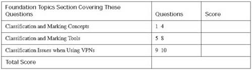
Caution The goal of self-assessment is to gauge your mastery of the topics in this chapter. If you do not know the answer to a question or are only partially sure of the answer, mark this question wrong for purposes of the self-assessment. Giving yourself credit for an answer you correctly guess skews your self-assessment results and might provide you with a false sense of security.
You can find the answers to the “Do I Know This Already?” quiz in Appendix A, “Answers to the ‘Do I Know This Already?’ Quizzes and Q&A Sections.” The suggested choices for your next step are as follows:
![]() 8 or less overall score—Read the entire chapter. This includes the “Foundation Topics,” the “Foundation Summary,” and the “Q&A” sections.
8 or less overall score—Read the entire chapter. This includes the “Foundation Topics,” the “Foundation Summary,” and the “Q&A” sections.
![]() 9 or 10 overall score—If you want more review on these topics, skip to the “Foundation Summary” section and then go to the “Q&A” section. Otherwise, move to the next chapter.
9 or 10 overall score—If you want more review on these topics, skip to the “Foundation Summary” section and then go to the “Q&A” section. Otherwise, move to the next chapter.
|
1. |
Which of the following tools can be used to classify packets generated on behalf of an application that uses static well-known TCP port numbers? a. CB Marking b. ECN c. NBAR d. Pre-classify |
|
2. |
Which of the following tools can be used to classify packets generated on behalf of an application that dynamically allocates the TCP ports numbers used by the application? a. CB Marking b. ECN c. NBAR d. Pre-classify |
|
3. |
Which of the following header fields are part of the IEEE 802.1Q header? a. DE b. User Priority c. QoS d. DSCP e. ToS |
|
4. |
Imagine a PC, connected to an IP phone via an Ethernet cable, with the IP phone connected to a 2950 switch. The switch is cabled to an access router, which in turn has Frame Relay connectivity to the central site. Assuming trunking issued between the IP phone and the switch, where is the recommended trust boundary for data coming from the PC towards the central site? a. PC b. Phone c. Switch d. Access router e. Frame Relay cloud |
|
5. |
Imagine a router configuration with several class-map commands, with a policy map referring to the service classes defined in the class-map commands. The policy map has been enabled for incoming packets on interface Fa0/1. What command would you look for in order to tell if Class Based Marking was in use, as opposed to some other MQC command? a. match b. match-all c. priority d. mark e. set |
|
6. |
Examine the following example of commands typed in configuration mode in order to create a class map. Assuming that the class fred command was used inside a policy map, and the policy map was enabled on an interface, which of the following would be true in regards to packets classified by the class map? Router(config)#class-map fred Router(config)#match ip dscp ef Router(config)#match ip dscp af31 a. Matches packets with both DSCP EF or AF31 b. Matches packets with either DSCP EF or AF31 c. Matches all packets that are neither EF or AF31 d. Matches no packets e. Matches packets with precedence values of 3 and 5 |
|
7. |
Examine the following configuration snippet, and assume that all commands related to the class-map and all interface commands are shown. Which of the following answer best explains why the show command shows that class barney is not matching any packets? class-map dino match protocol rtp audio ! policy-map barney class dino set ip dscp ef ! interface fastethernet0/0 ip address 1.1.1.1 255.255.255.0 service-policy input barney a. There is no RTP audio traffic currently in the network b. You cannot enable CB Marking as an input function c. The show command only works when the mls enable counters interface subcommand is used d. The ip cef global command is required . e. The show policy-map interface fa0/0 command lists configuration information, but not packet counters |
|
8. |
Assume that a router is configured correctly so that voice payload packets are marked with DSCP value EF. Which of the following commands could have been used inside the policy-map to cause CB Marking to set that value? a. set ip dscp ef b. set ip dscp 46 c. set dscp ef d. set dscp 46 e. All of the above f. None of the above |
|
9. |
Router A is the endpoint of an IPSEC VPN tunnel. Packets entering router A before being encrypted into the tunnel have been marked with meaningful DSCP values. What causes router A to copy the ToS byte from the original packet into the new VPN IP header? a. It works automatically, without any commands required b. The ip cef global command is needed c. The mls qos global command is needed d. The qos pre-classify global command is needed e. The qos pre-classify command is needed on the IPSEC crypto map |
|
10. |
Router A is the endpoint of an IPSEC VPN tunnel. Packets entering router A on interface fa 0/0 will be encrypted and then forwarded to a central site out interface S0/0. You want to enable CB Marking on egress packets on the serial0/0 interface, but you want to look at the fields in the IP, TCP, and UDP headers of the original packet, before encryption. What must be done to allow your policy map to work? a. It works automatically, without any commands required b. The ip cef global command is needed c. The mls qos global command is needed d. The qos pre-classify global command is needed e. The qos pre-classify command is needed on the IPSEC crypto map |
The contents of the “Foundation Topics” section of this chapter, and most of the rest of the chapters in this book, follow the same overall flow. Each chapter describes a type of category of QoS tool. Each “Foundation Topics” section begins with coverage of the concepts behind these tools. Then, each tool is examined, with coverage of how each tool works like the other tools, and how it works differently than the other tools. So, most of the core concepts are explained in the first part of the chapter; some of the concepts may be explained in the section about a specific tool, however, particularly if the concepts apply only to that tool.
The second part of the chapter covers class-based marking (CB Marking), Network Based Application Recognition (NBAR), and VPN tunnel pre-classification. For each tool, the pertinent configuration, show, and debug commands are also covered.
Most QoS tools classify traffic, which allows for each class of traffic to receive a different level of treatment from other traffic classes. These different types or classes of traffic are typically called service classes in QoS terminology. Classification allows the devices to decide which packets are part of each service class, which then allows the devices to perform other QoS functions differently based on the service class.
Classification and marking tools not only classify packets into service classes, but they also mark the packets in the same service class with the same value in a field in the header. By marking the packets, other QoS tools that examine the packet later can examine the marked bits to more easily classify packets.
Almost every QoS tool uses classification to some degree. To put one packet into a different queue than another packet, the IOS must somehow differentiate between the two packets. To perform header compression on Real Time Protocol (RTP) packets, but not on other packets, the IOS must determine which packets have RTP headers. To shape data traffic going into a Frame Relay network, so that the voice traffic gets enough bandwidth, the IOS must differentiate between Voice over IP (VoIP) and data packets. If an IOS QoS feature needs to treat two packets differently, it must use classification.
Because most QoS tools need to differentiate between packets, most QoS tools have classification features. In fact, many of you will already know something about several of the QoS tools described in this book, and you will realize that you already know how to perform classification using some of those tools. For instance, many QoS tools enable you to classify using access-control lists (ACLs). If ACL 101 permits a packet, a queuing tool might put the packet into one queue; if ACL 102 permits a packet, it is placed in a second queue; and so on. In one way of thinking, queuing could instead be called classification and queuing, because the queuing feature must somehow decide which packets end up in each queue. Similarly, traffic shaping could be called classification and traffic shaping, policing could be called classification and policing, and so on. Because most QoS tools classify traffic, however, the names of most QoS tools never evolved to mention the classification function of the tool.
Most classification and marking tools, like the other types of QoS tools, generally operate on packets that are entering or exiting an interface. The logic works something like an ACL, but the action is marking, as opposed to allowing or denying (dropping) a packet. More generally, classification and marking logic for ingress packets can be described as follows:
![]() For packets entering an interface, if they match criteria 1, mark a field with a value.
For packets entering an interface, if they match criteria 1, mark a field with a value.
![]() If the packet was not matched, compare it to criteria 2, and then mark a potentially different field with a potentially different value.
If the packet was not matched, compare it to criteria 2, and then mark a potentially different field with a potentially different value.
![]() Keep looking for a match of the packet, until it is matched
Keep looking for a match of the packet, until it is matched
![]() If the packet is not matched, no specific action is taken with the packet, and it is forwarded just like it would have been if no QoS had been configured.
If the packet is not matched, no specific action is taken with the packet, and it is forwarded just like it would have been if no QoS had been configured.
Note This book uses the following terms describe the data structures used when sending data:
![]() Frame—Bits that include the data link layer header and trailer (for example, Ethernet frame and Frame Relay frame)
Frame—Bits that include the data link layer header and trailer (for example, Ethernet frame and Frame Relay frame)
![]() Cell—Specifically, an Asynchronous Transfer Mode (ATM) cell
Cell—Specifically, an Asynchronous Transfer Mode (ATM) cell
![]() Packet—Bits that include the network layer header, but does not include the data link header (for instance, an IP packet)
Packet—Bits that include the network layer header, but does not include the data link header (for instance, an IP packet)
![]() Segment—Bits that include the TCP or UDP header, but not the data link or network layer header
Segment—Bits that include the TCP or UDP header, but not the data link or network layer header
This chapter focuses on Class-Based Marking (CB-Marking). CB Marking can classify packets into service classes by directly examining frame, cell, packet, and segment headers. CB Marking can also refer to access control lists (ACLs) to match packets, with packets permitted by an ACL being considered to match the logic used by CB Marking. For reference, Table 4-2 lists many of the most popular things that can be matched with an IP ACL; Table 4-3 lists the fields directly matchable by CB Marking in router IOS (as of Cisco IOS Software Release 12.2(15)T5):

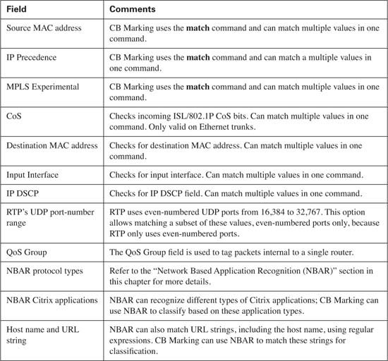
CB Marking can be configured to look at many of the fields in Tables 4-2 and 4-3 to directly classify packets. However, CB Marking can also use NBAR to classify packets. NBAR provides a router with the capability to classify packets, particularly hard-to-identify packets. Independently, NBAR can be configured to keep counters of traffic types and traffic volume for each type.
NBAR classifies packets that are normally difficult to classify. For instance, some applications use dynamic port numbers, so a statically configured match command, looking for a particular UDP or TCP port number, simply could not classify the traffic. NBAR can look past the UDP and TCP header, and refer to the host name, URL, or MIME type in HTTP requests. (This deeper examination of the packet contents is sometimes called deep packet inspection.) NBAR can also look past the TCP and UDP headers to recognize application-specific information. For instance, NBAR allows recognition of different Citrix application types, and allows searching for a portion of a URL string.
You can easily recognize when CB Marking is using NBAR for classification. When the match protocol command is used, CB Marking is looking to match a protocol discovered by NBAR.
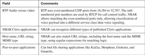
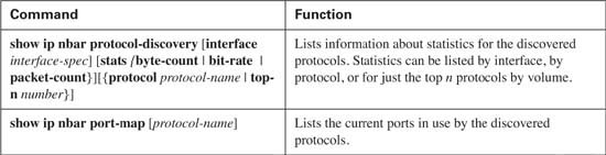
Whether or not NBAR is used with CB Marking, it can be used to gather and report statistics about packets entering and exiting an interface. To see an exhaustive list of protocols, use the show ip nbar protocol-discovery command on a router that has NBAR enabled on one or more interfaces. Because CB Marking can take advantage of NBAR’s powerful packet matching capabilities, you should be aware of some of the more popular and more useful types of packets that NBAR can match. Table 4-4 lists those values.
Note Some documents refer to NBAR’s capability to look past the Layer 4 header as deep packet inspection and subport inspection.
Cisco IOS Software Release 12.2(15)T and later include the Cisco NBAR Protocol Discovery (CNPD) MIB. You can configure NBAR and monitor statistics, including providing the capability for the router to send a trap when user-defined thresholds are crossed. Also, you can configure the NBAR MIB to send traps to the management station when new protocols are discovered on the network, which can be useful for both QoS and for security purposes.
Marking involves setting some bits inside a data link or network layer header, with the goal of letting other devices’ QoS tools classify based on the marked values. You can mark a wide variety of fields, and each has a particular purpose. Some fields are more widely used, and some are less widely used. Some marking options make sense for all devices on the LAN, whereas others only when using specific hardware platforms. Marking at the WAN is possible, too.
The following sections list the header fields that you can use for marking, along with explanations of when it is most useful to use that particular field. Recommendations follow these sections as to when to use classification and marking.
The two most popular marking fields for QoS are the IP Precedence and IP DSCP fields that were introduced in Chapter 2, “QoS Tools and Architectures.” QoS tools frequently use these two fields in part because the IP packet header exists from endpoint to endpoint in a network, as shown in Figure 4-1.
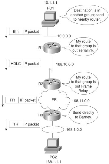
As seen in Figure 4-1, the IP packet en route to host PC2 stays intact throughout the network, whereas the data-link headers only exist while a frame is crossing between a host and a router, or between routers.
Figure 4-2 outlines the two marking fields and their positions inside an IP header.

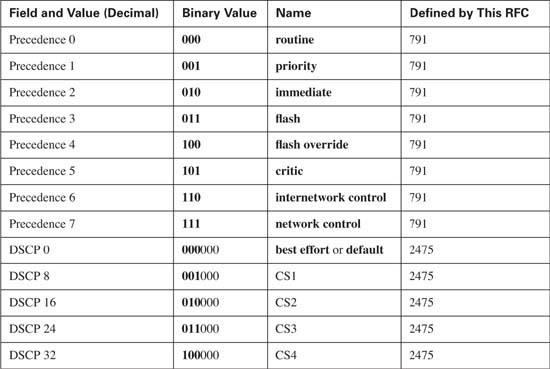
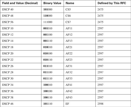
You can mark the Precedence and DSCP fields with any valid binary value of either 3 or 6 bits, respectively. Chapter 2 contains detailed discussion of the recommended values used in these two fields. Briefly, Precedence field values should grow in importance, and in QoS behavior, as the number gets higher. DSCP differs in that several per-hop behavior (PHB) RFCs define suggested DSCP values for which the larger number does not always get a better QoS treatment.
Table 4-5 lists the IP precedence and DSCP values, and their names, for review. Note that not all DSCP values are listed; only the DSCP values suggested by the DiffServ RFCs are listed in the table. Router QoS tools that are capable of setting DSCP can set any of the actual 64 values. (As you will read in Chapter 9, the 2950 cannot set all 64 DSCP values.)
The two IP header QoS marking fields do not provide all the QoS marking fields needed today. One day, all other Layer 3 protocols besides IP may no longer be used. One day, all LAN switches will be capable of looking at IP headers, including IP DSCP and Precedence, and perform QoS based on those fields. Likewise, one day, all WAN services, including Frame Relay and ATM switches, will be able to perform QoS based on these same fields. However, today’s reality is that even as more and more devices become capable of marking and reacting to IP precedence and DSCP, it will be a long time before all networking devices are both capable and configured to use these fields for QoS purposes. So, other QoS marking fields are needed.
Many LAN switches today can mark and react to a Layer 2 3-bit field called the Class of Service (CoS) located inside an Ethernet header. The CoS field only exists inside Ethernet frames when 802.1Q or Inter-Switch Link (ISL) trunking is used. (The IEEE 802.1P standard actually defines the usage of the CoS bits inside the 802.1Q header.) You can use the field to set 8 different binary values, which can be used by the classification features of other QoS tools, just like IP precedence and DSCP. Figure 4-3 shows the general location of the CoS field inside ISL and 802.1P headers.

The term CoS really refers to two different fields—a field inside either the 802.1Q trunking header, or a field inside the ISL header. The IEEE 802.1Q standard uses the 3 most-significant bits of the 2-byte Tag Control field, called the user-priority bits. The Cisco proprietary ISL specification uses the 3 least-significant bits from the 1-byte User field, which is found inside the ISL header’s user field byte. In general conversation, and in the QoS courses from Cisco, the term CoS applies to either of these two fields.
When can CoS be marked, and when can it be useful for classification to a QoS tool? First of all, trunking with 802.1Q or ISL must be enabled before the CoS field even exists! Second, as soon as the packet experiences Layer 3 forwarding, either with a router or some Layer 3 switch, the old LAN header gets discarded—which means you lose the CoS field. After a CoS field has been created and populated with the desired markings, routers and switches have several QoS tools that can react to these markings. Consider, for instance, a typical trunking environment, as shown in Figure 4-4, where all LAN switches are only performing Layer 2 switching.

To mark the CoS bits, trunking must be used—and in Figure 4-4, trunking could be used on every Ethernet segment. Switches typically use trunking on the Ethernet segments to other switches, routers, and to IP Phones. Typically, switches do not need to use trunking on segments connected to PCs or servers. Because some networking cards have the capability to support 802.1Q or ISL trunking, however, servers and PCs can set the CoS bits.
Note Trunking requires a Fast Ethernet interface, or Gigabit, or 10 Gigabit—it is not supported over 10-Mbps Ethernet. This book does not distinguish among the different types of Ethernet upon each mention.
Both routers and switches use QoS tools that can react to the marked CoS bits. Cisco routers can indeed mark CoS bits for frames exiting an Ethernet interface that supports trunking. For instance, R3 could mark CoS 5 on a frame it forwards out its FA 0/0 interface. Other Cisco router QoS tools can react to the marked CoS bits on incoming frames as well. For instance, R3 could mark packets entering its FA0/0 interface with a particular DSCP value based on the incoming CoS value. Later in this chapter, you will see a sample configuration for class-based marking that performs both of these functions.
Cisco switches vary widely regarding their capabilities to set CoS bits and react to previously marked CoS bits. Switches can support marking of CoS, and more often today support marking of IP precedence and DSCP as well. LAN switches that do support QoS features generally perform output queuing, and sometimes input queuing, choosing queues based on CoS values. Congestion avoidance using Weighted Random Early Detection (WRED) is another typical switch QoS feature. In addition, some switches support policing tools, also based on CoS. Chapter 9, “LAN QoS,” covers LAN QoS in additional depth.
You can use single-bit fields in Frame Relay and ATM networks to mark a frame or cell for Layer 2 QoS. Unlike IP precedence, IP DSCP, and 802.1P/ISL CoS, however, these two fields are not intended for general, flexible use. Each of these single-bit fields, when set, imply that the frame or cell is a better candidate to be dropped, as compared with frames or cells that do not have the bit set. In other words, you can mark the bit, but the only expected action by another QoS tool is for the tool to drop the frame or cell.
Frame Relay defines the discard eligibility (DE) bit, and ATM defines the cell loss priority (CLP) bit. The general idea is that when a device, typically a WAN switch, experiences congestion, it needs to discard some frames or cells. If a frame or cell has the DE or CLP bit set, respectively, the switch may choose to discard those frames or cells, and not discard other frames or cells. If the DE or CLP bit is set, there is no requirement that the Frame Relay and ATM switches react to it—just like there is no guarantee that an IP packet with DSCP EF will get special treatment by another router. It’s up to the owner of the Frame Relay or ATM switch to decide whether it will consider the DE and CLP bits, and how to react differently.
You can use two other QoS marking fields in specialized cases. The MPLS Experimental bits comprise a 3-bit field that you can use to map IP precedence into an MPLS label. Also, instead of simply mapping IP precedence to the MPLS Experimental field, you can perform CB Marking at the edge of the MPLS network, classifying on any of the fields mentioned in Tables 4-2, 4-3, and 4-4, and marking the appropriate MPLS experimental bits. This allows MPLS routers to perform QoS features indirectly based on the original IP Precedence field inside the IP packets encapsulated by MPLS, without the need to spend resources to open the IP packet header and examine the IP Precedence field.
Finally, the QoS Group field, an internal marking that exists only within the router, may be set as a packet passes through the fabric of a Cisco gigabit switch router (GSR) or edge services router (ESR). QoS processing can be performed more quickly inside the switching fabric by using the QoS group. Therefore, you may want to configure GSRs and ESRs to mark the QoS group on ingress so that QoS processing occurs more rapidly.
Not all these marked fields receive the same amount of attention on the QoS exams. Refer to the Introduction of this book, and the website suggested there, for the latest information about where to focus your attention. Table 4-6 summarizes the marking fields.

The names of the various marking fields can be confusing. Quality of service (QoS) does not refer to any specific marking field, but it is a term that refers to a broad set of tools that effect bandwidth, delay, jitter, and loss. In other words, this whole book is about QoS. Class of service (CoS) refers to both of the two 3-bit fields in Ethernet trunking headers—one in the ISL header, and one in the 802.1Q trunking header. However, CoS also refers to a 2-bit field inside Systems Network Architecture (SNA) Layer 3 headers, which is also used for QoS functions. Type of service (ToS) is my personal favorite—ToS is the 1-byte field in the IP header, which includes a 3-bit Precedence field, and 4 ToS bits. And of course, DiffServ re-defines the ToS Byte as the DS-byte, with the DSCP field in the first 6 bits. Make sure you remember the true meanings of QoS, CoS, ToS, Precedence, and DSCP.
Classification and marking tools provide many options, but sometimes sorting out the best way to use the tools can be difficult. Classification and marking tools can classify based on a large number of frame and packet header fields. They can also mark a number of fields, the most notable being the IP Precedence and DSCP fields. You can use the classification and marking tools on all routers in the network, on many LAN switches, and even on IP Phones and host computers. This brief section discusses some of the classification and marking design choices.
The first step in making good classification and marking design choices is to choose where to mark. The general rule for choosing where to mark is as follows:
Mark as close to the ingress edge of the network as is possible.
Figure 4-5 diagrams a typical enterprise IP network, which will be used to look more closely at the options for where to mark packets.
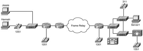
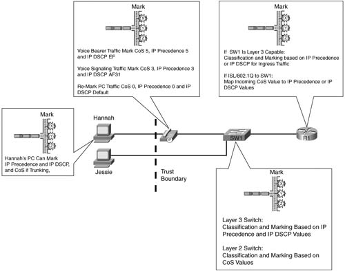
Consider packets that flow left to right in Figure 4-5. The marking efforts for data sent by the PC and phone on the left, up to R1, can be summarized as follows:
![]() Hannah and Jessie, both client PCs, can mark IP precedence and IP DSCP, but it is unlikely that 802.1Q trunking would be used because most end-user Ethernet NICs do not support trunking.
Hannah and Jessie, both client PCs, can mark IP precedence and IP DSCP, but it is unlikely that 802.1Q trunking would be used because most end-user Ethernet NICs do not support trunking.
![]() The IP Phone internally marks its own voice bearer traffic DSCP EF and CoS 5 by default, its own voice signaling traffic DSCP 31 and CoS 3.
The IP Phone internally marks its own voice bearer traffic DSCP EF and CoS 5 by default, its own voice signaling traffic DSCP 31 and CoS 3.
![]() The phone needs to set the CoS value for frames sent to it by the PC, before sending the frame over the trunk to the switch. The switch can be configured to tell the switch to set the CoS to 0, which is typical.
The phone needs to set the CoS value for frames sent to it by the PC, before sending the frame over the trunk to the switch. The switch can be configured to tell the switch to set the CoS to 0, which is typical.
![]() SW1, depending on the type of switch, might be able to re-mark CoS, precedence, or DSCP, or make general (multifield) classification and marking decisions—in other words, it might be able to look at some of the fields listed earlier in Tables 4-2 and 4-3.
SW1, depending on the type of switch, might be able to re-mark CoS, precedence, or DSCP, or make general (multifield) classification and marking decisions—in other words, it might be able to look at some of the fields listed earlier in Tables 4-2 and 4-3.
![]() Finally, R1 can use general multifield classification and marking before sending the packet over the WAN.
Finally, R1 can use general multifield classification and marking before sending the packet over the WAN.
So marking can be done in many places near the ingress edge of the network—but whom do you trust? Classification and marking should not be performed before the frame/packet reaches a trusted device. This location in the network is called the trust boundary. For instance, Jessie formerly marked her packets with DSCP default, but because the user of the PC can change that value, Jessie changed to use DSCP EF to get better service. In most cases, the end-user PCs are beyond the trust boundary. IP Phones can reset CoS, Hannah’s traffic, and rely on the IP phone’s markings with CoS 5, precedence 5, and DSCP EF—with the added benefit that the phone user cannot reset those values. The IP Phone trust settings are controlled by the connected Cisco Catalyst switch, enabling the system administrator to trust markings received from the IP Phone while rewriting the CoS value received from the attached PC.
The final consideration when deciding where to mark involves the function of the various devices, and personal preferences. For instance, IP Phones provide three classes based on CoS—one for voice bearer traffic, one for voice signaling traffic, and one for all packets from the PC. However, a network may need multiple classes for data traffic, so further classification may be required by a switch or router. Some switches provide robust Layer 3 QoS classification and marking functions—in these cases, classification and marking may be performed on the switch; otherwise classification and marking must be performed on the router. (note: the classification and marking features on Cisco LAN switches are covered in chapter 9.) Figure 4-6 shows three typical paths for frames between the end-user device and the first router. The first instance shows a typical installation near the end users—a switch that performs only Layer 2 QoS, and PCs connected to it. Only Layer 2 QoS just means that the switch can react to, or possibly set, CoS, but it cannot react to or mark IP precedence or DSCP. In this case, classification and marking is typically performed as packets enter R1’s Ethernet interface. In addition, because SW1 can support CoS, but not precedence or DSCP, R1 may want to map incoming CoS values to the Precedence or DSCP fields.
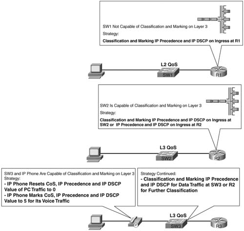
The second part of Figure 4-6 shows a network with a Layer 3 QoS-capable switch. Depending on the type of switch, this switch may not be able to perform Layer 3 switching, but it does have the capability to react to or mark IP precedence or DSCP. In this case, you should classify and mark on the switch. Classification and marking on the Layer 3 switch allows classification and marking closer to the trust boundary of the network, and offers the added benefits of queuing, congestion avoidance, and policing based on the marked values. If only a few sites in the network have Layer 3 QoS-capable switches, you may prefer to perform classification and marking on the router, so all sites’ configurations are similar. However, classifying and marking in the router places additional overhead on the router’s CPU.
Finally, the third example shows a PC cabled through an IP Phone to a Layer 3 QoS-capable switch. The IP Phone can easily take care of classification and marking into two categories—voice and nonvoice. The switch and router can take advantage of those marked values. If more classes are needed for this network’s QoS policy, SW3, or R3, can perform classification and marking. Of course, if the QoS policy for this network only requires the three classes—one for voice bearer traffic, one for voice signaling traffic, one for nonvoice—and all PCs are connected through the switch in the IP Phone, no classification and marking is needed on SW3 or R3!
Figure 4-7 summarizes some of the design options for where to classify and mark, showing the remote site from Figure 4-5.
The choices of where to perform classification and marking can be summarized as follows:
![]() Classify and mark as close to the ingress edge as possible.
Classify and mark as close to the ingress edge as possible.
![]() Consider the trust boundary in the network, making sure to mark or re-mark traffic after it reaches a trusted device in the network
Consider the trust boundary in the network, making sure to mark or re-mark traffic after it reaches a trusted device in the network
![]() Because the two IP QoS marking fields—Precedence and DSCP—are carried end to end, mark one of these fields to maximize the benefits of reducing classification overhead by the other QoS tools enabled in the network.
Because the two IP QoS marking fields—Precedence and DSCP—are carried end to end, mark one of these fields to maximize the benefits of reducing classification overhead by the other QoS tools enabled in the network.
Typically, when the packet makes it to the first WAN router, the initial marking has occurred. However, there may be other instances where marking should take place. Consider Figure 4-8, which shows several additional options for where marking can occur.

Most QoS tools can classify based on IP precedence and DSCP. However, the Frame Relay or ATM switches can also react to the DE and CLP bits, respectively. Therefore, you might want to set DE or CLP for the least-important traffic. If the LAN switches connected to R3 react to CoS settings, but not precedence or DSCP, which is typical of switches that only support Layer 2 QoS, you might want to mark the CoS bits on R3 before sending frames onto the Ethernet.
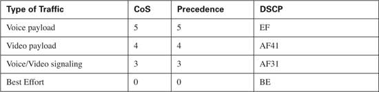
Finally, when you do mark CoS, IP precedence, and IP DSCP, what values should you use? Well, the “bigger is better” attitude is suggested for CoS and precedence. The DiffServ RFCs make recommendations for which markings to use for certain types of traffic, and most current Cisco products (as of publication date) use those recommendations. For instance, the DiffServ RFC’s suggest marking voice signaling traffic as AF31, and Cisco IP Phones indeed do that. Table 4-7 lists these recommended values.
Cisco has also noted some newer, more complete recommendations for Marking DSCP values in packets. These recommendations are spelled out in Cisco’s QoS course, and are based on research from Cisco engineers. It remains to be seen if these settings will become defaults in Cisco products, and if so, how soon they will be included – however, for exam preparation, you should be aware of these values as well. Table 4-8 lists the values.


Also note that Cisco recommends not to use more than 4 or 5 different service classes for data traffic. By using more classes, the difference in behavior between the various classes tends to blur. Also, do not give too many data service classes high priority service, for the same reason.
In summary, classification and marking tools classify packets based on a large number of different fields inside data link and network layer headers. Based on the classification, the tools then mark a field in a frame or packet header, with the goal that other QoS tools can more easily classify and perform specific QoS actions based on these marked fields. Among all the fields that can be marked, IP Precedence and DSCP, because they are part of the IP header, are the only fields that can be marked and carried from end to end in the network.
The second major section of this chapter covers several Classification and Marking tools. First, Class-Based Marking will be covered in detail, followed by NBAR, which can be used by CB Marking to classify packets. Next, the text moves on to an explain some of the issues faced by CB Marking when tunnels are in use, and how IOS can be configured to still classify the packets correctly.
As with the other QoS tools whose names begin with the phrase Class Based, you use MQC commands to configure it. The logic used by CB Marking, now that you know the concepts, it is actually pretty straightforward:
1. Classify packets into service classes using the match command inside an MQC class map.
2. Mark the packets in each service class using the set command inside an MQC policy map.
3. Enable the CB Marking logic, as defined in a policy map, using the MQC service-policy command under an interface.
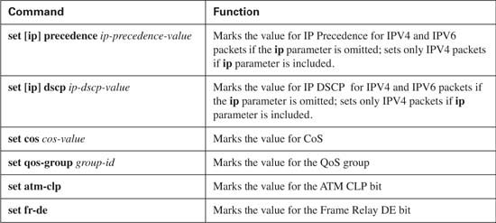
In Chapter 3, you read about the syntax of the MQC commands, and how policy maps use class maps to classify packets. Armed with that knowledge, you now only need to be reminded of all the fields with which you can match packets for classification using the MQC match command, and what fields you can mark with the MQC set command. Table 4-9 lists the options for the match command, which are applicable to all MQC QoS features. Table 4-10 lists the options on the set command, and Table 4-11 lists the show commands related to CB Marking. (Because the options for the match command are the same for all of the other MQC-based QoS tools inside a router, the rest of the chapters will refer back to Table 4-9 instead of repeating this same information in each chapter.)


You should read over the commands presented in the preceding tables to get familiar with the many options. However, you should not have to memorize all the options at this point. If you continue reading the chapters, and practice a little on real lab gear, you should be prepared for answering QoS exam questions.
QoS configuration should follow the process of planning the QoS policies for the network. After those policies have been defined, and the location of where to perform the marking functions has been determined, however, the CB Marking configuration that follows becomes an exercise in deciding how to match or classify the packets, and how to configure the commands correctly. In the first MQC configuration example, for example, the policy has been defined as follows:
![]() All VoIP traffic should be marked with DSCP EF.
All VoIP traffic should be marked with DSCP EF.
![]() All other traffic should be marked with DSCP Default.
All other traffic should be marked with DSCP Default.
Figure 4-9 is used for many example configurations in this book. In the first example, marking is performed for packets entering R3’s FA0/0 interface. In reality, it also makes sense to mark packets near R1 for packet flows from left to right in the figure. To keep the configurations less cluttered, however, only one direction, right to left, is shown. Example 4-1 lists the configuration for this first example.

Example 4-1 CB Marking: Sample 1 Configuration
R3#conf t
Enter configuration commands, one per line. End with CNTL/Z.
R3(config)#ip cef
R3(config)#class-map voip-rtp
R3(config-cmap)#match ip rtp 16384 16383
R3(config-cmap)#policy-map voip-and-be
R3(config-pmap)# class voip-rtp
R3(config-pmap-c)# set ip dscp ef
R3(config-pmap-c)# class class-default
R3(config-pmap-c)# set ip dscp default
R3(config-pmap-c)#interface fa 0/0
R3(config-if)# service-policy input voip-and-be
R3(config-if)#end
R3#
R3#show running-config
Building configuration...
!Portions removed to save space...
ip cef
!
class-map match-all voip-rtp
match ip rtp 16384 16383
!
!
policy-map voip-and-be
class voip-rtp
set dscp ef
class class-default
set dscp default
!
interface Fastethernet0/0
description connected to SW2, where Server1 is connected
ip address 192.168.3.253 255.255.255.0
service-policy input voip-and-be
First, focus on the command prompts in Example 4-1. Note that the class-map command moves the CLI into class map configuration mode, with the prompt R3(config-cmap). The policy-map command moves the CLI into policy map configuration mode, and the class command that follows (not class-map, but just class) moves the CLI into an additional subconfiguration mode that has no specific name.
Note I tend to call configuration mode you are in after using the policy-map command, and then the class command, the policy map class mode when teaching QoS classes.
Next, examine the match commands. The solution could have referred to IP ACL 101 with the match ip access-group 101 command, with ACL 101 matching UDP ports between 16,384 and 32,767, inclusive, to match all VoIP traffic. However, the match ip rtp command matches only the even-numbered ports in this same UDP port range. (VoIP payload only uses the even port numbers.) Therefore, the match ip rtp command is more efficient for matching VoIP, easier to configure, and only matches the VoIP payload.
Continuing down the configuration, examine the policy-map set commands. The first command sets a DSCP of EF for all traffic that matches class-map voip-rtp. The other set command, which follows the class class-default command, sets DSCP of Default for traffic that matches the class-default class-map. In other words, the policy map sets DSCP EF for packets that match one class, and DSCP Default, using the keyword default, for the other class. IOS includes a class that matches all remaining traffic, called class-default, in every policy map. Although the command class class-default was not specified in the configuration, note that the class class-default command is automatically added to the end of a policy map to match all unspecified traffic. class-default was used in the policy map to match all remaining traffic and then mark that traffic as BE.
Note Earlier IOS releases required the keyword ip in the CB Marking set command when setting DSCP—for instance, in the command set ip dscp ef, the ip keyword was required. With IOS 12.2T, the ip keyword is optional. If it is used, IOS removes it from the command when recording the set command in both the running and startup configuration.
Finally, the service-policy command enables CB Marking for ingress packets with the service-policy input voip-and-be interface subcommand. When enabled, IOS applies the policy map classes in the order they appear in the policy-map command. In this example, for instance, the VoIP RTP class is used to examine the packet first; if a match appears, the packet is marked with DSCP EF. After the packet has been matched and marked, it exits the policy map. If no match occurs, only then is the next class, class-default, used to examine the packet.
The next example is a CB Marking configuration that uses the same network as the one used in Example 4-1. R3 is performing the CB Marking function again, but this time R3 expects that SW2 has already set CoS bits to either 0 or 5. The engineers in the meeting to discuss QoS policies for this network decided that SW2 would mark CoS with either 0 or 5, and then R3 would map CoS 0 to DSCP Default, and CoS 5 to DSCP EF. For packets moving left to right, R3 should map DSCP Default back to CoS 0, and DSCP EF back to CoS 5. Figure 4-10 depicts the network and QoS policies, and Example 4-2 lists the configuration.

Example 4-2 CB Marking: Sample 2 Configuration
class-map cos0
match cos 0
!
class-map cos5
match cos 5
!
class-map BE
match ip dscp default
!
class-map EF
match ip dscp EF
!
policy-map map-cos-to-dscp
class cos0
set ip DSCP default
class cos5
set ip DSCP EF
class class-default
set ip dscp default
!
policy-map map-dscp-to-cos
class BE
set cos 0
class EF
set cos 5
class class-default
set cos 0
!
interface FastEthernet0/0
!
interface FastEthernet0/0.1
encapsulation dot1Q 102
service-policy input map-cos-to-dscp
service-policy output map-dscp-to-cos
!
interface FastEthernet0/0.2
encapsulation dot1Q 2 native
As you learned earlier in this chapter, to mark and classify CoS values, a VLAN trunking header must exist on the packet. On R3 in this example, subinterface Fast Ethernet 0/0.1 and subinterface Fast Ethernet 0/0.2 have been created and assigned to the voice VLAN 102 and the data VLAN 2, respectively, using 802.1Q trunking. This configuration creates an 802.1Q header for traffic in the voice VLAN 102, without creating a VLAN header for the data VLAN 2 traffic because VLAN2 will be the native VLAN on this trunk.
The QoS policy required two policy maps in this example. Policy map map-cos-to-dscp matched CoS values for frames entering R3’s FA 0/0.1 interface, and marked DSCP values, for packets flowing right to left in the figure. Therefore, the policy map was enabled on input of R3’s FA 0/0.1 interface. Policy map map-dscp-to-cos matched DSCP values on packets exiting R3’s FA 0/0.1 interface, and marked CoS, for packets flowing left to right in the figure. Therefore, the policy map was enabled on output of R3’s FA 0/0.1 interface. Neither policy map could be applied on the WAN interface, because only interfaces configured for 802.1Q accept service-policy commands that reference policy maps that either classify or mark based on CoS.
Note that you cannot enable a policy map that refers to CoS on interface FA0/0.2 in this example. That subinterface is in the native VLAN, meaning that no 802.1Q header is used. In a real network, you would probably want to enable a policy map on the subinterface in order to mark traffic, but it must classify based on something beside CoS.
CB Marking, and other MQC-based tools, can use NBAR to help classify traffic. By using the match protocol class map subcommand, MQC can match protocols recognized by NBAR. This section describes how to configure CB Marking using NBAR for classification.
The connection between NBAR and CB Marking, or any other MQC tool, is through the match protocol class map subcommand. An MQC tool can include the match protocol command under a class-map command, and as a result, IOS uses NBAR to actually match the packets.
A sample configuration and statistical display may help you make sense of NBAR. Tables 4-12 and 4-13 list the NBAR configuration and exec commands, respectively. Following the tables, Figure 4-11 diagrams the familiar network, where R3 performs CB Marking based on NBAR classification of the URL string. Finally, Example 4-3 lists a sample NBAR and CB Marking configuration, where CB Marking matches a portion of an HTTP URL. The example includes a listing of NBAR statistics gathered on the interface.

Note You can download additional PDLMs from Cisco.com: www.cisco.com/cgi-bin/tablebuild.pl/pdlm
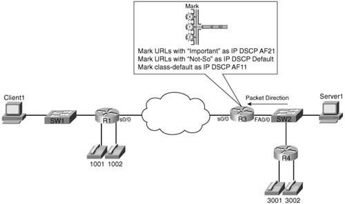
Example 4-3 uses the following criteria for marking packets:
![]() Any HTTP traffic whose URL contains the string “important” anywhere in the URL is marked with AF21.
Any HTTP traffic whose URL contains the string “important” anywhere in the URL is marked with AF21.
![]() Any HTTP traffic whose URL contains the string “not-so” anywhere in the URL is marked with DSCP default.
Any HTTP traffic whose URL contains the string “not-so” anywhere in the URL is marked with DSCP default.
![]() All other traffic is marked with AF11.
All other traffic is marked with AF11.
Example 4-3 shows the configuration.
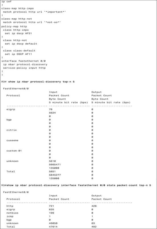
Notice that the class map configuration does not specifically use the term NBAR. Two class maps, http-impo and http-not, use the match command, with the protocol keyword, which implies that the actual classification uses NBAR. NBAR has been enabled on FA0/0 with the ip nbar protocol discovery command, although it is not required for CB Marking to work. Also note that CEF forwarding must be enabled if using NBAR matching inside a policy map. To enable CEF, the ip cef global command is required.
Note In earlier IOS releases, the ip nbar protocol-discovery command was required on an interface before using a service-policy command that used NBAR matching. With 12.2T train releases, the command is no longer required.
NBAR can match URLs exactly, or with some wildcards. You can use the asterisk (*) to match any characters of any length. In this case, as long as the phrases “important” or “not-so” appear in the URL, the packets are matched by one of the two class maps, respectively. Interestingly, when downloading an object with HTTP, the URL does not flow in every packet. When classifying based on URL, NBAR matches all packets beginning with the matched URL until it sees another HTTP request.
Also note that the order of the class commands inside the policy-map is important. Each packet is compared to each class’s matching criteria in order, and once the first match is made, the packet is considered to be in that class. So, the order of the class commands can impact the logic. Also, if many class commands are used, and many packets are not matched until one of the last class commands, the matching process will require more CPU cycles.
When NBAR has been enabled with the ip nbar protocol discovery interface subcommand, the show ip nbar protocol-discovery command lists statistics for NBAR-classified packets. However, just using that command in live networks does not help much, because it lists three lines of output per type of protocol that can be discovered by NBAR—not just the protocols NBAR actually discovered. Therefore, the optional parameters on the command are more useful. For instance, both commands shown in the preceding example use the top-n parameter to limit the output based on the highest-volume protocols. The show command can also limit the statistics for a single interface, or it can limit the statistics to just packet count, or byte count, or bit rate.
Unlike most other IOS features, you can upgrade NBAR without changing to a later IOS version. Cisco uses a feature called packet descriptor language modules (PDLMs) to define new protocols that NBAR should match. When Cisco decides to add one or more new protocols to the list of protocols that NBAR should recognize, it creates and compiles a PDLM. You can then download the PDLM from Cisco, copy it into Flash memory, and add the ip nbar pdlm pdlm- name command to the configuration, where pdlm-name is the name of the PDLM file in Flash memory. NBAR can then classify based on the protocol information from the new PDLM.
CB Marking provides only one show command that provides statistical information: show policy-map interface. The statistics do provide some good insight to the packet volumes being marked by CB Marking. The next sample configuration includes a new configuration and several variations of the show policy-map command.
The same network is used for the next example as was used in the other CB Marking examples, but with different marking criteria. In this case, traffic is generated so that the show command output is more meaningful. The following traffic is generated:
![]() Two G.711 VoIP calls between R4 and R1 using Foreign Exchange Station (FXS) cards on these two routers. Voice Activity Detection (VAD) is disabled.
Two G.711 VoIP calls between R4 and R1 using Foreign Exchange Station (FXS) cards on these two routers. Voice Activity Detection (VAD) is disabled.
![]() One FTP connection from the client PC to the server, with an FTP get of a 40-MB file called big.zip.
One FTP connection from the client PC to the server, with an FTP get of a 40-MB file called big.zip.
![]() One Microsoft NetMeeting video/audio conference between the client and server.
One Microsoft NetMeeting video/audio conference between the client and server.
![]() One web page download from the server to the client. The web page has a few small objects. The web page includes two panes, each with a different JPG file: one called important.jpg; the other called not-so.jpg. The JPGs are exact copies of each other, and each JPG is 687 KB. In later examples, the differing performance of the download of these examples is used to demonstrate the behavior of other QoS tools.
One web page download from the server to the client. The web page has a few small objects. The web page includes two panes, each with a different JPG file: one called important.jpg; the other called not-so.jpg. The JPGs are exact copies of each other, and each JPG is 687 KB. In later examples, the differing performance of the download of these examples is used to demonstrate the behavior of other QoS tools.
Figure 4-12 depicts the same familiar network, and lists the criteria in with the figure for easy reference.

The new criteria for Example 4-4 is as follows:
![]() VoIP payload is marked with DSCP EF.
VoIP payload is marked with DSCP EF.
![]() NetMeeting video traffic is marked with DSCP AF41.
NetMeeting video traffic is marked with DSCP AF41.
![]() Any HTTP traffic whose URL contains the string “important” anywhere in the URL is marked with AF21.
Any HTTP traffic whose URL contains the string “important” anywhere in the URL is marked with AF21.
![]() Any HTTP traffic whose URL contains the string “not-so” anywhere in the URL is marked with AF23.
Any HTTP traffic whose URL contains the string “not-so” anywhere in the URL is marked with AF23.
![]() All other traffic is marked with DSCP Default.
All other traffic is marked with DSCP Default.
Example 4-4 shows the configuration, including the appropriate show commands.
Example 4-4 CB Marking Sample 4, with show Command Output
ip cef
!
class-map voip-rtp
match protocol rtp audio
!
class-map http-impo
match protocol http url "*important*"
!
class-map http-not
match protocol http url "*not-so*"
!
class-map match-any NetMeet
match protocol rtp payload-type 4
match protocol rtp payload-type 34
!
policy-map laundry-list
!
class voip-rtp
set ip dscp EF
!
class NetMeet
set ip dscp AF41
!
class http-impo
set ip dscp AF21
!
class http-not
set ip dscp AF23
!
class class-default
set ip DSCP default
!
interface Fastethernet 0/0
service-policy input laundry-list
end
R3#show policy-map
Policy Map laundry-list
Class voip-rtp
set ip dscp 46
Class NetMeet
set ip dscp 34
Class http-impo
set ip dscp 18
Class http-not
set ip dscp 22
Class class-default
set ip dscp 0
R3#show policy-map laundry-list
Policy Map laundry-list
Class voip-rtp
set ip dscp 46
Class NetMeet
set ip dscp 34
Class http-impo
set ip dscp 18
Class http-not
set ip dscp 22
Class class-default
set ip dscp 0
R3#show policy-map interface fastethernet 0/0 input
Fastethernet0/0
Service-policy input: laundry-list
Class-map: voip-rtp (match-all)
35268 packets, 2609832 bytes
5 minute offered rate 59000 bps, drop rate 0 bps
Match: protocol rtp audio
QoS Set
ip dscp 46
Packets marked 35268
Class-map: NetMeet (match-any)
817 packets, 328768 bytes
5 minute offered rate 19000 bps, drop rate 0 bps
Match: protocol rtp payload-type 4
protocol rtp payload-type 34
QoS Set
ip dscp 34
Packets marked 817
Class-map: http-impo (match-all)
2843 packets, 3462611 bytes
5 minute offered rate 56000 bps, drop rate 0 bps
Match: protocol http url "*important*"
QoS Set
ip dscp 18
Packets marked 2855
Class-map: http-not (match-all)
2828 packets, 3445409 bytes
5 minute offered rate 56000 bps, drop rate 0 bps
QoS Set
ip dscp 22
Packets marked 2842
Class-map: class-default (match-all)
33216 packets, 43649458 bytes
5 minute offered rate 747000 bps, drop rate 0 bps
Match: any
QoS Set
ip dscp 0
Packets marked 33301
Review the configuration before taking a closer look at the show commands. The only part of the configuration that was not covered in the first three examples on CB Marking is the matching of the Microsoft NetMeeting traffic. NetMeeting uses RTP for the video flows, and by default uses G.723 for audio and H.323 for video. To match both the audio and video for NetMeeting, a class map that matches either of the two RTP payload subtypes for G.723 and H.323 is needed. So, the NetMeet class map uses match-any logic, and matches on RTP payload types 4 (G.723) and 34 (H.323).
Note For more background information on RTP payload types, refer to http://www.cisco.com/warp/public/cc/pd/iosw/prodlit/nbarw_wp.htm.
Also note that the NetMeet class map uses a combination of capital letters and lowercase letters, as does the class command that refers to it. Class map names are case sensitive—you may want to choose to use only uppercase or lowercase letters for names to avoid confusion.
The show policy-map laundry-list command just lists a summary of the configuration. You can gather the same information with a show running-config command, but it is summarized nicely with show policy-map. The show policy-map command lists the same configuration information, but it lists the information for all the configured policy maps in this router.
The show policy-map command using the interface option provides statistical information about the number of packets and bytes that have matched each class inside the policy maps. Because CB Marking is configured, it also notes the number of packets that have been marked. You can select all interfaces, just one interface, either input or output, and even select a single class inside a single policy map for display.
Finally, the load-interval interface subcommand can also be useful when looking at any QoS tool’s statistics. The load-interval command defines the time interval over which IOS measures packet and bit rates on an interface. With a lower load interval, the statistics change more quickly; with a larger load interval, the statistics change more slowly. In a lab when you are just learning to use QoS tools, set the load interval to the minimum of 30 seconds, so you can see the results of new traffic, or changes to the configuration, quickly. (The default setting is 5 minutes.)
The examples in this chapter highlight just some of the features of CB Marking, while the list of classification and marking options in Tables 4-9 and 4-10 provides a lot of details. This final section on CB Marking highlights some of the more important small features of CB Marking that so far have only been mentioned as part of the generic commands in Tables 4-9 and 4-10.
The class-map command actually has two optional keywords after the name of the class map, namely match-any and match-all. If you need to refer to multiple match criteria inside a class map, you can use multiple match subcommands. These two keywords can then be used to specify whether all matches must be true (match-all) or if just one needs to be true (match-any). match-all is the default.
The match subcommand under class-map can be used to match up to four IP Precedence values in one command. For instance, match ip precedence 0 1 2 matches packets with any of the three values. Similarly, up to eight DSCP values can be matched with the match ip dscp command, and up to four CoS values can be matched in one match cos command.
Another small but interesting feature is the match not command. Inside a class-map, you can use match not to match all packets that do not match the remaining criteria in the command. For instance, to match packets that are not permitted by ACL 153, you could use the match not access-group 153 command. You could of course just change the ACL to do the opposite of what it was matching originally, but in some cases, it might be more convenient to use match not. For instance, if you might want two classes—one for packets that match ACL 153, and one for those that do not.
All the CB Marking examples in this chapter show a single field being set by a policy map. However, you can actually mark multiple fields in the same policy map for the same packet. For instance, you might want to classify voice payload traffic, and mark it with DSCP EF. However, if the policy map will be enabled for outgoing traffic on a FastEthernet interface that trunks, you might also want to set the CoS field as well. To mark both, you would use two set commands under a single class command. For instance, inside class voice, you might see the commands set ip dscp ef and set cos 5.
If you have a spare router, it’s a good idea to spend some time experimenting and getting familiar with the many options available with CB Marking, particularly with the match and set commands.
Virtual private networks (VPNs) provide a way for Enterprise networks to create a network in which packet contents are kept private, but the packets actually flow over the public Internet. To create a private VPN over a public Internet, VPN hardware or software encapsulates the private IP packets into another IP packet, typically encrypting the original IP packet in order to maintain privacy.
This short section points out a few of the challenges associated with QoS classification in the presence of VPNs.
In the earlier sections of this chapter, you read about the many things that Class-Based Marking can examine in order to classify a packet. However, once a packet has been encapsulated and probably encrypted as part of a VPN, those header fields are no longer available for examination. Figure 4-13 depicts a typical site-to-site VPN environment, using IPSEC tunnels:

Figure 4-13 shows a router at each Enterprise site performing the encapsulation and encryption of the packets. The routers inside the ISP network see an IP header, but it’s not the original IP header. Also, the original IP and TCP header in this example are part of the encrypted payload, making the packet unavailable to routers inside the ISP network. The application headers that NBAR can examine are also encrypted when the packet passes through the ISP. In short, the only thing that the ISP routers can examine are the VPN-created IP headers.
Thankfully, with a good classification and marking strategy, QoS can be extended into the ISP network, even with VPNs in use. When a Cisco router performs the VPN functions, for instance, IPSEC tunnel mode, the router copies the ToS byte from the original IP packet into the newly-created IP header. With proper classification and marking before the packet enters the VPN tunnel, the ISP will at least be able to look at the ToS byte, which includes the DSCP and ECN fields, in order to perform QoS functions. Figure 4-14 depicts the general idea.

Without any overt action or configuration (beyond configuring VPN features as always) IOS copies the ToS byte to the new IP header. That’s true whether using IPSec transport mode, tunnel mode, GRE tunnels, or any of the other Cisco IOS VPN features. So if an enterprise marks a packet with a DSCP value before sending it over a VPN connection, the ISP routers at least have the opportunity to examine the DSCP value to perform QoS functions.
Note IPSec uses either tunnel mode, where the original IP header is encrypted, and transport mode, where the original IP header is not encrypted. With tunnel mode, the original IP ToS byte is copied into the encapsulating IP header; with transport, the original ToS byte is not encrypted, and can be examined by QoS mechanisms. Regardless, the original ToS byte information is referencable by the QoS tools.
VPN tunnel encapsulation and encryption can be done by routers, firewalls, software on a PC, or specialized VPN hardware, like the Cisco 3000 series VPN concentrators. This section of the book looks at a specific implementation issue when performing VPN functions in a Cisco router.
Figure 4-14 depicted the original IP packet being encapsulated, encrypted, and copying the original ToS byte into the new IP header. A router performs these steps after the packet is received, but before the packet is forwarded to the outgoing interface. Once the new VPN packet has been created, the packet is then forwarded to the correct outgoing interface, based on the routing table, and transmitted. As a result, the following general statements can be made:
![]() Packets entering a router interface, not yet in a VPN tunnel, can be processed with ingress QoS features on that interface just like always.
Packets entering a router interface, not yet in a VPN tunnel, can be processed with ingress QoS features on that interface just like always.
![]() Packets exiting a router interface, after encapsulation and encryption by that router into a VPN tunnel, cannot be processed with egress QoS features on that interface just like always. The Egress QoS features can only examine the post-encapsulation IP header.
Packets exiting a router interface, after encapsulation and encryption by that router into a VPN tunnel, cannot be processed with egress QoS features on that interface just like always. The Egress QoS features can only examine the post-encapsulation IP header.
In many cases, these points do not matter a lot. You already know that the DSCP is copied into the new VPN IP header, and effective marking of DSCP before the packet is encapsulated might be all you need to do. However, in some cases, you might want to perform QoS features at egress on some interface, and you might simply want to be able to look at fields inside the original IP packet.
Cisco IOS includes a feature called QoS Pre-classification, just for this specific case. On routers that are VPN endpoints, you can configure the router such that it can refer to the original packet headers for QoS decisions, even seemingly after the original packet has been encapsulated and encrypted.
The QoS Pre-classification feature does allow the router that encapsulates and encrypts the original packet into the tunnel to look at the original headers for QoS functions. This feature does not, however, allow the ensuing routers to be able to look at the original headers—they are indeed encrypted. Internally, in the router performing the encapsulation and encryption, IOS keeps the original unencrypted packet in memory until the QoS actions have been taken.
Figure 4-15 summarizes the behavior of a router in terms of when it can and can’t look at the original headers for QoS features, based on the presence or absence of QoS Pre-classification:

Keep in mind that this feature applies only to the router performing the encapsulation and not other routers. Also, the ToS byte is copied from the original IP header to the encapsulating VPN header automatically as a totally separate and unrelated feature.
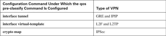
Configuring QoS Pre-classification is relatively simple. First, the command to enable it is qos pre-classify. The only hard part is knowing where to use the command. With IOS, depending on the type of VPN tunnel being created, you might use one of three general styles of configuration. Table 4-14 lists the modes in which you might type the commands, according to the type of VPN configured:

Although the configuration is simple, a few example commands can help. Figure 4-16 shows a sample network, with two remote sites connecting through an ISP. R4 and R1 have been configured such that IPSEC is used when someone at R4’s branch Telnets to R1’s Loopback IP address (10.1.1.1). Figure 4-16 depicts the network, and Example 4-5 that follows shows the configuration on R4, as well as some show commands.

Example 4-5 QoS Pre-classification Commands on R4
!
crypto isakmp policy 2
authentication pre-share
crypto isakmp key cisco address 192.168.2.1
!
!
crypto ipsec transform-set branch ah-md5-hmac esp-des esp-md5-hmac
!
crypto map mccoy 10 ipsec-isakmp
set peer 192.168.2.1
set transform-set branch
match address 150
!
!
match access-group 152
policy-map test-preclass
interface Loopback0
ip address 10.1.4.4 255.255.255.0
!
interface FastEthernet0/0
ip address 192.168.3.4 255.255.255.0
service-policy output test-preclass
load-interval 30
access-list 150 permit tcp any host 10.1.1.1 eq telnet
!
access-list 152 permit tcp any eq telnet any
access-list 152 permit tcp any any eq telnet
R4#clear counters
Clear "show interface" counters on all interfaces [confirm]
R4#
03:07:51: %CLEAR-5-COUNTERS: Clear counter on all interfaces by vty0 (192.168.2.1)
!
R4#show policy-map interface fastEthernet 0/0
FastEthernet0/0
Service-policy output: test-preclass
Class-map: telnet (match-all)
30 second offered rate 1000 bps
Match: access-group 152
Class-map: class-default (match-any)
30 second offered rate 0 bps, drop rate 0 bps
Match: any
R4#show crypto map
Crypto Map "mccoy" 10 ipsec-isakmp
Peer = 192.168.2.1
Extended IP access list 150
access-list 150 permit tcp any host 10.1.1.1 port = 23
Current peer: 192.168.2.1
Security association lifetime: 4608000 kilobytes/3600 seconds
PFS (Y/N): N
Transform sets={
branch,
}
FastEthernet0/0
R4#configure terminal
Enter configuration commands, one per line. End with CNTL/Z.
R4(config)#crypto map mccoy 10 ipsec-isakmp
R4(config-crypto-map)#no qos pre-classify
R4#clear counters
Clear "show interface" counters on all interfaces [confirm]
R4#
03:10:59: %CLEAR-5-COUNTERS: Clear counter on all interfaces by vty0 (192.168.2.1)
!
! (Generated several screens worth of telnet traffic next...
!
R4#show policy-map interface fastEthernet 0/0
FastEthernet0/0
Service-policy output: test-preclass
Class-map: telnet (match-all)
30 second offered rate 0 bps
Match: access-group 152
Class-map: class-default (match-any)
Match: any
R4#show crypto map
Crypto Map "mccoy" 10 ipsec-isakmp
Peer = 192.168.2.1
Extended IP access list 150
access-list 150 permit tcp any host 10.1.1.1 port = 23
Current peer: 192.168.2.1
Security association lifetime: 4608000 kilobytes/3600 seconds
PFS (Y/N): N
Transform sets={
branch,
}
Interfaces using crypto map mccoy:
FastEthernet0/0
!
The example shows a test with qos pre-classify enabled, and then the same example with it disabled. The initial configuration uses IPSEC so that when someone near R4 Telnets to R1’s Loopback IP address (10.1.1.1), IPSec is used to encrypt the packets. The crypto map mccoy global command includes the qos pre-classify subcommand. So, any QoS features that might be enabled on R4’s Fa0/0 interface (the outgoing interface for the traffic) should be able to look at the headers for these IPSEC encrypted packets.
To prove the function, policy-map test-preclass was created and enabled for output packets on R4’s FA0/0 interface. This policy map has a single class called telnet, which matches all Telnet packets. All other types of packets will match the class-default class. (To test, I simply Telnetted to match the crypto map, and did several commands to generate Telnet traffic.) As the output from the show policy-map interface command indicates, the counters in class telnet show packets and bytes as matching that class. The small amount of traffic in class-default was simply overhead traffic.
Next, the example shows the no qos pre-classify subcommand, which removes the pre-classification function from the crypto map. The same test is run, but now notice the counters in class class-default have grown, but nothing has been matched in class telnet, demonstrating that the egress QoS policy map on R4’s FA0/0 interface cannot look at the pre-VPN headers.
Also note the output of the show crypto map command, both with and without qos pre-classify enabled. When enabled, an extra line shows near the end of the output, stating that qos pre-classification is enabled. This line is simply missing if the feature has not been configured.
The “Foundation Summary” is a collection of tables and figures that provide a convenient review of many key concepts in this chapter. For those of you already comfortable with the topics in this chapter, this summary could help you recall a few details. For those of you who just read this chapter, this review should help solidify some key facts. For any of you doing your final prep before the exam, these tables and figures are a convenient way to review the day before the exam.
Table 4-15 shows the list of items that can be matched using the MQC match command, and Table 4-16 lists the fields that can be marked using CB Marking.


Figure 4-17 outlines the two IP marking fields and their positions inside an IP header.
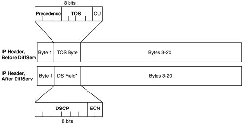
Figure 4-18 shows the general location of the CoS field inside ISL and 802.1P headers.
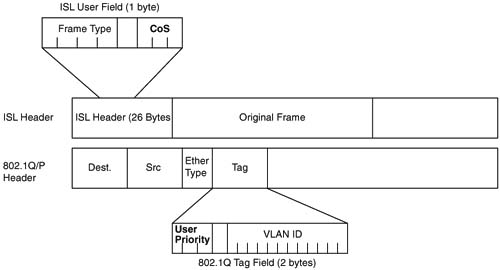
Table 4-17 summarizes the marking fields.

Table 4-18 lists the modes in which you might type the commands, according to the type of VPN configured:
This book attempts to cover the breadth and depth of QoS as covered on the QoS exam (642-642). However, you may want to read more about topics in this chapter, or other classification and marking topics.
For more on the topics in this chapter:
![]() Cisco IOS 12.3 QOS Configuration Guide (http://www.cisco.com/univercd/cc/td/doc/product/software/ios123/123cgcr/qos_vcg.htm)
Cisco IOS 12.3 QOS Configuration Guide (http://www.cisco.com/univercd/cc/td/doc/product/software/ios123/123cgcr/qos_vcg.htm)
For more on other Classification and Marking topics:
![]() For NBAR: http://www.cisco.com/warp/public/cc/pd/iosw/prodlit/nbarw_wp.htm
For NBAR: http://www.cisco.com/warp/public/cc/pd/iosw/prodlit/nbarw_wp.htm
![]() Appendix B, Additional QoS Reference Materials (found on this book’s accompanying CD-ROM):
Appendix B, Additional QoS Reference Materials (found on this book’s accompanying CD-ROM):
— Committed Access Rate (CAR)
— Policy-Based Routing (PBR)
— Dial-Peers
— QoS Policy Propagation Using BGP (QPPB)
For design related guidance:
![]() Cisco’s document “Cisco AVVID Network Infrastructure Enterprise Quality of Service Design” document at http://cisco.com/application/pdf/en/us/guest/netsol/ns17/c649/ccmigration_09186a00800d67ed.pdf
Cisco’s document “Cisco AVVID Network Infrastructure Enterprise Quality of Service Design” document at http://cisco.com/application/pdf/en/us/guest/netsol/ns17/c649/ccmigration_09186a00800d67ed.pdf
As mentioned in the Introduction, you have two choices for review questions. The questions that follow next give you a more difficult challenge than the exam itself by using an open-ended question format. By reviewing now with this more difficult question format, you can exercise your memory better, and prove your conceptual and factual knowledge of this chapter. You can find the answers to these questions in Appendix A.
The second option for practice questions is to use the CD-ROM included with this book. It includes a testing engine and more than 200 multiple-choice questions. You should use this CD-ROM nearer to the end of your preparation, for practice with the actual exam format. You can even customize the CD-ROM exam to include, or not include, the topics that are only on the CCIP QoS.
|
1. |
Describe the difference between classification and marking. |
|
2. |
Describe, in general, how a queuing feature could take advantage of the work performed by a classification and marking feature. |
|
3. |
Characterize what must be true before the CoS field may be useful for marking packets. |
|
4. |
Most other QoS tools, besides classification and marking tools, also have a classification feature. Describe the advantage of classification, in terms of overall QoS design and policies, and explain why classification and marking is useful, in spite of the fact that other tools also classify the traffic. |
|
5. |
Which of the following classification and marking tools can classify based on the contents of an HTTP URL: class-based marking (CB Marking), QoS Pre-classification, network-based application recognition (NBAR), or cos-to-dscp maps? |
|
6. |
Describe the differences between IP extended ACLs as compared with NBAR for matching TCP and UDP port numbers. |
|
7. |
Which of the following QoS marking fields are carried inside an 802.1Q header: QoS, CoS, DE, ToS byte, User Priority, ToS bits, CLP, Precedence, QoS Group, DSCP, MPLS Experimental, or DS? |
|
8. |
Which of the following QoS marking fields are carried inside an IP header: QoS, CoS, DE, ToS byte, User Priority, ToS bits, CLP, Precedence, QoS Group, DSCP, or MPLS Experimental? |
|
9. |
Which of the following QoS marking fields are never marked inside a frame that exits a router: QoS, CoS, DE, ToS byte, User Priority, ToS bits, CLP, Precedence, QoS Group, DSCP, MPLS Experimental, or DS? |
|
10. |
Describe the goal of marking near the edge of a network in light of the meaning of the term “trust boundary.” |
|
11. |
What configuration command lists the classification details when configuring CB Marking? What configuration mode must you use to configure the command? What commands must you issue to place the configuration mode user into that mode? |
|
12. |
What configuration command lists the marking details when configuring CB Marking? What configuration mode must you use to configure the command? What commands must you issue to place the configuration mode user into that mode? |
|
13. |
What configuration command enables CB Marking? What configuration mode must you use to configure the command? What commands must you issue to place the configuration mode user into that mode? |
|
14. |
Describe how you can mark multiple DSCP values with a single class map. How many can you match with a single command? |
|
15. |
What configuration command lets you match RTP audio without also matching RTP video traffic? |
|
16. |
Describe the process by which NBAR can be updated to support new protocols, without upgrading IOS. |
|
17. |
What CB Marking command implies that a policy map requires NBAR in order to match packets? |
|
18. |
What command enables NBAR on an interface for incoming packets? For outgoing packets? |
|
19. |
Describe the reason why you might see multiple set commands inside a single service class in a policy map, and give one example. |
|
20. |
Imagine you are supposed to update a router configuration. The current configuration includes a class-map that refers to ACL 101, which has 23 ACL clauses (separate access-list commands). How could you easily create a new class map that matches the traffic denied by the ACL? |
|
21. |
A router is configred to create a VPN tunnel. Explain the required steps you must take to cause a router to copy the ToS byte of the original packet into the ToS byte of the new IP header used to encapsulate the packet. |
|
22. |
A router is configred to create a VPN tunnel, with unencrypted packets entering interface Fa0/0, and the encrypted packets going over a link to the internet (S0/0). Assuming as many defaults as possible were taken, could a policy map for packets entering the router’s FA0/0 interface examine the packet headers as originally created by the end user device? Why? |
|
23. |
A router is configred to create a VPN tunnel, with unencrypted packets entering interface Fa0/0, and the encrypted packets going over a link to the internet (S0/0). Assuming as many defaults as possible were taken, could a policy map for packets exiting the router’s S0/0 interface examine the packet headers as originally created by the end user device? Why or why not? |
|
24. |
A router is configred to create a VPN tunnel, with unencrypted packets entering interface Fa0/0, and the encrypted packets going over a link to the Internet (S0/0). Assuming the qos pre-classify command was configured correctly, could a policy map for packets entering the router’s FA0/0 interface examine the packet headers as originally created by the end user device? Why or why not? |
|
25. |
Name the three configuration areas in which you might use the qos pre-classify command in order to enable pre-classification. |