Appendix C. Voice Call Admission Control Reference
Suppose that you and a passenger are inside a vehicle traveling on a northbound highway. The highway consists of four regular lanes and one high-occupancy-vehicle (HOV) lane. To gain entry into the HOV lane, your vehicle must contain two or more people. In this instance, the HOV lane represents a priority queue, whereas the remaining four lanes represent lower-priority queues. As traffic begins to build in the four regular lanes, you decide to merge into the HOV lane. Over the next few miles/kilometers, the HOV lane maintains a constant rate of speed while the four regular lanes begin to stall. You are now enjoying the benefits of a priority queue. As you continue traveling northbound, you notice more vehicles, meeting the requirements of two or more passengers, begin to merge into the HOV lane. Over the next few miles/kilometers, your speed decreases until the HOV is now stalled.
In this instance each vehicle in the HOV lane has met the criteria to be placed in the high-priority queue. The expectation is that the HOV lane will move quickly. Contrary to these expectations, as more vehicles enter the HOV lane the slower the lane becomes. How do you prevent this issue from arising?
This scenario illustrates the need to have some mechanism in place to limit the amount of traffic that can gain access into the priority queue, ensuring that a consistent flow of traffic can be maintained across a network link. This concept is called call admission control (CAC), which is the subject of this chapter.
Note For those of you studying for the CCIP QoS 642-641 exam, most of the contents of this chapter are not covered on that exam. The RSVP topics in this chapter are. So, you may want to choose to skip sections of this chapter, and just read the sections covering RSVP. As always, recheck Cisco’s posted exam topics to make sure nothing has changed!
Note This chapter is based on the VoIP Call Admission Control white paper, which can be found at www.cisco.com/en/US/tech/tk652/tk701/technologies_white_paper09186a00800da467.shtml.
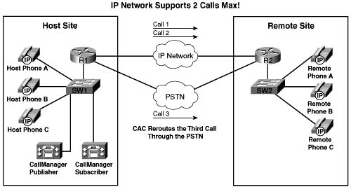
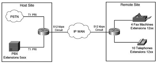
Call admission control (CAC) mechanisms extend the capabilities of other quality of service (QoS) methods to ensure that voice traffic across the network link does not suffer latency, jitter, or packet loss that can be introduced by the addition of other voice traffic. CAC achieves this task by determining whether the required network resources are available to provide suitable QoS for a new call, before the new call is placed. Simply put, CAC protects voice conversations from other voice conversations. Figure C-1 demonstrates the need for CAC. In this example, if the WAN link between the two private branch exchanges (PBXs) has sufficient bandwidth to carry only two Voice over IP (VoIP) calls, admitting the third call will impair the voice quality of all three calls.

Similar to the earlier HOV example, the reason for this impairment is that the employed queuing mechanisms do not provide CAC. If packets exceeding the configured or budgeted rate are received in the priority queue, in this case more than two calls, these packets are just tail dropped from the priority queue. There is no capability in the queuing mechanisms to distinguish which IP packet belongs to which voice call. As mentioned in Chapter 5, “Congestion Management,” both Low Latency Queuing (LLQ) and IP RTP Priority police traffic inside the low-latency queue when the interface is congested, so any packet exceeding the configured rate within a certain period of time is dropped. In this event, all three calls will experience packet loss and jitter, which can be perceived as clipped speech or dropped syllables in each of the voice conversations.
The addition of CAC preserves the quality of the voice conversations in progress by rejecting a new call when insufficient network resources are available to allow the new call to proceed.
If a call has been rejected by a CAC mechanism due to insufficient network resources, there needs to be some alternate route in place to establish the call. In the absence of an alternate route, the caller will hear a reorder tone. The reorder tone is called a fast-busy tone in North America, and is known as overflow tone or equipment busy in other parts of the world. This tone is often intercepted by Public Switched Telephone Network (PSTN) switches or PBXs with an announcement such as “All circuits are busy, please try your call again later.”
Figure C-2 illustrates an originating gateway, router R1, with CAC configured to reroute a call to the PSTN when insufficient network resources are available to route the call over the WAN link.

In a legacy VoIP environment, also known as a toll-bypass environment, the configuration of the originating gateway determines where the call is rerouted. The following scenarios can be configured:
![]() Alternate WAN path—The call can be rerouted to take advantage of an alternate WAN link if such a path exists. This is accomplished by configuring a second VoIP dial peer with a higher preference than the primary VoIP dial peer. When the primary VoIP dial peer rejects the call, the second VoIP dial peer is matched, causing the call to use the alternate WAN link.
Alternate WAN path—The call can be rerouted to take advantage of an alternate WAN link if such a path exists. This is accomplished by configuring a second VoIP dial peer with a higher preference than the primary VoIP dial peer. When the primary VoIP dial peer rejects the call, the second VoIP dial peer is matched, causing the call to use the alternate WAN link.
![]() Alternate PSTN path—The call can be rerouted to take advantage of an alternate time-division multiplexing (TDM) network path if such a path exists. This is accomplished by configuring a plain old telephone service (POTS) dial peer and a physical TDM interface connected to a PSTN circuit or a PBX interface. When the primary VoIP dial peer rejects the call, the POTS dial peer is matched, causing the call to use the alternate PSTN link.
Alternate PSTN path—The call can be rerouted to take advantage of an alternate time-division multiplexing (TDM) network path if such a path exists. This is accomplished by configuring a plain old telephone service (POTS) dial peer and a physical TDM interface connected to a PSTN circuit or a PBX interface. When the primary VoIP dial peer rejects the call, the POTS dial peer is matched, causing the call to use the alternate PSTN link.
![]() Return to originating switch—The call can be returned to the originating TDM switch to leverage any existing rerouting capabilities within the originating switch. How this is accomplished depends on the interface type providing the connectivity between the originating switch and originating gateway:
Return to originating switch—The call can be returned to the originating TDM switch to leverage any existing rerouting capabilities within the originating switch. How this is accomplished depends on the interface type providing the connectivity between the originating switch and originating gateway:
— Common channel signaling (CCS): CCS trunks, such as Primary Rate ISDN (PRI) and Basic Rate ISDN (BRI), separate the signaling and voice conversations into two distinct channels. The signaling channel is referred to as the D channel, and the voice conversation is known as the bearer channel. This separation of channels gives the originating gateway the capability to alert the originating switch in the event that insufficient network resources are available to place the call. This allows the originating switch to tear down the connection and resume handling of the call with an alternate path.
— Channel-associated signaling (CAS): CAS trunks, such as E&M and T1 CAS, combine the signaling and voice conversations in a single channel. The originating gateway has no means of alerting the originating switch if insufficient network resources are available to place the call. For the originating gateway to return the initial call to the originating switch, a second channel must be used to reroute the voice conversation back to the originating switch. This process, known as hairpinning, causes the initial call channel and the second rerouted channel to remain active during the life of the voice conversation.
An IP telephony environment uses much of the same concepts as a legacy VoIP environment to handle CAC. However, an additional layer of control is added by the introduction of the CallManager cluster, which keeps the state of voice gateways and the availability of network resources in a central location. In an IP telephony environment, the configuration of the CallManager cluster in conjunction with the voice gateways determines whether, and where, a call is rerouted in the event of a reject due to insufficient network resources.
Figure C-3 illustrates an IP telephony solution with CAC configured to reroute a call to the PSTN when there is insufficient network resources to route the call over the WAN link.
To successfully implement CAC mechanisms in your packet network, you must begin with a clear understanding of the bandwidth required by each possible call that can be placed. In Chapter 8, “Link Efficiency Tools,” you learned about bandwidth requirements for two of the most popular codecs deployed in converged networks, G.711 and G.729.
The G.711 codec specification carries an uncompressed 64-kbps payload stream, known in the traditional telephony world as pulse code modulation (PCM). G.711 offers toll-quality voice conversations at the cost of bandwidth consumption. The G.711 codec is ideally suited for the situation in which bandwidth is abundant and call quality is the primary driver, such as in LAN environments.
The G.729 codec specification carries a compressed C-kbps payload stream, known in the traditional telephony world as conjugate-structure algebraic-code-excited linear-prediction (CSACELP). G.729 offers a tradeoff: reduced overall bandwidth consumption with a slight reduction in voice quality. G.729 is ideally suited for the situation in which bandwidth is limited, such as in a WAN environment.
As you learned in previous chapters, several other features play a role in determining the bandwidth requirement of a voice call, including header compression, Layer 2 headers, and voice samples per packet. Voice Activation Detection (VAD) can also play a role in the bandwidth required by each call. VAD can be used to reduce the packet payload size by transmitting 2 bytes of payload during silent times rather than the full payload size. For example, the payload on a single G.711 packet using Cisco defaults is 160 bytes. VAD can reduce the size of the payload to 2 bytes during silent times in the conversations. Although VAD can offer bandwidth savings, Cisco recommends that VAD be disabled due to the possible voice-quality issues that it may induce. For the purposes of bandwidth engineering, VAD should not be taken into account.
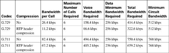
Table C-2 illustrates a few of the possible G.711 and G.729 bandwidth requirements.

*For DQOS test takers: These numbers are extracted from the DQOS course, so you can study those numbers. Note, however, that the numbers in the table and following examples do not include the L2 trailer overhead. Go to www.cisco.com, and search for “QoS SRND” for a document that provides some great background on QoS, and the bandwidth numbers that include data-link overhead.
The formula used to calculate the bandwidth for this combination of factors is as follows:
For example, using G.729 @ 50 pps over Frame Relay without header compression results in the following calculation:
For example, using G.711 @ 50 pps over Ethernet without header compression results in the following calculation:
The elements in the bandwidth per call formula correspond to the following values:
![]() Payload—Payload size per packet depends on the codec selected and the number of voice samples in each packet. One voice sample represents 10 ms of speech. By default, Cisco includes two of these samples in each packet, transmitting 20 ms of speech in each packet. This means that there must be 50 packets per second to maintain a full second of voice conversation, as shown in the following:
Payload—Payload size per packet depends on the codec selected and the number of voice samples in each packet. One voice sample represents 10 ms of speech. By default, Cisco includes two of these samples in each packet, transmitting 20 ms of speech in each packet. This means that there must be 50 packets per second to maintain a full second of voice conversation, as shown in the following:
After the number of samples per packet and packets per second has been determined, the payload size per packet is easily calculated by using the following formula:
Codec @ pps = (Codec payload bandwidth) / (Number of bits in a byte) / (Packets per second)
For example, the following shows a G.711 voice conversation using 50 pps:
G.711 @ 50 pps = 64 kbps / 8 bits / 50 pps = 160 bytes
For example, the following shows a G.711 voice conversation using 33 pps:
G.711 @ 33 pps = 64 kbps / 8 bits / 33 pps = 240 bytes
For example, the following shows a G.729 voice conversation using 50 pps:
G.729 @ 50 pps = 8 kbps / 8 bits / 50 pps = 20 bytes
For example, the following shows a G.729 voice conversation using 33 pps:
G.729 @ 33.334 pps = 8 kbps / 8 bits / 33.334 pps = 30 bytes
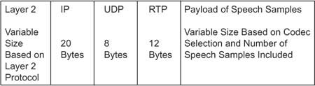
![]() IP/UDP/RTP headers—This is the combination of the IP header, UDP header, and RTP header overhead expressed in bytes. Without compression, this combination equals 40 bytes.
IP/UDP/RTP headers—This is the combination of the IP header, UDP header, and RTP header overhead expressed in bytes. Without compression, this combination equals 40 bytes.
![]() Layer 2 header type—The Layer 2 transport technologies have the following header overheads:
Layer 2 header type—The Layer 2 transport technologies have the following header overheads:
— Ethernet: 14 bytes
— PPP and MLP: 6 bytes
— Frame Relay: 6 bytes
— ATM (AAL5): 5 bytes (plus cell fill waste)
— MLP over Frame Relay: 14 bytes
— MLP over ATM (AAL5): 5 bytes for every ATM cell + 20 bytes for the MLP and AAL5 encapsulation of the IP packet
Figure C-4 illustrates the packet structure of the Layer 2 and IP/UDP/RTP headers and the payload for a voice packet.
![]() 8—Each byte has 8 bits.
8—Each byte has 8 bits.
![]() pps—The number of packets per second required to deliver a full second of a voice conversation. This value depends on the number of 10-ms samples within each packet. By default Cisco includes two 10-ms samples in each packet, transmitting 20 ms of sampled speech in each packet. If the number of samples per packet changes, the packets per second required to deliver a full second of voice conversation changes as well. If the packets per second increase, the overhead associated with the voice conversation increases, which requires additional bandwidth to deliver the same payload. Likewise, if the packets per second decrease, the overhead associated with the voice conversation decreases, which requires less bandwidth to deliver the same payload. The following calculations demonstrate the relationship between the packets per second and the samples included in each packet:
pps—The number of packets per second required to deliver a full second of a voice conversation. This value depends on the number of 10-ms samples within each packet. By default Cisco includes two 10-ms samples in each packet, transmitting 20 ms of sampled speech in each packet. If the number of samples per packet changes, the packets per second required to deliver a full second of voice conversation changes as well. If the packets per second increase, the overhead associated with the voice conversation increases, which requires additional bandwidth to deliver the same payload. Likewise, if the packets per second decrease, the overhead associated with the voice conversation decreases, which requires less bandwidth to deliver the same payload. The following calculations demonstrate the relationship between the packets per second and the samples included in each packet:
— 10 ms * 100 pps = 1 second of voice conversation
— 20 ms * 50 pps = 1 second of voice conversation
— 30 ms * 33 pps = 1 second of voice conversation
Armed with this information you can begin to build out bandwidth requirements based on the network infrastructure, codec, packet payload, and the number of simultaneous calls that need to be supported.
Figure C-5 illustrates a small IP telephony network configured to use the G.711 codec @ 50 pps for all calls placed over the LAN; the G.729 codec @ 50 pps is used for all calls placed over the WAN.

In this example, RTP header compression and VAD are not in use and the Cisco default of 50 packets per second is assumed. A call from Host B phone to Host C phone across the switched LAN infrastructure consumes 85.6 kbps of bandwidth, as shown in the following equation:
A call placed from Host A phone across the WAN infrastructure to Remote A phone in this scenario requires 26.4 kbps, as shown in the following equation:
Assuming that you must allow 6 simultaneous calls across this WAN link at any given time, 158.4 kbps of WAN bandwidth is required to support the voice conversations, as shown in the following equation:
Assuming that you must provide for a guaranteed minimum of 256 kbps for data traffic, the total circuit bandwidth requirements can be derived from the following formula:
or
Examining circuit speeds available today, a 512-kbps link can be used for this IP telephony network to meet the assumed voice and data requirements for 414.4 kbps. The remaining 97.6 kbps can be used for additional overhead, such as routing protocols.
Table C-3 illustrates the relationship between codec, header compression, number of simultaneous calls, and the minimum bandwidth required for data traffic. Although the number of simultaneous calls, packet payload, and data requirements remained constant in this example, the codec selection and header compression varied the total circuit bandwidth requirements significantly.
When you have a clear understanding of the bandwidth required for supporting the addition of voice on your packet network, you can begin to design the proper CAC mechanisms for your converged network.
When a call is placed in a circuit-switched network, a single 64-kbps circuit (DS0) is reserved on each PSTN trunk that the call must traverse to reach the called party and establish the voice conversation. This 64-kbps circuit remains established, without interruption from other voice channels, for the life of the conversation. As voice traffic converges on packet-switched networks, the uninterrupted channel of the circuit-switched network is no longer available. Due to the bursty nature of data traffic, it is difficult to determine whether a packet network has the available resources to carry a voice call at any given moment in time. However, several methods of CAC have been introduced into packet-switched networks in an attempt to provide the same level of call protection enjoyed by a circuit-switched network.
CAC mechanisms in a packet-switched network fall into the following three categories.
![]() Local CAC mechanisms—Local CAC mechanisms base the availability of network resources on local nodal information, such as the state of the outgoing LAN or WAN link. If the interface to the LAN or WAN is inaccessible, there is no need to execute complex decision logic based on the network state, because that network is unreachable and cannot be used to route calls. Local CAC mechanisms also have the capability, through configuration of the local device, to limit the number of voice calls that are allowed to traverse the packet network. If a WAN has enough bandwidth to allow three simultaneous calls without degradation, for instance, local CAC can be used to allow admittance to only the three calls.
Local CAC mechanisms—Local CAC mechanisms base the availability of network resources on local nodal information, such as the state of the outgoing LAN or WAN link. If the interface to the LAN or WAN is inaccessible, there is no need to execute complex decision logic based on the network state, because that network is unreachable and cannot be used to route calls. Local CAC mechanisms also have the capability, through configuration of the local device, to limit the number of voice calls that are allowed to traverse the packet network. If a WAN has enough bandwidth to allow three simultaneous calls without degradation, for instance, local CAC can be used to allow admittance to only the three calls.
![]() Measurement-based CAC mechanisms—Measurement-based CAC techniques look into the packet network to gauge the current state of the network. Unlike local CAC, measurement-based CAC uses a measurement of the packet network’s current state to determine whether a new call should be allowed. Probes sent to the destination IP address and examination of the response for measurement data, such as loss and delay, are used to determine the measurement of the network’s current state.
Measurement-based CAC mechanisms—Measurement-based CAC techniques look into the packet network to gauge the current state of the network. Unlike local CAC, measurement-based CAC uses a measurement of the packet network’s current state to determine whether a new call should be allowed. Probes sent to the destination IP address and examination of the response for measurement data, such as loss and delay, are used to determine the measurement of the network’s current state.
![]() Resource-based CAC mechanisms—Resource-based CAC approaches the issue of protecting voice conversations by first calculating the resources required to establish and protect the call on each leg the call traverses toward the destination. After the required resources have been identified, resource-based CAC attempts to reserve these resources for use by the voice conversation.
Resource-based CAC mechanisms—Resource-based CAC approaches the issue of protecting voice conversations by first calculating the resources required to establish and protect the call on each leg the call traverses toward the destination. After the required resources have been identified, resource-based CAC attempts to reserve these resources for use by the voice conversation.
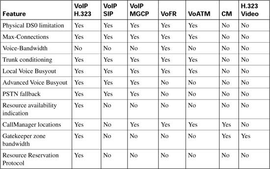
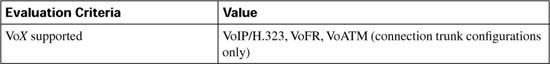
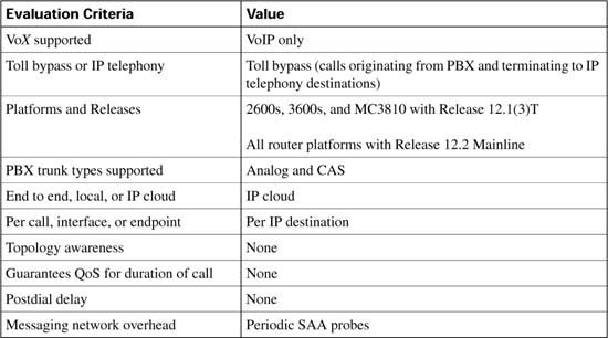
As each CAC method in this chapter is described, it is evaluated against various factors and criteria that will help determine which CAC mechanism is the most appropriate for the network design under consideration. As seen in the wording of the DQOS exam topics, an important part of the DQOS exam includes identifying these CAC tools and their basic features. Table C-4 describes the criteria that is used to evaluate the different CAC tools.


Local CAC mechanisms are the simplest CAC mechanisms to understand and implement. They operate on the originating gateway and consider only the local conditions of that gateway.
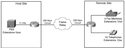
Physical DS0 limitation is a design methodology that limits the number of physical DS0 connections into the gateway. This limitation, in conjunction with other queuing methods, ensures that the gateway can successfully provide IP bandwidth across the WAN for each voice conversation originating from the individual DS0 trunks.
If you have determined that there is 158.4 kbps of WAN bandwidth available to handle 6 simultaneous G.729 calls, for example, DS0 limitations can be implemented by allowing only 6 DS0 connections between the PBX and the originating gateway. These 6 DS0 connections can be in the form of time slots on a digital T1/E1 trunk or individual analog connections, such as FXS, FXO, and E&M trunks.
Figure C-6 shows a network using physical DS0 limitation to provide CAC.

This CAC design method works well in a situation where there is a TDM-to-IP gateway; however, it not effective in an IP telephony environment where a TDM-to-IP conversion does not exist on the WAN router. Calls originated from IP Phones are presented to the WAN router as an IP stream, without a physical TDM interface to provide a DS0 limitation. Another CAC mechanism must be used to solve this issue. Figure C-7 demonstrates this concept.

Restricting physical DS0s on the gateway offers the following advantages:
![]() Adds no extra CPU usage on the gateway or bandwidth overhead to the network
Adds no extra CPU usage on the gateway or bandwidth overhead to the network
![]() Predominant CAC mechanism deployed in toll-bypass networks today
Predominant CAC mechanism deployed in toll-bypass networks today
![]() Protects the quality of voice conversations on the WAN link by limiting the number of voice conversations that are allowed
Protects the quality of voice conversations on the WAN link by limiting the number of voice conversations that are allowed
![]() Offers a known maximum bandwidth consumption rate based on the total number of possible simultaneous calls
Offers a known maximum bandwidth consumption rate based on the total number of possible simultaneous calls
The physical DS0 CAC method has the following limitations:
![]() Not effective for IP telephony applications
Not effective for IP telephony applications
![]() Limited to relatively simple topologies
Limited to relatively simple topologies
![]() Does not react to link failures or changing network conditions
Does not react to link failures or changing network conditions
Table C-5 evaluates the physical DS0 limitation mechanism against the CAC evaluation criteria described earlier in this chapter.

Similar to physical DS0 limitation, Max-Connections uses the concept of limiting the number of simultaneous calls to help protect the quality of voice conversations. Unlike physical DS0 limitation, the max-conn command is a physical gateway configuration applied on a per–dial peer basis.
The first advantage that Max-Connections offers over DS0 limitation is the capability to provision for the oversubscription of TDM interfaces on an originating gateway without compromising the quality of the voice conversations being carried over the WAN. Figure C-8 illustrates a T1 PRI connection from the PSTN and a T1 PRI connection from a PBX. Because a T1 PRI connection has the capability of supporting 23 channels, it is theoretically possible to have 46 simultaneous voice conversations on the host site router that are attempting to traverse the WAN to reach endpoints in the remote site.
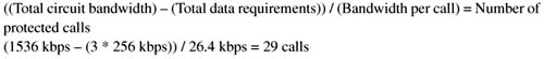
In this example, nine concurrent calls can be supported. Assuming that the data requirement for the IP WAN circuit is 256 kbps, and the codec in use is G.729 at 50 pps without the use of VAD or header compression, the maximum number of calls that can be successfully supported and protected across the 512-kbps WAN link is 9, as shown in the following:
or
Note This calculation does not take into account the bandwidth required for routing updates. Instead, this calculation shows the theoretical maximum number of calls that can traverse this link assuming no packets other than the listed data requirements are present on the link.
If the theoretical maximum of 46 calls over the 2 PRIs is attempted, voice quality for each conversation will suffer greatly, because the current bandwidth of the WAN can provide for a total of 9 simultaneous calls without voice-quality degradation. Example C-1 shows how you can configure the max-conn command on the host site router to limit the number of simultaneous calls on the VoIP dial peer to 9. For this example, assume that all endpoints in the remote site have a directory number consisting of 4 digits, and each directory number begins with the number 12 followed by 2 additional digits.
Example C-1 Max-Connections Host Site Router
!Sets the maximum number of connections (active admission control).
ip precedence 5
session target ipv4:10.1.1.2
Assume that all endpoints in the host site have a directory number consisting of 4 digits and each directory number begins with the number 5 followed by 3 additional digits. Example C-2 shows how you can configure the max-conn command on the remote site router to limit the number of simultaneous calls on the VoIP dial peer to 9.
Example C-2 Max-Connections Remote Site
!Sets the maximum number of connections (active admission control).
ip precedence 5
session target ipv4:10.1.1.1
The second advantage that Max-Connections offers over DS0 limitation is the capability to limit the number of calls that will be allowed to traverse an IP WAN between multiple sites. Because the max-conn command is applied on a per–dial peer basis, a clear understanding of the call volume desired and the available bandwidth between sites must be achieved. To limit the total number of aggregate voice conversations allowed to traverse the WAN link, the max-conn command must exist on each VoIP dial peer. The aggregate of these configurations must not exceed the bandwidth provisioned for the call volume.
Suppose, for example, that the two additional remote sites are added to the preceding example, each with the same data requirements of 256 kbps. In this scenario, 9 simultaneous calls can be protected from each remote site, as shown in the following:
or
The total circuit bandwidth for the host site is increased to a full T1 to handle the two additional sites, as shown in the following:
Note These calculations do not take into account the bandwidth required for routing updates. Instead, this calculation shows the theoretical maximum number of calls that can traverse these links assuming no packets other than the listed data requirements are present on the link.
Figure C-9 illustrates this multiple-site converged network.
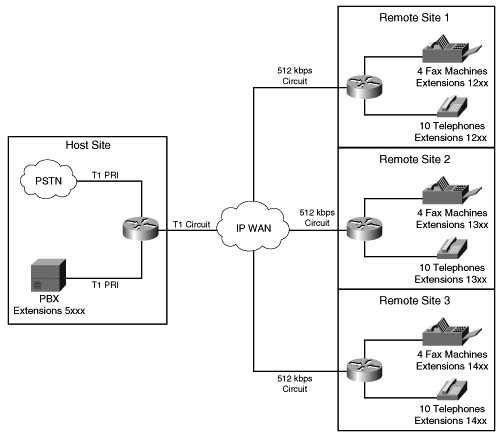
Suppose that endpoints in all remote sites have a directory number consisting of 4 digits, and each directory number at Remote Site 1 begins with the number 12 followed by 2 additional digits. Directory numbers at Remote Site 2 begin with the number 13 followed by 2 additional digits. Directory numbers at Remote Site 3 begin with the number 14 followed by 2 additional digits. Example C-3 shows how you can configure the max-conn command on the host site router to limit the number of simultaneous calls per location on the VoIP dial peer to 9 with an aggregate maximum of 27 calls allowed across the IP WAN.
Example C-3 Max-Connections Host Site Router per Site
! 9 calls allowed on VoIP Dial Peer to Remote Site 1
ip precedence 5
session target ipv4:10.1.1.2
!
dial-peer voice 2 voip
! 9 calls allowed on VoIP Dial Peer to Remote Site 2
ip precedence 5
session target ipv4:10.1.2.2
!
dial-peer voice 3 voip
! 9 calls allowed on VoIP Dial Peer to Remote Site 1
ip precedence 5
session target ipv4:10.1.3.2
Assume that all endpoints in the host site have a directory number consisting of 4 digits, and each directory number begins with the number 5 followed by 3 additional digits. Example C-4 shows how you can configure the max-conn command each remote site router to limit the number of simultaneous calls on the VoIP dial peer to 9, with an aggregate maximum of 27 calls allowed across the IP WAN.
Example C-4 Max-Connections Remote Site 1
!VoIP Dial Peer from Remote Site 1 to Host Site
ip precedence 5
session target ipv4:10.1.1.1
Example C-5 shows the configuration of the max-conn command at Remote Site 2.
Example C-5 Max-Connections Remote Site 2
!VoIP Dial Peer from Remote Site 2 to Host Site
ip precedence 5
session target ipv4:10.1.2.1
Example C-6 shows the configuration of the max-conn command at Remote Site 3.
Example C-6 Max-Connections Remote Site 3
!VoIP Dial Peer from Remote Site 3 to Host Site
ip precedence 5
session target ipv4:10.1.3.1
!
After the maximum number of calls specified by the max-conn command has been reached, another mechanism must be used to connect the call via an alternate route. This is achieved by configuring a second dial peer with the same destination pattern, but with a higher preference. Remember that the dial peer with the lowest preference, that can route the call, will be matched.
Example C-7 shows the configuration of an alternate path using the max-conn command. In this example, dial-peer voice 1 voip is defined with a preference of 1 and dial-peer voice 100 pots is defined with a preference of 2. This indicates that dial peer 1 is preferred over dial peer 100. The two dial peers share the same destination-pattern, meaning that they will both match any dialed digits beginning with 12; however, they will attempt to connect the call using different paths. Dial peer 1 will attempt to connect the call over the IP network sending the dialed digits, whereas dial peer 100 will prefix the digits 91404555 to the dialed digits and attempt to connect the call using the PSTN. Dial peer 1 will connect calls until the number of active calls reaches the configured max-conn of 9. When this maximum has been reached, dial peer 1 can no longer connect calls. At this point, dial peer 100 will begin to connect calls using the alternate path to the PSTN.
Example C-7 Max-Connections Alternate Path
preference 1
ip precedence 5
session target ipv4:10.1.1.2
!
dial-peer voice 100 pots
direct-inward-dial
port 0:D
!Adds prefix 91404555 in front of the called number before sending the digits to the PSTN
prefix 91404555
Max-Connections also offer the capability to limit the number of calls allowed on a POTS dial peer by making the value of the max-conn command for that POTS dial peer lower than the physical number of time slots that are available on a T1/E1 connection between the PSTN or a PBX and an originating gateway.
Although the Max-Connections feature is useful in many scenarios, it has the following drawbacks:
![]() Although it provides some protection for the voice gateway egress WAN link, it provides little or no protection for links in the network backbone.
Although it provides some protection for the voice gateway egress WAN link, it provides little or no protection for links in the network backbone.
![]() It does not work for IP telephony applications that do not use dial peers.
It does not work for IP telephony applications that do not use dial peers.
![]() It is limited to simple topologies.
It is limited to simple topologies.
![]() It does not react to link failures or changing network conditions.
It does not react to link failures or changing network conditions.
Table C-6 evaluates the Max-Connections mechanism against the CAC evaluation criteria described earlier in this chapter.

In a Voice over Frame Relay (VoFR) network, the frame-relay voice-bandwidth command is used in a Frame Relay map class to set aside the bandwidth required to successfully transport the desired number of calls. This method of bandwidth provisioning operates in much the same way as IP RTP Priority and Low Latency Queuing features that reserve bandwidth for traffic flows. Unlike LLQ or RTP Priority, the frame-relay voice-bandwidth command has the capability to provide CAC. Because VoFR operates at Layer 2, Frame Relay headers can be examined to determine whether a frame is carrying voice payload or data payload. The channel identification (CID) in the voice frames is used to identify which individual frames belong with the current voice conversations in progress. Because the frame-relay voice-bandwidth command sets aside a maximum bandwidth for voice conversation, and tracks the number of conversations in progress, the frame-relay voice-bandwidth command has the capability to deny the admission of an additional conversation if the maximum bandwidth allocated to voice will be exceeded.
This CAC feature only applies when VoFR is used, as defined in Frame Relay Forum Implementation Agreement FRF 11. VoFR does not use IP, UDP, and RTP to encapsulate the voice traffic. By eliminating the need for IP and RTP/UDP headers, VoFR reduces the amount of overhead needed to transport the voice payload, as show in the following formula:
For example, a G.729 call using 50 pps requires 10.4 kbps, as shown in the following calculation:
For example, a G.711 call using 50 pps requires 69.6 kbps, as shown in the following calculation:
Figure C-10 shows a host site connected to a remote site via a Frame Relay network. Assume that VoFR was selected to carry the voice payload and 6 simultaneous calls, using G.729 codec with 50 pps, are required to be successfully transported and protected.
The bandwidth required to successfully support and protect six simultaneous calls is determined by the following formula:
In the case of the network in Figure C-10, the following bandwidth is required:
After the bandwidth requirements have been determined, the requirement can be applied to the VoFR map class to establish voice conversations. If the bandwidth requirements are not applied to the VoFR map class, the Voice-Bandwidth size defaults to 0, resulting in CAC rejects for all call attempts because of insufficient bandwidth.
Example C-8 demonstrates how CAC for VoFR is configured by provisioning 64 kbps to transport and protect voice conversations across the Frame Relay network.
You can implement this CAC method only if VoFR is a viable technology in your network.
Example C-8 Frame Relay Voice Bandwidth
encapsulation frame-relay
no fair-queue
frame-relay traffic-shaping
!
interface Serial0/0.1 point-to-point
frame-relay interface-dlci 100
class vofr
!
map-class frame vofr
frame cir 256000
frame bc 2560
frame fragment 320
frame fair-queue
frame-relay voice-bandwidth 64000
Table C-7 evaluates the VoFR Voice-Bandwidth mechanism against the CAC evaluation criteria described earlier in this chapter.

Cisco IOS supports a function called a permanent trunk connection, sometimes called a connection trunk. A connection trunk creates a permanent trunk connection across the VoIP part of the network. To accomplish this, the connection trunk command is configured on a voice port to emulate a permanent connection across a packet network. The bandwidth required by the connection trunk is allocated at the creation of the trunk and remains reserved until the trunk is torn down. Figure C-11 illustrates this concept.
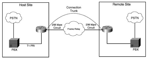
Trunk conditioning is used to monitor the connection trunk state. If the connection trunk becomes unavailable, the originating gateway has the capability to signal the origination PBX and indicate that an alternate route must be found.
A unique attribute of trunk conditioning, compared to other CAC features, is that trunk conditioning has visibility into the condition of the POTS connection on the terminating side of the network and the condition of the WAN. In Figure C-11, if there is a failure in either the WAN or the remote-side TDM connection, the originating gateway can detect this and signal the origination PBX, indicating that an alternate route must be found. This information is carried as part of the keepalive messages that are generated on connection trunk configurations.
You can tune the precise bit pattern that will be generated to the originating PBX. The ABCD bits can be configured to specific busy or out-of-service (OOS) indications that the originating PBX will recognize and act upon.
Trunk conditioning is therefore not a call-by-call feature, as are those discussed so far. It is a PBX trunk busy-back (or OOS) feature. If there is a failure in the WAN, the trunk to the originating PBX is taken out of service so that no calls can be made across that trunk until the WAN connectivity is recovered.
The following example demonstrates how a connection trunk is configured between the host and remote sites. Example C-9 shows the configuration of the master for the trunk.
Example C-9 Connection Trunk Host Site
framing esf
linecode b8zs
ds0-group 2 timeslots 2 type e & m-wink-start
!--- The ds0-group command creates the logical voice-ports:
!--- voice-port 1/0:1 and voice-port 1/0:2.
!
voice-port 1/0:1
!This starts the Trunk connection using digits 2000 to match
!a VoIP dial-peer. The digits are generated internally by the
!router and are not received from the voice-port.
!
voice-port 1/0:2
dial-peer voice 100 voip
destination-pattern 200.
!matches connection trunk string 2000 and 2001
dtmf-relay h245-alphanumeric
session target ipv4:10.1.1.2
ip qos dscp cs5 media
!
dial-peer voice 1 pots
destination-pattern 1000
port 1/0:1
!This dial-peer maps to the remote site's voice-port 1/0:1.
!
dial-peer voice 2 pots
destination-pattern 1001
port 1/0:2
!This dial-peer maps to the remote site's voice-port 1/0:2.
!
interface Serial0/1
ip address 10.1.1.1 255.255.255.0
Example C-10 shows the configuration of the slave for the trunk.
Trunk conditioning is limited in scope because it applies to connection trunk networks only.
Example C-10 Connection Trunk Host Site
framing esf
linecode b8zs
ds0-group 2 timeslots 2 type e & m-wink-start
!
voice-port 1/0:1
!The answer-mode specifies that the router should not attempt to
!initiate a trunk connection, but should wait for an incoming call
!before establishing the trunk.
!
voice-port 1/0:2
dial-peer voice 1 voip
destination-pattern 100.
dtmf-relay h245-alphanumeric
session target ipv4:10.1.1.1
ip qos dscp cs5 media
!
dial-peer voice 2 pots
destination-pattern 2000
port 1/0:1
!This dial-peer terminates the connection from the host site's voice-port 1/0:1.
!
dial-peer voice 3 pots
destination-pattern 2001
port 1/0:2
!This dial-peer terminates the connection from the host site's voice-port 1/0:2.
!
interface Serial0/1
ip address 10.1.1.2 255.255.255.0
clockrate 128000
Table C-8 evaluates the trunk conditioning mechanism against the CAC evaluation criteria described earlier in this chapter.

Several CAC mechanisms generate a busy signal to the originating PBX to indicate that an alternate route must be found to successfully place a call. The preceding section discussed trunk conditioning, which operates on connection trunk networks only. Similar functionality is needed for switched networks. Local Voice Busy-Out (LVBO) is the first of two features that achieve this.
LVBO enables you to take a PBX trunk connection to the attached gateway completely out of service when WAN conditions are considered unsuitable to carry voice traffic. This technique has the following advantages:
![]() With the trunk out of service, each call will not be rejected individually and incur a postdial delay.
With the trunk out of service, each call will not be rejected individually and incur a postdial delay.
![]() Prevents the need for hairpinning-rejected calls back to the originating PBX, using up multiple DS0 slots for a single call.
Prevents the need for hairpinning-rejected calls back to the originating PBX, using up multiple DS0 slots for a single call.
![]() Works well to redirect rejected calls with PBXs that either do not have the intelligence or are not configured appropriately.
Works well to redirect rejected calls with PBXs that either do not have the intelligence or are not configured appropriately.
![]() Prevents a third DS0 on the same T1/E1 circuit from accepting the original call if the call is hairpinned back to the gateway from the originating PBX. This condition is referred to as tromboning.
Prevents a third DS0 on the same T1/E1 circuit from accepting the original call if the call is hairpinned back to the gateway from the originating PBX. This condition is referred to as tromboning.
LVBO provides the originating gateway with the capability to monitor the state of various network interfaces, both LAN and WAN, and signal the originating PBX to use an alternate route should any of the monitored links fail. If any or all of the interfaces change state, the gateway can be configured to busy-back the trunk to the PBX. The reason this feature is called Local VBO is because only local links can be monitored. This feature has no visibility into the network beyond the link of the local gateway.
LVBO in current software works on CAS and analog PBX/PSTN trunks only. On CCS trunks, the cause code functionality can be used to inform the PBX switch to redirect a rejected call. LVBO can be configured in one of two ways:
![]() To force individual voice ports into the busyout state
To force individual voice ports into the busyout state
![]() To force an entire T1/E1 trunk into the busyout state
To force an entire T1/E1 trunk into the busyout state
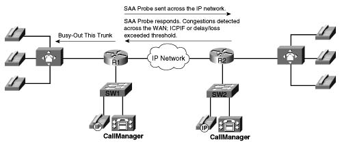
Figure C-12 illustrates the operation of the LVBO feature, and Example C-11 shows the configuration necessary. In the example, the originating gateway is monitoring two interfaces, Ethernet interface e0/1 and WAN interface s0/1, on behalf of voice port 2/0:1, which is a T1 CAS trunk connected to a PBX. As shown in Figure C-12, this feature is only applicable if the origination device is a PBX/ PSTN interface, although the destination device can be anything, including an IP-capable voice device.

Example C-11 Local Voice Busyout
ds0-group 1 timeslot 1-4 type e&m-wink-start
Voice-port 2/0:1
busyout monitor serial0/1
busyout monitor ethernet0/1
The following limitations apply to the LVBO feature:
![]() It has local visibility only in current software (Cisco IOS Release 12.2); it monitors only Ethernet LAN interfaces (not Fast Ethernet), serial interfaces, and ATM interfaces.
It has local visibility only in current software (Cisco IOS Release 12.2); it monitors only Ethernet LAN interfaces (not Fast Ethernet), serial interfaces, and ATM interfaces.
![]() It applies only to analog and CAS trunk types.
It applies only to analog and CAS trunk types.
Table C-9 evaluates the LVBO mechanism against the CAC evaluation criteria described earlier in this chapter.

This section focuses on the following measurement-based CAC techniques:
![]() Advanced Voice Busyout (AVBO)
Advanced Voice Busyout (AVBO)
![]() PSTN fallback
PSTN fallback
These are the first of two types of CAC mechanisms that add visibility into the network itself, in addition to providing local information on the originating gateway as discussed in the preceding sections.
Before we discuss the actual features within this category, some background information on service assurance agent (SAA) probes is necessary, because this is the underlying technique used by the measurement-based CAC methods. SAA probes traverse the network to a given IP destination and measure the loss and delay characteristics of the network along the path traveled. These values are returned to the originating gateway to use in making a decision on the condition of the network and its capability to carry a voice call.
Note the following attributes of measurement-based CAC mechanisms that are derived from their use of SAA probes:
![]() Because an SAA probe is an IP packet traveling to an IP destination, all measurement-based CAC techniques apply to VoIP only (including VoIP over Frame Relay and VoIP over ATM networks).
Because an SAA probe is an IP packet traveling to an IP destination, all measurement-based CAC techniques apply to VoIP only (including VoIP over Frame Relay and VoIP over ATM networks).
![]() As probes are sent into the network, a certain amount of overhead traffic is produced in gathering the information needed for CAC.
As probes are sent into the network, a certain amount of overhead traffic is produced in gathering the information needed for CAC.
![]() If the CAC decision for a call must await a probe to be dispatched and returned, some small additional postdial delay occurs for the call. This should be insignificant in a properly designed network.
If the CAC decision for a call must await a probe to be dispatched and returned, some small additional postdial delay occurs for the call. This should be insignificant in a properly designed network.
SAA is a generic network management feature that provides a mechanism for network congestion analysis, providing analysis for a multitude of other Cisco IOS features. It was not implemented for the purpose of accomplishing CAC, nor is it a part of the CAC suite. But its capabilities to measure network delay and packet loss are useful as building blocks on which to base CAC features.
Note The SAA feature was called response time responder (RTR) in earlier releases of Cisco IOS Software.
SAA probes are similar in concept to the popular ping IP connectivity mechanism, but are far more sophisticated. SAA packets can be built and customized to mimic the type of traffic for which they are measuring the network, in this case a voice packet. A ping packet is almost by definition a best-effort packet, and even if the IP precedence is set, it does not resemble a voice packet in size or protocol. Nor will the QoS mechanisms deployed in the network classify and treat a ping packet as a voice packet. The delay and loss experienced by a ping is therefore a very crude worst-case measure of the treatment a voice packet might be subject to while traversing the very same network. With the penetration of sophisticated QoS mechanisms in network backbones, a ping becomes unusable as a practical indication of the capability of the network to carry voice.
The SAA service is a client/server service defined on TCP or UDP. The client builds and sends the probe, and the server (previously the RTR responder) returns the probe to the sender. The SAA probes used for CAC go out randomly on ports selected from within the top end of the audio UDP-defined port range (16384 to 32767); they use a packet size based on the codec the call will use. IP precedence can be set if desired, and a full RTP/UDP/IP header is used like the header a real voice packet would carry. By default the SAA probe uses the RTCP port (the odd RTP port number), but it can also be configured to use the RTP media port (the even RTP port number) if desired.
SAA was introduced on selected platforms in Cisco IOS Release 12.0(7)T. With the release of 12.2 Mainline IOS, all router platforms support SAA; however, the IP Phones do not currently support SAA probes or respond to SAA probes.
The ITU standardizes network transmission impairments in ITU G.113. This standard defines the term calculated planning impairment factor (ICPIF), which is a calculation based on network delay and packet loss figures. ICPIF yields a single value that can be used as a gauge of network impairment.
ITU G.113 provides the following interpretations of specific ICPIF values:
![]() 5: Very good
5: Very good
![]() 10: Good
10: Good
![]() 20: Adequate
20: Adequate
![]() 30: Limiting case
30: Limiting case
![]() 45: Exceptional limiting case
45: Exceptional limiting case
![]() 55: Customers likely to react strongly
55: Customers likely to react strongly
SAA probe delay and loss information is used in calculating an ICPIF value that is then used as a threshold for CAC decisions, based either on the ITU interpretation described or on the requirements of an individual customer network.
AVBO is an enhancement to LVBO. Whereas LVBO provides for busyout based on local conditions of the originating gateway, AVBO adds the capability to trigger an SAA probe to one or more configured IP destinations. The information returned by the probe, which can be either the explicit loss and delay values, or the ICPIF congestion threshold, is used to trigger a busyout of the TDM trunk connection to the PBX.
AVBO therefore introduces the capability to busy out a PBX trunk, or individual voice ports, based on the current conditions of the IP network. Figure C-13 illustrates this capability.
Example C-12 shows a sample configuration of AVBO on a T1 CAS trunk connected to a PBX.
Example C-12 Advanced Voice Busyout
ds0-group 1 timeslots 1-4 type e&m-immediate-start
!
voice-port 2/0:1
voice-class busyout 4
!
voice class busyout 4
busyout monitor Serial0/1
busyout monitor Ethernet0/1
When using AVBO, remember the following restrictions and limitations:
![]() Busyout results based on probes (measurement based) are not absolute. Some conditions, such as fleeting spikes in traffic, can cause a false positive to happen.
Busyout results based on probes (measurement based) are not absolute. Some conditions, such as fleeting spikes in traffic, can cause a false positive to happen.
![]() The IP addresses monitored by the probes are statically configured (as shown in the configuration example). It is necessary to ensure, manually, that these IP addresses are indeed the destinations to which calls are being made. There is no automatic coordination between the probe configuration and the actual IP destinations to which VoIP dial peers or a gatekeeper may direct calls.
The IP addresses monitored by the probes are statically configured (as shown in the configuration example). It is necessary to ensure, manually, that these IP addresses are indeed the destinations to which calls are being made. There is no automatic coordination between the probe configuration and the actual IP destinations to which VoIP dial peers or a gatekeeper may direct calls.
![]() The destination node (the device that owns the IP address to which the probe is sent) must support an SAA responder and have the rtr responder command enabled.
The destination node (the device that owns the IP address to which the probe is sent) must support an SAA responder and have the rtr responder command enabled.
![]() This feature cannot busy back the local PBX trunk based on the state of the telephony trunk on the remote node; it monitors IP network only.
This feature cannot busy back the local PBX trunk based on the state of the telephony trunk on the remote node; it monitors IP network only.
![]() SAA probe-based features do not work well in networks where traffic load fluctuates dramatically in a short period of time.
SAA probe-based features do not work well in networks where traffic load fluctuates dramatically in a short period of time.
![]() As with LVBO, this feature can be applied only to analog and CAS trunks; CCS trunks are not yet supported.
As with LVBO, this feature can be applied only to analog and CAS trunks; CCS trunks are not yet supported.
Table C-10 evaluates the AVBO mechanism against the CAC evaluation criteria described earlier in this chapter.
PSTN fallback allows the originating gateway to redirect a call request based on the measurement of an SAA probe. The name PSTN fallback is to some extent a misnomer because a call can be redirected to any of the rerouting options discussed earlier in this chapter, not only to the PSTN. In the event that a call is redirected to the PSTN, redirection can be handled by the outgoing gateway itself, or redirection can be performed by the PBX that is attached to the outgoing gateway. For this reason, this feature is sometimes referred to as VoIP fallback.
Unlike AVBO, PSTN fallback is a per-call CAC mechanism. PSTN fallback does not busy out the TDM trunks or provide any general indication to the attached PBX that the IP cloud cannot take calls. The CAC decision is triggered only when a call setup is attempted.
Because PSTN fallback is based on SAA probes, it has all the benefits and drawbacks of a measurement-based technique. It is unusually flexible in that it can make CAC decisions based on any type of IP network. All IP networks will transport the SAA probe packet as any other IP packet. Therefore it does not matter whether the customer backbone network comprises one or more service provider (SP) networks, the Internet, or any combination of these network types. The only requirement is that the destination device supports the SAA responder functionality.
Although PSTN fallback is not used directly by IP Phones and PC-based VoIP application destinations, it can be used indirectly if these destinations are behind a Cisco IOS router that supports the SAA responder.
When a call is attempted at the originating gateway, the network congestion values for the IP destination are used to allow or reject the call. The network congestion values for delay, loss, or ICPIF are obtained by sending an SAA probe to the IP destination the call is trying to reach. The threshold values for rejecting a call are configured at the originating gateway. Figure C-14 illustrates this concept.

Unlike AVBO, PSTN fallback does not require the static configuration of the IP destinations. The software keeps a cache of configurable size that tracks the most recently used IP destinations to which calls were attempted. If the IP destination of a new call attempt is found in the cache, the CAC decision for the call can be made immediately. If the entry does not appear in the cache, a new probe is started and the call setup is suspended until the probe response arrives. Therefore, an extra postdial delay is imposed only for the first call to a new IP destination. Figure C-15 illustrates these possible scenarios.

Figure C-15 demonstrates three possible scenarios. In all scenarios, a call setup message is send to router 1 (R1). R1 consults its cache to determine whether a path exists and, if so, that the ICPIF or delay/loss thresholds have not been exceeded. In scenario one, both conditions are true and the call setup message is forwarded to router 2 (R2) to connect the call. In scenario two, a path to the IP destination is found in cache; however, the ICPIF or loss/delay exceed the threshold for that path and the call is either rejected or hairpinned back to the origination PBX, depending on the interface type connecting the PBX with R1. In scenario three, a path to the IP destination is not found in cache. An SAA probe is sent to the IP destination to determine the ICPIF or loss/delay values. If the response shows that the thresholds have not been exceeded, the call setup message is forwarded on to router 2 (R2) to connect the call.
After an IP destination has been entered into the cache, a periodic probe with a configurable timeout value is sent to that destination to refresh the information in the cache. If no further calls are made to this IP destination, the entry ages out of the cache and probe traffic to that destination is discontinued. In this way, PSTN fallback dynamically adjusts the probe traffic to the IP destinations that are actively seeing call activity.
Each probe consists of a configurable number of packets. The delay, loss, and ICPIF values entered into the cache for the IP destination are averaged from all the responses.
If an endpoint is attempting to establish a voice conversation using a G.729 or G.711 codec, the probe’s packet size emulates the codec of the requesting endpoint. Additional codecs use G.711-like probes.
The IP precedence of the probe packets can also be configured to emulate the priority of a voice packet. This parameter should be set equal to the IP precedence used for other voice media packets in the network. Typically the IP precedence value is set to 5 for voice traffic.
PSTN fallback is configured on the originating gateway and applies only to calls initiated by the originating gateway. Inbound call attempts are not considered. PSTN fallback is configured at the global level and therefore applies to all outbound calls attempted by the gateway. You cannot selectively apply PSTN fallback to calls initiated by certain PSTN/PBX interfaces. The SAA responder feature is configured on the destination node, also referred to as the terminating gateway.
To apply PSTN fallback, enter the following global configuration commands:
![]() Originating gateway: the call fallback command
Originating gateway: the call fallback command
![]() Destination node: the rtr responder command
Destination node: the rtr responder command
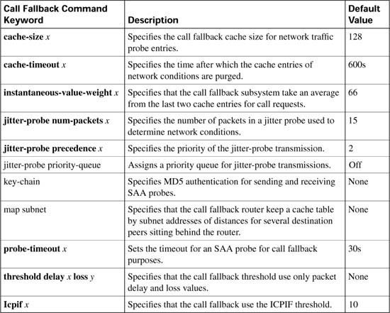
Table C-11 lists the options and default values of the call fallback command.
Examples C-13 and C-14 demonstrate PSTN fallback between a host and remote site. SAA is configured on the remote site to answer the probes from the host site. When the number 1234 is dialed from the host site and congestion is observed on the link between the host site and the remote site, the call is redirected to port 3/0:23 and connected to the remote site over the PSTN.
Probes are sent every 20 seconds with 15 packets in each probe. The probes share the priority queue with the other voice packets. The delay and loss threshold command is configured with a delay threshold of 150 ms and a loss threshold of 5 percent and the cache aging timeout is configured for 10,000 seconds.
Example C-13 shows the configuration for the host site router.
Example C-13 Call Fallback Host Site Configuration
!
call fallback threshold delay 150 loss 5
call fallback jitter-probe num-packets 15
call fallback jitter-probe priority-queue
call fallback cache-timeout 10000
call fallback active
interface Serial1/0
ip address 10.1.1.1 255.255.255.0
!
interface Serial3/0:23
no ip address
no logging event link-status
isdn switch-type primary-ni
isdn incoming-voice voice
no cdp enable
!
voice-port 3/0:23
!
dial-peer voice 100 voip
destination-pattern 12..
preference 1
session target ipv4:10.1.1.2
!
dial-peer voice 10 pots
destination-pattern 12..
preference 2
port 3/0:23
!Adds prefix in front of the dialed number route over the PSTN
prefix 9140455512
!
dial-peer voice 20 pots
destination-pattern 9T
port 3/0:23
Example C-14 shows the configuration for the remote site router.
Example C-14 Call Fallback Remote Site Configuration for Host Name Remote Site
interface Serial1/0
ip address 10.1.1.2 255.255.255.0
!
interface Serial3/0:23
no ip address
no logging event link-status
isdn switch-type primary-ni
isdn incoming-voice voice
no cdp enable
!
voice-port 3/0:23
!
dial-peer voice 100 voip
destination-pattern 5...
preference 1
session target ipv4:10.1.1.1
!
dial-peer voice 10 pots
destination-pattern 5...
preference 2
port 3/0:23
!Adds prefix in front of the dialed number route over the PSTN
prefix 914085555
!
dial-peer voice 20 pots
destination-pattern 9T
port 3/0:23
!
With the configuration of Examples C-13 and C-14, 15 probes are placed in the priority queue of the host site router every 20 seconds. The responses received from the remote site router must not exceed 150 ms of delay or 5 lost packets for the host site routers to determine that this path will support the QoS necessary for a voice conversation. If this path is not used in 10,000 seconds, it is removed from the cache and a new set of probes have to be launched at the next request. The rtr responder command is enabled on the remote site router to enable responses to the probes.
Examples C-13 and C-14 in the preceding section describe a simple network in which the remote site router acts as the terminating gateway for the voice conversation. The IP address of the remote site router and the network congestion values of the link between the remote and host router are held in the cache of the host site router. When the host site router receives the digits 12 followed by 2 additional digits, the host cache is consulted to determine whether the call can be successfully placed.
As the network becomes more complex, such as with the addition of IP telephony, it becomes necessary to designate a single terminating gateway to represent a number of IP destination devices. Consider the example illustrated in Figure C-16. There are a large number of IP Phones at Site 6, each one having a unique IP address.

If Site 1 calls an IP Phone at Site 6, the cache at Site 1 does not need to contain an entry for each separate IP destination at Site 6. All IP call destinations at Site 6 can be mapped to the IP address of the WAN edge router at Site 6 so that a single probe from Site 1 to Site 6 can be used to probe CAC information for all calls destined to Site 6. The same principle applies if there were multiple terminating gateways at Site 6.
The probe traffic can therefore be reduced substantially by sending probes to IP destinations that represent the portion of the network that is most likely to be congested, such as the WAN backbone and WAN edge. This same scalability technique also provides a mechanism to support IP destinations that do not support SAA responder functionality.
PSTN fallback is a widely deployable, topology-independent CAC mechanism that can be used over any backbone. Consider the following attributes of PSTN fallback when designing a network:
![]() Because it is based on IP probes, PSTN fallback applies to VoIP networks only.
Because it is based on IP probes, PSTN fallback applies to VoIP networks only.
![]() PSTN fallback does not reroute calls in progress when network conditions change.
PSTN fallback does not reroute calls in progress when network conditions change.
![]() A slight increase in postdial delay will apply to the first call to a destination not yet in the cache.
A slight increase in postdial delay will apply to the first call to a destination not yet in the cache.
![]() No interaction occurs between the SAA probe timer and the H.225 timer setting: The SAA probe occurs before the H.323 call setup is sent to the destination, and the H.225 timer occurs after H.323 call setup is sent.
No interaction occurs between the SAA probe timer and the H.225 timer setting: The SAA probe occurs before the H.323 call setup is sent to the destination, and the H.225 timer occurs after H.323 call setup is sent.
![]() PSTN fallback performs well in steady traffic that has a gradual ramp-up and ramp-down, but poorly in quickly fluctuating traffic with a bursty ramp-up and ramp-down.
PSTN fallback performs well in steady traffic that has a gradual ramp-up and ramp-down, but poorly in quickly fluctuating traffic with a bursty ramp-up and ramp-down.
![]() An erroneous CAC decision could be reached in a bursty environment based on noncurrent information due to the periodic nature of the probes.
An erroneous CAC decision could be reached in a bursty environment based on noncurrent information due to the periodic nature of the probes.
![]() Proxy destinations for the probes can be used by mapping destination IP addresses to a smaller number of IP addresses of the nodes located between the originating gateway and the terminating gateways.
Proxy destinations for the probes can be used by mapping destination IP addresses to a smaller number of IP addresses of the nodes located between the originating gateway and the terminating gateways.
![]() No bandwidth measurements are taken by the probes, delay and loss measurements only.
No bandwidth measurements are taken by the probes, delay and loss measurements only.
![]() MD5 keychain authentication can be configured for security to ensure that probes are initiated only by trusted sources, which will circumvent “denial-of-service” type attacks by untrusted sources initiating large volumes of probes.
MD5 keychain authentication can be configured for security to ensure that probes are initiated only by trusted sources, which will circumvent “denial-of-service” type attacks by untrusted sources initiating large volumes of probes.
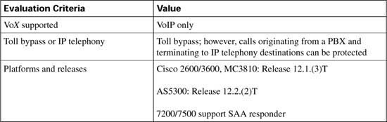
Table C-12 evaluates the PSTN fallback mechanism against the CAC evaluation criteria described earlier in this chapter.

There are two types of resource-based CAC mechanisms:
![]() Those that monitor the use of certain resources and calculate a value that affect the CAC decision
Those that monitor the use of certain resources and calculate a value that affect the CAC decision
![]() Those that reserve resources for the call
Those that reserve resources for the call
The reservation mechanisms are the only ones that can attempt to guarantee QoS for the duration of the call. All other local, measurement-based and resource calculation-based CAC mechanisms just make a one-time decision prior to call setup, based on knowledge of network conditions at that time.
The following resources are of interest to voice calls:
![]() DS0 time slot on the originating and terminating TDM trunks
DS0 time slot on the originating and terminating TDM trunks
![]() Digital signal processor (DSP) resources on the originating and terminating gateways
Digital signal processor (DSP) resources on the originating and terminating gateways
![]() CPU use of the involved nodes, typically the gateways
CPU use of the involved nodes, typically the gateways
![]() Memory use of the involved nodes, typically the gateways
Memory use of the involved nodes, typically the gateways
The following sections focus on the following four resource-based CAC techniques:
![]() Resource Availability Indication
Resource Availability Indication
![]() Gatekeeper Zone Bandwidth
Gatekeeper Zone Bandwidth
![]() Resource Reservation Protocol
Resource Reservation Protocol
Like the measurement-based CAC techniques, these techniques add visibility into the network itself in addition to the local information discussed in the previous sections.
To allow gatekeepers to make intelligent call routing decisions, the terminating gateway uses resource availability indication (RAI) to report resource availability to the gatekeeper. Resources monitored by the terminating gateway include DS0 channels and DSP channels. When a monitored resource falls below a configurable threshold, the gateway sends an RAI message to the gatekeeper indicating that the gateway is almost out of resources. When the available resources then cross above another configurable threshold, the gateway sends an RAI message indicating that the resource depletion condition no longer exists. The gatekeeper never has knowledge of the individual resources or the type of resources that the gateway considers. The RAI message is a simple yes or no toggle indication sent by the terminating gateway to control whether the gatekeeper should allow subsequent voice calls to be routed to the terminating gateway. The gatekeeper responds with a resource availability confirmation (RAC) upon receiving an RAI message to acknowledge its reception.
As a CAC mechanism, RAI is unique in its capability to provide information on the terminating POTS connection. Other mechanisms discussed in this chapter enable CAC decisions based on local information at the originating gateway and on the condition of the IP cloud between the originating gateway and terminating gateways. No other CAC mechanism has the capability to consider the availability of resources to terminate the POTS call at the terminating gateway. Another difference is that with RAI the CAC decision is controlled by the terminating gateway. In all the other methods, the CAC decision is controlled by the originating gateway or by the gatekeeper.
RAI was included in Cisco IOS Software Release 12.0(5)T on the Cisco AS5300 Gateway, and Cisco IOS Software Release 12.1(1)T for other gateways in H323v2.
The calculation to reach the CAC decision is performed by the terminating gateway. Different gateway platforms may use different algorithms. The H.323 standard does not prescribe the calculation or the resources to include in the calculation. It merely specifies the RAI message format and the need for the gatekeeper to discontinue routing calls to the terminating gateway in the event that the gateway has insufficient available resources for the additional call, and the gateway will inform the gatekeeper to resume routing calls when resources become free.
Calculating utilization first takes into account the number of accessible channels on the target device. Accessible channels are either active or idle voice channels on the device that are used to carry voice conversations. Disabled channels are not counted as accessible channels.
The following formula is used to determine accessible channels:
When the number of accessible channels is known, the utilization can be calculated from the following formula:
Suppose, for instance, that you have four T1 CAS circuits. Two of the T1 CAS circuits are used for incoming calls, and the remaining two T1 CAS circuits are used for outgoing calls. You have busied out 46 time slots of the outgoing time slots, and you have one call on one of the outgoing time slots. You will have the following:
![]() Total voice channels = 96
Total voice channels = 96
![]() Outgoing total voice channels = 48
Outgoing total voice channels = 48
![]() Disabled voice channels = 46
Disabled voice channels = 46
![]() Voice channels being used = 1
Voice channels being used = 1
![]() Free voice channels = 1
Free voice channels = 1
The outgoing accessible channels in this situation are as follows:
1 (voice channels being used) + 1 (free voice channels)= 2
The DS0 utilization for this device is as follows:
or
The utilization for the outgoing channels is equal to 50 percent. If the configured high threshold is 90 percent, the gateway will still accept calls. Only DS0s reachable through a VoIP dial peer are included in the calculation.
The preceding calculation took the DS0 resources into consideration. Remember that the DSP resources are monitored and calculated in the same manner. The terminating gateway sends an RAI message in the event that either the DS0 or DSP resources reach the low or high threshold.
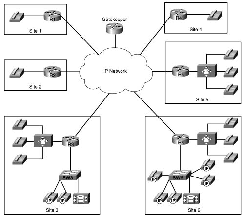
RAI is an indispensable feature in SP networks that provide VoIP calling services such as debit and credit card calling and VoIP long-distance phone service. Figure C-17 shows the general structure of these networks.
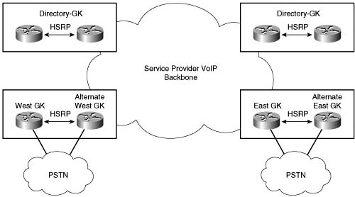
Around the world there are points of presence (POPs) where racks of gateways, such as Cisco AS5300 access servers, connect to the PSTN with T1/E1 trunks. The call routing is managed through several levels of gatekeepers as shown in Figure C-17. Call volume is high, and these gateways handle voice traffic only (no data traffic other than minimal IP routing and network management traffic).
When a customer on the West Coast dials a number residing on the East Coast PSTN, the East Coast gatekeeper must select an East Coast gateway that has an available PSTN trunk to terminate the call. If an East Cost gateway cannot be found, the customer’s call fails. In the event of a failed call, the originating gateway must retry the call or the customer must redial the call. In either case, there is no guarantee that the same out-of-capacity terminating gateway will not be selected again.
This scenario is inefficient and provides poor customer service. It is important that calls are not routed by the gatekeeper to a terminating gatekeeper that cannot terminate the call due to the lack of PSTN trunk capacity.
In general, calls are load balanced by the gatekeeper across the terminating gateways in its zone. But the gateways could have different levels of T1/E1 capacity and by load balancing across the gateways one gateway could become shorter on resources than another. It is in this situation that RAI is imperative. The overloaded terminating gateway has the capability to initiate an indication to the gatekeeper that it is too busy to take more calls.
RAI is generally less applicable in enterprise networks than in SP networks because there is often only one gateway at each site, as shown in Figure C-18. This is almost always true for the typical hub-and-spoke enterprise network. Even at the large sites, there may be multiple T1/E1 trunks to the attached PBX, but there are seldom multiple gateways.
If a single gateway is used to terminate a call, where the called user resides on a specific PBX and is reachable only through a specific gateway in the network, RAI does not provide additional network intelligence. With no alternate gateway to handle excess calls, a call will always fail whenever the single terminating gateway is too busy. In addition, in enterprise networks the probability of congestion is typically higher in the IP cloud than in the number of terminating POTS trunks. In the SP networks discussed earlier, congestion is more common in the terminating POTS trunks than in the IP cloud.
In spite of these limitations, RAI can still be used for enterprise networks provided the gateway to PBX connections at the remote sites consist of T1/E1 trunks. If a terminating gateway is too busy, it triggers a PSTN reroute instead of selecting an alternate gateway as in the SP network situation.
The discussion of where and how RAI is used in SP and enterprise networks clearly shows that RAI is most useful in situations where multiple terminating gateways can reach the same destination, or called, phone number. However, RAI has value in any situation where there is a desire to prevent a call from being routed to a gateway that does not have the available POTS capacity to terminate the call.
When a gatekeeper receives an RAI unavailable indication from a gateway, it removes that gateway from its gateway selection algorithm for the phone numbers that gateway would normally terminate. An RAI available indication received later returns the gateway to the selection algorithm of the gatekeeper.
RAI is an optional H.323 feature. When you implement a network, therefore, it is prudent to verify that both the gateways and gatekeepers support this feature. Cisco gatekeepers support RAI. Cisco gateway support for RAI is detailed in a later section of this chapter.
RAI on the gateway is configured with high-water- and low-water-mark thresholds, as shown in Figure C-19. When resource usage rises above the high-water mark, an RAI unavailable indication is sent to the gatekeeper. When resource availability falls below the low-water mark, an RAI available indication is sent to the gatekeeper. To prevent hysteresis based on the arrival or disconnection of a single call, the high- and low-water marks should be configured 10 percentage points apart. (Hysteresis refers to the process of switching a feature on, then off, then on, and so on, over and over again, as would happen if the high- and low-water marks were configured to very similar values.)

To configure RAI, use the following gateway configuration command:
To configure an RAI unavailable resource message to be sent to the gatekeeper at a high-water mark of 90 percent and a RAI available resource message to be sent to the gatekeeper at a low-water mark of 80 percent, enter the following command:
The Cisco AS5300 access server has supported RAI since Cisco IOS Release 12.0(5)T. The Cisco 2600 and 3600 series routers have supported RAI for T1/E1 connections only, not for analog trunks, since Release 12.1.3T. The other Cisco IOS gateways do not yet support RAI as of Release 12.1(5)T or 12.2. The RAI calculation includes digital signal processors (DSPs) and DS0s, and may not be the same for all platforms. In current software, CPU and memory are not yet included in the RAI availability indication.
Table C-13 evaluates the RAI mechanism against the CAC evaluation criteria described earlier in this chapter.
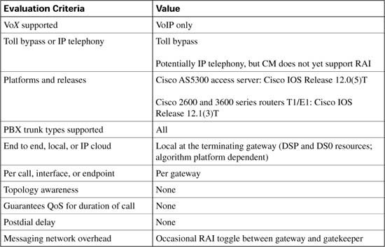
The term “locations” refers to a CAC feature in a Cisco CallManager centralized call-processing environment. Because a centralized call-processing model is deployed in a hub-and-spoke fashion without the use of a terminating gateway at each spoke, an IP telephony CAC mechanism must be used to protect the desired number of voice conversations. Locations are designed to work in this nondistributed environment.
Figure C-20 shows a typical CallManager centralized call-processing model.

The Cisco CallManager centralized call-processing model uses a hub-and-spoke topology. The host site, or hub, is the location of the primary Cisco CallManager controlling the network while the remote sites, containing IP endpoints registered to the primary CallManager, represent the spokes. The Cisco CallManager Administration web page can be used to create locations and assign IP endpoints, such as IP Phones, to these locations. After the locations have been created and devices have been assigned, you can allocate bandwidth for conversations between the hub and each spoke locations.
For calls between IP endpoints in the host site of Figure C-20, the available bandwidth is assumed to be unlimited, and CAC is not considered. However, calls between the host site and remote sites travel over WAN links that have limited available bandwidth. As additional calls are placed between IP endpoints over the WAN links, the audio quality of each voice conversation can begin to degrade. To avoid this degradation in audio quality in a CallManager centralized call-processing deployment, you can use the locations feature to define the amount of available bandwidth allocated to CallManager controlled devices at each location and thereby decrease the number of allowed calls on the link.
The amount of bandwidth allocated by CallManager locations is used to track the number of voice conversations in progress across an IP WAN link on a per-CallManager basis. CallManager servers in a cluster are not aware of calls that have been set up by other members in the cluster. To effectively use location-based CAC, all devices in the same location must register with the same centralized CallManager server.
In Cisco CallManager, locations work in conjunction with regions to define how voice conversations are carried over a WAN link. Regions define the type of compression, such as G.711 or G.729, used on the link, and locations define the amount of available bandwidth allocated for that link.
Figure C-21 illustrates a CallManager centralized call-processing model with three remote sites. Each remote site has a location name that all IP endpoints in that location are associated with and a region that determines which codec is be used for voice conversations to IP endpoints in this location.
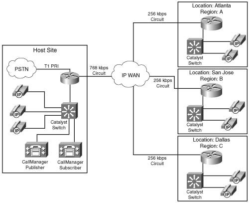
Each IP endpoint uses the G.711 codec for voice conversations with other endpoints in the same region. When an IP endpoint establishes a voice conversation with an IP endpoint in another region, the G.729 codec is used. The following examples illustrate this:
After the regions have been defined and all devices have been configured to reside in the desired location, you can begin to allocate the desired bandwidth between the locations to use for CAC. This allocated bandwidth does not reflect the actual bandwidth required to establish voice conversations; instead, the allocated bandwidth is a means for CallManager to provide CAC. CAC is achieved by defining a maximum amount of bandwidth per location to use and then subtract a given amount, dependent upon the codec used, from that maximum for each established voice conversation. In this way, CallManager has the capability to deny or reroute call attempts that exceed the configured bandwidth capacity.
Table C-14 shows the amount of bandwidth that is subtracted, per call, from the total allotted bandwidth for a configured region.

In Figure C-21, suppose that you need to protect six simultaneous calls between the HQ and Atlanta locations, but allow only four between the HQ and Dallas location and three between the HQ and San Jose location. Because each region has been configured to use the G.729 codec between regions, each of these voice conversations represent 24 kbps to the configured location. Remember that the location bandwidth does not represent the actual bandwidth in use.
For the Atlanta location to allow 6 simultaneous calls, the Atlanta Location Bandwidth needs to be configured for 144 kbps, as shown in the following calculation:
For the Dallas location to allow 4 simultaneous calls, the Dallas location bandwidth needs to be configured for 48 kbps, as shown in the following calculation:
Finally, for the San Jose location to allow 3 simultaneous calls, the San Jose location bandwidth needs to be configured for 72 kbps, as shown in the following calculation:
The link to the Atlanta location, configured for 144 kbps, could support 1 G.711 call at 80 kbps, 6 simultaneous G.729 calls at 24 kbps each, or 1 G.711 call and 2 G.729 calls simultaneously. Any additional calls that try to exceed the bandwidth limit are rejected and the call is either rerouted or a reorder tone returns to the caller.
CallManager continues to admit new calls onto a WAN link until the available bandwidth for that link (bandwidth allocated to the location minus all active voice conversations) drops below zero.
Prior to CallManager version 3.3, if a call was blocked due to insufficient location bandwidth, the caller would receive a reorder tone and manually have to redial the called party through the PSTN. Automated alternate routing (AAR), introduced in CallManager version 3.3, provides a mechanism to reroute calls through the PSTN or another network WAN link by using an alternate number when Cisco CallManager blocks a call because of insufficient location bandwidth. With automated alternate routing, the caller does not need to hang up and redial the called party.
The fully qualified E.164 address, also known as the PSTN number, is obtained from the external phone number mask configured on the called device. The calling device is associated with an AAR group, which is configured with the digits that will be prepended to the phone number mask to access the PSTN gateway and reroute the call over the PSTN.
Table C-15 evaluates location-based CAC against the CAC evaluation criteria described earlier in this chapter.


The gatekeeper function is an IOS-based mechanism specific to H.323 networks. Different levels of Cisco IOS Software provide various, specific capabilities within this feature. In Cisco IOS Releases 12.1(5)T and 12.2, the gatekeeper function has the capability to limit the number of simultaneous calls across a WAN link similar to the CallManager location-based CAC discussed in the preceding section.
By dividing the network into zones, a gatekeeper can control the allocation of calls in its local zone and the allocation of calls between its own zone and any other remote zone in the network. For the purpose of understanding how this feature operates, assume a voice call is equal to 64 kbps of bandwidth. Actual bandwidth used by calls in a gatekeeper network are addressed in the “Zone Bandwidth Calculation” section.
Figure C-22 shows a single-zone gatekeeper network with two gateways that illustrates gatekeeper CAC in its simplest form. If the WAN bandwidth of the link between the two gateways can carry no more than two calls, the gatekeeper must be configured so that it denies the third call. Assuming every call is 64 kbps, the gatekeeper is configured with a zone bandwidth limitation of 128 kbps to achieve CAC in this simple topology.

Most networks, however, are not as simple as the one shown in Figure C-22. Figure C-23 shows a more complex topology; however, it is still configured as a single-zone network. In this topology, the legs in the WAN cloud each have separate bandwidth provisioning and therefore separate capabilities of how many voice calls can be carried across each leg. The numbers on the WAN legs in Figure C-23 show the maximum number of calls that can be carried across each leg.

Assume that the gatekeeper zone bandwidth is still configured to allow a maximum of 128 kbps, limiting the number of simultaneous calls to two.
With a single zone configured, the gatekeeper protects the bandwidth of the WAN link from Site 1 to the WAN aggregation point by not allowing more than two calls across that link. When two calls are in progress, however, additional calls between the PBXs at Headquarters are blocked even though there is ample bandwidth in the campus backbone to handle the traffic.
To solve the single-zone problem of reducing the call volume of the network to the capabilities of the lowest-capacity WAN link, you can design multiple gatekeeper zones into the network. A good practice in designing multiple zones is to create one zone per site, as shown in Figure 8-24.
The Site 1 gatekeeper limits the number of calls active in Site 1, regardless of where those calls originate or terminate, to two simultaneous calls by limiting the available bandwidth to 128 kbps. Because there is only one gateway at Site 1, there is no need to configure a limit for the intrazone call traffic. All interzone traffic is limited to two calls to protect the WAN link connecting Site 1.
At Site 2 there is also a single gateway, and therefore no need to limit the intrazone call traffic. There are separate interzone limits for the following scenarios:
![]() Calls between Site 2 and the Headquarters site are limited to a maximum of four calls on the WAN link connecting Site 2.
Calls between Site 2 and the Headquarters site are limited to a maximum of four calls on the WAN link connecting Site 2.
![]() Calls between Site 2 and Site 1 are limited to a maximum of two calls on the WAN link connecting Site 1.
Calls between Site 2 and Site 1 are limited to a maximum of two calls on the WAN link connecting Site 1.
The Headquarters site has a similar configuration to Site 2 except that calls are unlimited within Headquarters; not because there is a single gateway, but because there is ample bandwidth between the gateways at this site.
In the network topology in Figure C-24, gatekeeper CAC provides sufficient granularity needed to protect voice conversations across the low-speed WAN links. Consider another network topology in which there are multiple gateways per zone, however, with each gateway at the remote sites having a separate WAN connection to the aggregation point. Figure C-25 shows such a network topology.

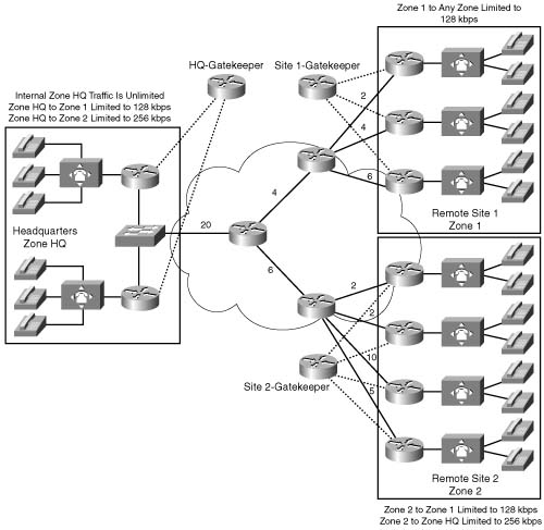
Of the three gateways in remote Site 1, the slowest WAN access link can carry a maximum of two simultaneous calls. Because the gatekeeper bandwidth limitation is configured per zone and not per gateway, there is no facility within gatekeeper CAC to limit the calls to specific gateways within the zone. To ensure protection of voice conversations, the zone bandwidth must be configured for the slowest link in the zone. For both remote Sites 1 and 2, the slowest link is 128 kbps bandwidth or two calls.
This configuration ensures proper voice quality at all times, but it is also wasteful of the gateways that could terminate more calls without oversubscribing their WAN bandwidth. In this network configuration, CAC is activated too soon and reroutes calls over to the PSTN when in fact they could have been carried by the WAN. In this type of topology, gatekeeper CAC is not sufficient to protect voice quality over the WAN link, and, at the same time, optimize the bandwidth use of all WAN links.
The last configuration to consider is an SP network where the gateways in the POPs are connected via Fast Ethernet to the WAN edge router, as shown in Figure C-26.

In this network, gatekeeper CAC is sufficient, even though there are multiple gateways per zone, because the connections to specific gateways within the zone are not the links that need protection. The bandwidth that needs protection is the WAN access link going into the backbone that aggregates the call traffic from all gateways. A gatekeeper bandwidth limitation for the zone indeed limits the number of calls over that link. It is assumed that the OC-12 backbone link is overengineered and requires no protection.
In summary, a multizone gatekeeper network offers the following CAC attributes:
![]() The WAN bandwidth at each connecting site can be protected, provided each site is also a zone. For small remote sites in an enterprise network, this often translates into a zone per gateway, which might not be a practical design.
The WAN bandwidth at each connecting site can be protected, provided each site is also a zone. For small remote sites in an enterprise network, this often translates into a zone per gateway, which might not be a practical design.
![]() The bandwidth within a site can be protected if necessary, but this is frequently of little value because there is only one gateway in the site (small remote offices, or a customer premises equipment [CPE] entry point to an SP-managed network service) or because a high-speed LAN is between the gateways (large sites and SP POPs).
The bandwidth within a site can be protected if necessary, but this is frequently of little value because there is only one gateway in the site (small remote offices, or a customer premises equipment [CPE] entry point to an SP-managed network service) or because a high-speed LAN is between the gateways (large sites and SP POPs).
![]() Gatekeeper CAC is a method well suited to limit the number of calls between sites.
Gatekeeper CAC is a method well suited to limit the number of calls between sites.
Gatekeeper CAC cannot protect the bandwidth on WAN segments not directly associated with the zones. For example, gatekeeper CAC cannot protect the backbone link marked with 20 calls in the simple enterprise topology shown in Figure C-24, unless the slowest link approach is followed.
Because the zone-per-gateway design offers the finest granularity of gatekeeper CAC, it is worth exploring a little further. In enterprise networks, this often makes sense from the following points of view:
![]() Geographical considerations
Geographical considerations
![]() CAC to protect the WAN access link into a site containing a single gateway
CAC to protect the WAN access link into a site containing a single gateway
![]() Dialing plans that coincide with sites, allowing a zone prefix to easily translate to the gateway serving a specific site
Dialing plans that coincide with sites, allowing a zone prefix to easily translate to the gateway serving a specific site
A gatekeeper is a logical concept, not a physical concept. Each gatekeeper therefore does not imply that there is a separate box in the network; it merely means that there is a separate local zone statement in the configuration.
With Cisco IOS Release 12.1(5)T and Release 12.2, a small remote site router has the capability to provide gateway, gatekeeper, and WAN edge functionality; however, a zone-per-gateway design complicates the scalability aspect that gatekeepers bring to H.323 networks. You should therefore carefully consider the advantages and limitations of such a design.
Of all the CAC mechanisms discussed in this chapter, gatekeeper zone bandwidth is the only method applicable to multi-site distributed CallManager clusters. In this scenario, the CallManager behaves like a VoIP gateway to the H.323 gatekeeper, as is shown in Figure C-27.

In this example, the CallManager in Zone 2 requests the WAN bandwidth to carry a voce conversation from the gatekeeper on behalf of the IP Phone x2111. The gatekeeper determines whether each zone has sufficient bandwidth to establish the call. If the gatekeeper allows the call to proceed, the CallManager in Zone 2 contacts the CallManager in Zone 1 to begin call setup. If the gatekeeper rejects the call, the CallManager in Zone 2 can reroute the call over the PSTN to reach the called party.
The gatekeeper does not have any knowledge of network topology and does not know how much bandwidth is available for calls. Nor does the gatekeeper know how much of the configured bandwidth on the links is currently used by other traffic. The gatekeeper takes a fixed amount of bandwidth, statically configured on the gatekeeper, and subtracts a certain amount of bandwidth for each call that is set up. Bandwidth is returned to the pool when a call is disconnected. If a request for a new call causes the remaining bandwidth to become less than zero, the call is denied. The gatekeeper does not use bandwidth reservation. Instead, the gatekeeper performs a static calculation to decide whether a new call should be allowed.
It is the responsibility of the gateways to inform the gatekeeper of how much bandwidth is required for a call. Video gateways therefore could request a different bandwidth for every call setup. One video session may require 256 kbps, whereas another requires 384 kbps. Voice gateways should consider codec, Layer 2 encapsulation, and compression features, such as compressed Real Time Protocol (cRTP), when requesting bandwidth from the gatekeeper. Sometimes these features are not known at the time of call setup, in which case a bandwidth change request can be issued to the gatekeeper after call setup to adjust the amount of bandwidth used by the call. As of Cisco IOS Software Release 12.2(2)XA, Cisco has implemented only the functionality of reporting any bandwidth changes when the reported codec changes.
Prior to Cisco IOS Software Release 12.2(2)XA on a Cisco H.323 Gateway, calls were always reported to require a bandwidth of 64 kbps. This is the unidirectional payload bandwidth for a Cisco G.711 codec. If the endpoints in the call chose to use a more efficient codec, this was not reported to the Cisco gatekeeper. In the Cisco IOS Software Release 12.2(2)XA version of the Cisco H.323 Gateway or a later version that conforms with H.323 version 3, the reported bandwidth is bidirectional. Initially, 128 kbps is specified. If the endpoints in the call select a more efficient codec, the Cisco gatekeeper is notified of the bandwidth change.
Figure C-28 illustrates a network that uses a gatekeeper to limit bandwidth to 144 kbps between two zones. A connection is requested with an initial bandwidth of 128 kbps. After the call has been set up, the endpoints report the change in the bandwidth. Assuming the endpoints are using G.729, 16 kbps is subtracted from the configured maximum of 144 kbps. The 16 kbps represents a bidirectional G.729 payload stream to the gatekeeper.

In the event that the second call arrives before the endpoint requests the change in bandwidth for the first call, the Cisco gatekeeper rejects the second call, because the total requested bandwidth exceeds the 144 kpbs configured. As call 1 is being set up, for example, the gatekeeper records this call as a 12C-kbps call and waits for a codec change before adjusting the recorded bandwidth. At this point, the gatekeeper has subtracted 128 kbps from the configured 144 kbps, leaving 16 kbps available. If call 2 requests admission before the codec change is reported in call 1, the gatekeeper does not have enough available bandwidth to allow this 12C-kbps call to proceed.
Gatekeeper zone bandwidth remains an inexact science because the gateway may not have full knowledge of the bandwidth required by the call. The following examples describe common situations where the gateway will not have full knowledge of the bandwidth required per call:
![]() The gateway is attached to an Ethernet segment in a campus network where cRTP does not apply and where the Layer 2 headers are larger than they would be for Frame Relay or Multilink Point-to-Point Protocol (MLP) on the WAN legs.
The gateway is attached to an Ethernet segment in a campus network where cRTP does not apply and where the Layer 2 headers are larger than they would be for Frame Relay or Multilink Point-to-Point Protocol (MLP) on the WAN legs.
![]() A different codec is used in the campus network from the WAN segments, leveraging codec transcoding functionality at the WAN edge.
A different codec is used in the campus network from the WAN segments, leveraging codec transcoding functionality at the WAN edge.
![]() In the backbone of the network, ATM is used as the transport technology. In this case, cell padding should be taken into account for bandwidth calculations.
In the backbone of the network, ATM is used as the transport technology. In this case, cell padding should be taken into account for bandwidth calculations.
![]() cRTP may be used at the WAN edge router.
cRTP may be used at the WAN edge router.
As of Cisco IOS Software Release 12.1(5)T and Release 12.2, the following types of zone bandwidth limitations can be configured on the gatekeeper:
![]() The maximum bandwidth for all H.323 traffic between the local zone and a specified remote zone.
The maximum bandwidth for all H.323 traffic between the local zone and a specified remote zone.
![]() The maximum bandwidth allowed for a single session in the local zone. This configuration is typically used for video applications, not for voice.
The maximum bandwidth allowed for a single session in the local zone. This configuration is typically used for video applications, not for voice.
![]() The maximum bandwidth for all H.323 traffic allowed collectively to all remote zones.
The maximum bandwidth for all H.323 traffic allowed collectively to all remote zones.
Tables C-16 and C-17 list the gatekeeper command and options used to configure gatekeeper zone bandwidth.
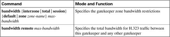

Gatekeeper CAC works well in network designs where the desire is to limit the number of calls between sites. This may be required due to either bandwidth limitations or business policy. If bandwidth limitations are on the WAN links, manual calculations can be performed to translate the maximum number of calls allowed between sites into a bandwidth figure that will cause the gatekeeper to deny calls when the calculated number is exceeded.
Gatekeepers do not share database information. If the primary gatekeeper fails, a secondary gatekeeper can begin to perform CAC for the network; however, the secondary gatekeeper has no knowledge of the amount of bandwidth currently used in the zone or the true number of active voice conversations. Until the secondary gatekeeper has an accurate count of current calls and consumed bandwidth, the network may become oversubscribed with voice conversations. If alternate gatekeepers are used as the redundancy method, this problem is circumvented.
A major advantage of gatekeeper CAC is that it is the only CAC method that can incorporate mixed networks of Cisco IOS gateways and CallManagers with IP Phones.
Table C-18 evaluates the gatekeeper zone bandwidth mechanism against the CAC evaluation criteria described earlier in this chapter.
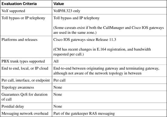
In Chapter 2, “QoS Tools and Architectures,” this book introduced the concepts of differentiated services (DiffServ) and integrated services (IntServ). Most of the rest of the chapters in this book cover QoS features that either use DiffServ, or behave similarly. This section covers some of the key concepts and configuration related to IntServ.
The IntServ model, defined in RFC 1633, includes provisions for best-effort traffic, real-time traffic, and controlled-link sharing. Controlled-link sharing is a management facility that enables administrators to divide traffic into classes and assign a minimum percentage of the link to each desired class during times of congestion, while sharing this assigned bandwidth with other classes when congestion is not present.
In the IntServ model, an application requests a specific level of service from the network before sending data. An application informs the network of its traffic profile by sending an explicit signaling message, requesting a particular level of service based on bandwidth and delay requirements. The application is expected to send data only after it gets a confirmation from the network.
The network performs admission control, based on information from the application and available network resources. The network also commits to meeting the QoS requirements of the application as long as the traffic remains within the profile specifications. After a confirmation from the network has been received, the application can send data that conforms to the described traffic profile. The network fulfills its commitment by maintaining per-flow state and then performing packet classification, policing, and intelligent queuing based on that state.
The Resource Reservation Protocol (RSVP) defines the messages used to signal resource admission control and resource reservations conforming to IntServ. When the application signals the required level of service, if resources are available, the network devices accept the RSVP reservation.
To provide the committed service levels, the networking devices must identify packets that are part of the reserved flows, and provide appropriate queuing treatment. When committing service to a new flow, Cisco IOS installs a traffic classifier in the packet-forwarding path, allowing the network devices to identify packets for which a reservation has been made. To provide the required service level, Cisco IOS uses existing QoS tools.
Most networks that use RSVP and IntServ also use DiffServ features as well. For instance, the same queuing tool that provides minimum bandwidth commitments for DiffServ can also be used to dynamically reserve bandwidth for IntServ and RSVP. As noted in Chapter 2, DiffServ does scale much better than IntServ. Cisco has a relatively new feature called RSVP aggregation, which integrates resource-based admission control with DiffServ, which allows for better scalability, but with strict QoS guarantees for prioritized traffic, such as VoIP calls.
To request a level of service from the network, the acceptable levels of service must be defined. Currently RSVP defines three distinct levels of service:
![]() Guaranteed QoS
Guaranteed QoS
![]() Controlled-load network element service
Controlled-load network element service
![]() Best-effort levels of service
Best-effort levels of service
The guaranteed QoS level of service is used to guarantee that the required bandwidth can be provided to a flow with a fixed delay. This service makes it possible to provide a service that guarantees both delay and bandwidth. This type of RSVP service is used by voice gateways when reserving bandwidth for voice flows.
The controlled-load level of service tightly approximates the behavior visible to applications receiving best-effort service under uncongested conditions from the same series of network elements. So, if the application can work well when the network is uncongested, the controlled load level of RSVP service can work well. If the network is functioning correctly with controlled-load service, applications may assume the following:
![]() Very low loss—If the network is not congested, queues will not fill, so no drops occur in queues. The only packet loss occurs due to transmission errors.
Very low loss—If the network is not congested, queues will not fill, so no drops occur in queues. The only packet loss occurs due to transmission errors.
![]() Very low delay and jitter—If the network is not congested, queues will not fill, and queuing delay is the largest variable component of both delay and jitter.
Very low delay and jitter—If the network is not congested, queues will not fill, and queuing delay is the largest variable component of both delay and jitter.
The best-effort level of service does not grant priority to the flow. The flow receives the same treatment as any other flow within the router.
RSVP uses path and resv messages to establish a reservation for a requested data flow. A path message carries the traffic description for the desired flow from the sending application to the receiving application, and the resv message carries the reservation request for the flow from the receiving application to the sending application. Figure C-29 shows a network that consists of several routers carrying the path and resv messages for a sending and receiving application.

In this example, the sending application responds to an application request by sending a path message to the RSVP router R1 describing the level of service required to support the requested application. R1 forwards the path message to router R2, R2 forwards the message to router R3, R3 forwards the message to R4, and finally R4 forwards the message to the receiving application. If the level of service described in the path message can be met, the receiving application sends a resv message to RSVP router R4. The resv message causes each router in the data path to the sending application to place a reservation with the requested level of service for the flow. When the resv message reaches the sending application, the data flow begins.
Path messages describe the level of service required for a particular flow through the use of the Sender_Tspec object within the message. The Sender_TSpec object is defined by the sending application and remains in tact as the path message moves through the network to the receiving application. Also included in the path message is the ADSpec object. The ADSpec object is modified by each intermediary router as the RSVP path message travels from the sending application to the receiving application. The ADSpec object carries traffic information generated by the intermediary routers. The traffic information describes the properties of the data path, such as the availability of the specified level of service. If a level of service described in the ADSpec object is not implemented in the router, a flag is set to alert the receiving application.
Effectively, the Sender_Tspec states what the application needs, and the ADSpec allows each successive router to comment on the level of service it can and cannot support. The receiving application can look at both settings and decide whether to accept or reject the reservation request. Figure C-30 shows the Sending_TSpec and ADSpec objects sent in a path message from a sending application.

In Figure C-30 the Sending_TSpec is advertising the required level of service for this application as guaranteed. Because intermediary routers do not modify the Sending_TSpec, this value is passed through the network to the receiving application. The ADSpec lists the level of service available at each intermediate router along the data path. As the path message reaches router R3, the ADSpec object is modified to indicate that router R3 can only provide a controlled-load level of service. Essentially, the sending application has asked for guaranteed RSVP service, and the ADSpec implies that at least one router can only support a controlled-load service for this request.
The receiver of the path message replies with an resv message. Resv messages request a reservation for a specific flow through the use of a FlowSpec object. The FlowSpec object provides a description of the desired flow and indicates the desired level of service for the flow to the intermediary routers, based on the information received from the path message in the ADSpec object. A single level of service must be used for all nodes in the network—in other words, it can be controlled-load or guaranteed service, but not both. Because the sending application requires either guaranteed or controlled-load level of service to begin the flow, and router R3 can only provide controlled-load level of service, the receiving application can only request a reservation specifying controlled-load level of service. Example C-31 shows the FlowSpec object sent in a resv message from a receiving application.

After the reservation for controlled-load service has been installed on the intermediary routers, the flow is established between the sending application and the receiving application.
Voice gateways use H.323 signaling when setting up voice calls. To reserve network resources for voice calls with RSVP, RSVP in an H.323 environment operates by synchronizing its signaling with H.323 version 2 signaling. This synchronization ensures a bandwidth reservation is established in both directions before a call moves to the alerting, or ringing, H.323 state. RSVP and H.323 version 2 synchronization provides the voice gateways with the capability to modify H.323 responses based on current network conditions. These modifications allow a gateway to deny or reroute a call in the event that QoS cannot be guaranteed.
Figure C-32 shows a call flow of the H.323 call setup messages and the RSVP reservation messages.
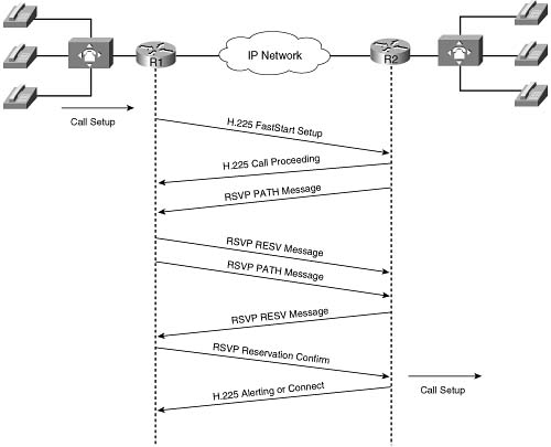
In this example, the originating gateway initiates a call to the terminating gateway with an H.225 setup message. The terminating gateway responds with a call proceeding message. Because voice conversations require a bidirectional traffic stream, each gateway initiates a reservation request by sending an RSVP path message. An RSVP resv message is sent in response indicating that the requested reservation has been made. The originating gateway sends an RSVP resvconf message to the terminating gateway confirming the reservation. At this point, the terminating gateway proceeds with the H.323 call setup by sending an alerting message to the originating gateway.
To configure RSVP for use with H.323, you need to enable RSVP as normal and add a few commands to the H.323 dial peers. By default, RSVP is disabled on each interface to remain backward compatible with systems that do not implement RSVP. To enable RSVP for IP on an interface, use the ip rsvp bandwidth command. This command starts RSVP and sets the maximum bandwidth for all RSVP flows combined, and a single-flow bandwidth limit. The default maximum bandwidth is up to 75 percent of the bandwidth available on the interface. By default, a single flow has the capability to reserve the entire maximum bandwidth.
To configure a network to use RSVP, regardless of whether it is used for voice calls, you just configure the ip rsvp bandwidth command on every link in the network. You also need to configure a queuing tool that supports RSVP on each interface, namely WFQ, IP RTP Priority, or LLQ. Configuration details are listed later in this section.
To use RSVP to allow voice gateways to reserve bandwidth for voice calls, RSVP synchronization must be configured on the voice gateways. When doing so, each dial peer is configured with an accept QoS (acc-qos) value, and a request QoS (req-qos) value. Each of these two settings indicates the level of service that the dial peer will request, and the level that it will accept to make a reservation. Table C-19 describes the available options for the acc-qos and req-qos commands.

This table was derived from the following: www.cisco.com/en/US/partner/products/sw/iosswrel/ps1834/products_feature_guide09186a008008045c.html.
For instance, two voice gateways could be configured to request, and to only accept, guaranteed-delay service. That combinations make sense with voice CAC—voice calls need a particular amount of bandwidth, and they need low delay. Examples C-15 and C-16 demonstrate the requested QoS and acceptable QoS dial-peer configuration of the req-qos and acc-qos commands, respectively.
Example C-15 Originating Gateway req-qos and acc-qos Dial-Peer Configuration
destination-pattern 3......
session target ipv4:10.1.1.1
!Configures RSVP CAC for voice calls using the dial peer.
acc-qos guaranteed-delay
Example C-16 Terminating Gateway req-qos and acc-qos Dial-Peer Configuration
destination-pattern 3......
session target ipv4:10.1.1.2
!Configures RSVP CAC for voice calls using the dial peer.
acc-qos guaranteed-delay
RSVP and H.323 synchronization has an added oddity that is not obvious at first glance. H.323 call setup actually includes two sets of call setup messages: one for the voice that travels in one direction, and another set for the voice in another direction. Each of the two requires a separate RSVP reservation. In addition to that, depending on what has been configured on the originating and terminating gateways, the gateways may request a high level of service (for example, guaranteed load), and be willing to accept a lower level of service. So, Table C-20 summarizes the results of nine call setup scenarios based on the QoS levels that can be configured in the VoIP dial peers at the originating and terminating gateways. This table does not include cases where the requested QoS is configured for best effort and the acceptable QoS is configured for a value other than best effort, because those configurations are considered invalid.
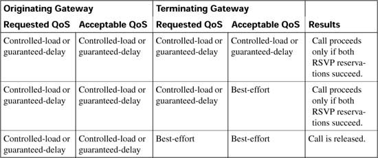

In Examples C-15 and C-16, the dial-peer configuration for both the originating and terminating gateway were configured for guaranteed-delay. Based on Table C-20, the call will proceed only if both RSVP reservations succeed.
As you learned in previous chapters, LLQ is one of the most important Cisco QoS mechanisms to ensure quality for voice conversations, because it prioritizes voice packets over data packets at the router egress interface. For this to work, voice packets must be classified such that they are placed in the priority queue (PQ) portion of LLQ.
Cisco IOS provides the service levels that RSVP accepts by working in conjunction with IOS queuing tools. As a general Cisco IOS feature, RSVP has its own set of reserved queues within Class-Based Weighted Fair Queuing (CBWFQ) for traffic with RSVP reservations. So, RSVP can create hidden queues that compete with the explicitly defined CBWFQ queues, with the RSVP queues getting very low weights—and remember, with all WFQ-like features, lower weight means better service.
You would just configure CBWFQ, and then RSVP, and not consider the two features together. However, the performance of the voice flows with RSVP reservations would actually suffer. The reason is that the reserved hidden RSVP queues, although they have a low weight, are separate from the PQ feature of CBWFQ/LLQ. Packets in reserved RSVP queues do not get strict priority over packets from other queues. It has long been known that this treatment, a low-weight queue inside WFQ, is insufficient for voice quality over a congested interface. Therefore, when RSVP is configured for a voice call, the voice packets need to be classified into the PQ.
IOS solves the problem by having RSVP put voice-like traffic into the existing LLQ priority queue on the interface. RSVP uses a profile to classify a flow of packets as a voice flow. The profile considers packet sizes, arrival rates, and other parameters to determine whether a packet flow is considered a voice flow. The internal profile, named voice-like, is tuned to classify all voice traffic originating from a Cisco IOS gateway as a voice flow without the need for additional configuration. Therefore, while RSVP makes the reservations, it then in turn classifies voice-like traffic into the LLQ PQ, and other non-voice-like traffic with reservations into RSVP queues, as shown in Figure C-33.
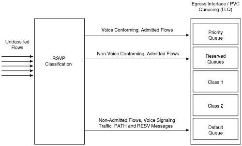
To perform the extra classification logic shown in the figure, RSVP is the first egress interface classifier to examine an arriving packet. If RSVP considers the packet a voice flow, the packet is put into the PQ portion of LLQ. If the flow does not conform to the voice profile voice-like, but is nevertheless an RSVP reserved flow, it is placed into the normal RSVP reserved queues. If the flow is neither a voice flow, nor a data RSVP flow, LLQ classifies the packet as it normally would.
Although RSVP voice traffic can be mixed with traffic specified in the priority class within a policy map, voice quality can suffer if both methods are implemented simultaneously. The two methods do not share bandwidth allocation and therefore will lead to an inefficient use of bandwidth on the interface. As bandwidth is defined in the configuration for the egress interfaces, all the bandwidth and priority classes will be allocated bandwidth at configuration time. No bandwidth is allocated to RSVP at configuration time because RSVP requests its bandwidth when the traffic flow begins. RSVP therefore gets allocated bandwidth from the pool that is left after the other features have already allocated their bandwidth.
It is important to note that RSVP classifies only voice bearer traffic, not signaling traffic. Another classification mechanism such as an ACL or DiffServ code point (DSCP) / IP precedence must still be used to classify the voice-signaling traffic if any treatment better than best effort is desired for signaling traffic.
Both LLQ and RSVP see the Layer 3 IP packet. Layer 2 encapsulations (FR, MLPPP, and so on) are added after queuing, so the bandwidth allocated by both LLQ and RSVP for a call is based on the Layer 3 bandwidth of the packets. This number is slightly different from the actual bandwidth used on the interface after Layer 2 headers and trailers have been incorporated. RSVP bandwidth reserved for a call also excludes both cRTP and VAD. Table C-21 summarizes the bandwidth RSVP allocates for calls using different Cisco IOS gateway codecs.

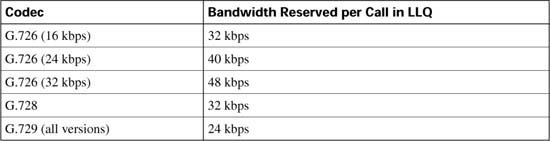
Subnet bandwidth management (SBM) specifies a signaling method and protocol for LAN-based CAC for RSVP flows. SBM allows RSVP-enabled Layer 2 and Layer 3 devices to support reservation of LAN resources for RSVP-enabled data flows.
SBM uses the concept of a designated entity elected to control the reservations for devices on the managed LAN. The elected candidate is called the designated subnetwork bandwidth manager (DSBM). It is the DSBM’s responsibility to exercise admission control over requests for resource reservations on a managed segment. A managed segment includes a Layer 2 physical segment shared by one or more senders, such as a shared Ethernet network. The presence of a DSBM makes the segment a managed one. One or more SBMs may exist on a managed segment, but there can be only one DSBM on each managed segment. A router interface can be configured to participate in the DSBM election process. The contender configured with the highest priority becomes the DSBM for the managed segment.
Figure C-34 shows a managed segment in a Layer 2 domain that interconnects a group of routers.
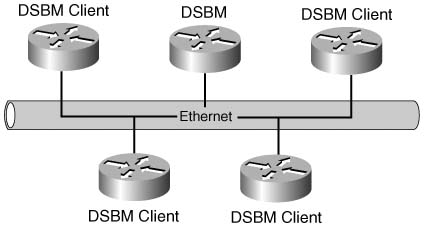
When a DSBM client sends or forwards an RSVP path message over an interface attached to a managed segment, it sends the path message to the DSBM of the segment rather than to the RSVP session destination address, as is done in conventional RSVP processing. As part of its message-processing procedure, the DSBM builds and maintains a path state for the session and notes the previous Layer 2 or Layer 3 hop from which it received the path message. After processing the path message, the DSBM forwards it toward its destination address.
The DSBM receives the RSVP resv message and processes it in a manner similar to how RSVP handles reservation request processing, basing the outcome on available bandwidth. The procedure is as follows:
![]() If it cannot grant the request because of lack of resources, the DSBM returns a resverror message to the requester.
If it cannot grant the request because of lack of resources, the DSBM returns a resverror message to the requester.
![]() If sufficient resources are available and the DSBM can grant the reservation request, it forwards the resv message toward the previous hops using the local path state for the session.
If sufficient resources are available and the DSBM can grant the reservation request, it forwards the resv message toward the previous hops using the local path state for the session.
The following three tasks are performed on a gateway to originate or terminate voice traffic using RSVP:
1. Turn on the synchronization feature between RSVP and H.323. This is a global command and is turned on by default when Cisco IOS Release 12.1(5)T or later is loaded.
2. Configure RSVP on both the originating and terminating sides of the VoIP dial peers. Configure both the requested QoS (req-qos) and the acceptable QoS (acc-qos) commands. The guaranteed-delay option must be chosen for RSVP to act as a CAC mechanism. Other combinations of parameters may lead to a reservation, but not offer CAC.
3. Enable RSVP and specify the maximum bandwidth on the interfaces that the call will traverse.
Table C-22 lists the commands used to define and enable RSVP.
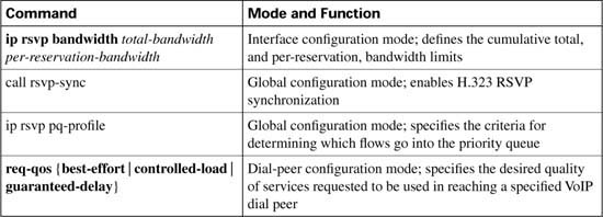

Example C-17 demonstrates the configuration required to enable RSVP with LLQ.
Example C-17 Enabling RSVP with LLQ
!
!RSVP classification default profile for Cisco VoIP packets
ip rsvp bandwidth 200 25
interface serial 0/0
service-policy output LLQ-policy
!
voice-port 1/0:0
!
dial-peer voice 100 pots
destination-pattern 2......
port 1/0:0
!
dial-peer voice 300 voip
destination-pattern 3......
session target ipv4:10.10.2.2
!Configures RSVP CAC for voice calls using the dial peer.
acc-qos guaranteed-delay
In the example, the call rsvp-sync command enables synchronization of H.323 and RSVP, which allows new call requests to reserve bandwidth using RSPV. The ip rsvp pq-profile command tells IOS to classify voice packets into a low-latency queue priority queue, assuming LLQ is configured on the same interface as RSVP. On interface serial 0/0, a service-policy command enables a policy map that defines LLQ, and the ip rsvp bandwidth command reserves a total of 200 kbps, with a per-reservation limit of 25 kbps. The req-qos and acc-qos commands tell IOS to make RSVP reservation requests when new call requests have been made.
Although RSVP does support reservations for voice traffic with H.323 sync, IOS does of course support RSVP independent of voice traffic. To support data traffic, LLQ may not even be needed.
Example C-18 demonstrates the configuration required to enable RSVP on a PPP interface, but with WFQ used rather than LLQ.
Example C-18 Enabling RSVP on a PPP Interface
bandwidth 1536
ip address 10.10.1.1 255.255.255.0
encapsulation ppp
!Enables WFQ as the basic queueing method.
fair-queue 64 256 36
!Enables RSVP on the interface.
You can also configure RSVP along with traffic shaping. RSVP can reserve bandwidth inside shaping queues. In Example C-19, the configuration shows RSVP enabled with Frame Relay traffic shaping (FRTS). The ip rsvp bandwidth command in this case is a subinterface subcommand, essentially reserving bandwidth inside the FRTS queues for each virtual circuit on that subinterface.
Example C-19 Enabling RSVP on a Frame Relay Interface
bandwidth 1536
encapsulation frame-relay
no fair-queue
frame-relay traffic-shaping
!
interface Serial0/0.2 point-to-point
ip address 10.10.2.2 255.255.255.0
frame-relay interface-dlci 17
class VoIPoFR
!Enables RSVP on the subinterface.
no frame-relay adaptive-shaping
frame-relay cir 128000
frame-relay bc 1280
frame-relay mincir 128000
!Enables WFQ as the basic queueing method.
frameframe-relay fair-queue
frame-relay fragment 160
Finally, Example C-20 shows RSVP and SBM enabled on Ethernet interface 2. After RSVP is enabled, the interface is configured as a DSBM and SBM candidate with a priority of 100. The configured SBM priority is higher than the default of 64, making the interface a good contender for DSBM status. The maximum configurable priority value is 128, however, so another interface configured with a higher priority could win the election and become the DSBM.
Table C-23 lists the commands used to enable and define the DSBM in Example C-20, which also shows the example SBM configuration.
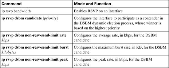
Example C-20 Enabling DSBM on an Ethernet Interface
ip address 145.2.2.150 255.255.255.0
no ip directed-broadcast
ip pim sparse-dense-mode
no ip mroute-cache
media-type 10BaseT
ip rsvp dsbm candidate 100
ip rsvp dsbm non-resv-send-limit rate 500
ip rsvp dsbm non-resv-send-limit burst 1000
ip rsvp dsbm non-resv-send-limit peak 500
This section covers a few details about the commands used to troubleshoot RSVP installations. Table C-24 lists other RSVP commands that can be useful in monitoring and troubleshooting RSVP.


Verifying synchronization is the first step in troubleshooting RSVP. Without synchronization, RSVP has no means to prevent an H.323 gateway from moving into the alerting state and consuming resources that may not be available. To verify synchronization, use the show call rsvp-sync conf command.
Example C-21 shows the output from the show call rsvp-sync conf command.
Example C-21 The show call rsvp-sync Command
VoIP QoS: RSVP/Voice Signaling Synchronization config:
Overture Synchronization is ON
Reservation Timer is set to 10 seconds
This output tells you that synchronization is enabled and the reservation timer will wait a maximum of 10 seconds for a reservation response.
To display statistics for calls that have attempted RSVP reservation, use the show call rsvp-sync stats command.
Example C-22 shows a sample output from the show call rsvp-sync stats command.
Example C-22 The show call rsvp-sync stats Command Output
VoIP QoS:Statistics Information:
Number of calls for which Reservation Success was notified : 0
Total Number of RESV Errors encountered : 0
Total Number of Reservation Timeouts encountered : 0
The show call rsvp-sync stats command offers a quick glance at reservation successes and failures on the router. A high number of errors or timeouts may indicate a network or configuration issue.
You can use the show ip rsvp installed command to display information about local interfaces configured for RSVP and the current reservations on the interfaces. In Example C-23, the show ip rsvp installed command shows that Ethernet interface 2/1 has four reservations but serial interface 3/0 has none.
Example C-23 The show ip rsvp installed Command
RSVP:Ethernet2/1
BPS To From Protoc DPort Sport Weight Conversation
44K 145.20.0.202 145.10.0.201 UDP 1001 1001 13 266
98K 145.20.0.202 145.10.0.201 UDP 1002 1002 6 265
1K 145.20.0.202 145.10.0.201 UDP 10 10 0 264
Router#
The current amount of reserved bandwidth for this interface is 187 kbps, as shown in the following:
With this information, you have the ability to compare the actual bandwidth reserved versus the maximum bandwidth configured on Ethernet 2/1 using the ip rsvp bandwidth command. Reserved bandwidth approaching the maximum can result in RSVP rejections.
You can obtain more detail about current reservations with the show ip rsvp installed detail command. Example C-24 shows an output of this command.
Example C-24 Sample show ip rsvp installed detail Command Output
RSVP:Ethernet2/1 has the following installed reservations
RSVP Reservation. Destination is 145.20.0.202, Source is 145.10.0.201,
Protocol is UDP, Destination port is 1000, Source port is 1000
Reserved bandwidth:44K bits/sec, Maximum burst:1K bytes, Peak rate:44K bits/sec
Resource provider for this flow:
WFQ on hw idb Se3/0: PRIORITY queue 264. Weight:0, BW 44 kbps
Conversation supports 1 reservations
Data given reserved service:316 packets (15800 bytes)
Data given best-effort service:0 packets (0 bytes)
Reserved traffic classified for 104 seconds
Long-term average bitrate (bits/sec):1212 reserved, 0M best-effort
RSVP Reservation. Destination is 145.20.0.202, Source is 145.10.0.201,
Protocol is UDP, Destination port is 1001, Source port is 1001
Reserved bandwidth:44K bits/sec, Maximum burst:3K bytes, Peak rate:44K bits/sec
Resource provider for this flow:
WFQ on hw idb Se3/0: RESERVED queue 266. Weight:13, BW 44 kbps
Conversation supports 1 reservations
Data given reserved service:9 packets (450 bytes)
Data given best-effort service:0 packets (0 bytes)
Reserved traffic classified for 107 seconds
Long-term average bitrate (bits/sec):33 reserved, 0M best-effort
RSVP Reservation. Destination is 145.20.0.202, Source is 145.10.0.201,
Protocol is UDP, Destination port is 1002, Source port is 1002
Router#
In this example, the reservation on Ethernet 2/1 has met the criteria of the voice-like profile and has been admitted into the priority queue. (A weight of 0 identifies the flows that have matched the voice-like profile.) The reservation on Serial 3/0 has not met the criteria of the voice-like profile and so has been admitted to a reserved WFQ.
Remember the following factors regarding the use of RSVP as a CAC mechanism:
![]() In current Cisco IOS Software, H.323 synchronization is initiated by default.
In current Cisco IOS Software, H.323 synchronization is initiated by default.
![]() RSVP packets (path and resv) travel as best-effort traffic.
RSVP packets (path and resv) travel as best-effort traffic.
![]() WFQ must be enabled on an interface/PVC as a basis for LLQ.
WFQ must be enabled on an interface/PVC as a basis for LLQ.
RSVP is a true end-to-end CAC mechanism only if configured on every interface that a call traverses.
For the unique capability to serve as both an end-to-end CAC mechanisms, and to guarantee the QoS for the entire duration of the call, RSVP does incur some “costs” on the network, as follows:
![]() Signaling (messaging and processing).
Signaling (messaging and processing).
![]() Per flow state (memory).
Per flow state (memory).
![]() Postdial delays.
Postdial delays.
![]() RSVP does not provide for call redirection after call setup if a link in the network should fail. Another mechanism, such as dial-peer preferences, must be configured to serve this function.
RSVP does not provide for call redirection after call setup if a link in the network should fail. Another mechanism, such as dial-peer preferences, must be configured to serve this function.
![]() RSVP is not yet supported on the Cisco IP Phones.
RSVP is not yet supported on the Cisco IP Phones.
Table C-25 evaluates the RSVP mechanism against the CAC evaluation criteria described earlier in this chapter.
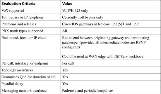
The “Foundation Summary” is a collection of tables and figures that provide a convenient review of many key concepts in this chapter. For those of you already comfortable with the topics in this chapter, this summary could help you recall a few details. For those of you who just read this chapter, this review should help solidify some key facts. For any of you doing your final prep before the exam, these tables and figures are a convenient way to review the day before the exam.
Figure C-35 shows the effect of a VoIP network without the use of CAC.

Figure C-36 shows how CAC can be used in a legacy VoIP network to redirect a call to the PSTN in the even that sufficient resources are not available to carry the call on the data network.
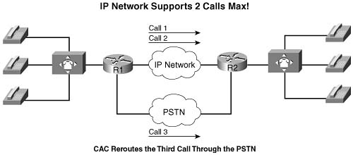
Figure C-37 shows how CAC can be used in an IP telephony network to redirect a call to the PSTN in the event that sufficient resources are not available to carry the call on the data network.

Table C-26 illustrates a few of the possible G.711 and G.729 bandwidth requirements.

*For DQOS test takers: These numbers are extracted from the DQOS course, so you can study those numbers. Note, however, that the numbers in the table and following examples do not include the L2 trailer overhead.
Figure C-38 illustrates the packet structure of the layer 2 and IP/UDP/RTP headers and the payload for a voice packet.

Table C-27 describes the criteria that is used to evaluate the different CAC tools.

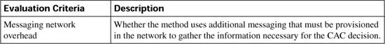
Figure C-39 illustrates a network using physical DS0 limitation to provide CAC.

Table C-28 evaluates the physical DS0 limitation mechanism against the CAC evaluation criteria described earlier in this chapter.

Figure C-40 shows a typical VoIP network that can use the max-conn command to limit the number of calls between locations.
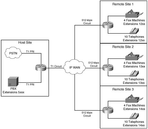
Table C-29 evaluates the Max-Connections mechanism against the CAC evaluation criteria described earlier in this chapter.
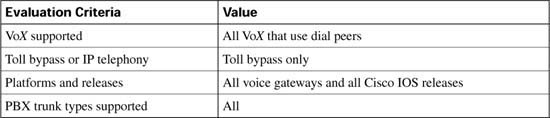
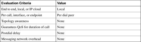
Figure C-41 shows a typical VoFR network that can use the frame-relay voice-bandwidth command to limit the number of calls between locations.

Table C-30 evaluates the VoFR Voice-Bandwidth mechanism against the CAC evaluation criteria described earlier in this chapter.


Figure C-42 shows a VoIP network using the connection trunk command to emulate a circuit switched network.

Table C-31 evaluates the trunk conditioning mechanism against the CAC evaluation criteria described earlier in this chapter.
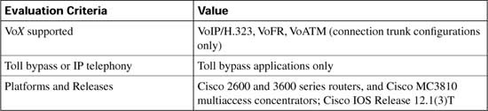
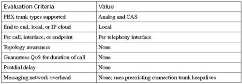
Figure C-43 shows a VoIP network using Local Voice Busyout to provide CAC.

Table C-32 evaluates the Local Voice Busyout mechanism against the CAC evaluation criteria described earlier in this chapter.
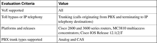
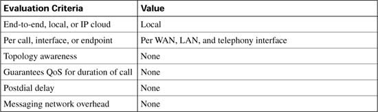
Figure C-44 shows a VoIP network using Advanced Voice Busyout to provide CAC.
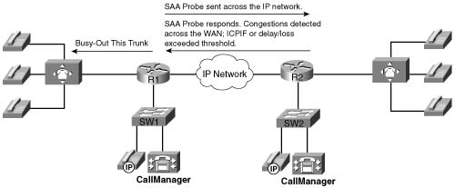
Table C-33 evaluates the AVBO mechanism against the CAC evaluation criteria described earlier in this chapter.
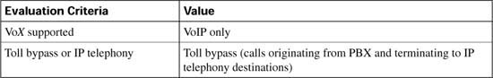
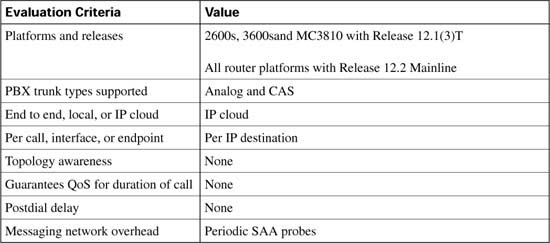
Figure C-45 shows a VoIP network using PSTN fallback to provide CAC.

Table C-34 lists the options and default values of the call fallback command.

Figure C-46 illustrates the call setup process for PSTN fallback.

Table C-35 evaluates the PSTN fallback mechanism against the CAC evaluation criteria described earlier in this chapter.


Figure C-47 illustrates how a CAC decision is made with resource availability indication (RAI).
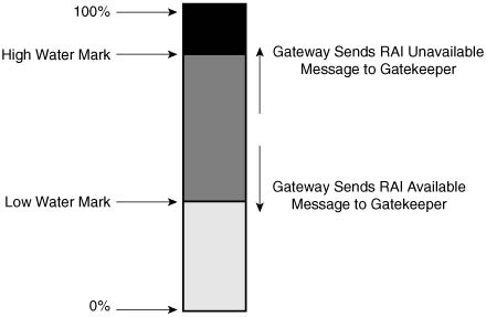
Table C-36 evaluates the RAI mechanism against the CAC evaluation criteria described earlier in this chapter.

Figure C-48 illustrates a typical CallManager centralized call-processing model using locations to provide CAC.
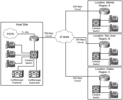
Table C-37 shows the amount of bandwidth that will be subtracted, per call, from the total allotted bandwidth for a configured region.
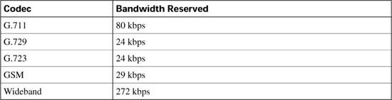
Table C-38 evaluates location-based CAC against the CAC evaluation criteria described earlier in this chapter.

Figure C-49 shows a single-zone gatekeeper-controlled VoIP network with two gateways that illustrates gatekeeper CAC in its simplest form.

Figure C-50 shows a more complex enterprise multizone multigatekeeper-controlled VoIP network.

Figure C-51 shows a pair of CallManager clusters using a gatekeeper to provide CAC between the clusters.

Tables C-39 and C-40 list the gatekeeper commands and options used to configure gatekeeper zone bandwidth.

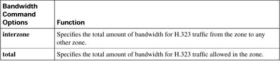
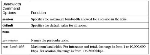
Table C-41 evaluates the gatekeeper zone bandwidth mechanism against the CAC evaluation criteria described earlier in this chapter.

Figure C-52 shows the flow of RSVP path and resv messages through the network.

Figure C-53 shows a call flow of the H.323 call setup messages and the RSVP reservation messages.

Table C-42 describes the available options for the acc-qos and req-qos commands.

This table was derived from the following: www.cisco.com/en/US/partner/products/sw/iosswrel/ps1834/products_feature_guide09186a008008045c.html.
Table C-18 summarizes the results of nine call setup scenarios based on the QoS levels that can be configured in the VoIP dial peers at the originating and terminating gateways.
Figure C-54 illustrates how RSVP uses the priority queue in LLQ for packets matching the voice-like profile.

Table C-43 summarizes the bandwidth RSVP allocates for calls using different Cisco IOS gateway codecs.

Table C-44 lists the commands used to define and enable RSVP.
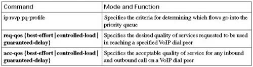
Figure C-55 shows a managed segment in a Layer 2 domain that interconnects a group of routers.
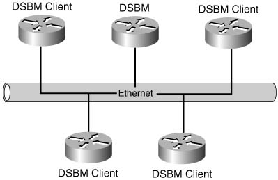
Table C-45 lists the commands used to enable and define the DSBM in Example C-18.
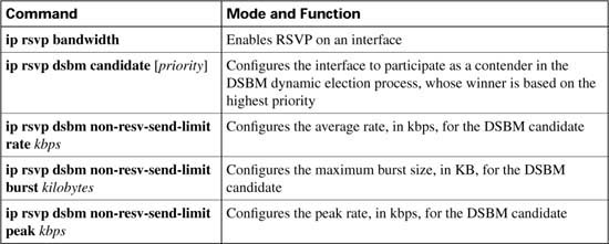
Table C-46 lists other RSVP commands that can be useful in monitoring and troubleshooting RSVP.

Table C-47 evaluates the RSVP mechanism against the CAC evaluation criteria described earlier in this chapter.

There is little overlap between local CAC mechanisms and those that look ahead to the rest of the network to determine nonlocal conditions. It is easy to understand why the distinct local and nonlocal mechanisms are useful. However, there is considerable overlap between the measurement techniques and the resource reservation techniques of the two nonlocal, lookahead CAC mechanisms. For this reason, there is debate over which is the better method.
Table C-48 compares the strengths and weaknesses of the measurement-based and resource-based CAC mechanisms. With this information, you can determine the best method for your individual network.


Table C-49 summarizes the 11 different voice CAC mechanisms that have been discussed in chapter. It also lists the first Cisco IOS release in which the feature became available.


Table C-50 summarizes the voice technologies supported by the CAC methods discussed in this chapter.