
Chapter 4. Onboarding and Provisioning
This chapter covers the following topics:
Configuration Templates: In this section, we discuss various template types, including CLI, device, and feature templates. Design and scaling techniques with templates are discussed in this section as well.
Developing and Deploying Templates: This section provides step-by-step instructions on how to build and deploy device and feature templates.
Onboarding Devices: Onboarding of devices with manual bootstrapping as well as automatic provisioning with techniques such as Plug and Play (PNP) and Zero Touch Provisioning (ZTP) are discussed in this section.
Current methods for managing configurations on network devices pose a lot of challenges. These challenges include version control, human error, and scaling considerations when deploying to a large number of devices. Traditionally, network engineers will make individual changes to various network devices via the command line interface (CLI). As networks grow, these configurations are often shared or piecemealed with other network devices (such as QoS or Routing Protocol configurations). Using QoS as an example, many questions must be answered before deployment and, depending on the device, different options exist on how to modify the configuration. Is it MLS queuing or MQC queueing? What hardware platform is it? How many queues has the service provider provided? What DSCP values are you using? This creates a lot of complexity when managing configuration options. In a perfect world, all of our devices and configurations would be standardized across locations. But this isn’t realistic due to a multitude of reasons (such as different providers, hardware upgrade cycles, business needs, and so on). As the network grows, the disparity among network devices and network functions makes operations and troubleshooting even more difficult. To compound this issue, network configurations tend to persist as devices are upgraded and replaced. As such, the original intent of the network configuration gets lost as the IT staff turns over or other factors change. In most cases, network device configurations are rarely revisited for cleanup. One last issue to confront is version control. Network administrators tend to make configuration changes on the fly wherein the previous config gets lost. Version control is important, especially when there are outages. Having a working configuration to roll back to can save a lot of headache. Oftentimes, outages don’t always get noticed immediately after the change. With no version control or change management in place, rolling back to the last-known configuration becomes difficult, as the previous configuration was not tracked.
With the Cisco SD-WAN solution, configuration management is maintained via a robust templating engine that supports automatic rollback. Templates are all built around your intent wherein the network administrator doesn’t need to be concerned with what type of device this configuration is being applied to or the specific configuration options available in that version of the operating system. Templates are built in a modular fashion where they can be reused across differing device types. This allows the network administrator to quickly roll out configurations or changes at a wide scale while also ensuring the syntax is correct and is supported on any platform. Another feature of the Cisco SD-WAN solution is automatic rollback. If a configuration option gets applied to a device and it cuts off the device’s ability to be managed by vManage, then the device will automatically roll back and allow the network engineer to correct the issue.
With today’s networks getting larger and larger, the need to reduce provisioning and onboarding of devices needs to decrease. For example, to onboard a network device at a branch, the following approach is usually taken:
The device ships from manufacturing to IT staff.
The network administrator applies configuration to the device.
The IT staff drives or ships the device to the location and physically installs it.
This process is expensive for the organization, especially when looking at performing these actions across thousands of devices. If there are issues, and the device won’t connect to the network, this adds further delay and operational expense as IT teams work to troubleshoot. In some cases, these installs are performed remotely. While this reduces the cost of traveling, it can create a lot of frustration if and when an issue arises. With a lack of local IT support at the site, network administrators often end up having to rely on non-IT staff to perform operations on the device. This puts a lot of faith in the remote staff and potentially takes them away from their day job. The Cisco SD-WAN solution simplifies onboarding and provisioning of a device. WAN Edge devices support mechanisms such as PNP and ZTP to automatically bring the device online and into the fabric. These onboarding solutions work by allowing the network administrator to pre-configure the device within the vManage controller. Once the vManage controller sees the device, it will automatically apply the specified configuration. WAN Edges can be shipped directly to the remote location and don’t require initial configuration from IT staff. Once physically installed at the remote site, the device will automatically locate the vManage controller and begin the provisioning process. By reducing the time to bring up remote sites, the IT staff can bring more devices online more quickly and with fewer errors. This time-savings reduces operational cost, which allows IT staff to focus on bringing additional capabilities to the business.
Configuration Templates
Configurations can be applied one of two ways in the Cisco SD-WAN solution. The network administrator can either apply configuration manually via the CLI (that is, by using SSH to connect to the device or by connecting via the console port) or by using the vManage GUI. Using the vManage GUI is the preferred mechanism, as it is less error-prone and has support for automatic recovery. Configurations provisioned on vManage can be applied to both WAN Edges and vSmart controllers. When vManage is responsible for applying the configuration, it is the single source of truth, and changes can only be applied via vManage.
Note
To apply centralized policy to the vSmart controller, vSmart needs to be under the control of the vManage controller. When a component is managed by vManage, the administrator will be unable to make changes locally to the device.
When applying configuration to WAN Edge devices or controllers using the vManage GUI, a network administrator will apply a device template to a single device or multiple devices. These device templates (see Figure 4-1) can either be CLI based or feature template based. When a CLI template is being built, the whole configuration must be in the template (not just specific configuration snippets) as opposed to feature templates. Feature templates can be thought of as building blocks wherein each block is a specific technology feature. Feature templates define what specific feature or technology you want enabled or configured, such as routing protocols, interface parameters, and Overlay Management Protocol (OMP). Feature templates can be reused between multiple device templates, and it is this flexibility that brings greater scale to the solution (and why feature templates are the recommended way of configuring devices). Feature templates can be device type agnostic as well. The network administrator needs only to be concerned with the intent of the configuration. When vManage applies the configuration to a specific device, be it a Cisco IOS-based device or a Viptela OS device, vManage will apply the correct device syntax.

Figure 4-1 Device Templates
Device templates are a collection of feature templates and can only be applied to specific device types. For this reason, you may have multiple device templates for the same model of hardware, depending on the device’s location, connectivity options, or what role it is playing in the network. A device template can’t be shared across different device types, but feature templates can be used across multiple different device types. As illustrated in Figure 4-2, there are four main parts or groups of a device template:
Basic Information: This section includes items such as System, Logging, AAA, BFD, and OMP feature templates.
Transport and Management VPN: This section has templates for configuration of VPN 0 and VPN 512 (such as underlay routing protocol configuration and interface configuration).
Service VPN: This section is where service VPNs or LAN-facing template configurations will exist. This is where BGP, OSPF, and interface parameters are configured.
Additional Templates: This section is for local policies, security policies, SNMP configuration templates, and so on.
Feature templates make configuration options extremely flexible. For example, feature templates provide the option to define variables for configuration parameters. This allows you to reduce the number of templates required in your deployment, yet make it much more modular. To further this example, suppose you have MPLS transports that use different physical interface numbers: Gi0/0, Gi0/1, Gi0/2, and so on. Initially, the thought may be to build a feature template for each physical interface with a different IP address. This would result in three different templates. By using variables for the physical interface and IP address options, the administrator can condense this down to one feature template that can be used across all device templates.
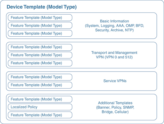
Figure 4-2 Device Template Structure
Figure 4-3 shows how variables can be utilized to control template sprawl. In this example, we have nine different interface templates, depending on if the IP address is assigned via DHCP and what interface is used. By using variables, the network administrator can reduce this down to three different feature templates.
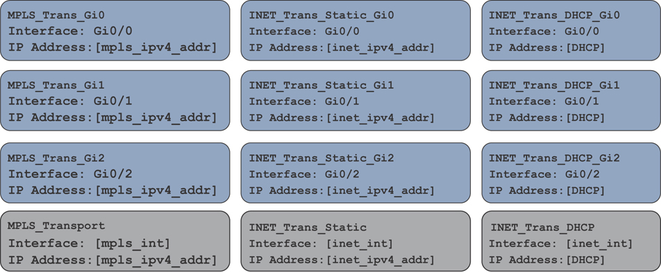
Figure 4-3 Controlling Template Sprawl
Three types of values can be defined in a template:
Default: Factory default value. Default values cannot be changed. An example might be using the default BFD timers.
Global: Values set here will be the same wherever this configuration option is used. An example could be SNMP community strings that you want globally applied to all devices utilizing this template. The beauty of this is that, later on (if there needs to be a change to these values), you just update the feature template global option and it updates every device template that is using this feature template.
Device Specific: The value is set via a user-defined variable. This is the preceding referenced example with interface names. The values to these variables are set when the device template is attached to a specific device.
Looking at Figure 4-4, the network administrator can see how these referenced values can be utilized. Some template options might not have all three of these options, depending what is being configured. For example, a BGP AS number won’t have a default value.
A large number of feature template options can be configured. Here are some common feature templates:
System: Configure basic system information such as System IP, Site ID, and Hostname.
BFD: Adjust BFD timers and app-route multipliers for each transport or color. BFD timers are used for App-Aware Routing.
OMP: Change graceful restart timers or control redistribution from other routing protocols into OMP.
Security: Change IPsec security settings such as anti-replay, authentication, and encryption.
VPN: Define a service VPN, routing protocol redistribution, or static routing.
BGP: Configuration of BGP in a VPN or VRF.
OSPF: Configuration of OSPF in a VPN or VRF.
VPN Interface: Define an interface that is part of a service VPN or VRF. Common configuration options here include IP Address, QoS, ACLs, and NAT.
As the feature templates are defined, they can be referenced via a device template. After the device template is created, it can be applied to a specific device or a group of devices. Remember, device templates can only be built for a specific device type. If there are any variables defined in the feature template, at the time the device template is attached, these values will need to be populated. Once these values are defined, a configuration syntax check is done in vManage. If successful, the configuration is then pushed to the device. Feature template variable values can be populated either within the vManage template attachment workflow or by using a CSV file. Populating feature template variables via CSV allows an administrator to quickly provision many devices all at once. If, at the time the configuration is pushed to the device, the WAN Edge loses control plane connectivity to the vManage controller, the WAN Edge will start a rollback timer of 5 minutes. If it doesn’t re-establish connectivity within that 5 minutes, it will roll back its configuration and reconnect to vManage using the last known-good configuration. At this time, the network administrator will see that the device is out of sync and can correct the issue.

Figure 4-4 Setting Variables
If the need arises to change these values after the device template has been applied, an option exists to change these values on a device-by-device basis. If any changes are made to a feature template or device template, vManage will immediately push the updated configuration to all devices utilizing that template. An example of this could be changing the IP address or the username and password of the device.
Developing and Deploying Templates
Template configuration and creation is performed in the vManage GUI. After initial installation of vManage, some default templates are created. These templates can be used as a starting point, or new ones can be created. To create templates, the network administrator will navigate to Configuration > Templates.
Step 1. Go to the configuration section for templates, as illustrated in Figure 4-5.
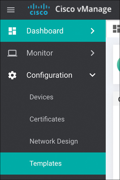
Figure 4-5 Accessing the Template Configuration Interface
Step 2. Once at the template configuration window, you’re presented with the option to configure device templates or feature templates, as illustrated in Figure 4-6.
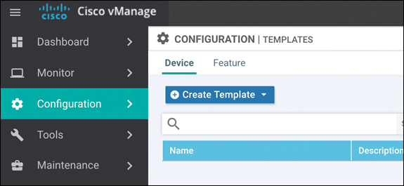
Figure 4-6 Configuration Templates Window
Step 3. The next step is to begin creating feature templates. Select Feature (tab) > Add Template. Select the devices that this template will apply to and select the type of template, as illustrated in Figure 4-7.

Figure 4-7 Template Configuration: Device Selection Window
Step 4. After selecting the type of feature template you wish to configure, you now have the ability to start setting values, as illustrated in Figure 4-8. These values can be either variables, global parameters, or the default parameter. After the configuration options have been set and the template has been named, click Save.

Figure 4-8 Template Configuration: Setting Configuration Values
Step 5. Now that the feature templates have been created, they need to be attached to their respective device templates. Click Device (tab) followed by Create Template. After you click Create Template, the option to create a CLI-based template or a feature-based template is provided. Select From Feature Template, as illustrated in Figure 4-9.
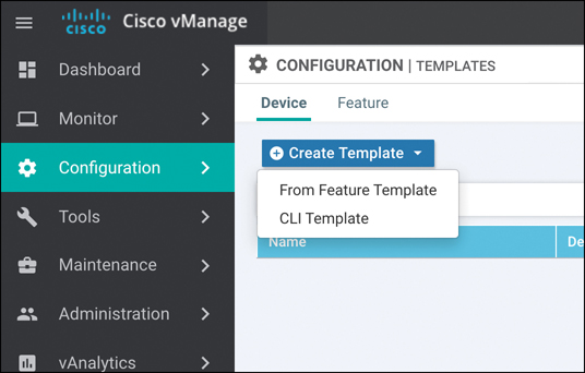
Figure 4-9 Template Configuration: Device Template Selection
Step 6. After selecting a feature-based template, you need to select the device model this template will apply to as well as provide a name for the template, as illustrated in Figure 4-10. Once this is done, you have the ability to start selecting what feature templates to use. In this example, we’ll select the BFD template we created in the previous example. Once done, select Save.

Figure 4-10 Template Configuration: Device Template Feature Selection
Step 7. Now that the device template is created, you can attach it to devices. From the Device Templates page, click the ellipses next to the template you wish to attach. Select the option to Attach Devices, as illustrated in Figure 4-11.
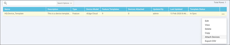
Figure 4-11 Attaching a Template to a Device
Step 8. From here, you can select the devices to apply the configurations to, as illustrated in Figure 4-12. Once you select the device, you have the option to populate any variables.

Figure 4-12 Device Selection Window
Onboarding Devices
For a WAN Edge to join the SD-WAN fabric, the WAN Edge first needs to establish connectivity to the vBond controller. The vBond controller facilitates discovery of the vManage and vSmart controllers. As the WAN Edge establishes connectivity to each of these controllers, mutual authentication will occur. After the WAN Edge has authenticated to the controller components in the overlay, the device will receive its full configuration from vManage. There are two methods to bootstrap a device with initial configuration so that it can reach vBond. The less preferred, and more obvious, method is to manually apply minimal configuration to the device. The second method is automatically discovering the network using Zero Touch Provisioning (ZTP) or Plug and Play (PNP). If the device is running Viptela OS, it will use ZTP. If the device is an IOS XE-based device, then Plug and Play is utilized. The general process of ZTP and PNP is similar. The following sections elaborate on each process.
Manual Bootstrapping of a WAN Edge
To manually bootstrap a WAN Edge device, the network administrator will begin by applying a minimal configuration to the device. This includes IP addressing, vBond addressing (either DNS hostname or IP), and system identification information. This information is used to establish initial connectivity and authentication. The process to manually bootstrap a device is as follows:
Step 1. Configure an IP address and default gateway. If DHCP is available, this can be used to assign the IP and gateway automatically.
Step 2. Configure the vBond IP or hostname. If you are using a hostname, then a DNS server address must be provided, and the device must have reachability from VPN 0.
Step 3. Configure device identification information, including the system IP, site ID, and organization name.
Examples 4-1 and 4-2 show the minimal configuration for Viptela OS and SD-WAN IOS-XE devices.
Example 4-1 Minimal Configuration for a Viptela OS–based Device
vEdge# config
vEdge(config)#
vEdge(config)# system host-name hostname
vEdge(config-system)#system-ip ip-address
vEdge(config-system)# site-id site-id
vEdge(config-system)# organization-name organization-name
vEdge(config-system)# vbond (dns-name | ip-address)
vEdge(config)# vpn 0
vEdge(config-vpn-0)# interface interface-name
vEdge(config-interface)# (ip dhcp-client | ip address prefix/length)
vEdge(config-interface)# no shutdown
vEdge(config-interface)# tunnel-interface
vEdge(config-tunnel-interface)# color color
vEdge(config-vpn-0)# ip route 0.0.0.0/0 next-hop
vEdge(config)# commit and-quit
Example 4-2 Minimal Configuration for an IOS-XE based Device
Device# config-transaction
Device(config)#
Device(config)# system host-name  hostname
Device(config-system)# system-ip  ip-address
Device(config-system)# site-id site-id
Device(config-system)# vbond (dns-name | ip-address)
Device(config-system)# organization-name name
Device(config)# interface Tunnel #
Device(config-if)# ip unnumbered wan-physical-interface
Device(config-if)# tunnel source wan-physical-interface
Device(config-if)# tunnel mode sdwan
Device(config)# interface GigabitEthernet  #
Device(config)# ip address  ip-address mask
Device(config)# no shut
Device(config)# exit
Device(config)# sdwan
Device(config-sdwan)# interface  WAN-interface-name
Device(config-interface-interface-name)# tunnel-interface
Device(config-tunnel-interface)# color color
Device(config-tunnel-interface)# encapsulation  ipsec
Device(config)# ip route 0.0.0.0 0.0.0.0 next-hop-ip-address
Device(config)# ip domain lookup
Device(config)# ip name-server dns-server-ip-address
Device(config)# commit
Device# exit
Automatic Provisioning with PNP or ZTP
The second method of provisioning devices allows the network administrator to automatically bring the devices online with minimal effort and involvement. Once powered on, the default configuration on the device tries to receive an IP address via DHCP. Once the device has an IP address, it will reach out to the automatic provisioning server (hosted by Cisco) and learn about the organization’s vBond. At this point, the process is exactly the same as the manual bootstrapping process. The device will connect and authenticate to the vBond, learn of vManage and vSmart, and then receive its configuration.
Note
The automatic provisioning servers are managed via the Plug and Play portal at http://software.cisco.com. As devices are purchased from Cisco, their serial numbers will be populated here. vManage can also be configured to synchronize with this portal to automatically populate the organization’s devices into vManage.
Before the automatic provisioning process can be initiated, the network administrator needs to attach a device template in vManage for the respective device. The device template must have the system IP and site ID for the device populated as well. If none of this is completed, the process will not succeed. Once vManage sees the device for the first time, it will push the template that is assigned to the matching serial number of the device performing ZTP or PNP.
As briefly described previously, depending on the type of device, the process is slightly different. If the device is a Viptela OS–based device, ZTP will be used. Once the device boots up, it will start the process to receive an IP address and DNS server via DHCP. After this succeeds, it will try to resolve ztp.viptela.com. If successful, the device will connect to the ZTP server and (after the ZTP server verifies what organization the device belongs to) it will redirect the device to the correct vBond for the organization. The ZTP server is able to verify which organization the device belongs to by checking the serial number of the device against its ZTP entries database. Once it’s connected to the vBond, the normal process continues. For ZTP to function, two things must happen: DHCP must be available on the WAN (VPN 0) facing interface and the device must be able to resolve ztp.viptela.com. Each Viptela OS–based device has specific interfaces that are to be used for ZTP. Refer to the latest product documentation to determine which interface should be used. Figure 4-13 outlines the process, described in further detail in the list that follows.

Figure 4-13 Zero Touch Provisioning Workflow
The vEdge device queries ztp.viptela.com. The ZTP server verifies that the device’s serial number and organization exist in the ZTP database.
If the vEdge performing the ZTP process exists in the ZTP database, the ZTP server responds telling the vEdge what the connectivity information is for the organization’s vBond controller.
The vEdge then connects to the corporate vBond and goes through the authentication process. If successful, the vBond will tell the vEdge about the vSmart and vManage controllers in the overlay. At this point, vManage will push the necessary configuration to the device.
For Cisco IOS-XE based devices, a slightly different method is used instead of ZTP. PNP operates almost identically to ZTP, except instead of building a DTLS tunnel to the PNP server (devicehelper.cisco.com), the device will communicate to the server via HTTPS. After the PNP server validates the device, it will redirect the IOS-XE based WAN Edge to the relevant vBond for the organization. IOS-XE based devices have the same requirements as ZTP devices in that they must get an IP address and DNS server via DHCP and be able to resolve devicehelper.cisco.com. Figure 4-14 outlines the process of onboarding a device with PNP.
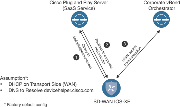
Figure 4-14 Plug and Play Workflow
Summary
With the Cisco SD-WAN solution, network configurations are handled with ease via a powerful template engine. Feature templates can be utilized to achieve modularity of configuration that can be reused across various platforms. All of these feature templates are used to form a device template. By using variables within these templates, the network administrator can support a large range of configuration requirements.
Provisioning of devices can occur with one of two methods: either manual or with an automatic process such as Plug and Play or Zero Touch Provisioning. With the manual method, the amount of configuration is very small. The device must have system IP, site ID, organization name, and IP address information. Once the device authenticates to the organization’s vBond, it will discover the rest of the controller elements, and vManage can push configuration down to the device. The second option involves using an automatic onboarding process. This process uses either ZTP or PNP, depending on if it’s a Viptela OS–based product or a Cisco IOS-based product. Once the device has gone through the automatic method and determined the vBond to use, the process works just the same as with the manual method. This allows the network administrator to deploy a large number devices quickly, even if they have different configuration options.
Review All Key Topics
Review the most important topics in the chapter, noted with the Key Topic icon in the outer margin of the page. Table 4-1 lists these key topics and the page numbers on which each is found.
Table 4-1 Key Topics
Key Topic Element |
Description |
Page |
|---|---|---|
Paragraphs |
Device templates are a collection of feature templates or a CLI template. These templates are what are applied to the device. |
93 |
Paragraph |
Feature templates make up the building blocks or configuration options for various features. These templates are selected from within the device template. Variables can be utilized to make these templates even more modular. |
94 |
Section |
Onboarding Devices Zero Touch Provisioning, or ZTP, is the automatic onboarding process used by Viptela OS–based devices. Connectivity to the ZTP server is established via DTLS tunnel. |
101 |
Section |
Automatic Provisioning with PNP or ZTP Just like ZTP, Plug and Play, or PNP, is an automatic process for onboarding Cisco IOS-XE based devices. PNP uses HTTPS to connect to the PNP server. |
103 |
Chapter Review Questions
1. What two methods can be used to construct device templates?
CLI
Feature templates
Directly on the device
Multiple CLI Templates
2. What are the three device value types that can be used with feature templates?
Global
Default
Automatic
Imported
Variables
3. Device templates support multiple different device types.
True
False
4. CLI templates can be used in a modular format and achieve the same flexibility of feature templates.
False
True
5. Which automatic provisioning method uses HTTPS for communication?
Plug and Play
Zero Touch Provisioning
NAT traversal
6. Which three things must a device have for automatic provisioning to be successful?
IP address and DNS server via DHCP
Be able to resolve ZTP/PNP domain name
Connectivity to ZTP or PNP server
IPsec tunnel
Connectivity to data center
References
Cisco SD-WAN Command Line Reference, https://www.cisco.com/c/en/us/td/docs/routers/sdwan/command/sdwan-cr-book.html
Cisco SD-WAN CVD – Certificate Deployment, https://www.cisco.com/c/dam/en/us/td/docs/solutions/CVD/SDWAN/CVD-SD-WAN-Design-2018OCT.pdf, October 2018