
Chapter 12. Cisco SD-WAN Design and Migration
This chapter covers the following topics:
Cisco SD-WAN Design Methodology: This section covers the methodology behind SD-WAN design across the enterprise.
Cisco SD-WAN Migration Preparation: This section of the chapter covers the recommended steps to prepare for migrating an enterprise to Cisco SD-WAN.
Cisco SD-WAN Data Center Design: This section of the chapter goes into detailed data center design options and migration techniques.
Cisco SD-WAN Branch Design: This section of the chapter goes into detailed branch design options and migration techniques.
Cisco SD-WAN Overlay and Underlay Integration: This section of the chapter discusses optimal connectivity methods between migrated and non-migrated sites.
Cisco SD-WAN Design Methodology
For most organizations, migrating to Cisco SD-WAN is done in a brownfield environment and is a rare opportunity to re-architect the entire wide area network—an opportunity that might only present itself every decade or so. The WAN is such a critical and sensitive component of a typical organization’s business that approvals for lengthy outages necessitated by pervasive design changes are a rarity. This means that it is common to see many years of incremental changes done by a multitude of individuals (with different skillsets and design methodologies) along with temporary fixes or adjustments that were never re-evaluated. Coupled with inconsistent configurations and connectivity models, this all results in complexities that, oftentimes, not a single person on staff may fully comprehend.
Designing your next-generation WAN is a golden opportunity to really dig deep into your WAN. You can learn how it operates, understand all the complexities and caveats that lie within, and propose a scalable, high-performing, easy-to-manage next-generation solution. It is crucial that the individuals leading the Cisco SD-WAN design and deployment dissect the existing WAN architecture in order to have a solid understanding of routing, topology, high availability, failover, and traffic flow patterns. This is in an effort to discover all the potential problems that may arise during migration. With this information on hand, you can utilize the incredibly comprehensive toolsets that are native to Cisco SD-WAN to effectively solve these problems intelligently and efficiently. During this process, the ultimate goal should be to remove unnecessary complexity, either through the evaluation of why that complexity existed initially and if it is still required or through replacing it with the intelligent application-aware and flexible fabric that Cisco SD-WAN offers.
The goal of this section is to present design recommendations garnered through years of Cisco SD-WAN implementation experience that will allow an organization to gracefully migrate to this new architecture while ensuring that the existing WAN is not disrupted. Ideally, the legacy WAN and the Cisco SD-WAN should be able to operate like ships in the night. An example of such a recommendation might be to selectively place Cisco SD-WAN hubs across your enterprise in order to act as transit points between migrated and non-migrated sites. Another such recommendation might be to provide high availability at branch sites through the use of Virtual Router Redundancy Protocol (VRRP) between an existing non-Cisco SD-WAN router and the new SD-WAN router.
Truthfully, there are many ways to migrate to Cisco SD-WAN—some better than others. In the end, however, everything always comes back to the fundamental routing and traffic engineering concepts we know and love today. Rest assured that Cisco SD-WAN is unparalleled in its support for comprehensive routing and traffic engineering toolsets, including best path manipulation options, advanced routing protocol features, filtering and tagging, and an overlay management protocol that provides traffic engineering flexibility like never before seen in the industry.
Cisco SD-WAN Migration Preparation
Preparing for Cisco SD-WAN migration can be thought of as one of the most important steps in the journey to Cisco SD-WAN enablement. Solid preparation will set an organization up for success during all stages of migration, including data center deployment, branch deployment, and policy configuration. Here are some of the most important preparations to make prior to beginning the migration:
Data center and branch site physical and logical diagramming: To have a good understanding of the existing architecture at data centers and branch sites, it is important to collect up-to-date physical and logical diagrams. This comes in handy to ensure there is sufficient power, cooling, rack space, and port density and to visualize how the Cisco SD-WAN routers will be connected to the existing network.
Collection of existing device configurations: Collecting and reviewing the existing device configurations ensures that all considerations have been made around Cisco SD-WAN feature support and enablement. You don’t want to realize, in the middle of a site turnup, that a specific feature you were using prior to the Cisco SD-WAN migration is not yet supported or that you have not made provisions to ensure that the feature would still function as designed after the migration.
Analysis of existing topology, routing, and traffic engineering: Having a good understanding of existing routing and traffic engineering in the network will allow you insert Cisco SD-WAN into the network with ease. It will allow you to determine if anything needs to be changed during the migration or if a specific consideration needs to be made to ensure that the same network behaviors exist post-migration. This might include topology design, data center affinity configuration, equal-cost multipath routing, high availability configuration, and failover behavior.
Bandwidth capacity planning: In many designs, the data center can become a hub either temporarily or permanently. For this reason, it is important to plan ahead to ensure that WAN bandwidth is sufficient pre- and post-migration.
Allocation of new physical and logical network resources: In most cases, there will be new Cisco SD-WAN routers added to the data centers in the environment. 1Gbps or 10Gbps connectivity will need to be provided for the LAN and WAN. New subnets and IP addresses will need to be cut for transit and management networking. Planning this out ahead of time will allow you to scale consistently and contiguously.
Configuration of new or existing network entities: Pre-stage the configuration required on new or existing network devices for a smooth deployment. This could include the configuration of a new VPN, VLANs, transit links, routing processes, prefix lists, route filters, autonomous systems, and so on.
Documentation of Cisco SD-WAN-specific configuration values: As mentioned in previous chapters, the Cisco SD-WAN fabric has many unique values that must be configured in order to build the secure extensible network. This includes values such as the system IP, site ID, encapsulation type, and transport color. It may also include other parameters such as TLOC priority, TLOC weight, upstream and downstream transport bandwidth, GPS coordinates, hostnames, DNS, management loopbacks, and more. Deployment is much smoother when all of these variables are predefined and well documented.
Cisco SD-WAN policy design and configuration: Cisco SD-WAN policy dictates the groups of interest (prefix-lists, site-lists, and so on), network topology, traffic engineering, overlay routing, Application-Aware Routing, security posture, quality of service classification, application visibility, and much more. Prior to migration, the Cisco SD-WAN policy should be fully thought out, predefined, configured, and activated so that sites rolling onto the fabric inherit the policy and adhere to it immediately. A well-constructed and executed policy will ensure that the migration is smooth and that post-migration performance is high.
Cisco SD-WAN device template configuration and attachment: One of the most powerful features of Cisco SD-WAN is templating. Device and feature templates allow for a modular and flexible configuration model that can be fully preconfigured and attached to Cisco SD-WAN routers before they even join the overlay. This allows you to pre-stage hundreds of remote sites with vManage, waiting and ready to push configuration as soon as the Zero Touch Provisioning process is initiated. Spend time prior to the deployment figuring out how these templates should be designed based on site structure and functionality, what configurations should be made as variables, and what those variable entries actually are.
Cisco SD-WAN Data Center Design
In nearly all cases, the data center is the first site to be migrated to Cisco SD-WAN. While there are many ways to design SD-WAN into the data center, the most commonly deployed and strongly recommended approach is to insert and run the solution in parallel with the existing WAN. This is accomplished by standing up Cisco SD-WAN routers alongside the current WAN Edge infrastructure (behind the Multiprotocol Label Switching [MPLS] CE/PE or Internet Edge routers) and providing the routers connectivity to WAN transports indirectly. This is especially true when an organization doesn’t have the luxury of providing the Cisco SD-WAN router dedicated circuits or handoffs for all the transports already in service. It is common to see new SD-WAN routers leveraging private connectivity through an existing MPLS CE/PE router and public connectivity through an existing secure Internet Edge firewall. Figure 12-1 depicts this architecture.
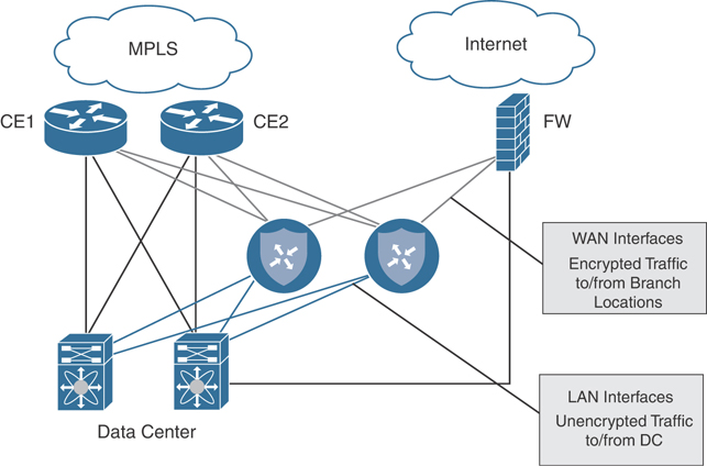
Figure 12-1 Data Center Dedicated Pod
This design allows the data center to act as a transit site for traffic between non-Cisco SD-WAN and Cisco SD-WAN sites and allows for a gradual migration of remote sites to Cisco SD-WAN without affecting the legacy network. This type of design also decouples and removes fate sharing between non-migrated and migrated sites, as they are landing on separate WAN Edges in the data center with distinct domains for routing and control. This same design can be used when migrating from legacy overlay technologies, such as Dynamic Multipoint VPN (DMVPN) and Group Encrypted Transport VPN (GETVPN), to Cisco SD-WAN.
In some environments, transiting the hub and the potential for added latency may be a concern. Designating multiple regional hubs as transit points for dedicated geographies and configuring the overlay routing to leverage these hubs intelligently is a common solution to this problem. For example, you may want to designate a US West hub, a US East hub, an APAC hub, and an EMEA hub. Each of these hubs handles the transit traffic between its respective regions.
An alternative, albeit much more complex and operationally expensive, method of solving the same latency problem is to mix overlay and underlay networking to provide a direct path between non-migrated and migrated sites. The section “Cisco SD-WAN Overlay and Underlay Integration” addresses this approach later in the chapter.
Transport-Side Connectivity
As detailed in the previous chapters, Cisco SD-WAN routers have a transport-side VPN and a service-side VPN that need to be integrated into the existing network. The most common way to integrate transport-side connections on the SD-WAN router into the network is by dedicating a single interface in VPN 0 per carrier/transport. Routing can be as simple as a default route to the next-hop carrier edge equipment or gateway. The only requirement is that the Cisco SD-WAN router transport interface IP address must be reachable on that particular underlay. For example, one way to leverage an existing MPLS transport as a part of the Cisco SD-WAN overlay could be by connecting a VPN 0 interface directly to the MPLS CE over a /30 transit network. A static default route toward that MPLS CE is configured, and the MPLS CE must advertise that transit network into the underlay. Leveraging an Internet transport is nearly an identical process, with the exception that the VPN 0 interface can connect to an existing DMZ or Internet Edge. It can be provided either a public or private IP address on a larger subnet, and it might or might not be behind network address translation (NAT). Figure 12-2 details this type of connectivity.
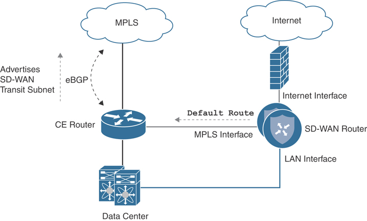
Figure 12-2 Data Center Direct Transport Side
Note
Cisco highly recommends that you ensure that all Cisco SD-WAN routers have connectivity into all transports being leveraged as a part of the overlay in order for high availability and for Application-Aware Routing to work optimally. Typically, this is achieved by providing direct connectivity from each Cisco SD-WAN router into every WAN or Internet Edge router or through the use of Transport Locator (TLOC) extensions.
Note
If NAT is required in order to provide connectivity to the Internet for the Cisco SD-WAN router, it is recommended to configure a static 1:1 NAT whenever possible to avoid tunnel bring-up issues that might occur in some uncommon scenarios.
Indirect connectivity to the Transport Edge is also supported and can be accomplished through the use of VLANs and dedicated interfaces or sub-interfaces. In this example, three VLANs are provisioned: VLAN 10 for the LAN service-side connection, VLAN 20 for the MPLS transport-side connection, and VLAN 30 for the transit between the data center core and the CE router. Routing to the WAN Edge remains the same as in the directly connected design. Figure 12-3 details this type of connectivity.
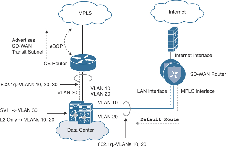
Figure 12-3 Data Center Indirect Transport Side
While this approach is simple and effective, utilizing a routing protocol on a VPN 0 transport interface may be required in some scenarios where direct connectivity to the edge of the WAN is not feasible, or some type of path manipulation or underlay traffic engineering is required. In this scenario, a routing protocol such as BGP or OSPF can be configured in order for the router to learn more specific prefixes, and traditional route policies can be applied inbound and outbound.
Note
When utilizing a routing protocol on VPN 0 to gain access to the underlay, it is important to ensure that the correct and optimal path to peer tunnel endpoints for that particular transport is followed through the local network. This is not a concern when connecting directly to the edge of the WAN since it always guarantees that the next hop will carry the tunnel traffic directly onto the desired transport.
In some advanced topologies, an organization may want to leverage multiple CE routers and circuits to the same service provider for overlay connectivity and may also want to retain granular path selection and control via Cisco SD-WAN policy. Because a single transport color cannot be used twice by the same Cisco SD-WAN router, two alternative TLOC designs exist to meet these requirements.
Loopback TLOC Design
With this design, a loopback interface is configured as a conventional TLOC and is advertised towards both CE routers via two connections (one to each CE). This way, both CEs can reach the Cisco SD-WAN tunnel endpoint configured on the loopback, and the Cisco SD-WAN router can reach the underlay via both CEs. The drawback to this solution is that it requires additional routing complexity. In addition, because there is only a single color configured, path selection granularity via Cisco SD-WAN policy is also limited. It should be noted that two modes exist for this loopback—bind mode and the standard mode. In bind mode, the loopback is bound to a physical interface and traffic destined to the loopback will be carried to and from the mapped physical interface. This can be used when you have connected subnets on the transport side and want to use a loopback to form control connections and data tunnels. Figure 12-4 showcases the bind mode option.
Figure 12-4 Loopback TLOC Bind Mode
In the standard mode, the loopback interface is not bound to any physical interface. Traffic destined to the loopback can go through any physical interface based on a hash lookup. Figure 12-5 illustrates this.
Figure 12-5 Loopback TLOC Standard Mode
Note
It is important to note that in the normal mode, information collected via Bidirectional Forwarding Detection (BFD) can be on any of the interfaces. Because of this, the liveliness info can be seen as different for each remote site, even though the remote sites are on the same local color at this location.
Service-Side Connectivity
Service-side connectivity is commonly achieved by provisioning one or two interfaces in a service VPN and connecting them into the data center core. The data center core is typically a point in the network where aggregation of legacy routes and Cisco SD-WAN routes occurs and allows for natural transitive connectivity. Usually, a routing protocol (such as BGP) is run between the Cisco SD-WAN router and the data center core so that the Cisco SD-WAN router can learn both data center and legacy WAN routes as well as advertise migrated site routes back toward the data center. External BGP (eBGP) is typically the protocol of choice, as it provides built-in loop prevention mechanisms (AS Path and Site of Origin) and has a very flexible and comprehensive path selection algorithm. This algorithm can be manipulated in both directions via route policy. For instance, a route policy could match a set of routes from the overlay and set a local preference in order to influence the data center core. BGP Multi-Exit Discriminator (MED) can also be leveraged for path selection and is actually carried within Overlay Management Protocol (OMP) for vSmart path selection in the overlay. Lastly, BGP also provides granular tagging and filtering mechanisms through the use of route maps, prefix lists, and communities. Figure 12-6 details this type of connectivity.

Figure 12-6 Service-Side BGP
While eBGP is usually the recommended service-side routing protocol, depending on the platform, Cisco SD-WAN supports iBGP, OSPF, EIGRP, Static Routing, and configuration of the first-hop redundancy protocol VRRP as well. Selecting an appropriate service-side routing protocol for an organization depends completely on the existing network configuration, required features and functionality, as well as operator comfort level.
In some instances, using a service-side routing protocol that is different from the existing routing protocol deployed in the data center core can add complexity—especially when it comes to route redistribution between the two protocols. To avoid this complexity, it may be worth considering the same routing protocol on the Cisco SD-WAN router that is found on the data center core. An alternative approach is to connect and peer the service side of the SD-WAN router directly with an existing WAN Edge router (that is, the MPLS CE) already running BGP. This way no additional redistribution needs to occur on the data center core since the WAN Edge router is already providing this functionality. Routes from the Cisco SD-WAN overlay would be learned by the WAN Edge router, and as long as the routing policy permits, they will be redistributed into the protocol running on the data center core. Conversely, the routes learned on the WAN Edge router from the data center core would be redistributed into 468BGP and learned by both the Cisco SD-WAN router and the service provider. The diagram in Figure 12-7 details this type of connectivity.
Figure 12-7 Service-Side CE Integration
Note
As with any other routing integration exercise, it is important to ensure that path selection occurs as desired, loops are avoided, failover performs as expected, and routing is not suboptimal. The aforementioned route manipulation, filtering, and tagging tools supported on Cisco SD-WAN should be leveraged to achieve this.
Keep in mind that while the aforementioned Cisco SD-WAN data center designs are the most recommended and widely deployed, many other methods of providing transport and service-side connectivity do exist and can be investigated for their value, specific to the organization’s needs. For instance, sub-interfaces can be leveraged for both LAN and WAN connectivity if port density is a concern or if the requirement to transit through a switch of transparent firewall is applicable. In the end, we are dealing with traditional routing and switching, and many basic design concepts still hold true.
Finally, once all remote sites have been migrated to Cisco SD-WAN, it is possible (but not mandatory) to decommission the legacy WAN Edge routers terminating the transport circuits. The transport circuits will need to be re-terminated on the Cisco SD-WAN routers directly, which could potentially change the connectivity design and configuration. In short, control plane connectivity will need to be provided to VPN 0 in some manner. While decommissioning the legacy WAN Edge routers might seem like the right thing to do, many organizations opt to keep them in service so as to retain compartmentalization and minimize complexity. Figure 12-8 illustrates this potential post-migration design where the WAN Edge router is removed.

Figure 12-8 Direct Transport Termination
Note
Refer to Cisco’s published migration guides and Cisco Validated Design guides for detailed step-by-step instructions on migration and sample configurations.
Cisco SD-WAN Branch Design
Once the data centers have been migrated to Cisco SD-WAN, the branches can then follow suit. Cisco SD-WAN branch design can be a bit tricky when compared to the data center. Most organizations have branches that come in all shapes and sizes with different topologies, WAN connectivity models, high availability, and additional services (such as voice and security) that need to be taken into consideration. This migration to Cisco SD-WAN could be your opportunity to enforce standardized branch designs and make use of the power of device and feature templates. Because it would not be feasible to detail how to migrate every single branch design, the following portion of this chapter will focus on those designs that are most common.
Complete CE Replacement—Single Cisco SD-WAN Edge
The replacement (or upgrade) of a single WAN Edge to a Cisco SD-WAN Edge requires downtime, as there is no other router to forward traffic during the migration. This design is very straightforward and simply requires you to physically or logically terminate the circuits on the transport side of the Cisco SD-WAN Edge router as well as connect the service side to a LAN core. No routing protocol is required on the transport side, as a default route(s) is used to direct traffic to the respective carrier’s next-hop IP address. Both Layer 2 and Layer 3 service-side connectivity is supported. The Cisco SD-WAN Edge can connect to the LAN via 802.1Q sub-interfaces and act as the Layer 3 gateway for all of the service-side VLANs. Alternatively, depending on the platform, the Cisco SD-WAN Edge can peer with a Layer 3 LAN core via BGP, OSPF, or EIGRP. In the Layer 2 design, the connected subnets are automatically redistributed into OMP and end-to-end reachability is achieved. Figure 12-9 depicts this type of L2 design.

Figure 12-9 Complete CE Replacement—Single Router L2 Branch
In the Layer 3 design, the routing protocol used on the service side must be redistributed into OMP, and OMP must be redistributed into the service-side routing protocol explicitly. Figure 12-10 depicts these designs.
Figure 12-10 Complete CE Replacement—Dual Router L3 Branch
Complete CE Replacement—Dual Cisco SD-WAN Edge
Branches that require high availability might have two WAN Edge routers that need to be replaced. In this scenario, it is possible to provide a near hitless cutover since one router can be replaced or upgraded at a time while the other router continues forwarding traffic. Using routing protocol path manipulation and/or VRRP priority adjustment, it would be necessary to first ensure that all the inbound and outbound traffic is shifted to flow over the router not being initially upgraded. Once one of the routers is replaced or converted to Cisco SD-WAN, traffic can then be shifted over to the newly brought up Cisco SD-WAN overlay network while the other router is also replaced or upgraded.
In this design, depicted in Figure 12-11, both Cisco SD-WAN routers have access to all transports directly—either through multiple handoffs or by utilizing multiple IP addresses and WAN Edge switching infrastructure.
Figure 12-11 Complete CE Replacement—Dual Router L2 Branch
In addition, users have the choice of leveraging a routing protocol or VRRP and static routing for service-side integration, as illustrated in Figure 12-12.

Figure 12-12 Complete CE Replacement—Dual Router L3 Branch
It is a very common scenario where only a single physical handoff and IP address is available on a given transport and yet that transport must be terminated into two Cisco SD-WAN routers. It is highly recommended that both routers have direct or indirect connectivity into all transports being leveraged for the Cisco SD-WAN overlay so that high availability and Application-Aware Routing performs optimally. In this scenario, a public color and private color TLOC extension can be used to meet the requirement. A TLOC extension is a direct or indirect connection between two Cisco SD-WAN routers that extends a locally terminated TLOC to a peer Cisco SD-WAN router. This allows a Cisco SD-WAN router to leverage a non-locally connected transport as a part of the Cisco SD-WAN overlay. TLOC extensions can be bidirectional (if both transports need to be extended) or unidirectional (if only a single transport is to be extended). Figure 12-13 showcases bidirectionally configured TLOC extensions.

Figure 12-13 TLOC Extension Dedicated Interfaces
In some scenarios, it might be necessary to use sub-interfaces to configure TLOC extensions directly between two routers or through a LAN core, as there may not be sufficient physical interfaces free. Figure 12-14 depicts this option.

Figure 12-14 TLOC Extension Sub-Interfaces
In addition, IOS-XE-based Cisco SD-WAN routers support Layer 3 TLOC extension via GRE. This removes the requirement for the routers to have direct Layer 2 adjacency to one another. Hence, they can be geographically separated (as might be the case in a campus environment with multiple data centers).
When extending a private color via TLOC extension, you need to allocate a new enterprise routable transit network for the connection between Cisco SD-WAN routers. On the router extending the locally connected private transport, a dynamic routing protocol should be configured in VPN 0 and peered with the service provider in order to advertise reachability of the new transit network. A route policy can be configured in order to filter inbound and outbound routes so that only the transit network is advertised out and no other networks are learned. Remember, in most cases a default route toward the service provider is all that is needed for tunnel building and control plane connectivity. The Cisco SD-WAN router receiving the extension is not aware of anything different and configures its end of the extension as a standard private TLOC with a default route pointing toward the adjacent next-hop IP on the newly created transit network. Figure 12-15 highlights the private TLOC extension.

Figure 12-15 TLOC Extension Private
Note
Ensure that the Cisco SD-WAN router receiving the extension is able to build control connections through the peer by allowing the transit network to be learned by the data center (where the control components might reside) or allowed through the Internet Edge firewall, where it can egress to reach the cloud controller complex.
Extending a public color via TLOC extension is configured a bit differently than private TLOC extensions. With a public TLOC extension, any locally significant private transit network can be allocated between Cisco SD-WAN routers to build the connectivity. On the router extending the public transport, enable NAT on the egress interface toward the transport so that a unique private-to-public mapping can occur for both of the Cisco SD-WAN routers communicating with other remote sites and the controller complex. Like with a private TLOC extension, the Cisco SD-WAN router receiving the extension is not aware of anything different and configures its end of the extension as a standard public TLOC with a default route pointing toward the adjacent peer’s next-hop IP on the newly created transit network. Figure 12-16 shows an example of a public TLOC extension.
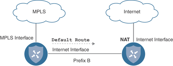
Figure 12-16 Public TLOC Extension
Integration with Existing CE Router
Sometimes a branch design calls for the integration of the Cisco SD-WAN router with an existing CE router. For example, some MPLS carriers provide and manage the CE router and, as a part of the contract, the router cannot be removed from the branch site. In other cases, the existing CE router may be providing other services for the branch that must stay intact post-migration (such as voice gateway functionality). In order for the Cisco SD-WAN router to have connectivity into the MPLS underlay, the design must be made such that the Cisco SD-WAN router can tunnel through the existing MPLS CE. This can easily be accomplished by connecting a physical or logical transport-side interface, configured as a private TLOC in a /30 transit network, to an available interface or sub-interface on the existing CE router. The Cisco SD-WAN router would then be configured with a default route pointing to the next-hop IP address of the MPLS CE. In addition, to provide connectivity to the tunnel endpoint IP address, the MPLS CE router will need to advertise this transit network into the underlay network via a routing protocol such as BGP. The diagram in Figure 12-17 depicts this scenario.

Figure 12-17 Branch CE Integration
Integration with a Branch Firewall
It isn’t uncommon for a branch site to have a firewall terminating Internet connectivity and providing services such as Direct Internet Access (DIA), secure access control, zone-based segmentation, URL filtering, NAT, and IDS/IPS. Because of the routing DNA embedded in Cisco SD-WAN, there are all sorts of methods to integrate with a branch firewall, depending on the desired traffic flow and traffic visibility requirements.
Firewalls can be inserted at the WAN Edge north of the SD-WAN router, in parallel with the Cisco SD-WAN router or even behind the Cisco SD-WAN router in either a Layer 3 routed or Layer 2 transparent mode. Choosing the appropriate integration model depends on several factors, such as physical connectivity, logical traffic flow, traffic visibility requirements, segmentation architecture, NAT requirements, and so on. The only requirement for the Cisco SD-WAN router is that it is provided transport-side Internet connectivity for control and data plane tunnels as well as service-side LAN connectivity to receive and forward user traffic in and out of the overlay.
If all Internet-bound traffic is backhauled to a data center or hub egress point, firewall integration is very straightforward. In this design, the firewall terminates the Internet connection directly and provides access to the WAN Edge through either an allocated public IP address in a DMZ or through NAT (1:1 or PAT).
Note
While Cisco SD-WAN supports tunneling through several types of NAT, symmetric and port-restricted NAT can cause tunnel establishment failures (especially if this type of NAT is on both sides of the tunnel). Refer to the Cisco SD-WAN Validated Design guides for details on supported NAT configurations.
Secure DIA is one of the key benefits of migrating to Cisco SD-WAN, and the following design options are focused on providing this functionality.
In some networks, it is beneficial for the firewall to provide DIA functionality to clients since it may be running advanced security services such as URL filtering. With this design, Internet-bound traffic ingresses the service side of the Cisco SD-WAN router and, instead of performing NAT and local egress itself, the Cisco SD-WAN router forwards the traffic over another service-side link to the adjacent firewall. The firewall can then perform inspection, access control, and NAT prior to forwarding the traffic to the Internet. Traffic to private network destinations follows the Cisco SD-WAN overlay. This is most optimal when the Internet handoff has more than one physical port. Figure 12-18 details this design.
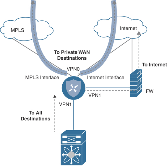
Figure 12-18 DIA Through Firewall
If a dedicated handoff to the Internet is not available, an alternative design would be to connect the transport side of the SD-WAN router to the firewall. In this way, the Cisco SD-WAN router has access to the Internet for control and data plane tunnels while also keeping a separate service-side connection to forward Internet-bound traffic to the firewall for processing and local egress. Figure 12-19 details this design.
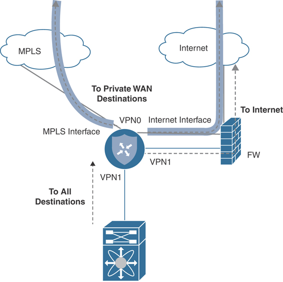
Figure 12-19 Transport and DIA Through Firewall
Lastly, if you wish for all traffic to flow through the Cisco SD-WAN router and only a single connection exists between the router and the firewall, consider the following design. With this design, only a single Cisco SD-WAN transport-side connection is required and is utilized for both tunneling and Direct Internet Access. NAT is configured on the Cisco SD-WAN transport-side interface connected to the firewall, and SD-WAN policy can selectively break out Internet-bound traffic to the underlay. The firewall receives this Internet-bound traffic and may perform a second NAT, as it sends the traffic to the Internet. It is important to note that because the Cisco SD-WAN router is performing NAT (which is a requirement for Cisco SD-WAN routers to break out traffic locally), the firewall loses visibility into the original client source IP addresses. Figure 12-20 showcases this design.
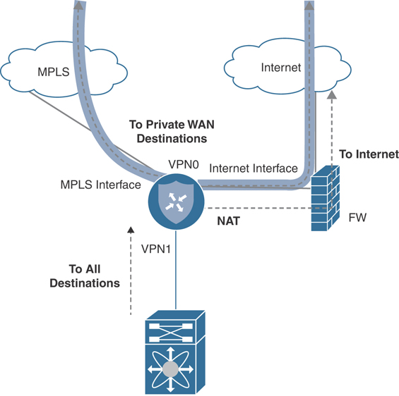
Figure 12-20 Transport and DIA Through Firewall Single Link
Integration with Voice Services
Some branch sites may have voice services, such as SRST, deployed that need to stay functional post-migration. As of version 19.2, there is no voice service integration on routers running Cisco SD-WAN code. Therefore, a dedicated voice gateway must be implemented. A dedicated voice gateway can be an existing CE not running Cisco SD-WAN code but providing SRST and PSTN services. Or it can be a completely separate router configured solely for voice. One such way to integrate a dedicated voice services gateway would be to connect it to the LAN as if it was a host on the network. Either a routing protocol can be configured to advertise the loopback IP address terminating the voice services or VRRP can be implemented to take over voice services should the Cisco SD-WAN overlay incur an outage. Figure 12-21 illustrates the L2 voice service integration design.

Figure 12-21 Voice Services Integration—L2
As mentioned earlier, voice services can also leverage L3 in this design. Figure 12-22 illustrates the L3 voice service integration design.

Figure 12-22 Voice Services Integration—L3
Cisco SD-WAN Overlay and Underlay Integration
This section details how integration between the underlay and overlay networks can be achieved through several design options.
Overlay Only
To minimize complexity and the potential for routing loops, it is recommended to adhere to the aforementioned designs for data center and branch migration. These designs have been proven time and time again to provide a graceful migration solution for organizations of all sizes, complexities, and applications types. Overlay-only-based migrations provide a clear and deterministic traffic flow and are easy to control, scale, and troubleshoot. Figure 12-23 showcases a Cisco SD-WAN site to a non-Cisco SD-WAN site design.
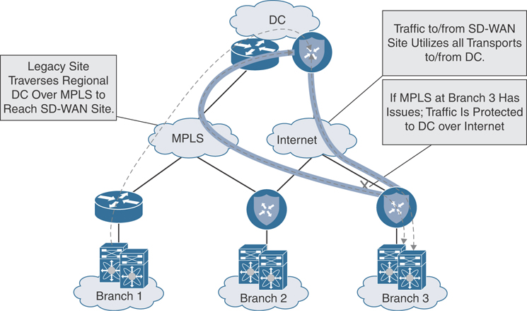
Figure 12-23 SD-WAN to Non-SD-WAN Site Overlay-Only Traffic Flow
Understanding the traffic flow from an SD-WAN site to another SD-WAN site is also critical. Figure 12-24 highlights the traffic flow patterns experienced when employing an overlay-only design.
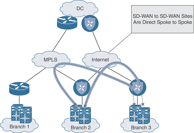
Figure 12-24 SD-WAN to SD-WAN Site Overlay-Only Traffic Flow
Overlay with Underlay Backup
If a branch site leveraging MPLS and Internet for the Cisco SD-WAN overlay has only a single Cisco SD-WAN router employed alongside the MPLS CE, another design opportunity exists that can allow for a backup path to become active if the Cisco SD-WAN router were to fail. For this design to work properly, routing needs to be manipulated in such a way that the site prefixes advertised by the MPLS CE into the underlay are less preferred in the network than those being advertised by the Cisco SD-WAN router into the overlay. Conversely, from the perspective of the LAN, the Cisco SD-WAN router should be the preferred path to reach remote networks. Figure 12-25 illustrates this.

Figure 12-25 Overlay with Underlay Backup—L2 Design
This manipulation of path preference ensures that the traffic flow stays symmetric over the Cisco SD-WAN fabric and only utilizes the underlay if the Cisco SD-WAN router were to fail. One way to manipulate path preference for the underlay is to only advertise local site prefixes from the MPLS CE to the service provider using BGP AS path prepending. Figure 12-26 depicts this type of scenario. Naturally, the data center will advertise the remote site prefixes learned from the data center Cisco SD-WAN router into the underlay with a shorter AS path, ensuring a more preferred, symmetric flow.
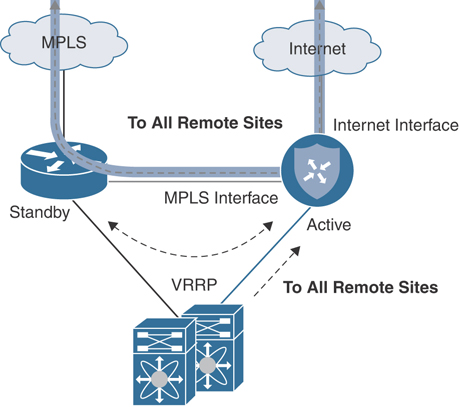
Figure 12-26 Overlay with Underlay Backup—L2 Design Traffic Flow
It should be noted that LAN-side routing also needs to be manipulated in order to prefer the Cisco SD-WAN router (for normal operation) and fail over to the MPLS CE during an impaired state. This can be accomplished in a Layer 2 branch by running VRRP between the Cisco SD-WAN router and the MPLS CE (with the Cisco SD-WAN router having the higher priority). Figure 12-27 depicts this design option.
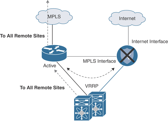
Figure 12-27 Overlay with Underlay Backup—L2 Design Traffic Flow During Failover
In a Layer 3 branch design, advertising remote prefixes to the LAN with a more attractive metric from the Cisco SD-WAN router is also an option. Figure 12-28 illustrates.
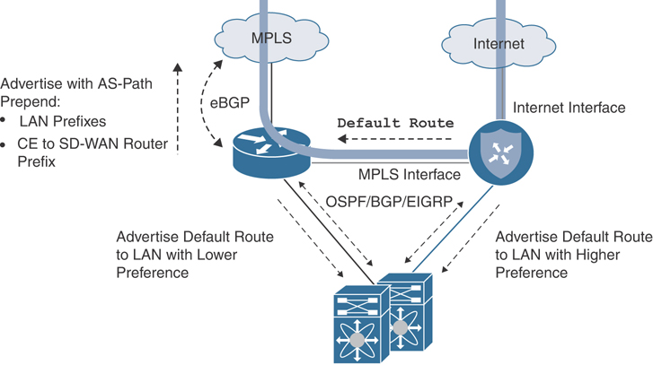
Figure 12-28 Overlay with Underlay Backup—L3 Design
Finally, for the underlay backup architecture to work correctly, it is important to do some filtering at the data center. To ensure that remote branch routes are learned and preferred through the overlay (and asymmetry or route looping is avoided), create a filter outbound toward the Cisco SD-WAN router to limit the learned routes to those originating from the data center. Make sure to also advertise a default or summary into the overlay. Figure 12-29 depicts this design consideration.
Figure 12-29 Overlay with Underlay Backup—Data Center Considerations
Figure 12-30 reviews the traffic flow patterns experienced when employing an overlay with an underlay backup design.
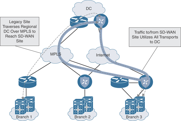
Figure 12-30 Overlay with Underlay Backup Traffic Flow
It is also important to see the traffic flow during a failover condition. This helps visualize the path the traffic will take during a failure scenario. Figure 12-31 highlights the backup traffic flow during a failover event.
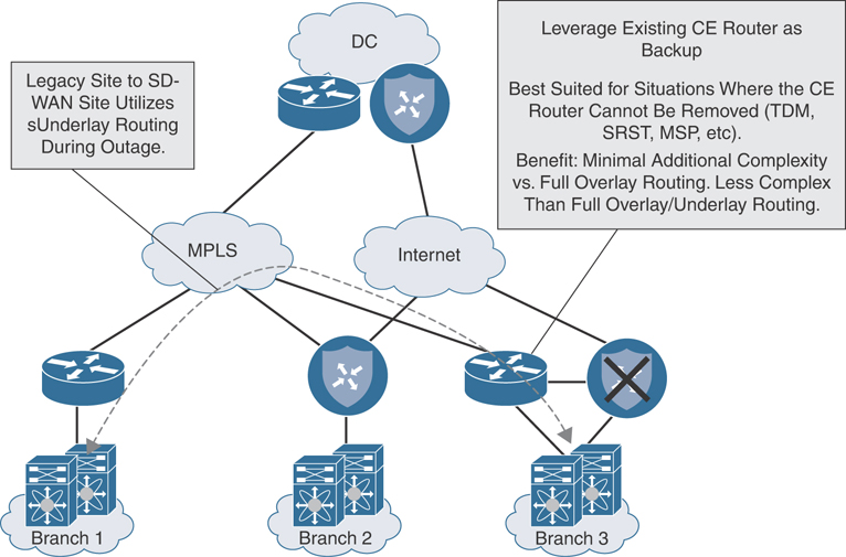
Figure 12-31 Overlay with Underlay Backup Traffic Flow During Failover
Full Overlay and Underlay Integration
For some organizations, due to strict application latency requirements, select branches migrated to Cisco SD-WAN may need to communicate directly to non-migrated branches through a lower latency underlay path. For example, CIFS traffic can be relatively sensitive to latency and may suffer by going through an additional hop at the data center for transit to another site. To meet this latency requirement, it is possible to architect the solution in such a way that the overlay path is used to communicate with migrated sites and the underlay path is used to communicate with non-migrated sites. In contrast to the aforementioned design options, this section showcases the traffic patterns experienced when employing a full overlay and underlay integration design. Figure 12-32 shows routing from a non-Cisco SD-WAN site to a Cisco SD-WAN site.

Figure 12-32 Full Overlay with Underlay Routing Legacy Site to SD-WAN Site Traffic Flow
It is also critical to see the traffic flow of a Cisco SD-WAN site to another Cisco SD-WAN site while leveraging a full overlay and underlay integration design. Figure 12-33 illustrates this concept.

Figure 12-33 Full Overlay with Underlay Routing Cisco SD-WAN Site to Cisco SD-WAN Site Traffic Flow
Note
In most cases, configuring full overlay and underlay integration at every site will add a significant amount of routing complexity to the network and, in some environments, can be a challenge to scale and control. Typically, voice applications can handle 300ms of round-trip latency and therefore this design might not even be required.
One way to implement full overlay and underlay integration at a branch is through the use of an existing MPLS CE router. This design is similar to the MPLS CE integration solution discussed previously, save for the exception that the CE continues to advertise the site prefixes into the MPLS underlay at the same time that the Cisco SD-WAN router advertises the site prefixes into the overlay. Both the MPLS CE router and Cisco SD-WAN router advertise prefixes from the WAN into the LAN. However, Cisco SD-WAN migrated site prefixes (including data center prefixes learned via the MPLS CE) should be advertised with a more attractive metric so as to retain traffic symmetry and to force Cisco SD-WAN sites to talk to each other via the overlay. While any routing protocol can be used to achieve this design, iBGP is recommended for its native anti-transit logic. If any other routing protocol is used, tagging and filtering mechanisms should be employed so as to avoid making the branch into a transit site. Figure 12-34 shows this design option.
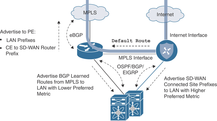
Figure 12-34 Full Overlay with Underlay Routing CE Integration
Figure 12-35 shows the traffic flow for a branch with two transports. Traffic can flow directly through an Internet interface as well as an interface that is connected to an existing MPLS CE router.
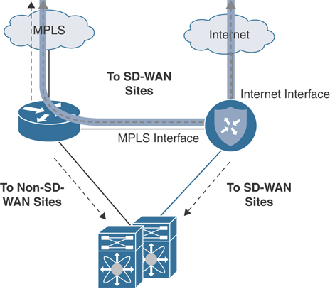
Figure 12-35 Full Overlay with Underlay Routing CE Integration Traffic Flow
Full overlay and underlay integration can also be achieved when no dedicated MPLS CE is present and only a Cisco SD-WAN router exits at the branch. The same principles apply as if there was a separate CE terminating the MPLS connection; however, TLOC termination on the SD-WAN router is a bit different. Instead of configuring the TLOC on the physical interface connected to the MPLS carrier like normal, a loopback interface is created in VPN 0 and configured as the TLOC. The physical WAN interface is bound to the loopback by using the aforementioned “bind” command. A routing protocol is configured between the Cisco SD-WAN router and the carrier in order to advertise the tunnel interface IP address for control and data plane tunnel termination. A VPN 0 interface is then configured and connected to a downstream (LAN-side) Layer 3 switch or looped back into a service VPN interface on the Cisco SD-WAN router. Finally, a routing protocol can be configured on this transit link to learn and advertise routes between the overlay. This configuration, in effect, creates a route leak between VPNs. Figure 12-36 shows this design option.
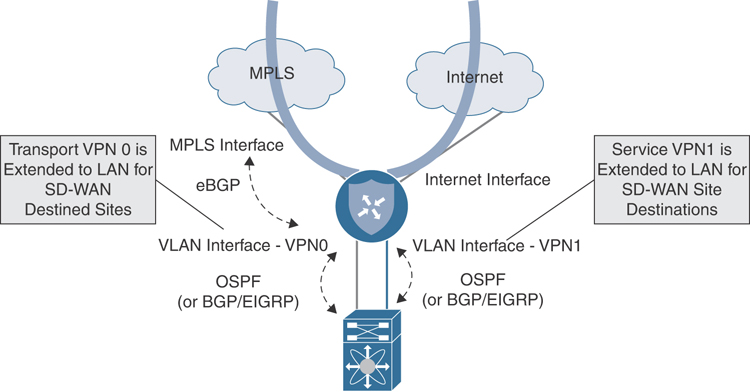
Figure 12-36 Full Overlay with Underlay Routing Without CE Integration
Figure 12-37 illustrates the traffic flow for a site location with no integration with a CE device.

Figure 12-37 Full Overlay with Underlay Routing Without CE Integration Traffic Flow
Note
Additional tagging, filtering, and best path manipulation may be required at both the data center and the remote sites participating in full overlay/underlay connectivity, depending on how routing between the overlay and underlay is accomplished. From a routing perspective, there are many valid ways to achieve full overlay and underlay integration. Each of these options deserves special attention to detail so as not to cause route looping and suboptimal routing. Every environment will come with its own set of complexities and caveats, and it therefore behooves you to think through all of the different possible scenarios specific to your organization’s network that could affect the flow of traffic during and after migration.
Summary
This chapter covered the design methodology recommended for a migration to Cisco SD-WAN. The importance of migration preparation, validated data center and branch designs, as well as overlay and underlay integration techniques was discussed. Migrating to Cisco SD-WAN requires a solid discovery and design period where ample time is spent understanding the existing network thoroughly while also thinking about its future state. Preparation, prior to deploying the Cisco SD-WAN network, is key in ensuring that data center and branch cutovers are executed flawlessly. Understanding the benefits and caveats of all the supported data center and branch designs allows the network architect to select one that meets the requirements of the business and provides additional Cisco SD-WAN functionalities, while maintaining resiliency and performance. All networks have a degree of complexity, and the goal is to migrate to Cisco SD-WAN gracefully without increasing this complexity.
Review All Key Topics
Review the most important topics in the chapter, noted with the Key Topic icon in the outer margin of the page. Table 12-1 lists these key topics and the page numbers on which each is found.
Table 12-1 Key Topics
Key Topic Element |
Description |
Page |
|---|---|---|
Section |
Loopback TLOC Design |
465 |
Paragraph |
TLOC Extension Concept |
473 |
Section |
Cisco SD-WAN Overlay and Underlay Integration |
480 |
Chapter Review Questions
1. Most SD-WAN deployments are done in a greenfield environment.
True
False
2. What are some reasons for a migration to Cisco SD-WAN? (Choose three.)
Application-Aware Routing
Centralized policy
Fast convergence
Scalability
Improved performance
3. Migration to SD-WAN is a hard cut, where all data centers and remote sites are migrated simultaneously.
True
False
4. What are some of the most important preparations that should be made prior to migration? (Choose three.)
Reloading all routers
SD-WAN device template configuration and attachment
Ensuring all routers have a maintenance contract
Analysis of existing topology, routing, and traffic engineering
SD-WAN policy design and configuration
5. What are some classification criteria that can be configured in a list in preparation for policy deployment? (Choose three.)
SNMP OID lists
Prefix-lists
Site-lists
Interface lists
VPN ID lists
6. What type of SD-WAN-specific configuration values should be defined prior to migration? (Choose three.)
Site-IDs
VPN IDs
OSPF hello and dead timers
BGP med values
TLOC colors
7. Standing up SD-WAN routers alongside the current WAN Edge infrastructure is the preferred method for data center SD-WAN router integration.
True
False
8. From a design perspective, how can you improve latency when migrating to SD-WAN while transiting hubs?
Enable TCP optimization
Move the sites closer to each other
Designate multiple regional hubs as transit points
Use dedicated Layer 2 circuits
9. The most common way to integrate transport-side connections on the SD-WAN router into the network is by sharing a single interface in VPN 0 for all carriers/transports.
True
False
10. What is the difference between bind and unbind mode when configuring a loopback TLOC?
Bind mode forms control connections, and unbind mode does not.
Unbind mode takes less router CPU than bind mode.
Unbind mode allows for public and private color connectivity, whereas bind mode does not.
Bind mode ensures traffic destined to the loopback will be carried to and from the mapped physical interface. Unbind mode does not have this behavior.
11. What are three different Cisco SD-WAN branch design options?
Complete CE replacement with a single SD-WAN router
SD-WAN router running inline bridge mode
Integration with existing CE router
Complete CE replacement with dual SD-WAN routers
12. A TLOC extension can only be configured for private colors.
True
False
13. SD-WAN integration with existing firewalls and voice services is not supported.
True
False
14. Which routing protocols are supported for service-side integration with the LAN? (Choose three.)
OMP
OSPF
ISIS
EIGRP
ODR
eBGP
15. What important consideration needs to be made at the data center if implementing overlay and underlay integration designs?
Only OSPF should be used.
ECMP should be configured.
SD-WAN routers should be running the latest code.
Filtering toward the SD-WAN router should be configured.