
Chapter 8. Application-Aware Routing Policies
This chapter covers the following topics:
The Business Imperative for Application-Aware Routing: This section covers the reasons why customers chose to use Application-Aware Routing policies.
The Mechanics of an App-Route Policy: This section covers the necessary steps that must be completed in order to use App-Route policies.
Constructing an App-Route Policy: This section covers the building blocks of an App-Route policy and the process of constructing a simple App-Route policy through the vManage GUI.
Monitoring Tunnel Performance: This section covers the process of using BFD to monitor tunnel performance and how tunnel statistics are calculated.
Mapping Traffic Flows to a Transport Tunnel: This section covers the configuration options inside of an App-Route policy and how those options interact with different transport conditions.
Building on the discussion of centralized data policies in Chapter 7, “Centralized Data Policies,” this chapter focuses on a special type of data policy, the App-Route policy. Application-Aware Routing enables organizations to move away from high-cost, guaranteed performance transport links such as MPLS and move to commodity Internet circuits while not sacrificing application performance. This is accomplished by monitoring the characteristics of the transport links in real time and then incorporating that information into the routing process. This enables network administrators to ensure that their applications are always being forwarded down a path that meets or exceeds the requirements of the application.
The Business Imperative for Application-Aware Routing
One of the key business drivers for many organizations to move to SD-WAN is the ability to replace their existing, expensive legacy transport networks with higher-capacity, less-expensive broadband circuits. This transition is enabled in part by Cisco SD-WAN’s capability to continue to provide an assured application experience over transports without an underlying SLA commitment.
By moving away from existing legacy transport networks and moving to using the Internet as a transport, many organizations are finding that they can dramatically increase their available bandwidth while at the same time reducing their transport costs. However, there is no guaranteed service level, or service level agreements (SLAs), on the Internet. Many organizations have relied upon their leased-line and MPLS transport providers for an assured level of service. While no solution can guarantee an assured level of service over the Internet, Cisco SD-WAN can leverage the benefits of low-cost Internet transports while at the same time utilizing Application-Aware Routing and packet-loss mitigation technologies to bring leased-line benefits to organizations.
Using Application-Aware Routing, network administrators are able to identify business-critical traffic and specify the required service level agreement for that traffic class.
When replacing or augmenting existing MPLS transport circuits with Internet-as-a-Transport, organizations are able to establish multiple connectivity paths between their locations. The ability to move to the Internet as a transport, while still being able to provide for the required end-user experience, enables enterprises to realize cost savings by utilizing all of their bandwidth in an Active/Active fashion, rather than needing to continue to invest in upgrading circuits.
The Mechanics of an App-Route Policy
There are three key parts to the Application-Aware Routing process:
Constructing an App-Route policy: The first step in Application-Aware Routing is to build an App-Route policy. An App-Route policy is a specific type of centralized data policy that has many similarities with the data policies explored in Chapter 7. Constructing the policy includes defining the necessary lists, building the policy from a sequence of match and action statements, and activating the policy.
Measuring and monitoring the performance of the transport links: Once the App-Route policy has been created and activated, the next step in the process is to monitor the performance of the SD-WAN tunnels (in real time) to determine which tunnels are in compliance with the required SLA. This performance information is gathered from Bidirectional Forwarding Detection (BFD) packets, which are sent automatically across each of the different tunnels created as part of the SD-WAN fabric.
Mapping application traffic to a specific transport link: After the tunnel performance has been determined by BFD packets, these metrics are then evaluated against the configured SLA classes to determine which tunnels are in compliance. Forwarding decisions are then made with respect to these SLA compliance states.
The sections that follow explain each of the steps in more detail.
Constructing an App-Route Policy
The first step in building an App-Route policy, just as with the control policies and data policies from Chapters 6 and 7, is to define all of the lists. As we saw with data policies in Chapter 7, a number of criteria can be used to identify traffic of interest. These include traditional Layer 3 and Layer 4 headers, such as IP addresses, protocols, port numbers, and DSCP markings. Administrators can also match traffic based on the Layer 7 application definitions defined as an application-list. Lists are configured from the Lists menu under the Custom Options menu, as shown in Figure 8-1.
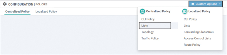
Figure 8-1 Creating Lists for Use in Policies
There is a new type of list used specifically for App-Route policies, called an SLA Class list. Network administrators use an SLA Class list to define the maximum permitted latency, loss, and jitter (or a combination of the three values) that an application class can tolerate while still maintaining the desired end-user experience. If any one of the Loss, Latency, or Jitter values were to exceed the configured threshold in the SLA Class list, the transport would be deemed noncompliant and the application flow would be moved to a different, compliant transport tunnel. In order to be in a compliant state, all three values must be below the configured thresholds. As some types of traffic, such as real-time voice and video, have much stricter network requirements than other types of traffic, it is common for network administrators to configure multiple SLA Class lists. Figure 8-2 shows an example of an SLA Class list that has been configured for Unified Communications traffic called REALTIME_SLA with a maximum packet loss of 2%, a maximum latency of 100ms, and a maximum jitter of 30ms. The CLI configuration for this and subsequent configuration steps is reviewed later in Example 8-1.

Figure 8-2 Creating a New SLA Class List
Once the lists have been defined, the next step in building an App-Route policy is to construct the policy from a sequence of match and action statements. As App-Route policies are a type of data policy, the configuration page for App-Route policies is found in the “Traffic Policy” submenu under Centralized Policy, as shown in Figure 8-3.
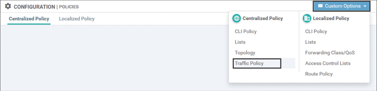
Figure 8-3 Opening the Traffic Policy Configuration Menu
Once you’re on the Traffic Policy configuration tab where the Application-Aware Routing subtab is selected by default, a new App-Route policy can be created by clicking the Add Policy button and selecting Create New, as shown in Figure 8-4.
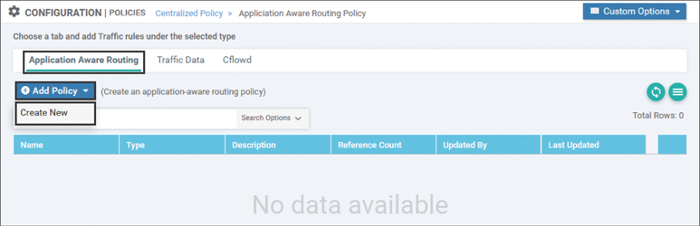
Figure 8-4 Creating a New Application-Aware Routing Policy
The process of building an App-Route policy is identical to the data policies that were built in Chapter 7. The only notable difference is that different actions are used in an App-Route policy. Figure 8-5 shows a simple App-Route policy with a single sequence that matches on traffic marked with DSCP 46 (Expedited Forwarding).
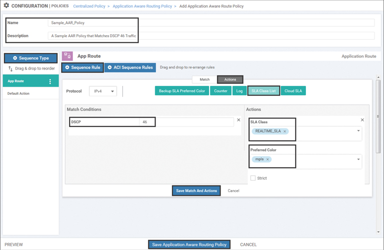
Figure 8-5 Sample Application-Aware Routing Policy
As shown in Figure 8-5, all App-Route policies need to be configured with a name and a description. App-Route policies use the same structures of Sequence Type and Sequence Rule that were seen in centralized control and centralized data policies. In the sample policy displayed in Figure 8-5, the matching criterion of a DSCP value of 46 is specified. The primary action taken in an App-Route policy sequence is called SLA Class List in vManage. Two fields have been configured in this action: SLA Class and the Preferred Color. The SLA Class field references an SLA Class list that was previously configured, specifying the maximum permitted loss, latency, and jitter. The Preferred Color field contains the color or colors that the network administrator desires to forward this application class across, as long as those colors are in compliance with the SLA class. In this example, the network is configured such that DSCP 46 traffic should be forwarded through the tunnel with the color value of mpls, as long as that tunnel is in compliance with the REALTIME_SLA class. A further discussion of logic can be found in the following section, “Mapping Traffic Flows to a Transport Tunnel.” Once the configuration is completed, the sequence rule is saved by clicking the Save Match and Actions button, and the policy is saved by clicking the Save Application-Aware Routing Policy button.
Finally, all App-Route policies need to be applied through a centralized policy. A new centralized policy can be created by selecting the Add Policy button on the Centralized Policy page, as shown in Figure 8-6. The App-Route policy could also be imported into an existing policy by copying and then editing the policy as described in Chapters 6 and 7. That process will not be reviewed in this chapter.
Figure 8-6 Creating a New Policy with the Centralized Policy Wizard
As no additional lists or control policies need to be created for this example, click the Next button twice to skip the Create Groups of Interest and Configure Topology and VPN Membership tabs and move to the Configure Traffic Rules tab, as shown in Figure 8-7.
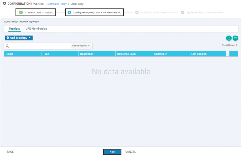
Figure 8-7 Advancing the Centralized Policy Wizard Through Lists and Control Policies
On the Configure Traffic Rules tab, under the Application-Aware Routing subtab, click on the Add Policy button and select the Import Existing option, as shown in Figure 8-8.

Figure 8-8 Importing an Application-Aware Routing Policy into a Centralized Policy
Select the App-Route policy that was created previously and click Import in the window. Click the Next button at the bottom of the page to proceed. Figure 8-9 shows these steps.

Figure 8-9 Selecting the App-Route Policy to Import
The final step in the creation of the centralized policy is to apply the component policies. First, a name and description must be provided for this policy, as shown in Figure 8-10. In order to apply the App-Route policy, select the Application-Aware Routing tab and click the blue New Site List and VPN List button under the Sample_AAR_Policy policy. This particular policy is applied to all of the DCs and all of the branch offices by referencing the site lists created in the previous chapters. Next, specify the VPN or VPNs that the policy is to be applied to. In the case of Figure 8-10, this is the CorporateVPN, VPN 10. Finally, click Add to save the policy application for this policy and then click Save Policy, as shown in Figure 8-10, to complete the centralized policy configuration.
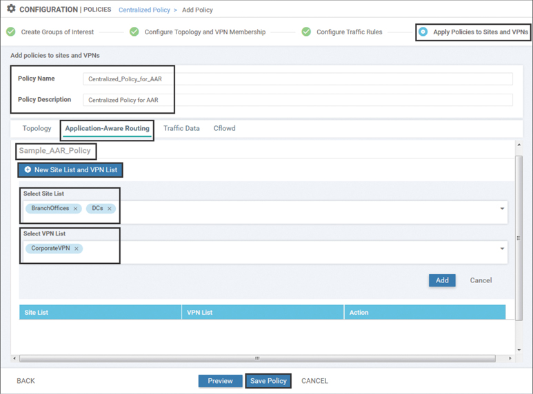
Figure 8-10 Applying an Application-Aware Routing Policy in a Centralized Policy
Note
As an App-Route policy is a type of centralized data policy, it is applied on the vSmart controllers, encoded into an Overlay Management Protocol (OMP) update, and advertised down to the WAN Edge routers where the policies are enforced. Chapter 5, “Introduction to Cisco SD-WAN Policies,” provides additional details on this process.
Chapter 7 discussed that data policies can be applied in a specific direction—either “from-service” or “from-tunnel.” App-Route policies do not have a direction specified when they are applied. App-Route policies are always applied to traffic “from-service” destined to the fabric, as an App-Route policy determines which site-to-site tunnel traffic is forwarded across when it is sent out across the WAN.
Example 8-1 provides the annotated configuration of the entire sample App-Route policy. Just as with the policy examples in Chapter 6, “Centralized Control Policies,” and Chapter 7, “Centralized Data Policies,” the full CLI for a policy created from vManage is available by selecting Preview in the Centralized Policy page. For the remainder of this chapter, AAR policy examples will be presented as configuration snippets for brevity and for illustration. As with all Cisco SD-WAN policies, the configuration can be performed either via the vManage GUI or from the command line.
Example 8-1 Sample App-Route Policy
policy
! The SLA Class that specifies the required tunnel performance
  sla-class REALTIME_SLA
   latency 100
   loss 2
   jitter 30
  !
! The AAR policy that is composed of 'match' and 'action' sequences
app-route-policy _CorporateVPN_Sample_AAR_Policy
 vpn-list CorporateVPN
   sequence 1
     match
      dscp 46
      source-ip 0.0.0.0/0
     !
! The sla-class action specifies the SLA Class and the preferred colors
     action
      sla-class REALTIME_SLA  preferred-color mpls
     !
    !
 !
! Additional lists used within the policy. In this case, these lists are used
! when the policy is applied.
 lists
  site-list BranchOffices
   site-id 100-199
  !
  site-list DCs
   site-id 10-50
  !
  vpn-list CorporateVPN
   vpn 1
  !
 !
!
! The AAR policy is applied to selected Site Lists and VPN Lists.
! Note: There is no directionality to this policy.
apply-policy
 site-list DCs
 app-route-policy _CorporateVPN_Sample_AAR_Policy
 !
 site-list BranchOffices
 app-route-policy _CorporateVPN_Sample_AAR_Policy
 !
!
Monitoring Tunnel Performance
The Bidirectional Forwarding Detection (BFD) protocol is used to monitor the real-time condition of the underlying transport network. BFD packets are initiated by each router across every tunnel that is brought up as part of the SD-WAN fabric and serve two different purposes: liveliness detection and path quality monitoring. BFD packets are echoed bidirectionally across each tunnel and, as such, active BFD neighbors are not formed across the SD-WAN fabric. Figure 8-11 illustrates this process.
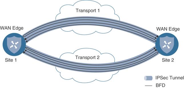
Figure 8-11 BFD Packets in the SD-WAN Fabric
As shown in Figure 8-11, each router initiates a BFD packet on each tunnel. When the packet is received by the router at the far end of the tunnel, it is echoed back to the originating router. The configuration parameters for BFD probes are set in the BFD feature template and are referenced in the individual device templates. In this way, different routers can have different BFD settings.
Liveliness Detection
There are several configurable options inside the BFD template, as seen in Figure 8-12.

Figure 8-12 BFD Feature Template
The two sections to the BFD template are the Basic Configuration section and the Color section. The Basic Configuration section has the configuration elements related to Application-Aware Routing and will be discussed later. The Color section contains two foundational settings: per-color Hello Interval and Multiplier. As shown in Figure 8-12, these two settings allow you to have different values for different colors, providing network administrators the ability to configure different settings for different transport links. A common design choice is to have more aggressive BFD timers on wired connections and more conservative timers on cellular connections where customers are often charged per gigabyte.
Hello Interval
The Hello Interval specifies how frequently a BFD probe will be sent across a given tunnel. The default value for this timer is once per second, and the value is specified in milliseconds. In Figure 8-12, the Hello Interval for the MPLS and Biz-Internet colors is set to 200 milliseconds. The Hello Interval for the LTE color is set to 1000 milliseconds (ms).
However, when different devices have different BFD timers configured for the same tunnel, BFD will negotiate to use the greater of the two values. Figure 8-13 illustrates one example where this negotiation behavior is beneficial. Many times, WAN Edge routers are using different colors at each end of an SD-WAN tunnel. This commonly occurs when transports such as LTE are used to connect to the Biz-Internet TLOCs at other branches or the Biz-Internet TLOCs at the data center, where the LTE TLOC may not be configured at all. In these circumstances, having the tunnels that utilize the LTE TLOCs (at either end of the tunnel) use the slower timers would help to conserve LTE bandwidth, while at the same time ensuring that the tunnels that are running completely on the wireline TLOCs continue to use the more aggressive timers.
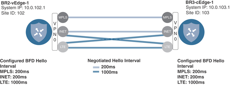
Figure 8-13 BFD Hello Interval Negotiation
Figure 8-13 illustrates a scenario where the WAN Edges will negotiate to use the greater of the two configured BFD Hello Intervals for an SD-WAN tunnel. After the configuration shown in the BFD feature template in Figure 8-12 is applied, this effect can be seen by using the Real Time output of BR2-vEdge-1, as shown in Figure 8-14.
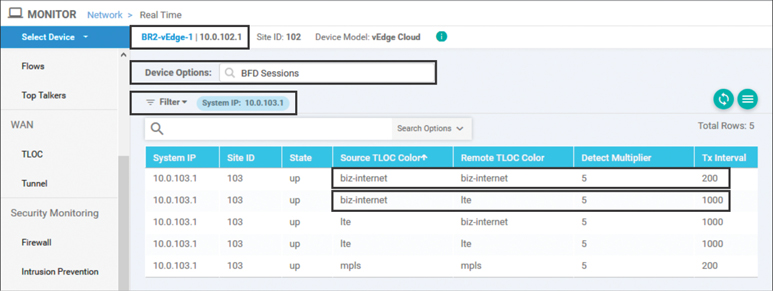
Figure 8-14 Effects of BFD Hello Interval Negotiation
Figure 8-14 shows that the BFD sessions between these two WAN Edges are being negotiated to the greater of the two configured values. In the first row in the table, the tunnel that originates on the Biz-Internet TLOC (configured with a Hello Interval of 200ms), destined to the remote router’s Biz-Internet TLOC, is operating with a Tx interval (the negotiated Hello Interval) of 200ms. In the second row in the table, the tunnel that originates from the same TLOC but is destined for the LTE TLOC at the far end of the tunnel has a Tx interval of 1000ms.
Multiplier
The Multiplier value specifies how many consecutive BFD probes can be lost before declaring the tunnel to be down. This feature forms the basis of liveliness detection and is useful for detecting things such as indirect fiber cuts, where the physical interface remains in an “Up” state but no traffic can be sent across a link. In circumstances where the transport interface state changes from Up to Down, there is no need to wait for the multiplier to expire, as the tunnel is immediately set to Down and the corresponding routes are withdrawn. The default Multiplier value is 7, and in Figure 8-12, the value has been changed to 5.
Figure 8-15 illustrates the relationships between the Hello Interval, the Hello Multiplier, and the amount of time it takes to detect a circuit failure for the values configured for the MPLS Color in Figure 8-12.

Figure 8-15 BFD Path Liveliness Detection
As Figure 8-15 illustrates, with a configured Hello Interval of 200 milliseconds and a configured Hello Multiplier of 5, it would take approximately 1,000 milliseconds to detect an indirect circuit failure. With the default Hello Interval of 1 second (1,000 msec) and the default Multiplier of 7, it is possible it would take the SD-WAN solution 7 seconds (1 packet per second × 7 packets) to detect an indirect circuit failure. Further information and recommendations for setting these timers can be found later in this section.
Path Quality Monitoring
In addition to liveliness detection, these same BFD packets are also used to monitor the performance and quality of each of the transport paths. These settings are shown in the Basic Configuration section of Figure 8-12 and include the App-Route Multiplier and the App-Route Poll Interval. As indicated by Figure 8-12, the Poll Interval and the Multiplier are per-device settings; there is only one App-Route polling interval and only one App-Route multiplier setting for each WAN Edge router.
App-Route Poll Interval
The App-Route Poll Interval is defined as a period of time for which the WAN Edge router will calculate the loss, latency, and jitter for each tunnel using the BFD packets sent during that interval. App-Route Poll Intervals are occasionally referred to as “buckets” as they represent the statistics from a collection of individual BFD packets. The WAN Edge routers will then proceed to calculate or recalculate each tunnel’s SLA compliance and proceed to forward packets in accordance with the configured App-Route policies until the end of the next App-Route Poll Interval, when the cycle repeats.
Figure 8-16 illustrates a sample poll interval with a duration of 10 seconds where BFD packets were sent every 1 second.

Figure 8-16 App-Route Poll Interval Illustration
As illustrated in Figure 8-16, the App-Route Poll Interval is the period of time for which statistics are calculated from the BFD packets sent during that window. The number of BFD packets and, thus, the sample size for that statistical calculation are not explicitly configured but instead are derived from the combination of the length of the Hello Interval and the length of the App-Route Poll Interval.
Expanding the example illustrated in Figure 8-16 further, we can use the data in Table 8-1 to calculate the loss, latency, and jitter during the App-Route Poll Interval.
Table 8-1 Individual BFD Packets During an App-Route Poll Interval
BFD Packet |
Received/Lost |
Round-trip Time |
|---|---|---|
1 |
Received |
10ms |
2 |
Received |
11ms |
3 |
Received |
13ms |
4 |
Received |
11ms |
5 |
Received |
10ms |
6 |
Received |
11ms |
7 |
Received |
10ms |
8 |
Lost |
N/A |
9 |
Received |
12ms |
10 |
Received |
11ms |
At the end of each App-Route Poll Interval, the App-Route statistics are calculated from the BFD packets sent during that interval. Using the data in Table 8-2, the packet loss percentage is calculated from the percentage of BFD packets successfully echoed back to the originating router. The latency is calculated to be 11 milliseconds by the arithmetic mean of the round-trip time for all of the samples where a reply was received ((10+11+13+11+10+11+10+12+11)/9). The jitter is calculated to be 1 millisecond by taking the mean of the absolute value of the difference in the round-trip time ((1+2+2+1+1+1+2+1)/8).
Table 8-2 BFD Statistics Calculated after an App-Route Poll Interval
App-Route Poll Interval |
Loss Percentage |
Latency |
Jitter |
|---|---|---|---|
0 |
10% |
11 msec |
1 msec |
Figure 8-16 and Table 8-2 illustrate a key concept about App-Route Poll Interval and BFD Hello Intervals: It is important to ensure that there are enough BFD probes in a particular poll interval in order to generate statistically significant results. In this particular example, there might have been only .05% packet loss, but because a single BFD probe was lost, and that probe represented 10% of all of the probes, the packet loss is recorded as 10%.
When the values in Table 8-2 are compared against the REALTIME_SLA Class list that was configured in Figure 8-2 and Example 8-1, it is clear that the current loss percentage, 10%, exceeds the configured threshold of 2%. As such, the determination would be made at the end of the App-Route Poll Interval that this path would be out of compliance with the REALTIME_SLA Class list at this point in time. This is shown in Figure 8-17 at Time “A” in the next section.
App-Route Multiplier
The App-Route Multiplier specifies how many polling intervals of previously collected BFD probes to consider when calculating tunnel SLA compliance. This can be thought of as how many different “buckets” are evaluated when looking at circuit performance. The maximum configuration value and the default value of the App-Route Multiplier are 6. The configuration shown in Figure 8-10 uses an App-Route Multiplier of 3. In other words, the statistics from a maximum of three different “buckets” will be considered when calculating tunnel performance. Continuing on with the previous example, Table 8-3 illustrates the App-Route Statistics after the completion of a second App-Route Poll Interval.
Table 8-3 BFD Statistics from Multiple App-Route Poll Interval
App-Route Poll Interval |
Loss Percentage |
Latency |
Jitter |
|---|---|---|---|
0 |
0% |
10 msec |
1 msec |
1 |
10% |
11 msec |
1 msec |
The original statistics from the first App-Route Poll Interval, Interval 0, are moved down the table to the second row (Interval 1). The new values for tunnel performance are calculated by averaging the values from each of the App-Route Poll Intervals in Table 8-3:
Packet Loss = 5%
Latency = 10 msec
Jitter = 1 msec
Figure 8-17 illustrates these App-Route Poll Intervals and the subsequent calculations to determine compliance with the SLA class that occurs at the end of each App-Route Poll Interval. As discussed previously, at time “A,” the circuit would be out of compliance with the SLA class because it experienced 10% packet loss. As there was only a single App-Route Poll Interval that had elapsed, the statistics gathered during this interval are the only statistics available.

Figure 8-17 SLA Calculations with Two App-Route Poll Intervals
At time “B,” two different App-Route Poll Intervals have elapsed. While there was no packet loss in the second interval, the 10% loss from the first interval causes the average packet loss to be 5% and, thus, the circuit still exceeds the SLA class requirement of 2%.
After two more App-Route Poll Interval periods have elapsed, the data in Table 8-4 has been gathered to calculate the SLA statistics.
Table 8-4 BFD Statistics from Four App-Route Poll Intervals
App-Route Poll Interval |
Loss Percentage |
Latency |
Jitter |
|---|---|---|---|
0 |
0% |
200 msec |
25 msec |
1 |
0% |
11 msec |
0 msec |
2 |
0% |
10 msec |
1 msec |
~ |
10% |
11 msec |
1 msec |
First, note in Figure 8-17 that the original statistics from the first example gathered in Table 8-2 are now grayed out. As the configured App-Route Multiplier value is 3, only statistics from the three most recent buckets will be considered for the tunnel performance calculation, and these initial values would have aged out of the table and are no longer considered. From the remaining three values, the following averages are calculated:
Packet Loss = 0%
Latency = 73 msec
Jitter = 8 msec
Building on Figure 8-17, Figure 8-18 illustrates what happens after the conclusion of the next two App-Route Poll Intervals, at times “C” and “D.”
At time “C,” three intervals have elapsed. Even though there has been no additional packet loss, the average packet loss across all three App-Route Poll intervals is 3% and remains out of compliance.

Figure 8-18 SLA Calculations with Multiple App-Route Poll Intervals
At time “D,” the first App-Route Poll Interval is no longer taken into account, as the App-Route Multiplier is configured as 3. As such, the first interval where the packet loss was experienced is not included in the average, and the packet loss average is now calculated as 0%.
If the App-Route Multiplier had been configured to 1 instead of the current value of 3, then only the statistics from Poll Interval #2 would have been taken into account at time “B,” and the transport would have been compliant with the SLA class because the packet loss during Poll Interval #2 was 0%. The same is true at time “C”: If the only Poll Interval considered was #3, then the transport would have been considered compliant. In this way, the App-Route Multiplier functions as a hold-down timer and prevents excessive flapping of application flows between SD-WAN paths that would otherwise be caused by transient events in the underlying transport network. Greater App-Route Multipliers allow for more poll intervals and, therefore, longer periods of time to be considered when calculating compliance with SLA classes. At the same time, the opposite effect can also happen: The latency in Poll Interval #4 has now spiked to 200 milliseconds. While this value is above the stated threshold of 100 milliseconds in the SLA class, the value is averaged with the values from the two previous App-Route Poll Intervals. The average value of these three intervals (73 milliseconds) is below the 100 millisecond threshold; therefore, this circuit will be treated as compliant for the time being. Network administrators can configure both the length of the App-Route Poll Interval as well as the App-Route Multiplier to tune the amount of historical performance to consider when evaluating SLA compliance.
SLA compliance is only reevaluated at the end of the App-Route Poll Interval. Other than moving a tunnel to the Down state because of an interface state change or a failure to receive a Hello packet within the Hello Multiplier, changes to the condition of a circuit will only be evaluated at the end of the App-Route Poll Interval. Hello Intervals, App-Route Poll Intervals, and App-Route Multipliers need to be configured to ensure that the network is responsive enough to changes in network conditions, while also having enough BFD data to gather statistically meaningful metrics. While faster BFD hellos and more aggressive timers may make the network react faster to brownouts, they can increase the susceptibility to false positives. This results in traffic moving from tunnel to tunnel unnecessarily and, thus, a potentially higher administrative burden for the team operating the network.
Note
While the specific design objectives and topologies for an SD-WAN deployment will be unique to each individual enterprise, the following settings are a reasonable starting place for many organizations:
App-Route Polling Interval: 120,000 ms (two minutes)
Hello Interval: 1000 ms (one second)
Hello Multiplier: 7
When these values are considered together, this means that the WAN Edge routers will be able to detect and respond to indirect transport interruptions after 7 seconds (1000ms per BFD hello interval × 7 packets). Individual tunnels will be evaluated for compliance with the SLA classes once every 2 minutes and that compliance will be based on the last 12 minutes of data (2 minutes per polling interval × 6 intervals). Each polling interval will have data from 120 BFD packets (120,000 msec polling interval / 1,000 msec Hello Interval). The higher the number of BFD packets in each polling interval, the better the loss, latency, and jitter statistics will be at truly representing the performance of the underlying transport.
Cisco Validated Design Guides are available at http://cisco.com/go/cvd and can provide additional guidance about tuning these timers for specific network designs.
Mapping Traffic Flows to a Transport Tunnel
After calculating the packet loss, latency, and jitter on a per-tunnel basis, the final step in the Application-Aware Routing process is to map a network data flow to a specific transport tunnel. The process of determining which tunnel should forward a specific flow is first determined by performing the necessary lookup in the traditional routing table. If and only if there are multiple equal-cost matches in the routing table, the App-Route Policy is evaluated to make a forwarding decision.
Packet Forwarding with Application-Aware Routing Policies
This section will continue to use the sample network that has been used throughout Chapters 6 and 7. Specifically, in this chapter, we will be looking at flows that are originating in Branch 2 (10.1.102.0/30) and are destined to Branch 3 (10.1.103.0/24). As such, the validation work and show commands that will be undertaken will occur on BR2-vEdge1. Figure 8-19 shows the relevant excerpt of this topology.

Figure 8-19 Application-Aware Routing Network Topology
Traditional Lookup in the Routing Table
Using the topology in Figure 8-19, we can now consider how App-Route policies affect how flows are mapped to transport tunnels. The first step in the process is to perform a normal routing lookup in the routing table.
The routing table is always considered prior to the evaluation of any App-Route policies. If there is more than one equal-cost route for the destination in the routing table, the App-Route policy will be evaluated in order to potentially select one or more paths from the paths in the table. If there is only one OMP best path installed in the table, and there are vsmartnot multiple, equal-cost routes, then the traffic will be forwarded according to the only route in the routing table and the App-Route policy will not be considered. Application-Aware Routing policies are only used to choose between multiple, equal best paths in the routing table.
As seen in Example 8-2, the WAN Edge router has three different paths to the 10.1.103.0/24 segment at Branch 3 installed in the routing table. Note that each of the routes has the status flags of “F,S” set, indicating that these routes have been selected and installed into the Forwarding Information Base (FIB). Additionally, this output displays the tloc-color for each of the routes. This indicates that we have one route across the MPLS connection, one across the Biz-Internet connection, and one across the LTE connection, as depicted in Figure 8-19.
Example 8-2 Equal-Cost Paths Installed in the Routing Table
BR2-vEdge-1# show ip routes vpn 1 10.1.103.0/24 detail

<<<Omitted>>>

Codes Status flags:
  F -> fib, S -> selected, I -> inactive,
  B -> blackhole, R -> recursive

""--------------------------------------------
 VPN 1      PREFIX 10.1.103.0/24
--------------------------------------------
 proto           omp
 distance        250
 metric          0
 uptime          0:00:36:13
 tloc-ip         10.0.103.1
 tloc-color      mpls
 tloc-encap      ipsec
 nexthop-label   1001
 status          F,S
--------------------------------------------
 VPN 1      PREFIX 10.1.103.0/24
--------------------------------------------
 proto           omp
 distance        250
 metric          0
 uptime          0:00:36:13
 tloc-ip         10.0.103.1
 tloc-color      biz-internet
 tloc-encap      ipsec
 nexthop-label   1001
 status          F,S
--------------------------------------------
 VPN 1      PREFIX 10.1.103.0/24
--------------------------------------------
 proto           omp
 distance        250
 metric          0
 uptime          0:00:36:13
 tloc-ip         10.0.103.1
 tloc-color      lte
 tloc-encap      ipsec
 nexthop-label   1001
 status          F,S

BR2-vEdge-1#
SLA Class Action
If a prefix has multiple equal-cost matches in the routing table and an Application-Aware Routing policy has been created that matches the specific traffic class, then the SLA Class action is evaluated. In this example, we are using an extended version of the policy that was reviewed in Example 8-1. The full policy can be displayed on the vSmart controller using the show running-config policy command, as shown in Example 8-3.
Example 8-3 Expanded Application-Aware Routing Policy
vSmart-1# show running-config policy
policy
 sla-class BULK_DATA_SLA
  loss    10
  latency 300
!
 sla-class CRITICAL_DATA_SLA
  loss    5
  latency 150
 !
 sla-class REALTIME_SLA
  loss    2
  latency 100
  jitter  30
 !
 app-route-policy _CorporateVPN_Expande_-170838785
  vpn-list CorporateVPN
   sequence 1
    match
     source-ip 0.0.0.0/0
     dscp      46
    !
    action
     sla-class REALTIME_SLA preferred-color mpls
     backup-sla-preferred-color mpls
    !
   !
   sequence 11
    match
     source-ip 0.0.0.0/0
     app-list  REALTIME_DATA_TRANSFER
    !
    action
     sla-class CRITICAL_DATA_SLA strict preferred-color mpls
    !
   !
   sequence 21
    match
     source-ip 0.0.0.0/0
     app-list  CRITICAL_DATA
    !
    action
     sla-class CRITICAL_DATA_SLA preferred-color mpls biz-internet
    !
   !
   sequence 31
    match
     source-ip 0.0.0.0/0
     dscp      8
!
    action
     sla-class BULK_DATA_SLA preferred-color biz-internet
    !
   !
  !
 !
 lists
  vpn-list CorporateVPN
   vpn 1
  !
  app-list CRITICAL_DATA
   app-family audio_video
   app-family erp
   app-family microsoft-office
   app-family microsoft_office
   app-family network-management
   app-family network_management
   app-family terminal
   app-family thin-client
   app-family thin_client
   app-family web
  !
  app-list REALTIME_DATA_TRANSFER
   app tftp
  !
  site-list BranchOffices
   site-id 100-199
  !
  site-list DCs
   site-id 10-50
  !
 !
!
vSmart-1#
There have been two new SLA Class lists added to the configuration of this policy: the CRITICAL_DATA_SLA and BULK_DATA_SLA Class lists. Notice that these new SLA classes do not have jitter values configured. In these cases, jitter will not be evaluated as part of the SLA Class criteria.
Reevaluating every tunnel on the WAN Edge router after every poll interval is a CPU- and memory-intensive task. As such, each WAN Edge router is limited to a total of four different SLA Class lists as of software version 19.2. A vSmart policy can contain up to eight different SLA Class lists, but only four of them may be used by the App-Route policies that are configured for a specific WAN Edge. This flexibility is often used by network administrators to configure one set of SLA Classes for their domestic sites and a different set of SLA Classes for their overseas locations.
There have also been several additional sequences added to this App-Route policy. Each one of these sequences is a structured sequence of match and action statements. These sequences are configured with the sla-class action. Each sla-class action references one of the configured sla-class lists (in this example, REALTIME_SLA, CRITICAL_DATA_SLA, or BULK_DATA_SLA), and it lists the preferred TLOC color or colors. The tunnels matching the preferred color or colors, as specified in the SLA Class action, are evaluated against the requirements of the SLA class. If one or more of the preferred colors are in compliance with the SLA class, then that is the color or colors that will be used to forward traffic.
In sequence 1 of the aforementioned policies, the traffic marked with a DSCP value of 46 is configured with the action sla-class REALTIME_SLA preferred-color mpls. This configuration should be interpreted to mean that the traffic class, DSCP 46, needs a transport that meets the requirements of the REALTIME_SLA list. If a tunnel with the color of mpls can meet that requirement, it will be used to forward the traffic. This process can be seen on the CLI using the commands in Example 8-4.
Example 8-4 Observing Tunnel Compliance with Configured SLA Classes
BR2-vEdge-1# show app-route sla-class

INDEX   NAME                  LOSS  LATENCY  JITTER
------------------------------------------------------
0       __all_tunnels__       0     0        0
1       BULK_DATA_SLA         10    300      0
2       CRITICAL_DATA_SLA     5     150      0
3       REALTIME_SLA          2     100      30

BR2-vEdge-1# show app-route stats local-color mpls remote-system-ip 10.0.103.1
app-route statistics 172.16.102.2 172.16.103.2 ipsec 12346 12346
 remote-system-ip 10.0.103.1
 local-color      mpls
 remote-color     mpls
 mean-loss        0
 mean-latency     7
 mean-jitter      1
 sla-class-index  0,1,2,3

       TOTAL          AVERAGE  AVERAGE  TX DATA  RX DATA
INDEX  PACKETS  LOSS  LATENCY  JITTER   PKTS     PKTS
----------------------------------------------------------
0      10       0     7        1        0        0
1      10       0     7        1        0        0
2      10       0     8        1        0        0
BR2-vEdge-1#
As seen in Example 8-4, the sla-class-index for the REALTIME_SLA class is 3. The show app-route stats command can then be used to see which SLA classes a particular tunnel is compliant with. Because the MPLS tunnel is compliant with the SLA class, and the MPLS color is configured in the App-Route policy as the preferred color, traffic marked with DSCP 46 will be forwarded across this tunnel.
This can also be validated with the “Simulate Flows” troubleshooting tool in vManage, as shown in Figure 8-20.
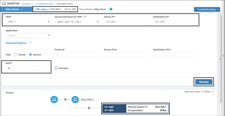
Figure 8-20 Validating App-Aware Routing with the Simulate Flows Tool
Continuing on with the sla-class REALTIME_SLA preferred-color mpls command and sequence 1 from the preceding policy in Example 8-3, if the MPLS color is out of compliance and other colors are in compliance, the traffic will be forwarded over those tunnels. This can be seen on the CLI using the show app-route stats command, as shown in Example 8-5.
Example 8-5 Observing Tunnel Compliance with Preferred Color Out of Compliance
BR2-vEdge-1# show app-route stats remote-system-ip 10.0.103.1
app-route statistics 100.64.102.2 100.64.103.2 ipsec 12346 12346
 remote-system-ip 10.0.103.1

 local-color      biz-internet
 remote-color     biz-internet
 mean-loss        0
 mean-latency     25
 mean-jitter      18
 sla-class-index  0,1,2,3

       TOTAL          AVERAGE  AVERAGE  TX DATA  RX DATA
INDEX  PACKETS  LOSS  LATENCY  JITTER   PKTS     PKTS
----------------------------------------------------------
0      10       0     62       34       0        0
1      10       0     11       17       0        0
2      10       0     3        2        0        0

<<<Omitted for Brevity>>>

app-route statistics 100.127.102.2 100.127.103.2 ipsec 12346 12346
 remote-system-ip 10.0.103.1
 local-color      lte
 remote-color     lte
 mean-loss        0
 mean-latency     10
 mean-jitter      13
 sla-class-index  0,1,2,3

       TOTAL          AVERAGE  AVERAGE  TX DATA  RX DATA
INDEX  PACKETS  LOSS  LATENCY  JITTER   PKTS     PKTS
----------------------------------------------------------
0      10       0     9        11       0        0
1      10       0     4        1        0        0
2      10       0     17       27       0        0

app-route statistics 172.16.102.2 172.16.103.2 ipsec 12346 12346
 remote-system-ip 10.0.103.1
 local-color      mpls
 remote-color     mpls
 mean-loss        6
 mean-latency     3
 mean-jitter      3
 sla-class-index  0,1

       TOTAL          AVERAGE  AVERAGE  TX DATA  RX DATA
INDEX  PACKETS  LOSS  LATENCY  JITTER   PKTS     PKTS
----------------------------------------------------------
0      10       2     2        2        0        0
1      10       0     4        6        0        0
2      10       0     2        1        0        0

BR2-vEdge-1#
As Example 8-5 shows, the Biz-Internet and LTE tunnels are still listed as in compliance with SLA Class Index 3 (REALTIME_SLA), but the MPLS tunnel at the end of the example is only compliant with SLA Class Index 0 (__all_tunnels__) and 1 (BULK_DATA_SLA). This is caused by the 6% mean packet loss on the MPLS tunnel. In this situation, DSCP 46 traffic will be forwarded across the Biz-Internet and LTE tunnels, as shown in Figure 8-21.

Figure 8-21 Validating App-Aware Routing with the Simulate Flows tool
Figure 8-21, which was created using the same criteria as Figure 8-20, illustrates that when the preferred color is not in compliance with the configured SLA class, then all of the available equal-cost tunnels that are in compliance with the SLA class will be used. In this case, there is a total of four different tunnels (the LTE TLOC is also building a tunnel to the receiving router’s Biz-Internet TLOC, and vice versa).
In the examples up to this point, the preferred-color [color] command has only specified a single color as the preferred color. However, administrators are able to configure multiple colors as arguments to this command. This functionality is demonstrated in sequence 21 of the App-Route policy shown in Example 8-3: sla-class CRITICAL_DATA_SLA preferred-color mpls biz-internet. In the case of multiple preferred colors, where multiple colors are in compliance, the traffic will be load-shared on a per-flow basis. In the case that multiple preferred colors are specified but only a single color is compliant, the traffic class will be forwarded across that color. As with Example 8-5, when none of the preferred colors is compliant with the SLA requirements, the traffic is forwarded across any of the nonpreferred colors that are compliant with the SLA class. Another variation of this configuration is where the SLA Class action is specified but no preferred color is specified. In this case, the traffic is load-shared per flow among all of the colors that meet the required SLA.
The last permutation to consider is the behavior of the sla-class command when none of the TLOCs meet the required SLA, as demonstrated in Example 8-6.
Example 8-6 Observing Tunnel Compliance with All Colors Out of Compliance
BR2-vEdge-1# show app-route stats remote-system-ip 10.0.103.1 | i app|sla|col
app-route statistics 100.64.102.2 100.64.103.2 ipsec 12366 12366
 local-color      biz-internet
 remote-color     biz-internet
 sla-class-index  0
app-route statistics 100.64.102.2 100.127.103.2 ipsec 12366 12366
 local-color      biz-internet
 remote-color     lte
 sla-class-index  0
app-route statistics 100.127.102.2 100.64.103.2 ipsec 12366 12366
 local-color      lte
 remote-color     biz-internet
 sla-class-index  0
app-route statistics 100.127.102.2 100.127.103.2 ipsec 12366 12366
 local-color      lte
 remote-color     lte
 sla-class-index  0
app-route statistics 172.16.102.2 172.16.103.2 ipsec 12366 12346
 local-color      mpls
 remote-color     mpls
 sla-class-index  0
BR2-vEdge-1#
When all of the tunnels are out of compliance with the configured SLA class, as indicated in Example 8-6, there are several different configuration options that will dictate the forwarding behavior. In the simplest use case, as seen in sequence 31 of Example 8-7, when there are no further configured actions beyond the sla-class action, the traffic is load-shared across all available transports.
Example 8-7 Configuration Options When SLA Class Cannot Be Honored
vSmart-1# show running-config policy

<<< Omitted>>>

app-route-policy _CorporateVPN_Expande_-170838785
  vpn-list CorporateVPN
   sequence 1
    match
     source-ip 0.0.0.0/0
     dscp      46
    !
    action
 ! When the backup-sla-preferred-color command is supplied, traffic is forwarded
 ! across that color or colors if no colors can meet the required SLA
     sla-class REALTIME_SLA preferred-color mpls
    backup-sla-preferred-color mpls
    !
   !
   sequence 11
    match
     source-ip 0.0.0.0/0
     app-list  REALTIME_DATA_TRANSFER
    !
    action
 ! When the strict command is supplied, traffic is forwarded across the
 ! preferred color if the preferred color is able to meet the SLA.  If the
 ! preferred color does not meet the SLA, but any other color does, the
 ! traffic will be forwarded on that tunnel.  If there are no colors that
 ! meet the required SLA, the traffic is dropped.
     sla-class CRITICAL_DATA_SLA strict preferred-color mpls
    !
<<< Omitted>>>
   !
   sequence 31
    match
     source-ip 0.0.0.0/0
     dscp      8
    !
    action
 ! When no other arguments are configured, and no colors meet the SLA, then the
 ! traffic is load shared per flow across all available paths.  This functionality
 ! is equivalent to not having an app-route policy configured.
    sla-class BULK_DATA_SLA preferred-color biz-internet
!
Two alternative configurations could be used in the event that none of the tunnels is able to meet the configured SLA: backup-sla-preferred-color and strict.
The backup-sla-preferred-color action specifies the color that the traffic should be forwarded across in the event that none of the colors is able to support the required SLA class. Sequence 1 in Example 8-7 illustrates the use of the backup-sla-preferred-color configuration option. While it might look strange at first glance to have the mpls color specified as both the preferred-color and the backup-sla-preferred-color, this is a rational and often used configuration choice. This configuration should be understood as follows:
If the MPLS tunnel meets the required SLA, then forward the traffic on the MPLS tunnel.
If the MPLS tunnel does not meet the required SLA but some other tunnel(s) do, then forward the traffic on the tunnels that meet the SLA.
If no tunnels meet the required SLA, then forward the traffic on the MPLS tunnel.
Sequence 1 in Example 8-7 would allow for the transmission of sensitive, real-time communications flows over the MPLS path, where we have an SLA agreement with the carrier, as long as that transport was performing to the required SLA. If the MPLS path was failing to meet the SLA but some other transport was able to meet the SLA, this sensitive traffic class would be forwarded over that path. In the event that no transports were able to meet the required SLAs (and the network administrators were having a really bad day), then the sensitive traffic classes would be transported over the MPLS path where there is a contractual SLA with the carrier, and hopefully service will be restored soon.
The last option with the SLA Class action is the strict command, as seen in sequence 11 of Example 8-7. The strict option specifies that if no colors are available that meet the required SLA class, the traffic should be dropped instead of forwarded. backup-sla-preferred-color and strict are logical opposites of each other. The backup-sla-preferred-color option specifies where to forward the traffic if no paths meet the required SLA. The strict option indicates that the traffic should be dropped if there is no path available that meets the required SLA. As such, these two options are mutually exclusive and cannot be configured at the same time.
Note
Though the strict command may have uses for very specific applications (such as SCADA networks, where timely delivery of monitoring traffic is critical), it is not an option that is commonly used by customers. Unfortunately, it tends to provide more confusion than value for most network administrators, and most customers are well served to steer clear of it.
Summary
This chapter has discussed the basics of building App-Route policies with Cisco SD-WAN. Every SD-WAN tunnel that is established in the data plane automatically starts to send BFD probes. These BFD probes serve two purposes: They are able to detect if the forwarding path between two WAN Edge routers is still valid, and they determine the loss latency and jitter conditions of that forwarding path. The information about the real-time condition of the transport paths can then be used to inform the forwarding process and ensure that business-critical applications are sent over paths that are able to meet the required service level agreements. Ultimately, this capability enables organizations to move away from their expensive, legacy transport providers and adopt commodity Internet circuits for transport while not having to compromise on application performance.
Review All Key Topics
Review the most important topics in the chapter, noted with the Key Topic icon in the outer margin of the page. Table 8-5 lists these key topics and the page numbers on which each is found.
Table 8-5 Key Topics
Key Topic Element |
Description |
Page |
|---|---|---|
Paragraph |
Ensure that there are enough BFD probes in a particular Poll Interval in order to generate statistically significant results. |
299 |
Paragraph |
Path condition will only be evaluated at the end of the App-Route Poll Interval. |
303 |
Paragraph |
An App-Route policy can only make forwarding decisions between equal-cost paths that are already installed in the routing table. |
305 |
Paragraph |
A vSmart policy can contain up to eight different SLA Class lists, but only four can be used on a single WAN Edge at any time. |
308 |
Define Key Terms
Define the following key terms from this chapter and check your answers in the glossary:
Chapter Review Questions
1. What is the scope of an Application-Aware Routing policy?
Per site
Per VPN
Per direction
Per site, per VPN
Per site, per direction
Per site, per VPN, per direction
2. Where are App-Route policies applied and enforced?
Applied on the vSmart; enforced on the vSmart
Applied on the vSmart; enforced on the WAN Edge
Applied on the WAN Edge; enforced on the vSmart
Applied on the WAN Edge; enforced on the WAN Edge
3. Which administratively configured options affect the calculation of the loss, latency, and jitter statistics used for Application-Aware Routing? (Select all that apply.)
BFD Hello Interval
BFD Hello Multiplier
Number of SLA Classes
App-Route Poll Interval
Number of Tunnels
Number of Colors
App Route Multiplier
4. What is the maximum number of App-Route Poll Intervals that can be used for tunnel performance calculations?
2
4
6
8
16
5. When are the tunnels (re)evaluated for compliance with the SLA classes?
After every BFD packet is received by the WAN Edge router
After every Hello Interval
After every Hello Multiplier
After every App-Route Poll Interval
6. How many different SLA classes can be applied to a single WAN Edge router?
2
4
8
256
Unlimited
7. How many different SLA classes can be configured in a vSmart policy?
2
4
8
256
Unlimited
8. When is traffic forwarded across the backup SLA preferred color?
No tunnels are configured or active with the preferred SLA color(s).
None of the preferred SLA color(s) are currently meeting the required SLA class.
No colors are currently meeting the required SLA class.
9. When configured, the “Strict” option in an AAR policy will drop the traffic if the preferred color(s) fails to meet the SLA Class requirements.
True
False
10. In order for an Application-Aware Routing policy to have any effect, there must be multiple equal-cost routes in the routing table.
True
False