
Chapter 6. Centralized Control Policies
This chapter covers the following topics:
Centralized Control Policy Overview: This section discusses the basics of centralized control policies and the directionality of policies when applied to a vSmart.
Use Case 1: Isolating Remote Branches from Each Other: This section covers the process of building and applying a centralized control policy as well as how to limit the data plane tunnels that are built in the SD-WAN fabric.
Use Case 2: Enabling Branch-to-Branch Communication Through Data Centers: This section covers the use of summarization and TLOC lists to enable sites that do not have direct data plane connectivity to still communicate.
Use Case 3: Traffic Engineering at Sites with Multiple Routers: This section covers the use of the TLOC Preference attribute to manipulate how traffic flows into sites with more than one WAN Edge.
Use Case 4: Preferring Regional Data Centers for Internet Access: This section covers the use of the OMP Route Preference attribute to perform traffic engineering on a per-prefix basis.
Use Case 5: Regional Mesh Networks: This section discusses how to create subsets of the fabric that have a full mesh of data plane connectivity, even while the whole fabric does not.
Use Case 6: Enforcing Security Perimeters with Service Insertion: This section covers the use of service insertion to be able to direct a flow from anywhere in the fabric to a local or remote service.
Use Case 7: Isolating Guest Users from the Corporate WAN: This section covers the use VPN Membership policies to be able to restrict which VPNs can join the overlay fabric.
Use Case 8: Creating Different Network Topologies per Segment: This section covers the use of control policies to create multiple, arbitrary topologies that can be applied on a per-VPN basis.
Use Case 9: Creating Extranets and Access to Shared Services: This section covers the construction of extranets to enable connectivity with business partners, while still maximizing security posture.
Network administrators can use centralized control policies to manipulate the way traffic flows throughout the Cisco SD-WAN fabric. Fundamentally, centralized control policies are the mechanism through which the control plane information that is advertised by the Overlay Management Protocol (OMP) between the vSmart controllers and WAN Edge routers is manipulated and/or filtered. By manipulating or filtering this information in the control plane, network administrators can influence the way that end-user traffic is forwarded in the data plane in order to accomplish their business objectives. This chapter explores several common business-relevant use cases, the network designs necessary to achieve them, and the centralized control policies used to implement them.
Centralized Control Policy Overview
Throughout the next several chapters, where we examine policies in Cisco SD-WAN, we will be using the topology illustrated in Figure 6-1.

Figure 6-1 Network Topology Overview
This simple network topology features two different data centers (DCs) and three branch sites. Each data center has both an MPLS transport and an Internet transport. The branches, in addition to having an MPLS and Internet transport, also have an LTE transport. The hostnames, Site IDs, Router IDs, and network prefixes are also seen in the diagram. The service-side addressing in this network follows the 10.X.Y.0/24 structure, where X signifies the service-side VPN, and Y signifies the Site ID. For the first few use cases in this chapter, we will be focusing on VPN 1. Therefore, all of the service-side addressing will be in the 10.1.Y.0/24 addressing blocks. The SD-WAN controllers and their System IPs are also indicated in this diagram. This topology will allow us to explore different types of policies, how they interact with the SD-WAN fabric, and how network administrators can apply these policies to solve business problems.
As discussed in Chapter 5, “Introduction to Cisco SD-WAN Policies,” each type of policy has a specific directionality to it. In the case of centralized control policies, policies can be applied in either the inbound or the outbound direction. This directionality is always from the perspective of the vSmart, as shown in Figure 6-2.
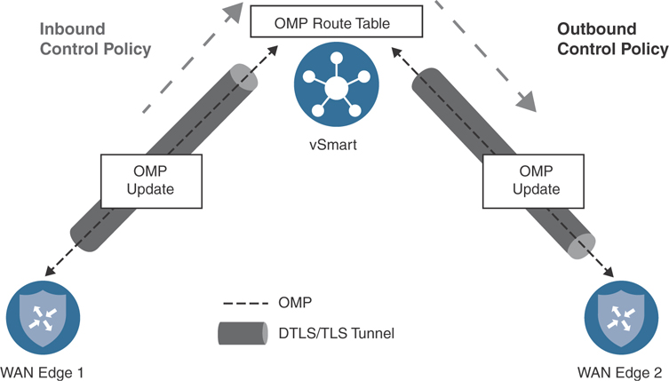
Figure 6-2 Inbound and Outbound Control Policies
Inbound policies are applied before the routes are processed through the best-path selection algorithm and before the routes are inserted into the OMP table on the vSmart. As such, any manipulation by inbound control policies will be evident in the vSmart best-path selection process and in turn evident in the OMP advertisements made to all of the other WAN Edge routers. Conversely, policies that are applied outbound are applied after the vSmart best-path selection process has been completed and are limited in scope to only those site IDs listed in the control policy application configuration. In this way, centralized control policies that are applied inbound tend to be much more global in nature, whereas outbound control policies can be much more limited and targeted in their scope and application.
In the following sections, we examine several different sets of business requirements and how network administrators can use centralized control policies to solve for these use cases. These use cases are meant to address common applications of centralized control policies as well as to provide an illustrative review of many of the building blocks of centralized control policies from which network administrators can build their own policies to accomplish their own objectives.
Use Case 1: Isolating Remote Branches from Each Other
The first use case we will be exploring is to turn the topology of the fabric from a full mesh into a hub-and-spoke design, with the data centers as hubs and the branch offices as spokes. Network designs like this are often used for several reasons: In many types of networks, particularly in retail and finance where security is a concern, there is little need to be able to communicate from one branch directly to another branch. As such, the structure of the network can be changed to reflect the desired traffic flow, and the business intent can be encoded directly into the SD-WAN fabric. Furthermore, if this is a large network consisting of hundreds or thousands of spokes, the devices deployed at the branch sites may not have the capacity to build tunnels to all of the other branch offices. In this way, the devices at the branch offices do not need to be sized to handle hundreds or thousands of IPsec tunnels.
As discussed in Chapter 3, “Control Plane and Data Plane Operations,” the default state of the Cisco SD-WAN fabric with no policies applied is a full mesh. That is, every WAN Edge router builds an IPsec tunnel to every other router that it has reachability to. In our sample network, since we have the “restrict” attribute set on the tunnel interfaces with the MPLS color, tunnels from the MPLS interfaces will only be built to the other MPLS interfaces. By contrast, tunnels from Biz-Internet will be built to both Biz-Internet and LTE interfaces on other routers. Tunnels from the LTE color will be built to both the Biz-Internet and LTE inter-faces on the other routers in the fabric. The result of this behavior (in this relatively simple network of only five sites and only eight routers) is the WAN Edge router at Branch 2 will build 27 different tunnels, as shown in the real-time output in Figure 6-3.

Figure 6-3 BR2-vEdge1 Tunnels with No Control Policy Applied
Note
The real-time output, as shown in Figure 6-3, is available in the vManage GUI by selecting Monitor > Network > [Device]. The Monitor > Network display can be used to track lots of information that administrators will find useful throughout the provisioning and operation of the SD-WAN fabric. The Real Time option can be found at the very bottom of the list of elements. Once the Real Time element is selected, the Device Options field at the top of the page can be used to query the device and display the output of practically any show command that would be used from the CLI interface. This feature is referred to as “Real Time” because it queries the device in real time and does not rely on cached data like many of the other elements in the Monitor section of vManage. For this reason, you might occasionally notice a slight delay, as vManage queries the device for the requested real-time output.
As discussed in Chapter 3, the process of building data plane tunnels is controlled by the advertisement of Transport Locators (TLOCs). If a WAN Edge receives a TLOC from the vSmart controller, it will attempt to build a data plane tunnel to that TLOC and establish a Bidirectional Forwarding Detection (BFD) session across the tunnel. As such, monitoring BFD sessions, as shown in Figure 6-3, is a good way to understand if tunnels are trying to be formed and whether they were formed successfully. To change this behavior in the data plane, you must filter which TLOCs are advertised from the vSmart to the WAN Edge routers.
If the BFD session is working as expected, and there is bidirectional data plane connectivity, the BFD session will be listed in the “Up” state. If the TLOC advertisement was received from the vSmart, but the data plane tunnel is unable to form correctly, the BFD session will be listed in the “Down” state. If the data plane tunnel does not appear in the list of BFD sessions, the WAN Edge is not attempting to build the data plane tunnel. This behavior is generally caused for one of two reasons: either the WAN Edge has not received the TLOC advertisement from the vSmart or the data plane tunnel is prohibited from being built by either the “restrict” or “tunnel-group” settings. Chapter 3 provides a deeper discussion of these settings.
The current state of the network can also be examined from the ways that traffic flows through the network. In Example 6-1, you can see that from Branch 2, the destination address 10.1.103.1 (which resides at Branch 3) is one hop away; that is, it is directly connected.
Example 6-1 Tracing from BR2-vEdge1 to BR3-cEdge1
Traceroute from BR2-vEdge1 to BR3-cEdge1:
! The traceroute is successful, and shows that the path is direct (1 hop)
BR2-vEdge-1# traceroute vpn 1 10.1.103.1
Traceroute  10.1.103.1 in VPN 1
traceroute to 10.1.103.1 (10.1.103.1), 30 hops max, 60 byte packets
 1  10.1.103.1 (10.1.103.1)  8.227 ms * *
!
! Traceroute from BR2-vEdge1 to DC1-vEdge1:
! The traceroute is successful; resources in the DC are also one hop away
BR2-vEdge-1# traceroute vpn 1 10.1.10.1
Traceroute  10.1.10.1 in VPN 1
traceroute to 10.1.10.1 (10.1.10.1), 30 hops max, 60 byte packets
 1  10.1.10.1 (10.1.10.1)  3.912 ms  5.534 ms  5.596 ms
BR2-vEdge-1#
In addition to the prefixes at Branch 3, Example 6-1 also shows that the prefixes in the data center are reachable in one hop. This is also reflected in the routing table, as shown with the real-time output, where the prefix 10.1.103.0/24 is reachable with a TLOC IP of 10.0.103.1 (the system IP of BR3-cEdge1, as shown in Figure 6-1) and prefix 10.1.10.0/30 is reachable with a TLOC IP of 10.0.10.1 (the system IP of DC1-vEdge1), as shown in Figure 6-4.
In order to implement the business intent to eliminate branch-to-branch communication and to reduce the number of tunnels that are established, a centralized policy can be created and applied so that the branches will only build tunnels with the data center WAN Edges. As each WAN Edge router will attempt to build tunnels to all of the TLOCs that it receives from the vSmart controller, such a policy is architected to restrict the TLOCs that are advertised to the branches to be only the TLOCs from the DCs (where the branches should still build their control connections). Figure 6-5 illustrates this process.

Figure 6-4 Routing Table for VPN 1 on BR2-vEdge1 with No Centralized Policy Applied
In Step 1 of Figure 6-5, all of the WAN Edge routers advertise their local TLOCs to the vSmart controllers. In Step 2, the vSmarts advertise all of the received TLOCs back to all of the WAN Edges. For the DC WAN Edge, this means that the router receives all of the TLOCs in the vSmart table, including a copy of its own TLOCs. For Branch 1 and Branch 2, an outbound control policy is applied that restricts the advertisement of the TLOCs to only T1 and T2, which were learned from the data center. Note that the advertisements the data center WAN Edge receives in Step 2 contains all of the TLOCs in the network {T1, T2, T3, T4, T5, T6}, which is different from the TLOCs received by the branches. The outbound control policy has limited the TLOCs that are advertised to the branches to only {T1, T2}, the TLOCs from the data center. The effect of this policy can be seen in Step 3, when the data plane tunnels are built: All of the WAN Edge routers will build data plane tunnels to all of the TLOCs that they have received from the vSmarts. For the data center WAN Edge, this means that tunnels will be built to T3, T4, T5, and T6, the TLOCs of the branch routers. For the branches, tunnels will only be built to T1 and T2, the data center. Note that there is no tunnel built from T3 to T5, or from T4 to T6 in Figure 6-5. Since the WAN Edge router at Branch 1 never received an advertisement for T5 and T6, it is unaware of those TLOCs and will not attempt to build those tunnels. Manipulating and restricting the advertised TLOCs, as shown in Figure 6-5, is the fundamental way to control which data plane tunnels are built in the SD-WAN fabric, and as such, the primary way that network administrators control the structure of the fabric.

Figure 6-5 Illustration of Control Policies Filter TLOCs
Note
For the first two policy examples in this chapter, screenshots of the process to build and modify the necessary policies will be provided. For brevity, the remaining policies in this chapter will be provided only with the CLI output. There is no difference in the effect of the policy if it is built with the GUI or with the CLI.
The first step in constructing such a policy would be to open the new Policy Wizard by clicking Add Policy from the Configuration > Policies screen in vManage, as shown in Figure 6-6.
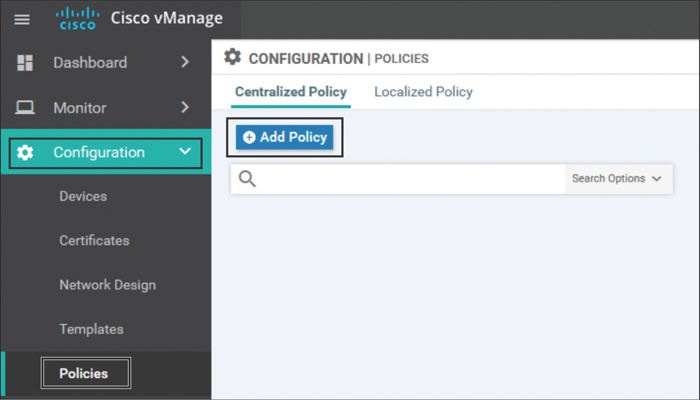
Figure 6-6 Opening the New Policy Wizard
From inside of the New Policy Wizard, the first option is to configure all of the criteria (Lists) that will be used within this policy. For this first use case, we will need to create two site lists: one that encompasses the site IDs of the data centers and a second that encompasses the site IDs of the branch offices. You can see these two lists in Figure 6-7. The ranges of site IDs configured in these lists reflect the ranges of site IDs identified in the network topology, as shown in Figure 6-1.
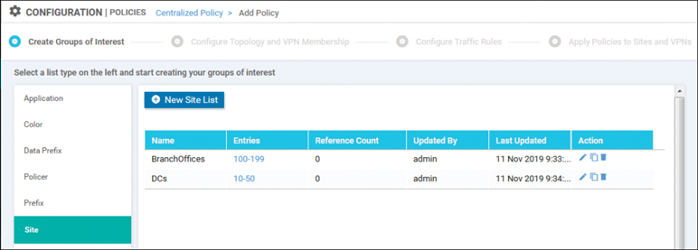
Figure 6-7 Configuring Site Lists for Use in Centralized Policies
After we click the Next button at the bottom of the Lists page, the wizard moves to the Configure Topology and VPN Membership page. From this page, click the Add Topology drop-down and select Custom Control (Route & TLOC) from the combo box, as shown in Figure 6-8.

Figure 6-8 Creating a Custom Control Policy
Note
The vManage GUI includes wizards to build hub-and-spoke and mesh topologies, as can be seen in Figure 6-8. While some network administrators find these assisted workflows easier to use, this chapter will focus on custom control policies to better illustrate the construction of the policies and the principles behind their use.
The first pieces of configuration necessary for every control policy are the policy name and description, as shown in Figure 6-9.

Figure 6-9 Setting the Default Action in the Control Policy
It is also important to notice in Figure 6-9 the default action in custom route and TLOC policies: Reject. If an OMP route or a TLOC is not matched by any other sequence in the policy and explicitly permitted, it will not be advertised from the vSmart to the WAN Edge router.
Next, click the Sequence Type button and choose a TLOC sequence, as shown in Figure 6-10.
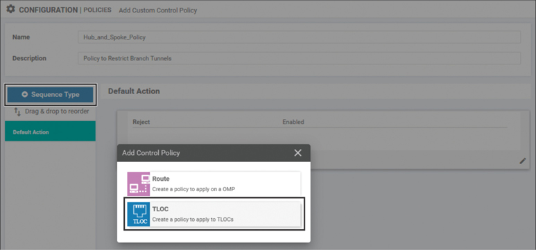
Figure 6-10 Adding a TLOC Sequence to a Centralized Control Policy
Next, create a new rule in the policy by selecting the + Sequence Rule option. In this sequence, specify a match criteria of a site list and match on the list called “DCs,” created previously. Lastly, specify the action Accept with no further actions and then Save Match and Actions, as shown in Figure 6-11.

Figure 6-11 Creating a TLOC Sequence Rule to Accept the DC TLOCs
This TLOC sequence rule, in combination with the default rule that rejects anything not explicitly permitted, will result in only the DC TLOCs (that is, only the TLOCs from sites specified in the site list “DCs”) being advertised to the sites where this policy is applied. Now that the TLOCs from the branch sites have been implicitly filtered, the network will have a topology analogous to what was displayed in Figure 6-5, and data plane tunnels will not form between the branch sites. However, as shown in Figure 6-4, the OMP routes for all of the prefixes that exist at all of the branch sites will still be reflected to all of the other branch sites. Without having received the necessary TLOC advertisements, these OMP routes will be unresolvable and unused, but bandwidth and compute resources will be wasted in transmitting these network updates.
Rather than continue to transmit routes that cannot be used, a better practice would be to filter out the routes from the branch sites in addition to the TLOCs. In order to accomplish this, select the + Sequence Type button and choose Route, as shown in Figure 6-12.
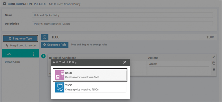
Figure 6-12 Adding a Route Sequence to a Centralized Control Policy
In a similar manner as was done for the TLOCs, the route sequence needs to be configured to match on the routes from the site list “DCs” and to accept them. No other sequences need to be configured at this time. You can see this configuration in Figure 6-13.

Figure 6-13 Creating a Route Sequence Rule to Accept the DC Routes
After the route sequence rule is saved by selecting the Save Match and Actions button, the entire policy can be saved by selecting the Save Control Policy button at the bottom. Once the control policy is saved, you can progress through the SD-WAN Policy Wizard by clicking Next through the Configure Topology and VPN Membership and Configure Traffic Rules screens, until arriving at the Apply Policies to Sites and VPNs screen, as shown in Figure 6-14. On this page, a name and description will need to be configured for the policy. Additionally, under the Topology tab, you must specify where and in what direction the recently created Hub_And_Spoke_Policy should be applied. In this example, the policy will be applied outbound to the branch offices.

Figure 6-14 Adding Policies to Sites and VPNs
Note
It is the author’s recommendation to simply name the centralized policies with version numbers. In this case, the name “Centralized_Policy_v1” was used as the policy name. As discussed in Chapter 5, there will only ever be a single centralized policy that is active at any point in time. From an operational view, it is easy to copy the existing centralized policy, increment the policy number, and then use the Policy Description field to list the changes from the previous version of the policy. This allows for an archive of the policies to be created on vManage. This way, should there ever be a need to roll back a change in the network, the process is as simple as activating a previous version of the policy.
Once the site list the policy is to be applied to is saved by clicking the Add button, you can see the CLI of the entire policy by clicking the Preview button. Example 6-2 shows the full output of this policy.
Example 6-2 Use Case 1: Complete Centralized Policy to Create Hub-and-Spoke Topology
policy
 control-policy Hub_and_Spoke_Policy
    sequence 1
     match tloc
      site-list DCs
     !
     action accept
     !
    !
! The reference to the prefix list below was not configured,
! but instead was added automatically by vManage. The matching
! logic remains the same: Match all Routes.
    sequence 11
     match route
      site-list DCs
      prefix-list _AnyIpv4PrefixList
     !
     action accept
     !
    !
  default-action reject
 !
 lists
  site-list BranchOffices
   site-id 100-199
  !
! Only Routes and TLOCs that match this site list will be advertised
! by the policy above.
  site-list DCs
   site-id 10-50
  !
  prefix-list _AnyIpv4PrefixList
   ip-prefix 0.0.0.0/0 le 32
  !
 !
!
! The policy is applied in the outbound direction to the sites that
! match the site list “BranchOffices”.
apply-policy
 site-list BranchOffices
  control-policy Hub_and_Spoke_Policy out
 !
!
The policy can then be saved by clicking the Save Policy button at the bottom of the page with the configuration preview. Once the policy is saved, it can be applied to the SD-WAN fabric by selecting the Activate option from the policy menu, as shown in Figure 6-15. As discussed in Chapter 5, the process of activating a policy is where vManage writes the policy into the configuration of the vSmarts.

Figure 6-15 Activating a Centralized Policy
Note
As configuring policy on a vSmart from vManage is actually manipulating the configuration of the vSmart itself, the vSmart controllers must be in “vManaged mode” and have a template applied from vManage. This allows vManage to have authoritative control of the vSmart configuration.
Once the policy has been applied, the effects of the policy can be seen using the same monitoring techniques observed before the policies were applied. From Monitor > Network > BR2-vEdge1 > Real Time, we can see the current list of BFD sessions, as shown in Figure 6-16. When Figure 6-16 is compared to the output observed before the policy was applied in Figure 6-3, we can see that the policy resulted in the number of BFD sessions (and IPsec tunnels) decreasing from 27 to 12. Furthermore, careful observation of Figure 6-16 shows that all of the remaining BFD sessions come from routers with System IPs of 10.0.10.1, 10.0.10.2, 10.0.20.1, or 10.0.20.2 (routers in Data Center 1 or Data Center 2). All of these tunnels are also established to sites with either Site ID 10 or 20.
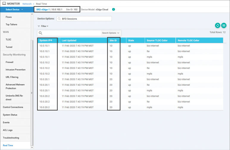
Figure 6-16 BR2-vEdge1 BFD Sessions after the Hub-and-Spoke Policy Is Applied
Before the policy was applied, we saw in Example 6-1 that we were able to run a traceroute from Branch 2 to Branch 3 in one hop. Now, when the same traceroute is run from BR2-vEdge1, we can see that the network is unreachable, as signified by the “!N” response from the local host in output of the traceroute command in Example 6-3.
Example 6-3 Network Unreachable When Tracing from BR2-vEdge1 to BR3-cEdge1
! Traceroute from BR2-vEdge1 to BR3-cEdge1:
! The traceroute is unsuccessful based on the “!N” (Network Unreachable)
! message being received from 127.1.0.2 (local host)
BR2-vEdge-1# traceroute vpn 1 10.1.103.1
Traceroute  10.1.103.1 in VPN 1
traceroute to 10.1.103.1 (10.1.103.1), 30 hops max, 60 byte packets
 1  127.1.0.2 (127.1.0.2)  0.042 ms !N  0.049 ms !N  0.047 ms !N
!
! Traceroute from BR2-vEdge1 to DC1-vEdge1:
! The traceroute is successful; resources in the DC remain reachable
BR2-vEdge-1# traceroute vpn 1 10.1.10.1
Traceroute  10.1.10.1 in VPN 1
traceroute to 10.1.10.1 (10.1.10.1), 30 hops max, 60 byte packets
 1  10.1.10.1 (10.1.10.1)  3.912 ms  5.534 ms  5.596 ms
BR2-vEdge-1#
The second traceroute to the data center remains successful after the policy has been applied. This behavior can be further explained by examining the IP Routes table in the Real Time output of BR2-vEdge1. As shown in Figure 6-17, after filtering for routes only in VPN 1, we can see that the branch office no longer has a route for the 10.1.103.0/24 prefix, and therefore the network is listed as unreachable. The only routes that remain in the VPN 1 routing table on BR2-vEdge1 are the routes with prefixes 10.1.10.X and 10.1.20.X that originate in the data centers (Site ID 10 and Site ID 20), other than the locally connected route 10.1.102.0/30.
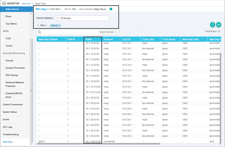
Figure 6-17 BR2-vEdge1 Routing Table after Policy Is Applied
Use Case 1 Review
In this use case, we used centralized control policies to prohibit site-to-site communication between branch locations. By encoding the business intent in this fashion into the structure of the SD-WAN fabric, we are able to harden the security posture of the network by preventing unintended east-west traffic flows between branch sites.
Use Case 2: Enabling Branch-to-Branch Communication Through Data Centers
In the previous use case, we saw how centralized control policies can be used to completely isolate branch sites from each other. While this may be appropriate for some use cases where no communication is preferred, there are also use cases where organizations may want to enable site-to-site communications indirectly by proxying traffic through a data center or some other regional hub. This can have the benefits of reducing complexity and scale of the control and data planes at the network edge, while still maintaining full connectivity for the occasional traffic flows that may need to exist between branch locations. There are two different potential solutions we will explore for this use case: summarization and TLOC lists.
Enabling Branch-to-Branch Communication with Summarization
Using summarization, in addition to the centralized control policy discussed in the previous use case, builds on the principle of longest-match routing and is not specific to any technology in Cisco SD-WAN. If a network summary, such as 10.0.0.0/8, or the default route (0.0.0.0/0) was advertised from the DC routers, then traffic would follow the path to the data center WAN Edge routers. The data center routers would then examine their routing tables and follow the route to the more specific match that was advertised from the branch sites. This is a common design mechanism that is used in hub-and-spoke WAN deployments such as with DMVPN Phase 1. Figure 6-18 illustrates this process.

Figure 6-18 Enabling Branch-to-Branch Communication with Summarization
As shown in Figure 6-18, when the WAN Edge in Branch 2 does a routing lookup in order to forward a packet to the destination 10.1.103.1, the most specific match in the routing table is the default route. The default route is being advertised from the WAN Edge router in the data center with a System IP of 10.0.10.1, so the packet is forwarded to that router. When the packet arrives at the DC router, it performs a lookup on the destination 10.1.103.1 in its own routing table. As the DC router has not had any routes or TLOCs filtered, it has a more specific route to 10.1.103.1 via 10.0.103.1 and forwards the packet along to Branch 3. In this way, communication is able to be established through the data centers by injecting a default or summary route, without needing to change the SD-WAN fabric or any policies.
For this use case, we have injected a default route in Data Center 1 that is being advertised by DC1-vEdge1 and DC1-vEdge2. The specific method used to inject the default route is unimportant. If you have a default route in the routing protocol running in the data center, it can be advertised directly into OMP. Alternatively, you can configure a static default route and advertise that into OMP. Regardless of the method used, once the default route is advertised into OMP, it is then propagated to the branch offices, as seen in Figure 6-19.

Figure 6-19 BR2-vEdge1 Routing Table with Default Route
With the default routes in place, traffic can now be forwarded to the data center and then to a different branch site, as shown in Example 6-4.
Example 6-4 Tracing from BR2-vEdge1 to BR3-cEdge1 Is Successful with Two Hops
! Traceroute from BR2-vEdge1 to BR3-cEdge1:
! The traceroute is successful, but requires two hops.  The intermediary hop,
! identified by the system ip of 10.1.10.1, is the DC1-vEdge1 router.
BR2-vEdge-1# traceroute vpn 1 10.1.103.1
Traceroute  10.1.103.1 in VPN 1
traceroute to 10.1.103.1 (10.1.103.1), 30 hops max, 60 byte packets
 1  10.1.10.1 (10.1.10.1)  104.163 ms  104.833 ms  105.491 ms
 2  10.1.103.1 (10.1.103.1)  125.817 ms * *
!
! Note that no changes have been made to the centralized control policy that was
! deployed for Use Case 1, and the number of data plane tunnels has not changed.
BR2-vEdge-1# show bfd summary
sessions-total         12
sessions-up            12
sessions-max           27
sessions-flap          15
poll-interval          10000
It is important to remember that no changes have been made to the centralized control policy applied for Use Case 1. The show bfd summary output in Example 6-4 indicates that there are still 12 BFD sessions (and 12 tunnels) established. This confirms that there are the same number of tunnels as displayed in Figure 6-16, and no new tunnels are established directly between the branches.
Enabling Branch-to-Branch Communication with TLOC Lists
Rather than injecting routes into the Cisco SD-WAN overlay to solve for the desired branch-to-branch communication pattern, it is possible to manipulate the routes that already exist in the overlay to accomplish the same objective.
As discussed in Chapter 3, a Transport Locator (TLOC) serves to uniquely identify the SD-WAN tunnel interfaces in the SD-WAN fabric and also serves as the next-hop attribute that all OMP and Network Service routes use within the overlay. When routes are advertised by the WAN Edge routers to the vSmart (and propagated by the vSmart to the other WAN Edge routers), each OMP route is advertised with the local TLOCs as the next-hop values, as illustrated in Figure 6-20. In Step 1, all of the WAN Edge routers advertise all of their locally reachable prefixes to the vSmart controller with OMP updates. In Step 2, the vSmart controller reflects all of these prefixes to all of the other WAN Edge routers, using TLOC values as the next-hop addresses.

Figure 6-20 OMP Routes with Next-Hop TLOCs Reflected Through the vSmart
A centralized control policy can be used to manipulate the TLOC attributes that are advertised as part of the OMP routes and, in effect, change the “next-hop address” that the OMP routes recurse to. Through this process, centralized control policies can be a very powerful tool to perform traffic engineering across the SD-WAN fabric. At the same time, this process maintains simplicity by only having to apply the policy from a single location: the vSmart.
In order to permit the branch-to-branch communication via the data centers without the need for injecting a default route, the policy from Use Case 1 (as shown in Example 6-2) will be modified slightly so that instead of dropping the routes from the other branches, the routes are instead advertised with new TLOCs: the TLOCs of the DC1 WAN Edge routers. Figure 6-21 illustrates the effect of this policy for the routes advertised from Branch 3.
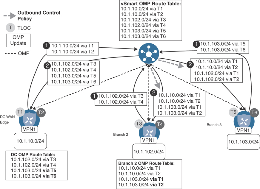
Figure 6-21 Enabling Branch-to-Branch Communication with TLOC Manipulation
Figure 6-21 builds on the route exchange process that was discussed in Figure 6-20. In the first step, all of the WAN Edge routers advertise their locally connected prefixes to the vSmart controllers. In the case of Branch 3, this means that the prefix 10.1.103.0/24 in VPN 1 is advertised via OMP as being reachable via TLOCs T5 and T6. The result of this advertisement can be seen in the vSmart OMP table. In Step 2, this advertisement is reflected to the data center routers as is; no manipulation is performed on the advertisement. However, when the route is reflected to the Branch 2 WAN Edge router, an outbound centralized control policy is applied and the TLOCs (next-hop addresses) are overwritten from the original values of T5 and T6 (the TLOCs of the WAN Edge at Branch 3) to TLOCs T1 and T2 (the TLOCs of the data center WAN Edge).
Note
Throughout the next several pages, the detailed process of modifying an existing centralized policy will be reviewed. This section will show the necessary steps in order to create a copy of the policies created in the previous use case and then modify them to meet the requirements of this use case. This same process can be used to construct the policies used throughout the other use cases in this book, but configuration steps in the vManage GUI will not be covered to the same degree of detail as was done in Use Case 1 and Use Case 2.
To begin to construct this policy in the vManage GUI, the first step is to create the new list element that will be needed: a TLOC list. To start this configuration, select the Lists item from the Custom Options menu on the Configuration > Policies window, as shown in Figure 6-22.
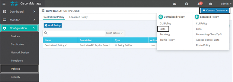
Figure 6-22 Accessing the Lists Configuration for Centralized Policies
To add a new TLOC list, select TLOC from the column of list types on the left and then click the +New TLOC List button, as shown in Figure 6-23.
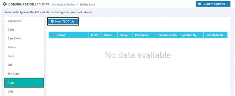
Figure 6-23 Creating a New TLOC List
In Figure 6-24, a TLOC list is configured with the name DC_TLOCs. There are a total of four TLOCs specified in the TLOC list: the mpls and biz-internet TLOCs on both DC1-vEdge1 and DC1-vEdge2. Recall from Chapter 3 that each TLOC is a unique combination of the System IP, the color, and the encapsulation. In addition to specifying these three required values, an optional argument of preference can be used to specify different TLOC preference values. This optional attribute was not used in this example and will be discussed in later use cases. Once the list is configured, it can be saved and closed by clicking the Save button.

Figure 6-24 Creating the TLOC List DC_TLOCs
The next step in the configuration process is to create the necessary centralized control policy to use the TLOC list. In order to do this, select the Topology option from the Custom Options menu in the upper-left corner, as shown in Figure 6-25.
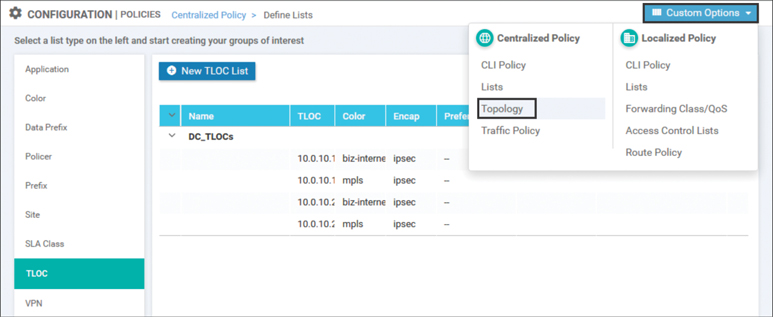
Figure 6-25 Selecting Topology from the Custom Options Menu
In order to copy the existing policy that was created in Use Case 1 so that it can be modified, select the … menu next to the policy and click Copy, as shown in Figure 6-26.

Figure 6-26 Creating a Copy of an Existing Centralized Control Policy
Every policy is required to be configured with a name and a description. The name and the description for the newly copied policy are shown in Figure 6-27. In this case, the new centralized control policy is named Hub_and_Spoke_TLOC_Lists.
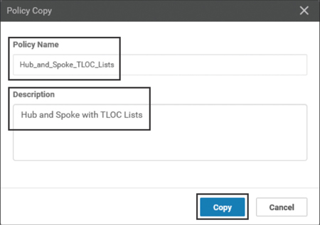
Figure 6-27 Providing a Name and a Description for the Newly Copied Policy
Now that the new copy of centralized control policy has been created from the original policy in Use Case 1, the policy can be edited by selecting the Edit option from the … menu, as shown in Figure 6-28.
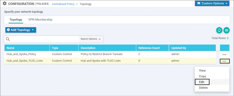
Figure 6-28 Editing the Newly Copied Centralized Control Policy
This policy needs to be altered such that the routes that are originating from the branch sites are rewritten to resolve to the new DC_TLOCs list that was previously created, as shown in Figure 6-29. In order to accomplish this, select the existing Route sequence type on the far left that is highlighted in green in the GUI. Then, click the + Sequence Rule to add a new sequence rule. In this sequence rule, the matching criteria is configured as the BranchOffices site list that was created in the previous use case by clicking the Match sub-tab, selecting the Site criterion, and then adding the necessary site list (not pictured). Once the matching criteria are specified, select the Actions tab at the top of the sequence rule and select the Accept radio button. Once the routes are accepted, the TLOC action can now be selected and the previously created TLOC list DC_TLOCs can be specified. Once all of the configuration is completed, select the blue Save Match and Actions button at the bottom of the sequence rule.
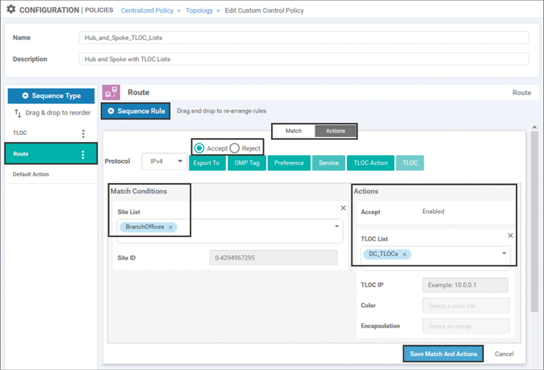
Figure 6-29 Creating a New Sequence to Manipulate Routes Advertised from Branch Sites
The completed policy with both the existing route sequence rule from the previous use case and the newly created route sequence rule can be seen in Figure 6-30. In summary, the first sequence rule of this policy will match all of the routes being advertised from the DCs and forward them on without any modifications. The second sequence will match all of the routes being advertised from other branches and change their TLOCs (or next-hop attributes) to be the TLOCs of the data centers. The completed policy is saved by selecting the blue Save Control Policy button at the bottom.
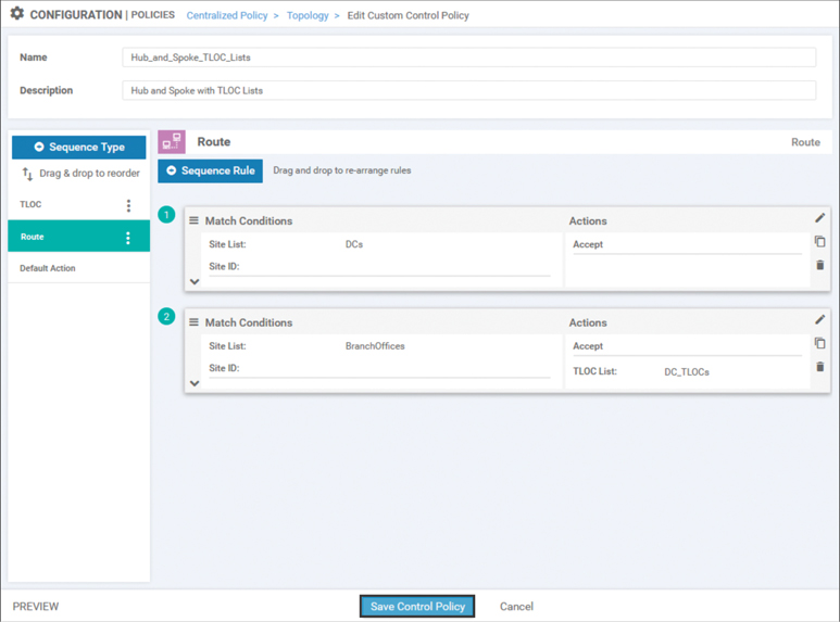
Figure 6-30 Saving the Centralized Control Policy with Two Route Sequences
Now that the centralized control policy has been created, it needs to be imported into a centralized policy. To do this, return back to the main Centralized Policy Configuration screen by clicking on Centralized Policy in the breadcrumb trail across the top of the screen, as shown in Figure 6-31.

Figure 6-31 Navigating Back to the Centralized Policy Configuration Screen Using the Breadcrumb Trail
The next step in the configuration process is to create a copy of the centralized policy that was created in Use Case 1, which will then be modified. As shown in Figure 6-32, this is done by selecting the … menu and selecting the Copy option.
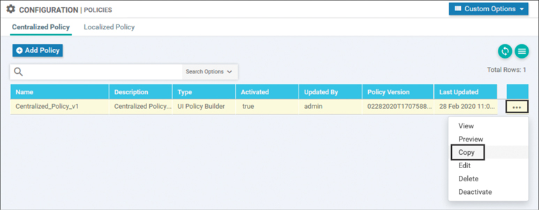
Figure 6-32 Creating a Copy of a Centralized Policy Before Starting Modifications
In order to copy the policy, a name and description must be supplied, as shown in Figure 6-33. Once these values are supplied, click the Copy button to complete the process.
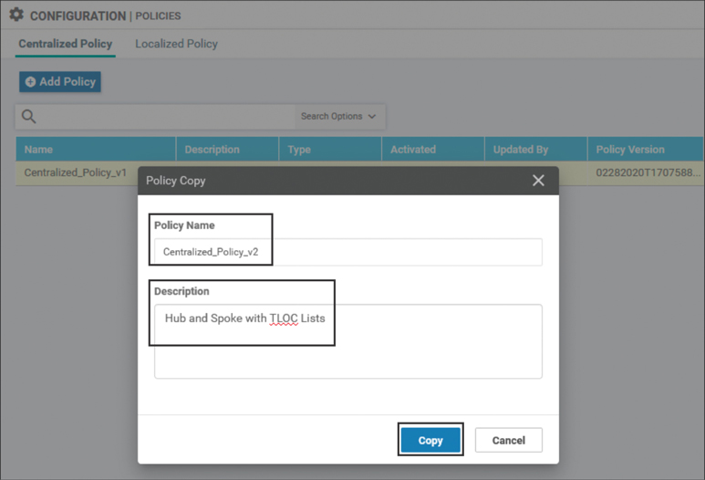
Figure 6-33 Configuring a Name and Description for the Copied Centralized Policy
Figures 6-32 and 6-33 complete the process of copying the centralized policy. This process for copying the centralized policy is the analogue of the steps taken in Figures 6-26 and 6-27 for copying the centralized control policy. In both cases, it would have been possible to modify the existing policies rather than copy them and modify the copies. This process, as illustrated, is considered a best practice, helps to avoid inadvertently applying configuration to the network, and aids in quickly rolling back any configuration changes should the need arise.
Now that Centralized_Policy_v2 has been created, it can be modified to use the new control policy with the TLOC list by clicking the Edit option from the … menu, as shown in Figure 6-34.
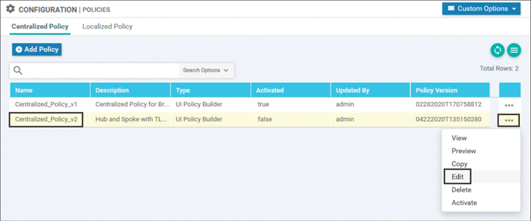
Figure 6-34 Editing a Centralized Policy
In order to modify this centralized policy for Use Case 2, several changes will need to be made. The centralized control policy created in Use Case 1 will need to be detached from this policy, and the new centralized control policy that was created in Figures 6-26 through 6-30 will need to be imported into this centralized policy. Finally, that new policy will have to be applied to the branch sites. In order to begin with detaching the old centralized control policy, click on the Topology tab at the top of the window, as shown in Figure 6-35. On the Topology tab, the Topology sub-tab is already selected and the centralized control policies that are referenced by this centralized policy are listed. Note that there is also a VPN Membership sub-tab that will be used in later use cases. Select the Detach option from the … menu on the Hub_and_Spoke_Policy in order to detach this control policy from Use Case 1.

Figure 6-35 Detaching an Unnecessary Centralized Control Policy from a Centralized Policy
Next, the newly created centralized control policy will need to be attached to this policy by clicking the + Add Topology button and then selecting the Import Existing Topology option, as shown in Figure 6-36.

Figure 6-36 Importing an Existing Control Policy into a Centralized Policy
With the Import Existing Topology dialog box, select the radio button for Custom Control (Route and TLOC) under Policy Type and then select the name of the new centralized control policy Hub_163and_Spoke_TLOC_Lists from the Policy drop-down. Complete the process by clicking the blue Import button, as shown in Figure 6-37.

Figure 6-37 Selecting the Existing Control Policy to Import into a Centralized Policy
Now that the new centralized control policy has been imported into the centralized policy, the last part of the configuration process is to specify where this policy should be applied. To start this process, move back to the Policy Application page by clicking that tab at the top of the window. The Topology sub-tab is selected by default and lists all of the control policies in this centralized policy. The other sub-tabs will be used in later chapters with Application-Aware Routing and centralized data policies.
Under the Hub_and_Spoke_TLOC_Lists policy, select the blue + New Site List button in order to specify the site lists that this policy should be applied to. Add the BranchOffices site list to the Outbound Site List field. The final step in saving the policy application configuration is to click the Add button on the right side and then click the Save Policy Changes button at the bottom, as shown in Figure 6-38.
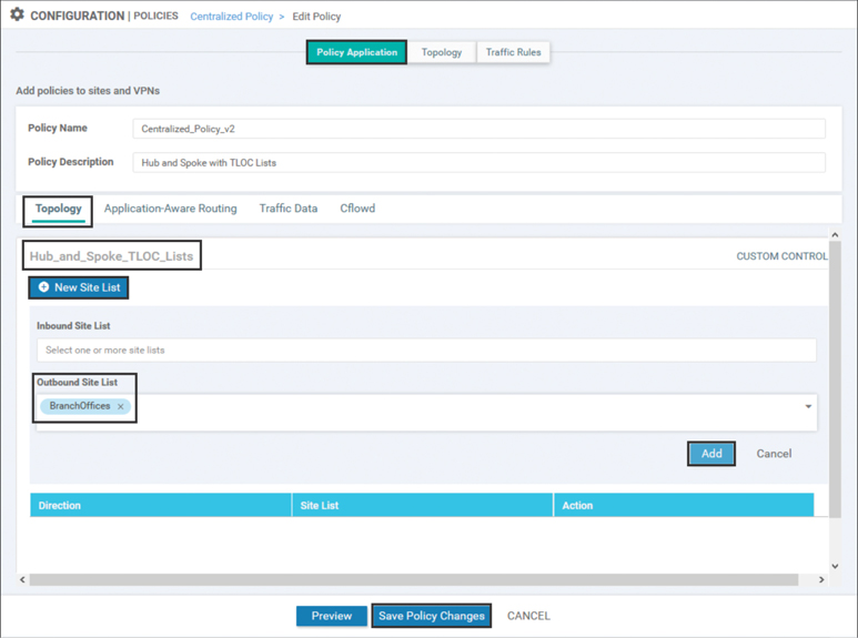
Figure 6-38 Configuring the Policy Application for the Imported Control Policy in a Centralized Policy
The new centralized control policy has now been saved and can be activated by selecting the Activate option from the … menu, as shown in Figure 6-39. There is no need to deactivate Centralized_Policy_v1 before the new policy is activated. As there can only be a single centralized policy that is active at any point in time, activating the new policy automatically deactivates any other policy.
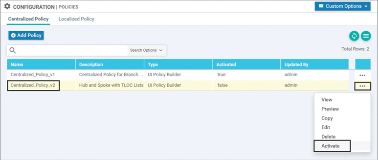
Figure 6-39 Activating a Centralized Policy
The full CLI configuration of the policy is also visible by selecting the Preview option from the … menu in Figure 6-39. The output of the policy preview displayed in Example 6-5 shows the complete centralized policy used to implement the objectives of this use case.
Example 6-5 Use Case 2: Hub-and-Spoke Policy with TLOC Lists
! Much of the centralized policy is unchanged from Example 6-2.
! The relevant changes in sequence 21 and the lists are highlighted below.
policy
 control-policy Hub_and_Spoke_TLOC_Lists
    sequence 1
     match tloc
      site-list DCs
     !
     action accept
     !
    !
    sequence 11
     match route
      site-list DCs
      prefix-list _AnyIpv4PrefixList
     !
     action accept
     !
    !
! The new sequence 21 has been added to permit the routes that are
! advertised from the branches, and advertise them with new TLOCs that are
! specified by the “DC_TLOCs” argument to the tloc-list command.
   sequence 21
    match route
     site-list BranchOffices
     prefix-list _AnyIpv4PrefixList
     !
     action accept
      set
       tloc-list DC_TLOCs
      !
     !
    !
  default-action reject
 !
 lists
  site-list BranchOffices
   site-id 100-199
  !
  site-list DCs
   site-id 10-50
  !
! A new list called “DC_TLOCs” is used to specify which TLOCs should be
! advertised as the next hop addresses of the routes.
  tloc-list DC_TLOCs
   tloc 10.0.10.1 color mpls encap ipsec
   tloc 10.0.10.1 color biz-internet encap ipsec
   tloc 10.0.10.2 color mpls encap ipsec
   tloc 10.0.10.2 color biz-internet encap ipsec
  !
  prefix-list _AnyIpv4PrefixList
   ip-prefix 0.0.0.0/0 le 32
  !
 !
!
apply-policy
 site-list BranchOffices
  control-policy Hub_and_Spoke_TLOC_Lists out
 !
!
Example 6-5 shows the command line configuration for the TLOC list that was configured in Figure 6-24. The TLOC list is established with the command tloc-list {list-name}. Once the list is created, each TLOC much be specified individually with the following syntax:
tloc {system-ip} color {color} encap {ipsec|gre} [preference preference]
[weight weight]
These configuration commands reflect the configuration that was performed in vManage in Figure 6-24. The TLOC list is then referenced in Sequence 21 of the control policy to overwrite the existing TLOC attributes that would have been advertised with the OMP routes from the branch sites. Lastly, the final stanza in Example 6-5 shows that the policy is applied to the site list BranchOffices in the outbound (out) direction.
With this new centralized policy applied, we can see the effect by looking at the routing table, as shown in Figure 6-40. In the IP routing table, we can see that we now have four different paths to the prefix 10.1.103.0/24. Careful inspection of those advertisements reveals that the TLOC IP address is not 10.0.103.1 as it was in Figure 6-4 when there was no control policy applied. Instead, it is now listed as 10.0.10.1 and 10.0.10.2, the TLOC IPs of the WAN Edge routers in DC1, as specified in the TLOC list.

Figure 6-40 Routing Table on BR2-vEdge1
It is also important to consider what effect the policy had on the routes that have been advertised to the data center. We can examine the IP routes output from the Real Time view, as shown in Figure 6-41, and see that the routes are received by the DC1-vEdge1 router with all of the original TLOC advertisements.
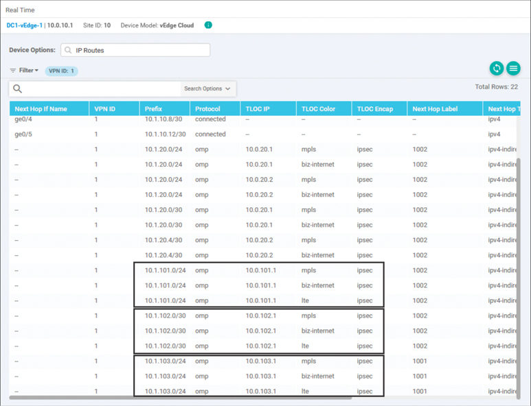
Figure 6-41 Routing Table on DC1-vEdge1
As shown in Figure 6-41, the data center routing table entries for the prefixes from the branches are specified with the original TLOC IPs as the next-hop values. When Figure 6-41 is compared to Figure 6-40, it is clear that there are different TLOC IPs, or next-hop attributes, that are advertised to the branch WAN Edge than are advertised to the data center WAN Edge. This is expected because the route manipulation is happening outbound to the WAN Edges covered under the BranchOffices site list. There is no manipulation happening on the OMP advertisements being sent to the data center WAN Edge routers.
Furthermore, a traceroute from the Branch 2 WAN Edge router is able to confirm that the data plane is working as expected, as seen in Example 6-6.
Example 6-6 BR2-vEdge1 Is Able to Access the Prefixes in Another Branch by Transiting the Data Center
! BR2-vEdge1 is able to reach the destination 10.1.103.1, but the path requires
! two hops, and must transit through the DC WAN Edge Routers (10.1.10.1).
BR2-vEdge-1# traceroute vpn 1 10.1.103.1
Traceroute  10.1.103.1 in VPN 1
traceroute to 10.1.103.1 (10.1.103.1), 30 hops max, 60 byte packets
 1  10.1.10.1 (10.1.10.1)  3.780 ms  5.017 ms  5.265 ms
 2  10.1.103.1 (10.1.103.1)  15.704 ms * *
BR2-vEdge-1#
Use Case 2 Review
In this use case, we explored two different mechanisms to permit branch-to-branch communication in an SD-WAN fabric where TLOCs had been filtered to prohibit the establishment of direct branch-to-branch data plane tunnels. In the first instance, summary prefixes were advertised from the data center in order to draw branch-to-branch traffic, for which the branch routers did not have more specific routes, to the data centers. The data centers, in turn, could then use their more specific routing information to forward the traffic on to its final destination.
In the second example, the construct of a TLOC list was introduced. Using the set tloc-list action in the centralized control policy, the OMP routes were manipulated so that the prefixes from remote branches were advertised with the TLOCs of the data centers. Since the WAN Edge routers had already received the DC TLOC advertisements and had built tunnels to the DC WAN Edge routers, the OMP routes with these modified next-hop addresses could be used to forward traffic.
Note
TLOC lists are an incredibly powerful tool to create flexible policies in order to implement traffic engineering and meet the objectives of the network administrator. At the same time, “with great power comes great responsibility.” Improper application of TLOC lists can cause forwarding behaviors that were unintended and unexpected. Lastly, TLOC lists require a static definition in the centralized control policy and are not updated automatically in the same manner as traditional OMP routing updates. For example, if (years after implementing this policy) an additional transport link is added to the data center and an additional tunnel interface is added to DC1-vEdge1 and DC1-vEdge2, the TLOC list used for this traffic engineering policy would not change automatically. The network administrator would need to remember to update the TLOC list if using all three transport networks is the desired behavior. In a more extreme example, if the WAN Edge routers at DC1 were to be assigned new System IP addresses, the addresses in the TLOC list would not automatically be updated. Traffic flows from branch to branch would then fail, even when the traffic flows from branch to DC would succeed.
Therefore, it is the authors’ guidance to use TLOC lists only when they are the only tool able to accomplish the desired outcome. When considering the objective in this use case—that is, enabling branch-to-branch communication without building branch-to-branch tunnels—we would strongly recommend the use of network summarization rather than the TLOC list method.
Use Case 3: Traffic Engineering at Sites with Multiple Routers
Currently in the sample network, three different sites are deployed with redundant routers: Data Center 1, Data Center 2, and Branch 1. The default behavior when forwarding traffic across the fabric is to load-share across all equal paths, and in the case of these three sites, that could mean load-sharing across all of the paths from both routers, as shown in Figure 6-42.

Figure 6-42 Four Paths to 10.1.10.0/24
In Figure 6-42, traffic that is destined to the prefix 10.1.10.0/24 may take any of the four established tunnels across the SD-WAN fabric. However, certain issues can arise if a device outside of the SD-WAN fabric, such as the core router in Figure 6-43, forwards the return flow across a different WAN Edge node other than the router on which the original flow was received. As the SD-WAN fabric itself is stateless, there is no inherent problem with using multiple routers for flows to and from a specific destination. However, some advanced data plane services, such as Deep Packet Inspection or the embedded SD-WAN Security feature set, require the ability to see both sides of a traffic flow in order to provide optimal application layer services.
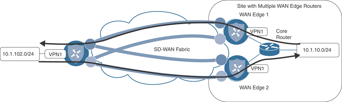
Figure 6-43 Multipathing on the Fabric May Use Multiple WAN Edge Routers for a Single Flow
In order to ensure that both halves of a flow are transiting the same WAN Edge router at a given site, it is common to configure the fabric such that all of the traffic traverses one of the routers in steady state, and the other router is not actively passing traffic until a failure occurs.
Note
There are two different pieces in order to complete this configuration: how traffic is forwarded across the SD-WAN fabric to the WAN Edges, and how traffic is forwarded back from the LAN switches to the WAN Edges. Chapter 5 discussed these separate and distinct policy domains.
This use case is going to focus on manipulating the SD-WAN fabric to prefer a single WAN Edge router when traffic is coming in from the fabric. The corresponding configuration for preferring a single WAN Edge router from the LAN side is discussed in detail in Chapter 9, “Localized Policies.”
As discussed in Chapter 3, the Preference attribute of both TLOCs and OMP routes is evaluated in the OMP best-path selection process. Preference can therefore be altered to manipulate the OMP path selection. Like many things in networking, there is more than one way to accomplish any given objective. To that end, this use case will explore two different methods for manipulating the TLOC Preference values in order to complete this traffic engineering use case. In the following sections, the manipulations at the data centers will be completed with a centralized control policy, and changes at Branch 1 will be made in the WAN Edge configurations locally.
Setting TLOC Preference with Centralized Policy
With the existing policy from Use Case 2, as shown in Example 6-5, both DC1-vEdge1 and DC1-vEdge2 are advertising equal-cost paths to the 10.1.10.0/24 prefix in DC1, as shown in Figure 6-44.
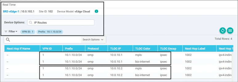
Figure 6-44 Four Paths to 10.1.10.0/24 Transiting Two Different WAN Edge Routers
There are a total of four equal-cost paths for the prefix 10.1.10.0/24: two from DC1-vEdge1 and two from DC1-vEdge2. Each WAN Edge is advertising a path with a color of MPLS and a color of Biz-Internet.
In the previous use cases, we have explored using centralized control policies applied in the outbound direction in order to filter and manipulate routes advertised from vSmart. As the outbound manipulation does not affect the OMP routes and TLOCs in the vSmart’s own tables, they can be more limited in scope, making it easy to apply different changes in the advertisements to different sites. This was seen in the previous use case when the TLOC values for certain OMP routes from the branches were overwritten when advertised to some sites (branches) but not other sites (data centers). Conversely, when the intent is to make a global change to OMP routes or TLOCs, it is often more appropriate to use an inbound centralized control policy. Inbound centralized control policies make manipulations before the vSmart best-path selection algorithm is applied and before the routes are inserted into the vSmart table. The manipulations made by inbound control policies are apparent in the advertisements to all other OMP peers unless overwritten by an additional outbound control policy.
As the intention with this use case is to have all of the routers prefer to send their traffic to vEdge1 over vEdge2 in the data centers, we will use an inbound centralized policy to achieve this global change. The necessary changes to the centralized control policy to achieve this objective are shown in Example 6-7.
Note
Parts of the policy in Example 6-7 that are either irrelevant to this use case or are unchanged from the previous use case are omitted for clarity and brevity. The full text of the centralized policy that implements all of the use cases discussed in this chapter can be found in Example 6-24.
Example 6-7 Use Case 3: Centralized Policy Setting TLOC Preference
policy
 control-policy Hub_and_Spoke_TLOC_Lists
 ! <<<No changes made to this policy from Example 6-5, omitted for brevity>>>
 !
! A new control policy is created to set the TLOC preference values
 control-policy Set_DC_TLOC_Preference
    sequence 1
     match tloc
      originator 10.0.10.1
     !
     action accept
      set
       preference 500
      !
     !
    !
    sequence 11
     match tloc
      originator 10.0.10.2
     !
     action accept
      set
       preference 400
      !
     !
    !
    sequence 21
     match tloc
      originator 10.0.20.1
     !
     action accept
      set
       preference 500
      !
     !
    !
    sequence 31
     match tloc
      originator 10.0.20.2
     !
     action accept
      set
       preference 400
      !
     !
    !
  default-action accept
 !
 lists
 ! <<<No changes made to the lists from Example 6-5, omitted for brevity>>>
 !
!
! The apply-policy statement has been modified to reflect that the new policy
! should be applied inbound on advertisements received from the datacenters
apply-policy
 site-list DCs
  control-policy Set_DC_TLOC_Preference in
 !
 ! The existing policy for the branches remains unchanged
 site-list BranchOffices
  control-policy Hub_and_Spoke_TLOC_Lists out
 !
!
The new policy in Example 6-7 introduces a new control policy to add preference values to the TLOCs that are being advertised from WAN Edge routers in the data centers. In Sequence 1, a new matching criterion is configured: originator. The originator syntax is originator {originator-ip}, where originator-ip is the System IP of the WAN Edge you are looking to match against. In this particular policy example, as the objective is to set different values for WAN Edges at the same site ID, matching with site lists would be ineffective. Once the TLOCs have been matched, the desired preference value is specified in the action statement with the syntax preference {value}. The acceptable range for Preference values is 0 through 4294967295 (232 – 1). In Example 6-7, the Preference values of 500 and 400 are used.
You can see the effect of this policy in Figure 6-45. The output in this figure is an updated display of the same output from Figure 6-44 that was taken after the policy in Example 6-7 has been applied to the SD-WAN network. In this output, only two paths have been installed in the routing table on BR2-vEdge1: the MPLS path and the Biz-Internet path from 10.0.10.1, DC1-vEdge1.

Figure 6-45 Two Paths to 10.1.10.0/24, Both from 10.0.10.1
The output in Figure 6-45 represents the routes that have been installed into the routing table for VPN1 on BR2-vEdge1, but this output is not the complete record of all of the routes that OMP has sent to the WAN Edge. In order to see all of the routes that have been sent from the vSmart, we will use the output of OMP Received Routes from the Real Time tab, as shown in Figure 6-46. This figure shows all of the routes that have been received from OMP peers in a similar fashion to how the outputs of the Cisco IOS command show ip bgp would display all of the routes received from BGP neighbors (even if they are not the best BGP routes or actually installed in the routing table).
Note
In Figure 6-46, in the Search Options field, there is a search for “1.1.1.4,” which is the System IP of vSmart-1. This search has the functional effect of removing all of the duplicate advertisements that would have been received from vSmart-2 (System-IP 1.1.1.5), making it easier for network administrators to understand the table. As the same policy should always be applied to all of the vSmarts, the same route advertisements should come from both vSmarts, and it is safe to filter one set of them from this view.
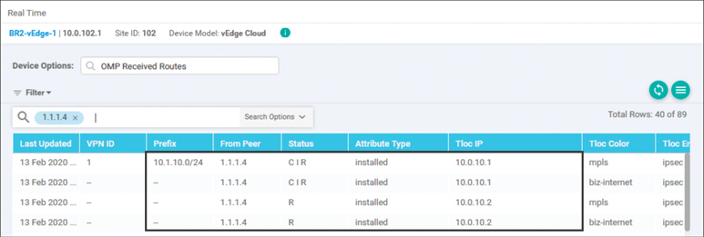
Figure 6-46 OMP Route Table on BR2-vEdge1 Showing Four Paths to 10.1.10.0/24
It is clear from the OMP table that the WAN Edge is still receiving the OMP route advertisements from DC1-vEdge2. These advertisements are the third and fourth entries in the table, with a TLOC IP of 10.0.10.2. The Status column for these routes displays “R,” while the Status column for OMP routes from 10.0.10.1 (the first and second rows) is displayed with a status of “CIR.” Unfortunately, the key for these status codes does not display in the vManage GUI in this version of software, but the key can be found in the output of show omp routes from the CLI, as shown in Example 6-8.
Example 6-8 OMP Status Code Key
BR1-vEdge-1# show omp routes | table
Code:
C   -> chosen
I   -> installed
Red -> redistributed
Rej -> rejected
L   -> looped
R   -> resolved
S   -> stale
Ext -> extranet
Inv -> invalid
Stg -> staged
U   -> TLOC unresolved
<<<omitted for brevity>>>
While the full explanation of these values can be found in the Cisco documentation, a few values are reviewed in Table 6-1.
Table 6-1 OMP Status Codes
Status Code |
Status Meaning |
Explanation |
|---|---|---|
C |
Chosen |
“Chosen” means that this route is the successor of the OMP best-path selection process. |
I |
Installed |
“Installed” means that the OMP route has been installed into the IP routing table. |
R |
Resolved |
“Resolved” means that the TLOC referenced in the OMP route is present and operational. |
As such, the status code of C I R means that the OMP route has been successfully installed in the routing table and is being used for forwarding. The third and fourth OMP routes from 10.0.10.2 have a status code of R. These routes are resolved, but they have not been chosen as the best OMP routes, and they will not be used for forwarding. The reason that these routes have not been chosen can be seen in the output of the OMP TLOCs table, as shown in Figure 6-47.
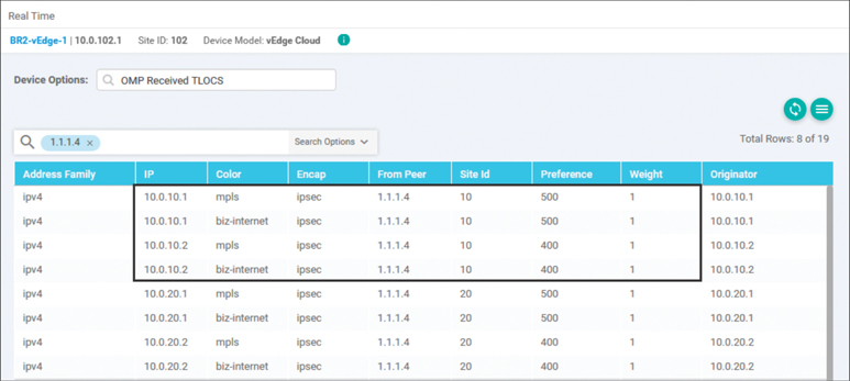
Figure 6-47 OMP TLOC Table on BR2-vEdge2 Showing TLOCs with Different Preference Values
Since the TLOCs from 10.0.10.1 have a higher preference value than the TLOCs from 10.0.10.2, the OMP routes that resolved to the TLOCs from 10.0.10.1 have won the best-path selection process, are “chosen,” and will subsequently be “installed” in the routing table.
The result of this effect is illustrated in Figure 6-48, which shows that the TLOCs from WAN Edge 1 and 2 are received on WAN Edge 3 with two different TLOC Preference values. As the higher Preference value is received for the TLOCs that are advertised from WAN Edge 1, only the tunnels to WAN Edge 1 will be used for forwarding traffic. Should WAN Edge 1 fail, or both TLOCs be removed from WAN Edge 3, WAN Edge 3 would subsequently use the paths being advertised from WAN Edge 2 and the traffic would fail over to the bottom set of tunnels.
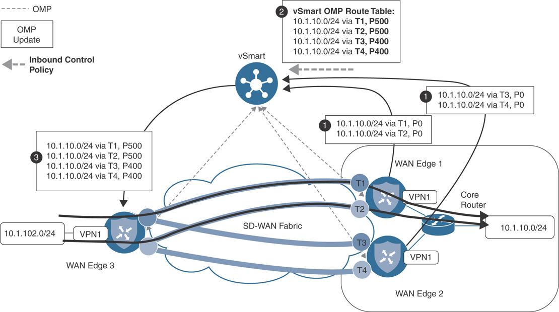
Figure 6-48 Illustration of the Effects of Different Preference Values on the Forwarding Plane
Setting TLOC Preference with Device Templates
The previous example reviewed the purpose of setting the TLOC Preference value and how to set that value using centralized control policies. In addition to using centralized control policies to set the TLOC Preference value, you can also configure it directly on the tunnel interface. Typically, WAN Edge configurations are centrally managed using a combination of feature templates and device templates, as discussed in Chapter 4, “Onboarding and Provisioning.” While Weight and Preference are configurable on the tunnel interfaces with feature templates, they can also be configured with the CLI on the tunnel interface directly with the command encapsulation {ipsec|gre} [preference preference] [weight weight]. Example 6-9 reviews the CLI configuration used to accomplish the same objectives.
Example 6-9 Tunnel Interface Configuration with Weight and Preference
! The following configuration excerpts from BR1-vEdge1 and BR1-vEdge2 that
! indicate the preference and weight settings that have been configured
! on the tunnel interfaces
!
BR1-vEdge-1# BR1-vEdge-1# sho run vpn 0 | include "interface|color|encap"
 interface ge0/0
  tunnel-interface
   encapsulation ipsec preference 50 weight 20
   color biz-internet
 interface ge0/1
  tunnel-interface
   encapsulation ipsec preference 50 weight 5
   color mpls restrict
 interface ge0/2
  tunnel-interface
   encapsulation ipsec preference 5
   color lte
 interface ge0/3
BR1-vEdge-1#

BR1-vEdge-2# sho run vpn 0 | include "interface|color|encap"
 interface ge0/0
  tunnel-interface
   encapsulation ipsec preference 40 weight 20
   color biz-internet
 interface ge0/1
  tunnel-interface
   encapsulation ipsec preference 40 weight 5
   color mpls restrict
 interface ge0/2
  tunnel-interface
   encapsulation ipsec preference 4
   color lte
 interface ge0/4
 interface ge0/5
BR1-vEdge-2#
While the Preference values and their purposes were discussed in depth in the previous section, Example 6-9 also includes the use of the new weight attribute. Weight is used to determine the proportional load-sharing among TLOCs with equal preferences. Weight is not part of the best-path selection algorithm, but instead is used after the best paths are determined to forward proportionally among the paths selected through the best-path process. The weight attribute can range from a value of 1 (default) to 255. Weight is generally configured in proportion to the bandwidths of the links at a single site. In this example, the weight settings of 20 and 5 could represent links with speeds of 20 and 5 Mbps, respectively. Remember, there is no absolute reference value for weight; it is only proportional among the transports at the local site.
In Example 6-9, the preferences on the Biz-Internet, MPLS, and LTE links of BR1-vEdge1 are configured as 50, 50, and 5, respectively. The preferences on BR1-vEdge2 for the Biz-Internet, MPLS, and LTE links are configured as 40, 40, and 4, respectively. The result of this configuration is that, in steady-state operation, where all routers and all links are operational, inbound traffic to Branch 1 will be sent over the Biz-Internet and MPLS links of BR1-vEdge1. These links are configured with the highest preference values and have won the best-path selection process. Furthermore, traffic will be load-shared on a per-flow basis of 20:5, or 4:1, based on the configured weight values. Should the MPLS and Biz-Internet links on BR1-vEdge1 become inoperable, and the TLOCs are no longer resolvable by other routers in the fabric, then the TLOC advertisements from BR1-vEdge2’s MPLS and Biz-Internet links, configured with a TLOC preference of 40, will win the best-path selection process and be used by other routers to send traffic to Branch 1. Only if all MPLS and Biz-Internet TLOCs are unresolvable will the LTE TLOC on BR1-vEdge1 win the best-path selection process with a preference of 5. Lastly, if the LTE TLOC on BR1-vEdge1 is unresolvable, then the last TLOC from Branch 1, the LTE TLOC on BR1-vEdge2 with a preference of 4, will be selected.
You can see the results of these configurations in the TLOCs that have been advertised to DC1-vEdge1, as shown in Figure 6-49.
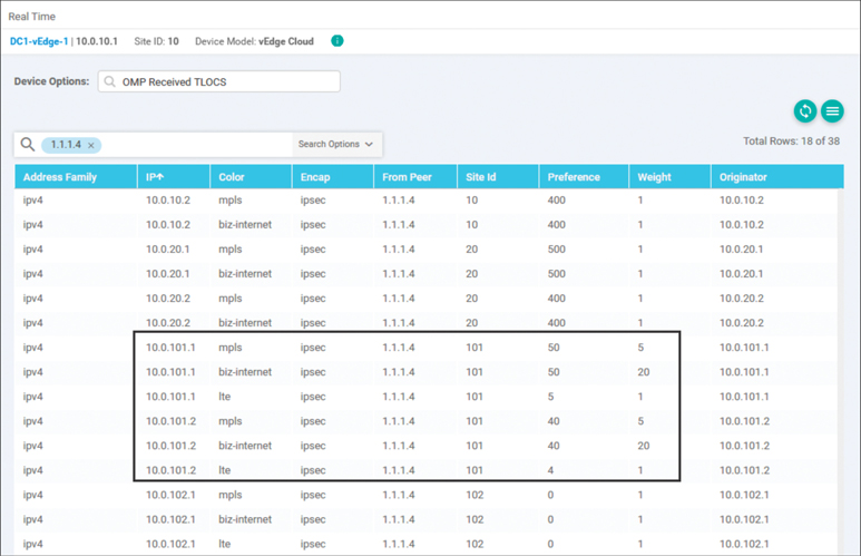
Figure 6-49 Branch 1 TLOCs Are Received in the DC with the Configured Preference and Weight Values
Use Case 3 Review
In this use case, we explored two different mechanisms to configure TLOC Preference values and learned how those Preference values can be used to manipulate how traffic flows across the network. We also used the weight command to be able to perform unequal-cost load-sharing, which is commonly used when network administrators want to use multiple links of different speeds.
Note
Use Case 3 shows two different ways to set the TLOC Preference values. While the ability to write a centralized control policy to override the preferences that are configured on an interface is useful, its primarily utility is for overriding the values that were configured on the tunnel interface, not for configuring the values in the first place. It would be the author’s recommendation to configure the TLOC Preference values on the WAN Edge tunnel interfaces directly, and only manipulate them with centralized control policies when necessary.
Note
Astute readers will have observed that the choices for Preference values for the data center routers were 500 and 400, while the values used for the Branch 1 location were 50, 40, 5, and 4. While the Preference values have no absolute significance, the decision to use values that were an order of magnitude greater for the DCs than the branches was by intention. By configuring the DCs with values of 500 and 400 and the branch with lower values, should a prefix (or a default route) that belongs to a data center ever be inadvertently advertised or redistributed from the branch office, the rest of the WAN Edges in the fabric will still prefer the advertisements from the data centers because of their higher TLOC preference values. This design choice helps to protect the fabric from mistaken or malicious network updates.
Use Case 4: Preferring Regional Data Centers for Internet Access
A common business objective that network administrators need to account for is the desire to have geographically dispersed users access an instance of a shared resource that is closest to the users. For example, if a service is accessible from the data centers in New York and London, the users in Boston should generally use the service in New York, whereas the users in Paris and Berlin should generally use the service in London. The definition of a service can be anything—an enterprise ERP application, a video conferencing server, or (as we will use in this use case) a default route to provide Internet access. Figure 6-50 shows the topology with the configuration objective.
Before we proceed through this use case, it is once more necessary to inject default routes into the VPN1 routing table from the data centers. As with Use Case 2, the specific method used to inject the default routes is inconsequential. With the default routes advertised from the DCs, we can observe that there are four default routes installed in the VPN1 routing table on BR2-vEdge1, as illustrated in Figure 6-51.
The first two of these four routes have TLOC IPs of 10.0.10.1: the System IP of DC1-vEdge1. The third and fourth routes have TLOC IPs of 10.0.20.1, which are advertised from DC2-vEdge1. This implies that, in our example, half of the traffic from our Paris branch will egress at the London data center, and half of the traffic will be inflicted with the additional latency caused by being routed out of the New York data center.
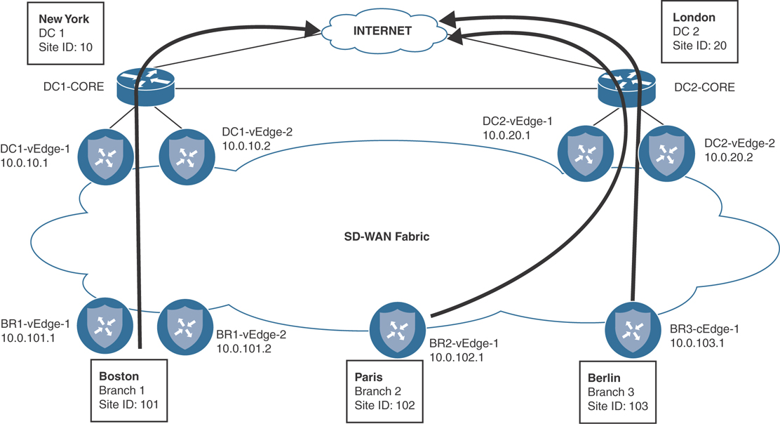
Figure 6-50 Regionalizing Access to a Service, such as Internet Egress
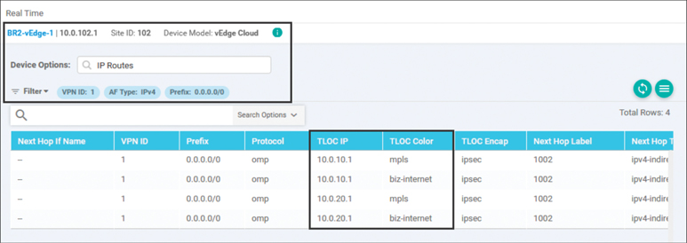
Figure 6-51 BR2-vEdge1 (Paris Branch) Has Installed Four Default Routes in the Routing Table
The same is true for our users in our Boston (Branch 1) and Berlin (Branch 3) branches: half of the traffic will egress locally from the geographically local DC, and half of the traffic will be sent all the way across the Atlantic Ocean. This is confirmed by the Simulate Flows output from the Boston branch, as shown in Figure 6-52.

Figure 6-52 Simulate Flows Output for Destination 0.0.0.0 Confirms That Branch 1 (Boston) Has Four Paths
Note
The Simulate Flows tool can be found in the Troubleshooting section of Monitor > Network > {WAN Edge}. The Simulate Flows tool is able to provide the expected forwarding path of a flow given the current state of the WAN Edge. This output considers the routes in the routing table, the centralized and localized policies that have been applied, and the current performance of the transport links. This can be a very useful tool to see if the policies that have been applied will have the intended effect. The Simulate Flows tool does not actually generate and forward any traffic in the data plane; instead, it indicates the path that would be taken if a flow had existed to be forwarded.
In order to ensure that users always use the Internet egress closest to their geographic location, the centralized control policy in Example 6-10 can be configured on the network. This policy will build on the policies that were configured for the previous use cases and create separate outbound control policies such that the European branches will prefer the default routes from the European data centers. Likewise, the American branches will prefer the default routes from the American data centers.
Example 6-10 Use Case 4: Policy for Regionalizing Internet Access
! The control-policy “Hub_and_Spoke_TLOC_Lists” that was configured in
! Example 6-5 has been changed into two separate centralized
! control policies: Europe_Hub_and_Spoke_TLOC and North_America_Hub_and_Spoke_TLOC.
policy
 control-policy Europe_Hub_and_Spoke_TLOC
    sequence 1
     match tloc
      site-list DCs
     !
     action accept
     !
    !
! A new sequence was added to this policy to match the default route from
! the London DC (combination of prefix-list and site-list as matching criteria),
! and set a preference of 100.
!
    sequence 11
     match route
      prefix-list Default_Route
      site-list Europe_DC
     !
     action accept
      set
       preference 100
      !
     !
    !
    sequence 21
     match route
      site-list DCs
      prefix-list _AnyIpv4PrefixList
     !
     action accept
     !
    !
    sequence 31
     match route
      site-list BranchOffices
      prefix-list _AnyIpv4PrefixList
     !
     action accept
      set
       tloc-list DC_TLOCs
      !
     !
    !
  default-action reject
 !
! Similar to the previous control policy, the following policy matches
! the default route specifically from the New York datacenter and
! sets a preference.  The rest of the policy is unchanged.
!
 control-policy North_America_Hub_and_Spoke_TLOC
    sequence 1
     match tloc
      site-list DCs
     !
     action accept
     !
    !
    sequence 11
     match route
      prefix-list Default_Route
      site-list North_America_DC
     !
     action accept
      set
       preference 100
      !
     !
    !
    sequence 21
     match route
      site-list DCs
      prefix-list _AnyIpv4PrefixList
     !
     action accept
     !
    !
    sequence 31
     match route
      site-list BranchOffices
      prefix-list _AnyIpv4PrefixList     !
     action accept
      set
       tloc-list DC_TLOCs
      !
     !
    !
  default-action reject
 !
 control-policy Set_DC_TLOC_Preference
 ! <<<No changes made to this policy from Example 6-7, omitted for brevity>>>
 !
 lists
  ! <<<Some lists without changes from Example 6-5 are omitted for brevity>>>
  !
  ! A new prefix-list is created to match the default route
  !
  prefix-list Default_Route
   ip-prefix 0.0.0.0/0
  !
  site-list BranchOffices
   site-id 100-199
  !
  site-list DCs
   site-id 10-50
  !
  ! New site lists are created to allow for more specific matching criteria
  ! (Europe_DC and North_America_DC) and more targeted policy application scopes
  ! (Europe_Branches and North_America_Branches) .
  !
  site-list Europe_Branches
   site-id 102-103
  !
  site-list Europe_DC
   site-id 20
  !
  site-list North_America_Branches
   site-id 101
  !
  site-list North_America_DC
   site-id 10
  !
 !
!
! Lastly, the policy that prefers the London DC is applied to the European
! branches, and the policy that prefers the American DC is applied to the
! American Branches.
!
!
apply-policy
 site-list Europe_Branches
  control-policy Europe_Hub_and_Spoke_TLOC out
 !
 site-list North_America_Branches
  control-policy North_America_Hub_and_Spoke_TLOC out
 !
 site-list DCs
  control-policy Set_DC_TLOC_Preference in
 !
!
With this new centralized policy applied to the SD-WAN fabric, the same outputs from the Paris and Boston offices can be evaluated to further understand the policy’s effect. In Figure 6-53, we can see that there are now only two routes installed in the routing table on BR2-vEdge1 (this is in contrast to the four routes present before the policy was applied in Figure 6-51).

Figure 6-53 BR2-vEdge1 (Paris Branch) Has Two Default Routes Installed in the Routing Table
The default routes installed on BR2-vEdge1 (Paris branch) have a TLOC IP address of 10.0.20.1, and they originate from the DC2-vEdge1 router (London data center). Further inspection of the OMP Routes table on BR2-vEdge1 in Figure 6-54 shows that all eight default routes have been received by the WAN Edge, but only these two with a Route Preference of 100 have been selected as the best path and have been inserted into the VPN 1 routing table with a status of C I R.

Figure 6-54 BR2-vEdge1 (Paris Branch) Has Installed Eight Default Routes in the OMP Table
Figure 6-54 shows that BR2-vEdge1 has received all eight default routes (four data center WAN Edge routers, each with MPLS and Biz-Internet TLOCs). Of these eight routes, the four that are being advertised from the London data center (Site ID: 20) have an OMP Route Preference of 100. Of those four, the two that resolve to the 10.0.20.1 TLOC IPs will have a TLOC preference of 500 and will be preferred over the TLOC Preference of 400 for the TLOCs from 10.0.20.2 (from the policy created in Use Case 3). These two preferred routes are being installed into the routing table with a state of “C I R.”
Conversely, the Boston branch has selected two different paths that it will use to forward its traffic toward the Internet, as shown in Figure 6-55.

Figure 6-55 Simulate Flows Output Confirms That Branch 1 (Boston) Will Egress via the New York Data Center (System IP: 10.0.10.1)
The Boston branch (BR1-vEdge1) will use the two paths from DC1-vEdge1 (System-IP: 10.0.10.1) that have both a Route Preference of 100 and a TLOC Preference of 500.
Use Case 4 Review
In this use case, we explored how to solve a common traffic engineering problem, such as choosing the closest instance of a shared resource, that often plagues network administrators. While the configurations reviewed in this section may seem overwhelming for a simple network of just five sites, network administrators should consider that the only configuration that would be necessary to expand this design to a network of 500 or 5,000 sites would be to update the definitions of the Europe_Branches and North_America_Branches site lists. This ability to have a single, centralized place to manage the WAN fabric is a fundamental part of the power of Cisco SD-WAN.
While the examples in the previous use case focused on TLOC Preference, this use case highlighted the OMP Route Preference field, and it demonstrated how these two values can be used together. In the best-path selection algorithm, Route Preference is evaluated before TLOC Preference and, as such, can be used to override the selection that would have been made based on TLOC Preference values for a specific prefix or group of prefixes. This type of flexibility allows network administrators the extremely fine control necessary to solve the business’s traffic engineering objectives.
Use Case 5: Regional Mesh Networks
In Use Case 1, we explored turning the network from the default state of a full mesh topology into a hub-and-spoke network. While a hub-and-spoke design may meet the needs of some organizations, it is often too rigid for many enterprises. Many times, there are legitimate business purposes for some branch office sites to be in communication with other branch office sites. This communication should be permitted without needing to traverse a corporate data center. Sometimes there are sites that share a geographic proximity; other times, organizations may choose to implement these types of policies based on the business function of a site (such as R&D, Manufacturing, Sales, and so on). Figure 6-56 shows altering the existing topology to form a regional mesh of the European offices.
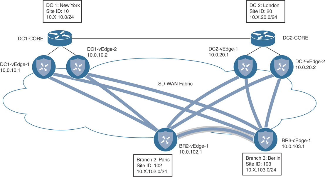
Figure 6-56 Network Topology with Regional Meshes
Building on the policies that were created in the previous use cases, we now need to build regional mesh networks in order to permit the sites in Europe to communicate directly with other sites in Europe without needing to transit a data center to do so. The new data plane tunnel that will need to be created is highlighted in Figure 6-56. Transiting the data centers will still be required in order for a branch office in North America to communicate with a branch office in Europe. A corresponding policy for North America will also be built, but as there is currently only a single branch site in North America, the policy will not have an effect on the network.
Before the new policy is applied, we can see that there is no direct data plane connection between BR2-vEdge1 and BR3-cEdge1 by looking at the real-time BFD Sessions output, as shown in Figure 6-57. All of the BFD sessions terminate at data center WAN Edges, as indicated by the System IPs of 10.0.10.X and 10.0.20.X.

Figure 6-57 BR2-vEdge1 Does Not Currently Have Any Data Plane Tunnels to 10.0.103.1 / Site 103
The traceroute output in Example 6-11 confirms that while Branch 2 has connectivity to Branch 1 and Branch 3, the data plane must currently transit the data center (10.1.10.1), taking a total of two hops to reach both branch offices.
Example 6-11 Tracing the Path from 10.1.102.1 to Other Branches via the Data Center
! Tracing a path from BR2 to BR3 is successful, but the data path is indirect
! and transits a datacenter
!
BR2-vEdge-1# traceroute vpn 1 10.1.103.1
Traceroute  10.1.103.1 in VPN 1
traceroute to 10.1.103.1 (10.1.103.1), 30 hops max, 60 byte packets
 1  10.1.10.1 (10.1.10.1)  5.495 ms  6.579 ms  6.593 ms
 2  10.1.103.1 (10.1.103.1)  13.031 ms * *
BR2-vEdge-1#
!
! Tracing a path from BR2 to BR1 is successful, but the data path is indirect
! and transits a datacenter
!
BR2-vEdge-1# traceroute vpn 1 10.1.101.2
Traceroute  10.1.101.2 in VPN 1
traceroute to 10.1.101.2 (10.1.101.2), 30 hops max, 60 byte packets
 1  10.1.10.1 (10.1.10.1)  53.191 ms  55.226 ms  55.268 ms
 2  10.1.101.2 (10.1.101.2)  76.770 ms  77.283 ms  77.456 ms
BR2-vEdge-1#
In order to enable a regional mesh for the European locations, the policy in Example 6-12 is applied. In order to form regional meshes, the vSmarts will need to advertise the TLOCs and the routes for the other sites within the mesh that connectivity should be established with. For sites that are outside of the regional mesh, the TLOCs will not be advertised, and the OMP routes will be advertised with the data center TLOCs.
Example 6-12 Use Case 5: Policy for Establishing Regional Mesh Data Planes
! In the “Europe_Regional_Mesh” control policy, sequence 11 and sequence 41 were
! added to permit the advertisements of the TLOCs and Routes (respectively) from
! other sites in the Site List “Europe_Branches”.  Additionally, sequence 51 has
! been updated so that only the sites in the “North_America_Branches” site list
! now have their TLOCs updated with the TLOC list.
!
policy
 control-policy Europe_Regional_Mesh
    sequence 1
     match tloc
      site-list DCs

     !
     action accept
     !
    !
    sequence 11
     match tloc
      site-list Europe_Branches
     !
     action accept
     !
    !
    sequence 21
     match route
      prefix-list Default_Route
      site-list Europe_DC
     !
     action accept
      set
       preference 100
      !
     !
    !
    sequence 31
     match route
      site-list DCs
      prefix-list _AnyIpv4PrefixList
     !
     action accept
     !
    !
    sequence 41
     match route
      site-list Europe_Branches
      prefix-list _AnyIpv4PrefixList
     !
     action accept
     !
    !
    sequence 51
     match route
      site-list North_America_Branches
      prefix-list _AnyIpv4PrefixList
     !
     action accept      set
       tloc-list DC_TLOCs
      !
     !
    !
  default-action reject
 !
! Similar to the previous control policy, the following policy permits the TLOCs
! and Routes from the “North_America_Branches” site list to be advertised.
! Additionally, sequence 51 has been updated to only apply to the European
! Branches.
!
control-policy North_America_Regional_Mesh
    sequence 1
     match tloc
      site-list DCs
     !
     action accept
     !
    !
    sequence 11
     match tloc
      site-list North_America_Branches
     !
     action accept
     !
    !
    sequence 21
     match route
      prefix-list Default_Route
      site-list North_America_DC
     !
     action accept
      set
       preference 100
      !
     !
    !
    sequence 31
     match route
      site-list DCs
      prefix-list _AnyIpv4PrefixList
!     action accept
     !
    !
    sequence 41
     match route
      site-list North_America_Branches
      prefix-list _AnyIpv4PrefixList
     !
     action accept
     !
    !
    sequence 51
     match route
      site-list Europe_Branches
      prefix-list _AnyIpv4PrefixList
     !
     action accept
      set
       tloc-list DC_TLOCs
      !
     !
    !
  default-action reject
 !
 control-policy Set_DC_TLOC_Preference
 ! <<<No changes made to this policy from Example 6-7, omitted for brevity>>>
 !
 lists
 ! <<<No changes made to the lists from Example 6-10, omitted for brevity>>>
 !
!
! Lastly, the new policies are applied to the site lists.
!
apply-policy
 site-list Europe_Branches
  control-policy Europe_Regional_Mesh out
 !
 site-list North_America_Branches
  control-policy North_America_Regional_Mesh out
 !
 site-list DCs
  control-policy Set_DC_TLOC_Preference in
!
After the policy in Example 6-12 is applied to the network, the necessary TLOCs are exchanged between BR2-vEdge1 (Paris) and BR3-cEdge1 (Berlin) in order to form data plane tunnels. These five additional tunnels between the two sites can be seen in the BFD Sessions output from BR2-vEdge1, as shown in Figure 6-58.
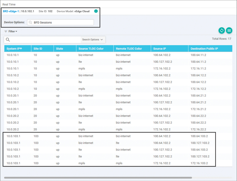
Figure 6-58 BR2-vEdge Has New Data Plane Tunnels to 10.0.103.1 / Site 103
The data plane connectivity can be validated by testing with traceroute, as shown in Example 6-13. The first trace shows there is now a direct path established between Paris and Berlin as part of the European regional mesh. There is no longer a need to transit a data center router to facilitate that connectivity, and the path is now only a single hop. However, as the second traceroute output indicates, there is no direct data plane path from Paris to Boston. Traffic that is going from Branch 2 (Paris) or Branch 3 (Berlin) to Branch 1 (Boston) must still transit the data center.
Example 6-13 Tracing the Path from 10.1.102.1 to Other Branches after the Regional Mesh Is Established
! Tracing a path from BR2 to BR3 is successful and the path is now direct (1 hop)
!
BR2-vEdge-1# traceroute vpn 1 10.1.103.1
Traceroute  10.1.103.1 in VPN 1
traceroute to 10.1.103.1 (10.1.103.1), 30 hops max, 60 byte packets
 1  10.1.103.1 (10.1.103.1)  5.783 ms * *
BR2-vEdge-1#
!
! Tracing a path from BR2 to BR1 is successful, but the data path is still ! ind-
  irect and transits a datacenter (2 hops)
!
BR2-vEdge-1# traceroute vpn 1 10.1.101.2
Traceroute  10.1.101.2 in VPN 1
traceroute to 10.1.101.2 (10.1.101.2), 30 hops max, 60 byte packets
 1  10.1.10.1 (10.1.10.1)  5.307 ms  6.238 ms  18.233 ms
 2  10.1.101.2 (10.1.101.2)  30.879 ms  31.555 ms  31.607 ms
BR2-vEdge-1#
Use Case 5 Review
In this use case, we explored how to alter the structure of the SD-WAN fabric so that it is not purely a hub-and-spoke network, but now consists of multiple, distinct regional mesh networks. Regional meshes can be deployed by network administrators to permit offices that are in close proximity to each other, or offices that serve the same business function, to communicate without the need for a data center to proxy the communication.
This use case also continued to highlight how trivial it is to create increasingly complex topologies through a single, centrally administered control policy. The only thing necessary to turn the hub-and-spoke network into a regional mesh network was to advertise the TLOCs and OMP routes to the sites that we wanted to communicate with each other.
Use Case 6: Enforcing Security Perimeters with Service Insertion
Enterprises often have a need to inject services into the traffic path of the WAN environment. One of the most frequently used services would be a security device such as a firewall. Other potential services would include IPS/IDS, network sniffers, web proxies, caching engines, WAN optimization appliances, and so on. Regardless of the specific type of service, Cisco SD-WAN can natively advertise the availability of the service across the WAN environment and direct traffic flows to that service. For more information on network services, see Chapter 3.
In this use case, there is a need to ensure that users at branch sites in Europe cannot communicate directly with branch sites in North America without first having their traffic inspected by a firewall, and vice versa. We are going to continue to build on the policies created for the previous use cases and modify them to meet this objective.
The first step in service insertion is the configuration of the service itself. For this use case, we are going to provision a firewall attached to DC1-vEdge1 as a network service, as shown in Figure 6-59. Traffic flows that originate at a European branch site, such as the example in the diagram, must be inspected by this firewall before being forwarded to a branch location in North America.
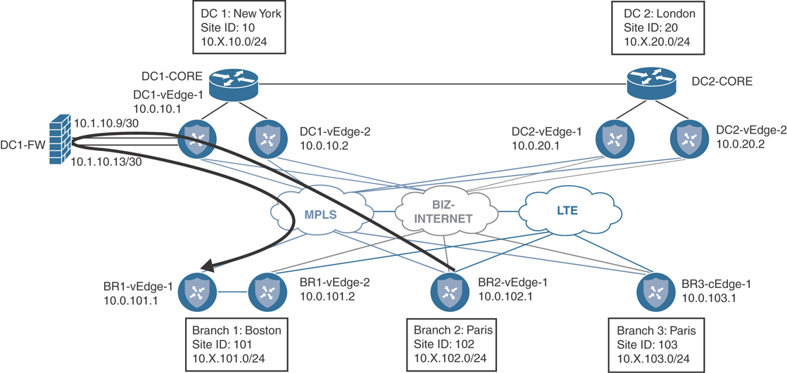
Figure 6-59 Using a Firewall at the Data Center to Inspect Flows Transiting Between Two Branch Sites
Example 6-14 shows the necessary configuration to create the service in DC1-vEdge1 and the advertisements on the vSmart controller as soon as the service is provisioned on the WAN Edge. Once the service has been provisioned, a new label is assigned to indicate which traffic received by this WAN Edge should be forwarded to the service. As Example 6-14 shows, the label in this case is 1005.
Example 6-14 Firewall Service Configuration on DC1-vEdge1
! The minimum configuration necessary for a service is a single line that
! specifies where the service is reachable.
!
DC1-vEdge-1# sho run vpn 1
vpn 1
 service FW address 10.1.10.9
!
!
! As soon as the service is configured, it is advertised to the vSmart and
! ready to be reflected to the entire fabric. Other WAN Edges that want to
! send traffic to this service should use label 1005.
!
DC1-vEdge-1# show omp services family ipv4 service FW | ex >

                                             PATH
VPN    SERVICE  ORIGINATOR  FROM PEER        ID     LABEL    STATUS
-----------------------------------------------------------------------
1      FW       10.0.10.1   0.0.0.0          66     1005     C,Red,R
                            0.0.0.0          68     1005     C,Red,R
A service can either be locally attached or reachable across a GRE tunnel. A locally attached service, such as the firewall in this example, is configured with the syntax service {service-name} address {ip address}, whereas a remotely accessible service would be configured as service {service-name} interface {gre_interface_number1} [gre_interface_number2].
Before the policy is applied to the SD-WAN fabric, Branch 2 is able to reach Branch 1 in two hops, as indicated in Example 6-15. Furthermore, this traffic is being forwarded with a label of 1002, which represents VPN 1.
Example 6-15 Tracing the Path from 10.1.102.1 to Branch 1 Before Service Insertion Is Activated
! Tracing a path from BR2 to BR1 is successful, but the data path transits
! a datacenter.
!
BR2-vEdge-1# traceroute vpn 1 10.1.101.2
Traceroute  10.1.101.2 in VPN 1
traceroute to 10.1.101.2 (10.1.101.2), 30 hops max, 60 byte packets
 1  10.1.10.1 (10.1.10.1)  5.307 ms  6.238 ms  18.233 ms
 2  10.1.101.2 (10.1.101.2)  30.879 ms  31.555 ms  31.607 ms
BR2-vEdge-1#
!
! The OMP Route table indicates that the label that is used to reach
! 10.1.101.0/24 without the service insertion policy is 1002.
!
BR2-vEdge-1# show omp routes 10.1.101.0/24 vpn 1 | nomore

---------------------------------------------------
omp route entries for vpn 1 route 10.1.101.0/24
---------------------------------------------------
            RECEIVED FROM:
peer            1.1.1.4
path-id         232
label           1002
status          C,I,R
loss-reason     not set
lost-to-peer    not set
lost-to-path-id not set
    Attributes:
     originator       10.0.101.1
     type             installed
     tloc             10.0.10.1, mpls, ipsec
<<omitted for brevity>>>
            RECEIVED FROM:
peer            1.1.1.4
path-id         256
label           1002
status          C,I,R
loss-reason     not set
lost-to-peer    not set
lost-to-path-id not set
    Attributes:
     originator       10.0.101.1
     type             installed
     tloc             10.0.10.1, biz-internet, ipsec
<<omitted for brevity>>>
Once the firewall service is configured on the WAN Edge router, only a single line of the centralized control policy needs to be changed in order to direct the branch sites to use the service, as seen in Example 6-16.
Example 6-16 Use Case 6: Service Insertion for Firewalling Branch-to-Branch Transatlantic Traffic
! The only change that has been made is to change the action in sequence
! 51 from referencing the TLOC Lists to now reference the FW service.
!
policy
 control-policy Europe_Regional_Mesh_with_FW
    sequence 1
     match tloc
      site-list DCs
     !
     action accept
     !
    !
   sequence 11
     match tloc
      site-list Europe_Branches
     !
     action accept
     !
    !
    sequence 21
     match route
      prefix-list Default_Route
      site-list Europe_DC
     !
     action accept
      set
       preference 100
      !
     !
    !
    sequence 31
     match route
      site-list DCs
      prefix-list _AnyIpv4PrefixList
     !
     action accept
    !
    !
    sequence 41
     match route
      site-list Europe_Branches
      prefix-list _AnyIpv4PrefixList
     !
     action accept
     !
    !
    sequence 51
     match route
      site-list North_America_Branches
      prefix-list _AnyIpv4PrefixList
     !
     action accept
      set
      service  FW
      !
     !
    !
  default-action reject
 !
 control-policy North_America_Reg_Mesh_with_FW
  ! <<<The change in this policy mirrors the change made in the
  ! Europe_Regional_Mesh_with_FW policy, and was omitted for brevity >>>
 !
 control-policy Set_DC_TLOC_Preference
  ! <<<No changes made to this policy from Example 6-7, omitted for brevity>>>
 !
 lists
 ! <<<No changes made to the lists from Example 6-10, omitted for brevity>>>
 !
 !
!
apply-policy
 site-list Europe_Branches
  control-policy Europe_Regional_Mesh_with_FW out
 !
 site-list North_America_Branches
  control-policy North_America_Reg_Mesh_with_FW out
 !
 site-list DCs
  control-policy Set_DC_TLOC_Preference in
 !
!
Once the service insertion policy has been activated, the OMP Route table is updated to reflect the new label that will be used to forward traffic from BR2-vEdge1 to 10.1.101.0/24. Note that the new label in Example 6-17 is 1005, the same label associated with the firewall service in Example 6-14.
The additional hops in the path from Branch 2 to Branch 1 are caused by the firewall that the policy requires these transatlantic flows to transit. At the same time, flows between Branch 2 and Branch 3, both part of the European mesh, go directly between the WAN Edges and are not required to be filtered through the firewall.
Example 6-17 Tracing the Path from 10.1.102.1 to Branch 1 after Service Insertion Is Activated
! The OMP Route table indicates that the label that is used to reach
! 10.1.101.0/24 without the service insertion policy is 1002.
!
BR2-vEdge-1# show omp routes 10.1.101.0/24 vpn 1 | nomore
---------------------------------------------------
omp route entries for vpn 1 route 10.1.101.0/24
---------------------------------------------------
            RECEIVED FROM:
peer            1.1.1.4
path-id         232
label           1005
status          C,I,R
loss-reason     not set
lost-to-peer    not set
lost-to-path-id not set
    Attributes:
     originator       10.0.101.1
     type             installed
     tloc             10.0.10.1, mpls, ipsec
<<omitted for brevity>>>
            RECEIVED FROM:
peer            1.1.1.4
path-id         256
label           1005
status          C,I,R
loss-reason     not set
lost-to-peer    not set
lost-to-path-id not set
    Attributes:
     originator       10.0.101.1
     type             installed
     tloc             10.0.10.1, biz-internet, ipsec
<<omitted for brevity>>>
!
! Tracing a path from BR2 to BR1 is successful, but the data path now
! has additional hops for the Firewall Service in the datacenter.
!
BR2-vEdge-1# traceroute vpn 1 10.1.101.2
Traceroute  10.1.101.2 in VPN 1
traceroute to 10.1.101.2 (10.1.101.2), 30 hops max, 60 byte packets
 1  10.1.10.1 (10.1.10.1)  6.990 ms  8.770 ms  8.819 ms
 2  10.1.10.9 (10.1.10.9)  8.787 ms  8.824 ms  8.859 ms
 3  10.1.10.14 (10.1.10.14)  8.830 ms  12.380 ms  14.301 ms
 4  10.1.101.2 (10.1.101.2)  23.016 ms  23.874 ms  26.072 ms
BR2-vEdge-1#
!
!
BR2-vEdge-1# traceroute vpn 1 10.1.103.1
Traceroute  10.1.103.1 in VPN 1
traceroute to 10.1.103.1 (10.1.103.1), 30 hops max, 60 byte packets
 1  10.1.103.1 (10.1.103.1)  7.703 ms * *
BR2-vEdge-1#
Use Case 6 Review
In this use case, we reviewed how to provision a network service and manipulate the control policy so that traffic flows were directed to that service. Throughout this example, we used a single firewall that was advertised throughout the fabric. In the real world, it is much more likely that there are redundant sets of network services distributed throughout the WAN fabric. In those cases, the lessons from the previous use cases can be combined with Network Service insertion to ensure that users have reliable, fast access to the services that they need and that the services fail over in a predictable manner.
The traffic engineering that was completed in Use Case 6 was all based on the control plane; the policy was keyed off a specific set of source and destination sites and prefixes. In Chapter 7, “Centralized Data Policies,” we will explore how to continue to enhance this policy so that specific applications can be directed through network services, not just an entire site or subnet.
Use Case 7: Isolating Guest Users from the Corporate WAN
Many organizations have sites where guests are permitted onto the network. Basic security can be provided by confining guest users to their own VPN. However, the default behavior of the SD-WAN fabric is such that connectivity within a single VPN is automatically established between different sites through the exchange of TLOCs and OMP routes. While this automatic behavior is desired for the corporate network segments, most organizations do not want to permit guest users to communicate with other guest users across the WAN fabric. In this use case, we will explore the use of VPN Membership policies in order to prohibit the exchange of control plane information from VPN 3 (the guest user VPN) to the vSmarts.
Before any policy is applied to the network, users in the Guest VPN (VPN 3) are able to reach other guest users at different sites, as shown in Example 6-18.
Example 6-18 Guest VPN Connectivity Between Different Sites
! BR2-vEdge1 is able to reach BR3-cEdge1 in the Guest VPN
!
BR2-vEdge-1# ping vpn 3 10.3.103.1 count 5
Ping in VPN 3
PING 10.3.103.1 (10.3.103.1) 56(84) bytes of data.
64 bytes from 10.3.103.1: icmp_seq=1 ttl=255 time=6.26 ms
64 bytes from 10.3.103.1: icmp_seq=2 ttl=255 time=3.37 ms
64 bytes from 10.3.103.1: icmp_seq=3 ttl=255 time=7.65 ms
64 bytes from 10.3.103.1: icmp_seq=4 ttl=255 time=3.93 ms
64 bytes from 10.3.103.1: icmp_seq=5 ttl=255 time=3.73 ms
In order to prohibit this type of site-to-site connectivity in the Guest VPN, a VPN Membership policy will be added to the centralized control policy. Example 6-19 shows the centralized control policy to implement this change.
Example 6-19 Use Case 7: VPN Membership Policy to Prohibit Guest VPN Connectivity Between Different Sites
! The new piece of this policy is the VPN Membership policy. This VPN membership
! policy permits the VPNs for Corporate (VPN 1), and PCI (VPN 2).  All other
! VPNs will be subject to the default action (reject).
policy
 vpn-membership vpnMembership_-950781881
    sequence 10
     match
      vpn-list CorporateVPN
     !
     action accept
     !
    !
    sequence 20
     match
      vpn-list PCI_VPN
     !
     action accept
     !
    !
  default-action reject
!
 control-policy Set_DC_TLOC_Preference
  ! <<<No changes made to this policy from Example 6-7, omitted for brevity>>>
 !
 control-policy Europe_Regional_Mesh_with_FW
  ! <<<No changes made to this policy from Example 6-16, omitted for brevity>>>
 !
 control-policy North_America_Reg_Mesh_with_FW
  ! <<<No changes made to this policy from Example 6-16, omitted for brevity>>>
 !
 lists
  ! <<<Some lists without changes from Example 6-5 are omitted for brevity>>>
  !
  ! Two new VPN lists were created to work with the VPN membership policy.
  !
  vpn-list CorporateVPN
   vpn 1
  !
  vpn-list PCI_VPN
   vpn 2
  !
 !
!
! Lastly, the VPN Membership policy is applied to the Branch Offices
!
apply-policy
 site-list Europe_Branches
  control-policy Europe_Regional_Mesh_with_FW out
 !
 site-list North_America_Branches
  control-policy North_America_Reg_Mesh_with_FW out
 !
 site-list DCs
  control-policy Set_DC_TLOC_Preference in
 !
 site-list BranchOffices
  vpn-membership vpnMembership_-950781881
 !
!
As Example 6-19 shows, VPN Membership policies follow a similar structure and syntax to the other centralized control policies that we have been working with throughout this chapter. In the most basic sense, the VPN Membership policy specifies which VPNs will be permitted to join the fabric from a specific site. The remaining VPNs are rejected by the default action.
The effect of the VPN Membership policy can clearly be seen by looking at the OMP Services output on the vSmart, as shown in Example 6-20. The command show omp services for VPN 3 lists the service as rejected. In this state, vSmart will not propagate any incoming updates from VPN 3 to other OMP peers, and vSmart will not forward updates about VPN 3 from other WAN Edge routers to these locations that have been rejected. Functionally, this isolates VPN 3 from a control plane perspective. This is proven out in Example 6-20 when users in the guest segment at Branch 2 are no longer able to reach the guest segments at other locations.
Example 6-20 Use Case 7: Effects of VPN Membership Policy
vSmart-1# show omp services family ipv4 vpn 3
C   -> chosen
I   -> installed
Red -> redistributed
Rej -> rejected
L   -> looped
R   -> resolved
S   -> stale
Ext -> extranet
Inv -> invalid
Stg -> staged
U   -> TLOC unresolved
                                             PATH
VPN    SERVICE  ORIGINATOR  FROM PEER        ID     LABEL    STATUS
-----------------------------------------------------------------------
3      VPN      10.0.101.1  10.0.101.1       66     1004     Rej,R,Inv
                            10.0.101.1       68     1004     Rej,R,Inv
                            10.0.101.1       70     1004     Rej,R,Inv
3      VPN      10.0.101.2  10.0.101.2       66     1004     Rej,R,Inv
                            10.0.101.2       68     1004     Rej,R,Inv
                            10.0.101.2       70     1004     Rej,R,Inv
3      VPN      10.0.102.1  10.0.102.1       66     1004     Rej,R,Inv
                            10.0.102.1       68     1004     Rej,R,Inv
                            10.0.102.1       70     1004     Rej,R,Inv
3      VPN      10.0.103.1  10.0.103.1       66     1003     Rej,R,Inv
                            10.0.103.1       68     1003     Rej,R,Inv
                            10.0.103.1       70     1003     Rej,R,Inv
!
!
! BR2-vEdge1 is unable to reach BR3-cEdge1 in the Guest VPN
!
BR2-vEdge-1# ping vpn 3 10.3.103.1 count 5
Ping in VPN 3
PING 10.3.103.1 (10.3.103.1) 56(84) bytes of data.
--- 10.3.103.1 ping statistics ---
5 packets transmitted, 0 received, 100% packet loss, time 3999ms
BR2-vEdge-1#
!
! Guest Users at BR2-vEdge1 are still able to access the public internet via
! local internet egress even though they can no longer reach other branch sites.
!
BR2-vEdge-1# ping vpn 3 8.8.8.8 count 5
Ping in VPN 3
PING 8.8.8.8 (8.8.8.8) 56(84) bytes of data.
64 bytes from 8.8.8.8: icmp_seq=1 ttl=53 time=17.9 ms
64 bytes from 8.8.8.8: icmp_seq=2 ttl=53 time=15.5 ms
64 bytes from 8.8.8.8: icmp_seq=3 ttl=53 time=16.4 ms
64 bytes from 8.8.8.8: icmp_seq=4 ttl=53 time=17.2 ms
64 bytes from 8.8.8.8: icmp_seq=5 ttl=53 time=16.2 ms
--- 8.8.8.8 ping statistics ---
5 packets transmitted, 5 received, 0% packet loss, time 4003ms
rtt min/avg/max/mdev = 15.559/16.704/17.936/0.830 ms
BR2-vEdge-1#
Use Case 7 Review
In this use case, we used a VPN Membership policy to prohibit the Guest VPN from exchanging control plane information with the vSmarts and in turn prohibit the Guest VPN from forwarding traffic across the SD-WAN fabric. While VPN Membership policies can be used to prohibit a VPN from being used at all over the SD-WAN fabric, it can also be used to protect and secure VPNs by prohibiting a WAN Edge that is provisioned either mistakenly or maliciously with a sensitive VPN from being able to exchange control plane information and access the data plane.
Use Case 8: Creating Different Network Topologies per Segment
In this use case, we will continue to revise and combine some of the earlier policies that we have discussed and apply them to different network segments at the same time. Currently, there is a European regional mesh that connects Branch 2 and Branch 3. In this use case, we will keep that forwarding path available for the corporate users in VPN 1, but we will revert the PCI VPN (VPN 2) back to a hub-and-spoke topology.
Before the policy is activated, the output in Example 6-21 confirms that currently both VPN 1 and VPN 2 have direct data plane connections from Branch 2 to Branch 3.
Example 6-21 All VPNs Are Directly Connected Between Branch 2 and Branch 3
!
! BR2-vEdge1 is one hop away from Branch 3 in VPN 1
!
BR2-vEdge-1# traceroute vpn 1 10.1.103.1
Traceroute  10.1.103.1 in VPN 1
traceroute to 10.1.103.1 (10.1.103.1), 30 hops max, 60 byte packets
 1  10.1.103.1 (10.1.103.1)  5.325 ms * *
BR2-vEdge-1#
!
! BR2-vEdge1 is one hop away from Branch 3 in VPN 2
!
BR2-vEdge-1# traceroute vpn 2 10.2.103.1
Traceroute  10.2.103.1 in VPN 2
traceroute to 10.2.103.1 (10.2.103.1), 30 hops max, 60 byte packets
 1  10.2.103.1 (10.2.103.1)  10.646 ms * *
BR2-vEdge-1#
Example 6-22 highlights the necessary changes to the centralized control policy. In order to enact this policy, a new criterion was added to sequence 41 so that it only applies to routes from the corporate VPN. Now sequence 41 will match all routes from European branches in VPN 1 and accept them without any modifications. Additionally, sequence 51 is added to match the routes from European branches in the PCI VPN. These routes have their TLOCs (next-hop attributes) altered so that the prefixes are advertised as being reachable from the European DCs.
Example 6-22 Use Case 8: Multi-Topology Policy
!
! In order to create different logical topologies on a per-VPN basis, the
! routes need to be manipulated on a per-VPN basis.  In this policy, this is
! done in sequence 41, which matches and accepts the routes in the corporate
! VPN, and in sequence 51, which matches routes in the PCI VPN and sets a
! TLOC list with the TLOCs of DC2.
!
policy
 control-policy Euro_Reg_Mesh_with_FW_MultiTopo
    sequence 1
     match tloc
      site-list DCs
     !
     action accept
     !
    !
    sequence 11
     match tloc
      site-list Europe_Branches
     !
     action accept
     !
    !
    sequence 21
     match route
      prefix-list Default_Route
      site-list Europe_DC
     !
     action accept
      set
       preference 100
      !
     !
    !
    sequence 31
     match route
      site-list DCs
      prefix-list _AnyIpv4PrefixList
     !
     action accept
     !
    !
    sequence 41
     match route
      site-list Europe_Branches
     vpn-list CorporateVPN
      prefix-list _AnyIpv4PrefixList
     !
     action accept
     !
    !
    sequence 51
     match route
      site-list Europe_Branches
     vpn-list PCI_VPN
      prefix-list _AnyIpv4PrefixList
     !
     action accept
      set
      tloc-list Europe_DC_TLOCs
      !
     !
    !
    sequence 61
     match route
      site-list North_America_Branches
      prefix-list _AnyIpv4PrefixList
     !
     action accept
      set
       service  FW
      !
     !
    !
  default-action reject
 !
 control-policy North_America_Reg_Mesh_with_FW
  ! <<<No changes made to this policy from Example 6-16, omitted for brevity>>>
 !
 vpn-membership vpnMembership_-950781881
  ! <<<No changes made to this policy from Example 6-19, omitted for brevity>>>
 !
 control-policy Set_DC_TLOC_Preference
  ! <<<No changes made to this policy from Example 6-7, omitted for brevity>>>
 !
 lists
 ! <<<Some lists without changes from Example 6-5 are omitted for brevity>>>
  !
  ! A new TLOC List is created for the TLOCs in DC2
  !
  tloc-list Europe_DC_TLOCs
   tloc 10.0.20.1 color mpls encap ipsec
   tloc 10.0.20.1 color biz-internet encap ipsec
   tloc 10.0.20.2 color mpls encap ipsec
   tloc 10.0.20.2 color biz-internet encap ipsec
  !
 !
!
apply-policy
 site-list Europe_Branches
  control-policy Euro_Reg_Mesh_with_FW_MultiTopo out
 !
 site-list DCs
  control-policy Set_DC_TLOC_Preference in
 !
 site-list North_America_Branches
  control-policy North_America_Reg_Mesh_with_FW out
 !
 site-list BranchOffices
  vpn-membership vpnMembership_-950781881
 !
!
As the multi-topology policy in Example 6-22 shows, creating different logical topologies on a per-VPN basis is a function of manipulating the routes on a per-VPN basis. The centralized policy in this use case created a new TLOC list with the TLOCs from the London data center and applied the TLOC list as the next hop for the routes in VPN 2, the PCI segment. The effect of this policy is that, while the connectivity in VPN 1 will continue to be direct, the communication in VPN 2 will be proxied through the data centers. You can see the effects of this policy in Example 6-23.
Example 6-23 VPN 1 Has a Direct Data Plane; VPN 2 Must Transit the Data Center When Passing Traffic from Branch 2 to Branch 3
!
! BR2-vEdge1 is one hop away from Branch 3 in VPN 1
BR2-vEdge-1# traceroute vpn 1 10.1.103.1
Traceroute  10.1.103.1 in VPN 1
traceroute to 10.1.103.1 (10.1.103.1), 30 hops max, 60 byte packets
 1  10.1.103.1 (10.1.103.1)  13.625 ms * *
BR2-vEdge-1#
!
! BR2-vEdge1 is two hops away from Branch 3 in VPN 2
!
BR2-vEdge-1# traceroute vpn 2 10.2.103.1
Traceroute  10.2.103.1 in VPN 2
traceroute to 10.2.103.1 (10.2.103.1), 30 hops max, 60 byte packets
 1  10.2.20.2 (10.2.20.2)  4.708 ms  6.235 ms  6.263 ms
 2  10.2.103.1 (10.2.103.1)  20.969 ms * *
BR2-vEdge-1#
Use Case 8 Review
In this use case, we created a multi-topology policy by combining the elements that were previously used in prior use cases. This use case demonstrates how network administrators can create different data plane topologies on a per-segment basis to meet their business needs by using the VPN criterion in addition to other criteria to select, filter, and manipulate the control plane updates.
Use Case 9: Creating Extranets and Access to Shared Services
In the final centralized control policy use case, we will explore building an extranet. Extranets are commonly used by enterprises to provide multiple business partners with access to a shared resource, such as an ERP solution, while at the same time ensuring that the partners cannot directly access each other. In our lab, we are going to use VPNs 101 and 102, at Sites 101 and 102, respectively, to represent the business partners. The shared resource that these partners need to access will be in VPN 100 at DC1. Figure 6-60 depicts the extranet that will be built on top of the existing policies from the previous examples.

Figure 6-60 Building an Extranet to Enable Partner Connectivity
In order to build the necessary connectivity to accomplish this design, there are several key parts of the centralized policy that will need to be either adjusted or created from scratch. The VPN Membership policy created in Use Case 7 will need to be adjusted to account for the new VPNs being used for the extranet. Next, the inbound route policies will need to be either edited (in the case of the data centers) or created (in the case of the branches) so that the route leaking via the export-to command can take effect. The Set_DC_TLOC_Preference policy has to be rewritten to include the statements for route leaking. As there can only be a single control policy for a specific site ID applied in a single direction, the functions of setting the TLOC preferences and leaking the routes from VPN 100 to VPN 101 and 102 need to be combined into a single policy. This new policy has been renamed “DC_Inbound_Control_Policy” to reflect a broader purpose than just manipulating the DC TLOCs.
The policy in Example 6-24 implements the necessary changes to completely deploy this extranet. As this is the last set of examples for Chapter 6, the policy is presented in its entirety so that it can be used as a reference.
Example 6-24 Use Case 9: Extranet
policy
!
! The VPN membership policy is extended to account for the additional VPNs
! that need to be advertised to form the extranet connectivity.  Specifically,
! these are grouped into the CLIENT_VPNS (VPNs 101 and 102), and the
! SERVICE_VPN (VPN 100).
!
 vpn-membership vpnMembership_-1376283532
    sequence 10
     match
      vpn-list CLIENT_VPNS
     !
     action accept
     !
    !
    sequence 20
     match
      vpn-list CorporateVPN
     !
     action accept
     !
    !
    sequence 30
     match
      vpn-list SERVICE_VPN
     !
     action accept
     !
    !
    sequence 40
     match
      vpn-list PCI_VPN
     !
     action accept
     !
    !
  default-action reject
 !
!
! The former “Set_DC_TLOC_Preference” policy has been renamed to
! “DC_Inbound_Control_Policy” and has had sequence 41 inserted in order to perform
! the route leaking from VPN 100 to VPN 101 and 102.
!
 control-policy DC_Inbound_Control_Policy
    sequence 1
     match tloc
      originator 10.0.10.1
     !
     action accept
      set
       preference 500
      !
     !
    !
    sequence 11
     match tloc
      originator 10.0.10.2
     !
     action accept
      set
       preference 400
      !
     !
    !
    sequence 21
     match tloc
      originator 10.0.20.1
     !
     action accept
      set
       preference 500
      !
     !
    !
    sequence 31
     match tloc
      originator 10.0.20.2
     !
     action accept
      set
       preference 400
      !
     !
    !
    sequence 41
    match route
     vpn-list SERVICE_VPN
      prefix-list _AnyIpv4PrefixList
     !
    action accept
     export-to vpn-list CLIENT_VPNS
      set
      !
      ! An OMP TAG is similar to a route tag that can be found in other
      ! routing protocols.  While it is not strictly necessary to set an OMP TAG
      ! during redistribution, it may become useful in the future to assist with
      ! tracking how routes are propagating as well as creating additional
      ! criteria to filter on.
      !
       omp-tag 100
      !
     !
    !
  default-action accept
 !
!
! The “North_America_Reg_Mesh_with_FW” policy remains unchanged from previous
! versions.
!
 control-policy North_America_Reg_Mesh_with_FW
    sequence 1
     match tloc
      site-list DCs
     !
     action accept
     !
    !
    sequence 11
     match tloc
      site-list North_America_Branches
     !
     action accept
     !
    !
    sequence 21
     match route
      prefix-list Default_Route
      site-list North_America_DC
     !
     action accept
      set
       preference 100
      !
     !
    !
    sequence 31
     match route
      site-list DCs
      prefix-list _AnyIpv4PrefixList
     !
     action accept
     !
    !
    sequence 41
     match route
      site-list North_America_Branches
      prefix-list _AnyIpv4PrefixList
     !
     action accept
     !
    !
    sequence 51
     match route
      site-list Europe_Branches
      prefix-list _AnyIpv4PrefixList
     !
     action accept
      set
       service  FW
      !
     !
    !
  default-action reject
 !
 !
 ! The “Euro_Reg_Mesh_with_FW_MultiTopo” policy remains unchanged from previous
 ! versions.
 !
 control-policy Euro_Reg_Mesh_with_FW_MultiTopo
    sequence 1
     match tloc
      site-list DCs
     !
     action accept
     !
    !
    sequence 11
     match tloc
      site-list Europe_Branches
     !
     action accept
     !
    !
    sequence 21
     match route
      prefix-list Default_Route
      site-list Europe_DC
     !
     action accept
      set
       preference 100
      !
     !
    !
    sequence 31
     match route
      site-list DCs
      prefix-list _AnyIpv4PrefixList
     !
     action accept
     !
    !
    sequence 41
     match route
      site-list Europe_Branches
      vpn-list CorporateVPN
      prefix-list _AnyIpv4PrefixList
     !
     action accept
     !
    !
    sequence 51
     match route
      site-list Europe_Branches
      vpn-list PCI_VPN
      prefix-list _AnyIpv4PrefixList
     !
     action accept
      set
       tloc-list Europe_DC_TLOCs
      !
     !
    !
    sequence 61
     match route
      site-list North_America_Branches
      prefix-list _AnyIpv4PrefixList
     !
     action accept
      set
       service  FW
      !
     !
    !
  default-action reject
 !
 !
 ! A new control policy is created in order to be applied inbound from the
 ! branch sites and export the routes from VPN 101 and VPN 102 to VPN 100.
 ! An OMP tag is again added during the route leaking, and while not strictly
 ! required, it is highly recommended to do so.
 !
 control-policy Branch_Extranet_Route_Leaking
    sequence 1
     match route
      vpn 101
      prefix-list _AnyIpv4PrefixList
     !
     action accept
      export-to vpn-list SERVICE_VPN
      set
       omp-tag 101
      !
     !
    !
    sequence 11
     match route
      vpn 102
      prefix-list _AnyIpv4PrefixList
     !
     action accept
      export-to vpn-list SERVICE_VPN
      set
       omp-tag 102
      !
     !
    !
  default-action accept
 !
 lists
  prefix-list Default_Route
   ip-prefix 0.0.0.0/0
  !
  site-list BranchOffices
   site-id 100-199
  !
  site-list DCs
   site-id 10-50
  !
  site-list Europe_Branches
   site-id 102-103
  !
  site-list Europe_DC
   site-id 20
  !
  site-list North_America_Branches
   site-id 101
  !
  site-list North_America_DC
   site-id 10
!
  tloc-list Europe_DC_TLOCs
   tloc 10.0.20.1 color mpls encap ipsec
   tloc 10.0.20.1 color biz-internet encap ipsec
   tloc 10.0.20.2 color mpls encap ipsec
   tloc 10.0.20.2 color biz-internet encap ipsec
  !
  vpn-list CLIENT_VPNS
   vpn 101
   vpn 102
  !
  vpn-list CorporateVPN
   vpn 1
  !
  vpn-list PCI_VPN
   vpn 2
  !
  vpn-list SERVICE_VPN
   vpn 100
  !
  prefix-list _AnyIpv4PrefixList
   ip-prefix 0.0.0.0/0 le 32
  !
 !
!
!
 ! Lastly, all of the policies are applied.  Note, the policies that perform
 ! route leaking must be applied inbound.
 !
apply-policy
 site-list Europe_Branches
  control-policy Euro_Reg_Mesh_with_FW_MultiTopo out
 !
 site-list DCs
  control-policy DC_Inbound_Control_Policy in
 !
 site-list BranchOffices
  control-policy Branch_Extranet_Route_Leaking in
  vpn-membership vpnMembership_-1376283532
 !
 site-list North_America_Branches
  control-policy North_America_Reg_Mesh_with_FW out
 !
!
In Example 6-24, route leaking is configured in both the Branch_Extranet_Route_Leaking and the DC_Inbound_Control_Policy policies with the export-to action. The export-to action allows the matching routes to be copied from the existing VPN and injected into a different VPN or VPN list using the syntax export-to {vpn vpn-id | vpn-list vpn-list}.
Route leaking is a powerful and flexible tool that network administrators have at their disposal. However, there are some limitations with how the export-to command must be used as of software version 19.2. First, the export-to action must be applied on an inbound control policy. If the export-to action is applied in the outbound direction, the action will have no effect. Second, the export-to command only works to leak routes from a service-side VPN into a different service-side VPN. The export-to command cannot be used to leak routes into or out of VPN 0 or VPN 512. The isolation of these VPNs is intentional and, specifically with VPN 0, has significant security implications. As such, there is no native mechanism using policies to leak routes into or out of these special VPNs. There is some discussion in Chapter 12, “Cisco SD-WAN Design and Migration,” about different design concepts that look to solve these challenges.
When the policy in Example 6-24 is applied, the results of the route leaking can be seen in the routing tables on BR1-vEdge1 and BR2-vEdge1, as shown in Figure 6-61 and Figure 6-62, respectively. The BR1-vEdge1 and BR2-vEdge1 routing tables have installed the two routes for the Services VPN. These routes are also displayed with a Tag of 100 as a reminder that they originated in VPN 100.

Figure 6-61 Service Routes from VPN 100 Have Been Imported into VPN 101

Figure 6-62 Service Routes from VPN 100 Have Been Imported into VPN 102
Lastly, the data plane of the extranet can be validated by ensuring that VPN 101 and VPN 102 both have access to the shared services hosted in VPN 100, but that VPN 101 cannot communicate directly with VPN 102. Example 6-25 shows the results from the pings to test the data plane of the extranet.
Example 6-25 Validating the Data Plane Connectivity of the Extranet Connections
!
! BR2-vEdge1 is able to reach the shared services in VPN 100
!
BR2-vEdge-1#
BR2-vEdge-1# ping 10.100.10.1 vpn 102 count 5
Ping in VPN 102
PING 10.100.10.1 (10.100.10.1) 56(84) bytes of data.
64 bytes from 10.100.10.1: icmp_seq=1 ttl=64 time=3.98 ms
64 bytes from 10.100.10.1: icmp_seq=2 ttl=64 time=2.49 ms
64 bytes from 10.100.10.1: icmp_seq=3 ttl=64 time=3.34 ms
64 bytes from 10.100.10.1: icmp_seq=4 ttl=64 time=2.02 ms
64 bytes from 10.100.10.1: icmp_seq=5 ttl=64 time=2.09 ms
--- 10.100.10.1 ping statistics ---
5 packets transmitted, 5 received, 0% packet loss, time 4003ms
rtt min/avg/max/mdev = 2.024/2.787/3.981/0.760 ms
!
! BR2-vEdge1 is not able to directly reach hosts in VPN 101
!
BR2-vEdge-1# ping 10.101.101.1 vpn 102 count 5
Ping in VPN 102
PING 10.101.101.1 (10.101.101.1) 56(84) bytes of data.
From 127.1.0.2 icmp_seq=1 Destination Net Unreachable
From 127.1.0.2 icmp_seq=2 Destination Net Unreachable
From 127.1.0.2 icmp_seq=3 Destination Net Unreachable
From 127.1.0.2 icmp_seq=4 Destination Net Unreachable
From 127.1.0.2 icmp_seq=5 Destination Net Unreachable
--- 10.101.101.1 ping statistics ---
5 packets transmitted, 0 received, +5 errors, 100% packet loss, time 3999ms
!
!
! BR1-vEdge1 is able to reach the shared services in VPN 100
!
BR1-vEdge-1# ping 10.100.10.1 vpn 101 count 5
Ping in VPN 101
PING 10.100.10.1 (10.100.10.1) 56(84) bytes of data.
64 bytes from 10.100.10.1: icmp_seq=1 ttl=64 time=3.45 ms
64 bytes from 10.100.10.1: icmp_seq=2 ttl=64 time=2.81 ms
64 bytes from 10.100.10.1: icmp_seq=3 ttl=64 time=2.78 ms
64 bytes from 10.100.10.1: icmp_seq=4 ttl=64 time=2.70 ms
64 bytes from 10.100.10.1: icmp_seq=5 ttl=64 time=2.90 ms
--- 10.100.10.1 ping statistics ---
5 packets transmitted, 5 received, 0% packet loss, time 4005ms
rtt min/avg/max/mdev = 2.705/2.931/3.450/0.275 ms
!
! BR1-vEdge1 is not able to directly reach hosts in VPN 102
!
BR1-vEdge-1# ping 10.102.102.1 vpn 101 count 5
Ping in VPN 101
PING 10.102.102.1 (10.102.102.1) 56(84) bytes of data.
From 127.1.0.2 icmp_seq=1 Destination Net Unreachable
From 127.1.0.2 icmp_seq=2 Destination Net Unreachable
From 127.1.0.2 icmp_seq=3 Destination Net Unreachable
From 127.1.0.2 icmp_seq=4 Destination Net Unreachable
From 127.1.0.2 icmp_seq=5 Destination Net Unreachable
--- 10.102.102.1 ping statistics ---
5 packets transmitted, 0 received, +5 errors, 100% packet loss, time 3999ms
BR2-vEdge-1#
The output in Example 6-25 confirms that the extranet is working as expected. VPNs 101 and 102 have access to the shared resource that exists in VPN 100, but VPN 101 and 102 are not able to communicate between themselves.
Use Case 9 Review
In this use case, an extranet was created to allow business partners to communicate while still maintaining security and isolation across the SD-WAN fabric. This extranet was configured by establishing a unique VPN for each of the different entities, then leaking routes from the client VPNs (101 and 102) into the Service VPN (100), and vice versa. Route leaking with centralized control policies is a technique that can be used for many different purposes. In addition to creating extranets for shared services access, as was done in this use case, another common use case that requires VPN leaking is using the SD-WAN Security feature set, particularly the Zone-Based Firewall. Cisco SD-WAN Security will be discussed further in Chapter 10, “Cisco SD-WAN Security.”
Summary
This chapter discussed one of the key types of SD-WAN policies: centralized control policies. Several different use cases using centralized control policies were reviewed, including how policies can be used to manipulate the structure of the SD-WAN data plane fabric, turning an SD-WAN fabric from a full-mesh deployment to a strict hub-and-spoke deployment or a regional mesh. In addition, many different types of traffic engineering use cases were also reviewed, including using TLOC lists to manipulate the next-hop information of an OMP route, as well as network service insertion. Finally, using centralized control policies to harden the security posture of the network was discussed, including using VPN Membership policies and building extranets with route leaking. This chapter illustrated how these different kinds of policies can be combined and used together to create the architecture necessary to meet any business objective.
Review All Key Topics
Review the most important topics in the chapter, noted with the Key Topic icon in the outer margin of the page. Table 6-2 lists these key topics and the page numbers on which each is found.
Table 6-2 Key Topics
Key Topic Element |
Description |
Page |
|---|---|---|
Paragraph |
Data plane tunnels are built from the TLOCs advertisements that a WAN Edge receives from the vSmarts. |
137 |
Paragraph |
The status of the BFD session is indicative of the status of the data plane tunnel. |
138 |
Paragraph |
The TLOC attribute in OMP routes functions as the next-hop address, and by changing the TLOC attribute, it is possible to redirect traffic flows. |
152 |
Paragraph, Example 6-8 |
OMP Route Status codes display the current status of the route, and only routes with a status of C I R are going to be used to forward traffic. |
175 |
OMP Status Codes |
175 |
|
Paragraph, Figure 6-48 |
When multiple routes to the same prefix via different TLOCs exist, if all of the other route attributes are equivalent, only the routes with the greatest TLOC Preference value will be used. |
176 |
Paragraph |
The Weight attribute is used to configure unequal-cost load-sharing. |
178 |
Figure 6-54, Paragraph |
When multiple routes with different OMP preferences exist, only the routes with the greatest Preference values will be used. |
187 |
Paragraph |
VPN Membership policies can prohibit the acceptance of OMP updates about a specific VPN by the vSmarts, and they stop the vSmarts from forwarding updates about the prohibited VPNs to the WAN Edges. |
204 |
Paragraph |
Route leaking can only be performed in control policies applied in the inbound direction. |
220 |
Define Key Terms
Define the following key terms from this chapter and check your answers in the glossary:
Chapter Review Questions
1. What is the default setting of the default action in a centralized control policy?
Accept
Permit
Reject
Deny
There is no default action; one must be configured manually.
2. Which of the following are configuration options for a TLOC list?
Site ID
System IP
Color
Encapsulation
Preference
Weight
VPN
Prefix
3. The TLOC attribute “Weight” is used for which of the following?
The first and most important criterion in the OMP best-path selection process
The final tie-breaker in the OMP best-path selection process
Determining the ratio of flows for load-sharing on the TLOCs that have been selected as the best paths
Turning off the anti-gravity machine
4. OMP Route Preference values can be configured via feature templates and device templates.
True
False
5. What is the status of an OMP process that has been inserted into the IP Routing table?
C I R
C R
R
Rej, R, Inv
6. “Preference” is an OMP attribute associated with which of the following?
TLOCs
OMP routes
Both TLOCs and OMP routes
Neither TLOCs nor OMP routes
7. What are VPN Membership policies used to do?
Determine which users belong to which VPNs.
Determine which routes belong to which VPNs.
Determine which WAN Edges belong to which SD-WAN fabrics.
Determine which VPNs will be permitted to join the overlay fabric on a WAN Edge router.
Determine the ratio of flows for load-sharing on the TLOCs that have been selected as the best paths.
8. Centralized control policies that leak routes must always be applied in the outbound direction.
True
False
9. A centralized control policy can be used to leak routes between service-side VPNs and VPN 0.
True
False
10. Which type of policy is used to export OMP routes from one VPN to another VPN?
Route Import/Export policies
VPN Membership policies
Centralized control policies
Localized control policies
No policy; it is not possible to have the same route in more than one VPN.
Reference
Cisco SD-WAN Command Line Reference, https://www.cisco.com/c/en/us/td/docs/routers/sdwan/command/sdwan-cr-book.html