
Chapter 9. Localized Policies
This chapter covers the following topics:
Introduction to Localized Policies: This section covers the different types of localized policies and how these policies relate to other types of policies used by the Cisco SD-WAN solution.
Localized Control Policies: This section covers localized control policies and how they can be used to manipulate routing advertisements to routers outside of the SD-WAN fabric.
Localized Data Policies: This section covers the construction and use of localized data policies and particularly access control lists.
Quality of Service Policies: This section covers the construction and application of quality of service with localized policies, including traffic classification, queuing and scheduling, and congestion management.
As discussed in Chapter 5, “Introduction to Cisco SD-WAN Policies,” two main types of policies are used in the Cisco SD-WAN solution: centralized policies and localized policies. Chapters 6–8 focused on the different types of centralized policies; this chapter will discuss localized policies. Just as there are two main classifications of centralized policies (centralized control policies and centralized data policies), there are also localized control policies and localized data policies. This chapter reviews these different types of localized policies, how they are configured and applied, and common use cases for different types of localized policies.
Introduction to Localized Policies
The two main types of localized policies are localized control policies and localized data policies. Just as centralized control policies are used to manipulate the control plane and routing advertisements inside of the Cisco SD-WAN fabric, localized control policies are used to manipulate routing advertisements that happen at the perimeter of the SD-WAN fabric, when the WAN Edge router is communicating with other routers via BGP, OSPF, or EIGRP. Localized control policies can be used to filter routes or manipulate routing attributes such as OSPF cost, BGP local-preference, and EIGRP delay. Localized data policies are used to manipulate individual packets or flows transiting the data plane of the WAN Edge router. There are two main types of localized data policies: access control lists (ACLs) and quality of service (QoS). ACLs can be used to filter, rewrite, or apply additional services to a packet or flow as it transits the router. QoS is used for marking, queuing, and scheduling in order to allow network administrators to prioritize certain classes of traffic. While centralized policies and localized policies share many similarities in their structure, since centralized policies are activated on the vSmart and localized policies are applied as part of the WAN Edge configuration templates, there are no common configuration elements or lists that can be shared between the two different types of policies. Figure 9-1 illustrates the relationships between these different types of policies.
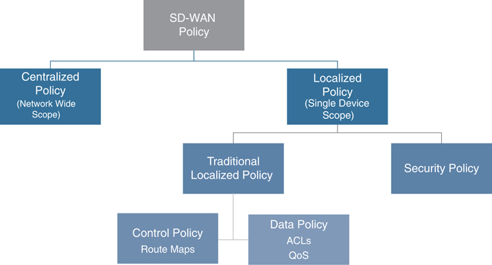
Figure 9-1 Localized Policy Overview
In addition to localized control policies and localized data policies, there is a special type of localized policy called a security policy. Security policies will be discussed in detail in Chapter 10, “Cisco SD-WAN Security.”
Localized Control Policies
The purpose of localized control policies is to manipulate route attributes or filter out routes completely as they are advertised from the WAN Edge routers into the rest of the routing domain via traditional routing protocols. One of the reasons to do this is to be able to differentially prefer one WAN Edge router over another at a site that is configured with dual routers for high availability. While the Cisco SD-WAN solution deploys an active/active high-availability design, and there is no concept of a “standby” router (each router is always capable of forwarding any received traffic at all times during operation), there are some advantages to deploying a network in such a way that ensures that particular flows always transit particular routers.
This design construct was discussed in great detail in Use Case 3 in Chapter 6, “Centralized Control Policies.” While Chapter 6 covered the necessary traffic engineering steps to accomplish this on the WAN side of the router using TLOC preferences, the following example shows how to complete this design using different routing policies on the LAN side of the WAN Edge routers.
Figure 9-2 shows a detailed topology of Data Center 1. We can see, in this example, that there are two WAN Edge routers that connect to a traditional core switch. With default configuration, the core switch will load-share traffic across both WAN Edge routers.

Figure 9-2 Data Center Topology
In order to prefer one WAN Edge router and create the desired symmetric flow patterns, we will be adjusting the routing advertisements from DC1-vEdge-1 and DC1-vEdge-2 so that the routes being advertised from the DC1-vEdge-1 are more preferred. Therefore, traffic flowing from the data center across the WAN will prefer DC1-vEdge-1 in steady-state operation. In this case, as the network is using eBGP as the routing protocol between the WAN Edge routers and the data center core, we will be manipulating route preferences with BGP attributes. While different attributes could be used, such as AS Path Prepending, in this example we will use MED, or the Multi-Exit Discriminator (also called Metric). Since lower MED values are always preferred, we will set the MED value on the routes advertised from DC1-vEdge-1 to 100 and on the DC1-vEdge-2 to 1000.
Before any policy is applied, we can see that DC1-Core has equal-cost paths from each of the WAN Edge routers, indicated by the two next hops for each route (10.1.10.1 and 10.1.10.5). With this default state, the DC1-Core would use ECMP to load-share flows between the two routers, as shown in Example 9-1.
Example 9-1 DC1-Core Routing Table
DC1-CORE#sho ip route bgp
Codes: L - local, C - connected, S - static, R - RIP, M - mobile, B - BGP
       D - EIGRP, EX - EIGRP external, O - OSPF, IA - OSPF inter area
       N1 - OSPF NSSA external type 1, N2 - OSPF NSSA external type 2
       E1 - OSPF external type 1, E2 - OSPF external type 2
       i - IS-IS, su - IS-IS summary, L1 - IS-IS level-1, L2 - IS-IS level-2
       ia - IS-IS inter area, * - candidate default, U - per-user static route
       o - ODR, P - periodic downloaded static route, H - NHRP, l - LISP
       a - application route
       + - replicated route, % - next hop override, p - overrides from PfR
Gateway of last resort is 192.168.255.1 to network 0.0.0.0
      10.0.0.0/8 is variably subnetted, 11 subnets, 3 masks
B        10.1.20.0/30 [20/1000] via 10.1.10.5, 00:01:49
                      [20/1000] via 10.1.10.1, 00:01:49
B        10.1.20.4/30 [20/1000] via 10.1.10.5, 00:01:49
                      [20/1000] via 10.1.10.1, 00:01:49
B        10.1.101.0/24 [20/1000] via 10.1.10.5, 00:01:49
                       [20/1000] via 10.1.10.1, 00:01:49
B        10.1.102.0/30 [20/1000] via 10.1.10.5, 00:01:49
                       [20/1000] via 10.1.10.1, 00:01:49
B        10.1.103.0/24 [20/1000] via 10.1.10.5, 00:01:49
                       [20/1000] via 10.1.10.1, 00:01:49
DC1-CORE#
The process of building a localized control policy is similar to the process of building centralized policies covered in the previous chapters. However, the process of applying that policy is slightly different. In this first example, we will work through the process of configuring the policy in the vManage GUI; for all other examples in this chapter, we will simply review the CLI configuration.
The first step in the configuration process is to create the route policies themselves. The route policies that are used for configuring localized control policies are similar in structure to the centralized control policies reviewed in Chapter 6. For this particular example, we will be creating two different route policies: one that sets a MED value of 100, and the second that sets a MED value of 1000. These route policies can be configured in vManage from the Configuration > Policies menu, followed by selecting Route Policy from the Custom Options menu in the upper corner, as shown in Figure 9-3.

Figure 9-3 Accessing the Route Policy Configurations
Select the Create New option under the Add Route Policy menu, as shown in Figure 9-4.

Figure 9-4 Creating a New Route Policy
The route policy will need to be configured with a name and description. The next step is to add a new sequence type by clicking the + Sequence Type button on the left, as shown in Figure 9-5. In a localized control policy, the only applicable sequence type is a route sequence, so this button will automatically add a new route sequence, as highlighted on the left. In the new route sequence, add a new sequence rule by clicking + New Sequence Rule. As this MED value will apply to all of the routes being advertised by the WAN Edge, there will be no matching criteria specified. In order to have all of the routes permitted by this first sequence rule, click the Actions tab and click the Accept radio button. From the list of available actions, select the Metric action and then specify the MED value of 100. Finally, select Save Match and Actions under the individual sequence and then select Save Route Policy at the very bottom of the page to complete the configuration of the route policy.
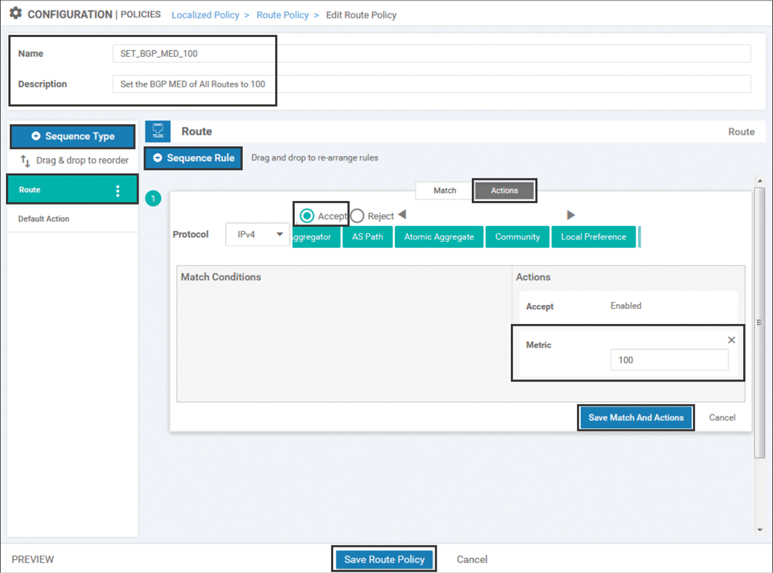
Figure 9-5 Configuring a Route Policy to Set the BGP MED Value to 100
The CLI rendering of the policy can also be seen by clicking the Preview button in the lower-left corner. Example 9-2 shows the CLI display for this policy.
Example 9-2 Route Policy to Set the BGP MED Value
  route-policy SET_BGP_MED_100
    sequence 1
     action accept
      set
       metric 100
      !
     !
    !
  default-action reject
!
Note
The default-action step in this policy has no effect, as all of the routes are matched in sequence 1. Ordinarily, network administrators will need to pay special care to the default-action statements in route-policy configurations.
A second route policy is then created for the second WAN Edge router in order to set the MED to 1000 by repeating all of the steps to create the first policy. Figure 9-6 illustrates that policy.

Figure 9-6 Configuring a Route Policy to Set the BGP MED Value
Once the route policies have been created, a localized policy will need to be created. As with centralized policies, where a single centralized policy could contain many different component parts, a similar structure is true of localized policies. There is a single localized policy that is applied to any router, but that localized policy can include multiple localized control policies and multiple localized data policies that are applied to different parts of the local router’s configuration. In order to create the local policy, select the Add Policy option from the local policy screen to start the Local Policy Wizard, as shown in Figure 9-7.

Figure 9-7 Creating a New Localized Policy with the New Policy Wizard
Click Next in the first several steps of the Local Policy Wizard until you arrive at the Configure Route Policy option. On this screen, import the two route policies that were previously created and attach them to this localized policy by clicking on the +Add Route Policy button and then selecting the policies, as shown in Figure 9-8 and Figure 9-9.

Figure 9-8 Import Existing Route Policies into the Local Policy Wizard
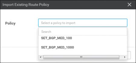
Figure 9-9 Select the Route Policies to Be Imported into the Localized Policy
Finally, the local policy will need to have a name and description configured, as shown in Figure 9-10, and then it can be saved by clicking the Save Policy button at the bottom of the screen.

Figure 9-10 Saving the Localized Policy
The first step in utilizing the localized policy that was created is to attach it to the device template. This is accomplished by editing the specific device template and then selecting the local policy to be applied from the drop-down in the Additional Templates section, as shown in Figure 9-11.
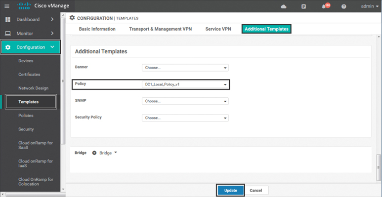
Figure 9-11 Adding the Local Policy to the Device Template
Once the local policy has been added to the device template, selecting the Update option will immediately push a configuration change to all of the devices that are attached to this device template. If more than one device is attached to the device template, users will receive a warning that they are changing multiple devices.
One of the greatest differences between centralized policies and localized policies is where the policies are applied. Centralized policies are applied to the vSmart’s configurations; localized policies are applied as part of each individual WAN Edge router’s configuration.
Once the local policy has been created and applied to the device template, it then needs to be applied to the feature template where it will ultimately be used. Similar to a Cisco IOS router, the process of creating a route map does not in and of itself configure the router to utilize the created route map. The route policy will still have to be referenced in the configuration in order to have any effect. This can be seen by examining the configuration of the WAN Edge router from the CLI, as shown in Example 9-3, where the route policies are in the running configuration but are not referenced by the BGP configuration. They, therefore, will not have any effect.
Example 9-3 Viewing the Route Policies in the Device Configuration
! Route-Policies are visible in the configuration of the WAN Edge router.
!
DC1-vEdge-1# show running-config policy
policy
 route-policy SET_BGP_MED_100
  sequence 1
   action accept
    set
     metric 100
    !
   !
  !
  default-action reject
 !
 route-policy SET_BGP_MED_1000
  sequence 1
   action accept
    set
     metric 1000
    !
   !
  !
  default-action reject
 !
!
! The route polices are not yet applied to any routing protocol.
DC1-vEdge-1# sho run vpn 1
vpn 1
 router
  bgp 65500
   propagate-aspath
   address-family ipv4-unicast
    redistribute omp
   !
   neighbor 10.1.10.2
    no shutdown
    remote-as 10
    address-family ipv4-unicast
    ! <<<No Route Policy Applied Here>>>
    !
   !
  !
!
 interface ge0/2
  ip address 10.1.10.1/30
  no shutdown
 !
!
DC1-vEdge-1#
!
! The only reference to the name of the policy is in the policy definition.
! The policy is not currently applied anywhere in the configuration.
DC1-vEdge-1# show run | include _BGP_
 route-policy SET_BGP_MED_100
 route-policy SET_BGP_MED_1000
DC1-vEdge-1#
Note
From an order of operations perspective, the localized policy must be tied to the device template before the individual component policies can be referenced anywhere else in the device configuration. This may be a counterintuitive process for engineers who are unfamiliar with it. If the opposite were done—that is, if the route maps were referenced by the BGP configuration before the localized policy was attached to the device template—then vManage would display a syntax error indicating that a route map was referenced but was not found in the localized policy configuration. Therefore, it is important to always update the localized policy tied to the device template prior to referencing any component parts of that localized policy.
Once the localized policy has been successfully attached to the device template, we can then go back and update the BGP feature template so that the configured BGP neighbors will utilize the new route map. In order to configure this, the Address Family radio button will need to be set to On and then the Address Family combo box will need to be set to ipv4-unicast. Under the address family, the Route Policy Out radio button will need to be checked and then a variable created for the name of the policy, as shown in Figure 9-12.

Figure 9-12 Adding the Local Policy to the Device Template
By creating a variable for the name of the route policies, we can use the same configuration across both routers and reference the two different route maps that we have created and configured with the local policy. This structure allows for maximum template reuse. Once this configuration is saved, we will be prompted to provide the names of the route policies. We will be using SET_BGP_MED_100 for DC1-vEdge-1 and SET_BGP_MED_1000 for DC1-vEdge-2.
Once the changes are applied, this configuration can be seen by looking at the CLI configuration for the BGP protocol in VPN 1 on both of the DC WAN Edge routers, as shown in Example 9-4.
Example 9-4 Viewing the Route Policies Applied in the Device Configuration
! Each WAN Edge router is applying a different route-policy.
!
DC1-vEdge-1# sho run vpn 1
vpn 1
 router
  bgp 65500
   propagate-aspath
   address-family ipv4-unicast
    redistribute omp
   !
   neighbor 10.1.10.2
    no shutdown
    remote-as 10
    address-family ipv4-unicast
     route-policy SET_BGP_MED_100 out
!
   !
  !
 !
 interface ge0/2
  ip address 10.1.10.1/30
  no shutdown
 !
!
DC1-vEdge-1#
DC1-vEdge-2# sho run vpn 1
vpn 1
 router
  bgp 65500
   propagate-aspath
   address-family ipv4-unicast
    redistribute omp
   !
   neighbor 10.1.10.6
    no shutdown
    remote-as 10
    address-family ipv4-unicast
     route-policy SET_BGP_MED_1000 out
    !
   !
  !
 !
 interface ge0/2
  ip address 10.1.10.5/30
  no shutdown
 !
!
DC1-vEdge-2#
After applying the configuration in Example 9-4, we can now return to the DC core router in Example 9-5 and see that the router still receives both sets of BGP advertisements: one from DC1-vEdge-1 and one from DC1-vEdge-2. However, only the routing advertisements from DC1-vEdge-1 are selected as best paths, and only the routes from DC1-vEdge-1 are inserted into the routing table. In this way, we can be assured that the core switch will send all traffic to the DC1-vEdge-1 router in steady state.
Example 9-5 Viewing the Effects of the Route Policies on Neighboring Routers
!
! Routes from both WAN Edge routers are present in the BGP table, but the different
! MED (metric) values influence the BGP path selection algorithm to select only the
! routes from DC1-vEdge-1.
!
DC1-CORE#sho ip bgp
BGP table version is 16, local router ID is 192.168.255.8
Status codes: s suppressed, d damped, h history, * valid, > best, i - internal,
              r RIB-failure, S Stale, m multipath, b backup-path, f RT-Filter,
              x best-external, a additional-path, c RIB-compressed,
              t secondary path, L long-lived-stale,
Origin codes: i - IGP, e - EGP, ? - incomplete
RPKI validation codes: V valid, I invalid, N Not found

     Network          Next Hop            Metric LocPrf Weight Path
 *    10.1.20.0/30     10.1.10.5             1000             0 65500 ?
 *>                    10.1.10.1              100             0 65500 ?
 *    10.1.20.4/30     10.1.10.5             1000             0 65500 ?
 *>                    10.1.10.1              100             0 65500 ?
 *    10.1.101.0/24    10.1.10.5             1000             0 65500 ?
 *>                    10.1.10.1              100             0 65500 ?
 *    10.1.102.0/30    10.1.10.5             1000             0 65500 ?
 *>                    10.1.10.1              100             0 65500 ?
 *    10.1.103.0/24    10.1.10.5             1000             0 65500 ?
 *>                    10.1.10.1              100             0 65500 ?
!
! The routing table on the DC1-Core router now only lists routes from DC1-vEdge-1.
! This is indicated by the next hop address of 10.1.10.1.
!
DC1-CORE#sho ip route bgp
Codes: L - local, C - connected, S - static, R - RIP, M - mobile, B - BGP
       D - EIGRP, EX - EIGRP external, O - OSPF, IA - OSPF inter area
       N1 - OSPF NSSA external type 1, N2 - OSPF NSSA external type 2
       E1 - OSPF external type 1, E2 - OSPF external type 2
       i - IS-IS, su - IS-IS summary, L1 - IS-IS level-1, L2 - IS-IS level-2
       ia - IS-IS inter area, * - candidate default, U - per-user static route
       o - ODR, P - periodic downloaded static route, H - NHRP, l - LISP
       a - application route
       + - replicated route, % - next hop override, p - overrides from PfR
Gateway of last resort is 192.168.255.1 to network 0.0.0.0
      10.0.0.0/8 is variably subnetted, 11 subnets, 3 masks
B        10.1.20.0/30 [20/100] via 10.1.10.1, 00:03:08
BGP table version is 16, local router ID is 192.168.255.8
B        10.1.20.4/30 [20/100] via 10.1.10.1, 00:03:08
B        10.1.101.0/24 [20/100] via 10.1.10.1, 00:03:08
B        10.1.102.0/30 [20/100] via 10.1.10.1, 00:03:08
B        10.1.103.0/24 [20/100] via 10.1.10.1, 00:03:08
DC1-CORE#
As Example 9-5 shows, localized control policies can be used to manipulate the routing advertisements into or out of the WAN Edges in order to perform traffic engineering at the local site. Administrators should recall that the configuration explained in this section is only half of the configuration necessary to get all of the traffic at a site to flow through a particular WAN Edge. This configuration handles how routers attached to the service VPNs will forward traffic to the WAN Edge. In order to manipulate how other SD-WAN routers will forward traffic to this site across the SD-WAN fabric, see Use Case 3 in Chapter 6.
Localized Data Policies
The second main use of localized policies is to configure data policies (specifically access control lists) used for filtering or remarking traffic at the interface level. In this section, we will continue to expand on the previously configured local policy and add an interface ACL to prohibit SSH sessions through the service-side interface. Before any policy is configured, we can observe that it is possible to connect into the DC1-vEdge-1 router from DC1-Core with the SSH protocol, as shown in Example 9-6.
Example 9-6 Establishing an SSH Session from DC1-Core to DC1-vEdge-1
! DC1-Core is able to successfully establish an SSH session to DC1-vEdge-1.
!
DC1-CORE#ssh -l admin 10.1.10.1
viptela 19.2.0
Password:
Last login: Mon Nov 11 10:42:08 2019 from 1.1.1.6
Welcome to Viptela CLI
admin connected from 10.1.10.2 using ssh on DC1-vEdge-1
DC1-vEdge-1#
In order to filter this data plane traffic with a local policy, a new access control list (ACL) will need to be configured from the Custom Options menu, as shown in Figure 9-13.

Figure 9-13 Creating a New Access Control List
The objective of dropping SSH traffic can be achieved by matching on a source port of 22 or a destination port of 22 and dropping the traffic, as shown in Figure 9-14. In order to test that the policy is working, we are also configuring a counter on the ACL sequence. Finally, remember when configuring a policy to drop selected traffic like this, it is necessary to change the default action to accept in order to permit any other traffic to be forwarded.
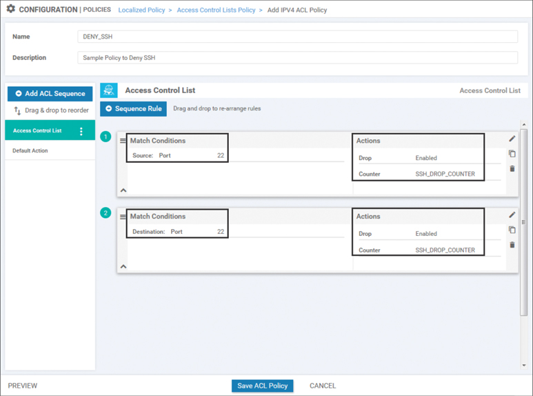
Figure 9-14 Configuring an ACL to Drop Traffic on Port 22
This new ACL can then be added into the previously configured local policy by editing the localized policy we created previously and importing this ACL into it, as has been done with other policy examples throughout the book. Example 9-7 shows the full localized policy.
Example 9-7 Previewing the Localized Policy with Route Policies and ACLs
policy
! New ACL “DENY_SSH” added
 access-list DENY_SSH
    sequence 1
     match
      source-port 22
     !
     action drop
      count SSH_DROP_COUNTER
     !
    !
    sequence 11
     match
      destination-port 22
     !
     action drop
      count SSH_DROP_COUNTER
     !
    !
  default-action accept
 !
! Existing route-policies are still contained in the localized policy
 route-policy SET_BGP_MED_1000
    sequence 1
     action accept
      set
       metric 1000
      !
     !
    !
  default-action reject
 !
 route-policy SET_BGP_MED_100
    sequence 1
     action accept
      set
      metric 100
      !
     !
    !
  default-action reject
 !
 !
!
Just as there can only be a single centralized vSmart policy that is activated at any point in time (although that policy can have many different component parts), the same is true of localized policies. Each router can only have a single localized policy attached to it at any given point in time and that single localized policy can have as many component route policies and/or ACLs as necessary.
Note
Because this policy is currently in use by one or more routers, saving changes to the localized policy will result in configuration changes to all of the routers that currently reference this policy. If you would prefer to configure a change to the local policy but to apply that change at a later point in time, this can be achieved by copying the current localized policy and then editing the copy of that policy. When you are ready to apply the necessary changes at some point in the future, this can be achieved by changing which localized policy (LocalizedPolicy_v1 to LocalizedPolicy_v2) is applied in the device template.
Now that the ACL has been configured as part of the localized policy, the last step is to reference the ACL as part of the interface configuration template. This can be achieved by setting the Ingress ACL – IPv4 option on the interface template to On and then specifying the name of the ACL in the IPv4 Ingress Access List field, as shown in Figure 9-15.

Figure 9-15 Configuring the Interface Template to Reference the ACL in the Localized Policy
The effect of this policy can be seen by attempting to establish an SSH session again from the DC Core to the WAN Edge router, as shown in Example 9-8. It is clear from the example that the SSH session no longer opens correctly. Additionally, the ACL counter is incrementing on DC1-vEdge-1 to reflect that the packets are being matched and dropped by the ACL.
Example 9-8 Effects of Applying an Access Control List
! The DC1-CORE router is no longer able to SSH into DC1-vEdge-1.
DC1-CORE#ssh -l admin 10.1.10.1
% Destination unreachable; gateway or host down
DC1-CORE#

! DC1-vEdge-1 shows the blocked packets in the ACL counter
DC1-vEdge-1# show policy access-list-counters
NAME      COUNTER NAME      PACKETS  BYTES
--------------------------------------------
DENY_SSH  SSH_DROP_COUNTER  1        58
As this example shows, interface ACLs are useful for filtering traffic flows transiting the router. ACLs can also be used for a number of other actions, including mirroring traffic to an additional destination, manipulating the forwarding path by setting an alternative next-hop address, policing the data rate of a type of traffic, and remarking the traffic by setting a different DSCP value. While these use cases are beyond the scope covered in this book, additional information on these topics can be found in the Cisco documentation.
Note
Tunnel interfaces have implicit ACLs applied to them that automatically restrict the types of traffic permitted to enter these interfaces. Applying an explicit ACL can override this default behavior. Further information about the behavior when explicit ACLs are configured on tunnel interfaces can be found in the Cisco SD-WAN documentation.
Quality of Service Policies
Quality of service (QoS) is also configured with localized policies. As discussed in Chapters 7 and 8, centralized data and App-Route policies can be used to make forwarding decisions in the Cisco SD-WAN fabric. While those two technologies are used to determine which path a specific packet or flow should take, the QoS configuration in the localized data policy is used to perform scheduling and queuing functions. QoS is often used by network administrators to minimize delay and jitter for business-critical applications such as VoIP and video conferencing, and it’s used to prioritize the queuing and forwarding of specific traffic classes. It can also be used to manage buffer allocation across different types of traffic, as well as to determine the congestion management behavior when the buffers are full. A detailed discussion of the generic quality of service theory and each of these features is beyond the scope of this book, but there are additional resources available in the Cisco documentation and through Cisco Press. This chapter focuses on the command structure necessary to implement QoS with Cisco SD-WAN.
Note
Quality of service configurations are highly dependent on the functionalities supported by the underlying hardware platforms. The following section will deal with features that are common across all hardware platforms. These configuration examples are derived from the vEdge-Cloud virtual routing platform. Additional features may be available depending on the specific code version and hardware platform.
When utilizing QoS functionalities on the vEdge-Cloud—or related platforms such as the vEdge-5000, ISR-1100-4G, ISR-1100-4GLTE, and the ISR-1100-6G—the commands cloud-qos and cloud-qos-service-side must be configured in the local policy. These commands can be seen in Example 9-14 at the end of this section.
Although it may be overwhelming at first glance, configuring a QoS policy on a WAN Edge router is a simple process that consists of the following steps:
Step 1. Assign traffic to forwarding classes
Step 2. Map forwarding classes to hardware queues
Step 3. Configure the scheduling parameters for each queue
Step 4. Map all of the schedulers together into a single QoS map
Step 5. Configure the interface with the QoS map
In the following sections, we will configure each of these steps in turn to observe the entire process of building a QoS policy. The sample policy we will build will have different classes of traffic: a class for voice and video traffic that is placed in the priority queue, a class for business-critical traffic, and a class for everything else.
Step 1: Assign Traffic to Forwarding Classes
The first step in the QoS process is to assign traffic flows to different forwarding classes. This step can be performed with either a centralized data policy or with an ACL from a localized data policy by specifying the class action. In this section, we will continue to expand on the existing localized policy we created in Example 9-7. Additional sequences will be added in order to classify traffic into the appropriate forwarding classes, as shown in Example 9-9.
Example 9-9 Expanding ACL to Perform QoS Classification
policy
<<< omitted for brevity>>>
 access-list DENY_SSH
 !
 ! Sequences 1 and 11 are the existing Sequences to Block SSH traffic
 !
    sequence 1
     match
      source-port 22
!
     action drop
      count SSH_DROP_COUNTER
     !
    !
    sequence 11
     match
      destination-port 22
     !
     action drop
      count SSH_DROP_COUNTER
     !
    !
 !
 ! Sequences 21, 31, and 41 match permitted traffic and set the ‘class’ action
 ! to specify the forwarding class.
    sequence 21
     match
      dscp 40 46
     !
     action accept
      class VOICE_AND_VIDEO
     !
    !
    sequence 31
     match
      source-data-prefix-list CRITICAL_SERVERS
     !
     action accept
      class CRITICAL_DATA
     !
    !
    sequence 41
     action accept
      class BEST_EFFORT
     !
    !
  default-action accept
 !
 lists
  data-prefix-list CRITICAL_SERVERS
   ip-prefix 10.250.1.0/24
  !
 !
!
As shown in Example 9-9, three user-defined forwarding classes have been created:
VOICE_AND_VIDEO
CRITICAL_DATA
BEST_EFFORT
Traffic is matched into the VOICE_AND_VIDEO class based on the DSCP markings of the traffic. In Cisco SD-WAN policies, DSCP is always specified in decimal values. Traffic is matched into the CRITICAL_DATA class by matching the data prefix list CRITICAL_SERVERS. Any traffic that is not matched into either the VOICE_AND_VIDEO or CRITICAL_DATA class will be placed into the BEST_EFFORT class. While this example matches on DSCP values and IP addresses, any criteria that can be matched in an ACL or a centralized data policy can be used to match traffic and set the class action.
Step 2: Map Forwarding Classes to Hardware Queues
The next step in the forwarding process is to assign the forwarding classes to their hardware queues. This configuration is accomplished in the GUI by creating a new type of localized policy list, the class map. The class map configuration references the name of the classes that were configured in Step 1 and the specific hardware queue that this traffic will be forwarded through. Example 9-10 shows the class map configuration for the forwarding classes created in Step 1.
Example 9-10 Class Map Configuration
  class-map
   class BEST_EFFORT queue 7
   class CRITICAL_DATA queue 1
   class VOICE_AND_VIDEO queue 0
  !
In this example, the VOICE_AND_VIDEO class is mapped to queue 0, the CRITICAL_DATA traffic is mapped to queue 1, and the BEST_EFFORT traffic is mapped to queue 7.
Step 3: Configure the Scheduling Parameters for Each Queue
The next step in the process is to configure the scheduling parameters for each individual queue. Each scheduler will contain a reference to the traffic class, the maximum bandwidth to be used during congestion, the percentage of the buffer that is allocated, the scheduling mechanism (Low Latency Queuing or Weighted Round Robin), and the congestion management technique (tail drop or random early detection). Example 9-11 provides a sample configuration of these features. Note that as of software version 19.2, Cisco SD-WAN only supports the configuration of a single scheduler per queue. When QoS configurations are generated in the vManage GUI, additional classes called Queue0, Queue1, Queue2, and so on are created and the schedulers are tied to these classes. The examples in this section were manually configured to avoid this extra complexity.
Example 9-11 QoS Scheduler Configuration
  !
  qos-scheduler VOICE_AND_VIDEO_SCHED
   class VOICE_AND_VIDEO
   bandwidth-percent 20
   buffer-percent 20
   scheduling llq
   drops tail-drop
  !
  qos-scheduler CRITICAL_DATA_SCHED
   class CRITICAL_DATA
   bandwidth-percent 30
   buffer-percent 40
   scheduling wrr
   drops red-drop
  !
  qos-scheduler BEST_EFFORT_SCHED
   class BEST_EFFORT
   bandwidth-percent 50
   buffer-percent 40
   scheduling wrr
   drops red-drop
  !
Currently (as of version 19.2), the Cisco WAN Edge routers support a total of eight queues, numbered 0 through 7. Queue 0 is always configured as a low-latency queue and is the only queue that supports Low Latency Queuing. Additionally, all control traffic that is originated by the WAN Edge router, including DTLS/TLS, BFD probes, and routing protocol traffic, is automatically mapped to queue 0. Any user-defined traffic classes that are mapped to queue 0, such as the VOICE_AND_VIDEO class from Example 9-10, must also be configured for Low Latency Queuing. Queues 1 through 7 support Weighted Round Robin forwarding, where the weighting is proportional to the configured bandwidth percent.
Step 4: Map All of the Schedulers Together into a Single QoS Map
The final configuration step in the localized policy for a QoS configuration is to tie all of the schedulers together with a single QoS map that can be referenced under the interface configuration. Example 9-12 demonstrates a sample QoS map configuration.
Example 9-12 QoS Map Configuration
!
  qos-map MY_QOS_MAP
   qos-scheduler VOICE_AND_VIDEO_SCHED
   qos-scheduler CRITICAL_DATA_SCHED
   qos-scheduler BEST_EFFORT_SCHED
!
Step 5: Configure the Interface with the QoS Map
The last part of the process is to configure the interface to use the QoS map that was created in the previous step. This step is analogous to configuring a “service-policy” in traditional Cisco IOS configuration. QoS maps can be applied to any interface to affect the scheduling and queuing of outbound traffic. However, since the available WAN bandwidth is typically lower than LAN bandwidth and, therefore, congestion is most likely to occur on the WAN, QoS maps are most commonly configured on the transport (WAN) interfaces. Example 9-13 demonstrates how to add the QoS map to the transport interfaces.
Example 9-13 Applying QoS Maps to Transport Interfaces
!
! QoS Maps applied to transport interfaces in VPN 0.
!
DC1-vEdge-1# sho run vpn 0
vpn 0
 interface ge0/0
  ip address 100.64.11.2/30
  tunnel-interface
   <<<omitted for brevity>>>
  !
  no shutdown

qos-map  MY_QOS_MAP
 !
 interface ge0/1
  ip address 172.16.11.2/30
  tunnel-interface
   <<<omitted for brevity>>>
  !
  no shutdown

qos-map  MY_QOS_MAP
!
!
!
! Sample show commands to validate that the QOS Map is applied
! to the correct interfaces.
!
DC1-vEdge-1# show policy qos-map-info

QOS MAP     INTERFACE
NAME        NAME
-----------------------
MY_QOS_MAP  ge0/0
            ge0/1
!
!
! Sample show commands to validate that the QOS Map is configured
! with the correct QoS Schedulers.
!
DC1-vEdge-1# show policy qos-scheduler-info

                       BANDWIDTH  BUFFER          QOS MAP
QOS SCHEDULER NAME     PERCENT    PERCENT  QUEUE  NAME
--------------------------------------------------------------
BEST_EFFORT_SCHED      50         40       7      MY_QOS_MAP
CRITICAL_DATA_SCHED    30         40       1      MY_QOS_MAP
VOICE_AND_VIDEO_SCHED  20         20       0      MY_QOS_MAP
The entirety of the localized policy containing QoS configuration is provided as a reference in Example 9-14. In this example, we can see the ACL used to assign the traffic to forwarding classes (Step 1) and that the forwarding classes are mapped to hardware queues (Step 2), the scheduling parameters are configured in the QoS schedulers (Step 3), and the schedulers are mapped together into a single QoS map that can be referenced under an interface (Step 4).
Example 9-14 Complete QoS Configuration
DC1-vEdge-1# show running-config policy
policy
 !
 ! ‘cloud-qos’ and ‘cloud-qos-service-side’ commands are necessary on
 ! vEdge-Cloud based platforms
 !
 cloud-qos
 cloud-qos-service-side
 lists
  data-prefix-list CRITICAL_SERVERS
  ip-prefix 10.250.1.0/24
  !
 !
 route-policy SET_BGP_MED_100
  <<<omitted for brevity>>>
 !
 route-policy SET_BGP_MED_1000
  <<<omitted for brevity>>>
!
! Step 2: Class maps are used to map the forwarding classes to hardware queues
!
 class-map
  class VOICE_AND_VIDEO queue 0
  class CRITICAL_DATA queue 1
  class BEST_EFFORT queue 7
 !
 !
 ! Step 1:  Access Lists are used to assign the traffic to forwarding classes
 !
 access-list DENY_SSH
   <<<omitted for brevity>>>
  !
  sequence 21
   match
    dscp 40 46
   !
   action accept
    class VOICE_AND_VIDEO
   !
  !
  sequence 31
   match
    source-data-prefix-list CRITICAL_SERVERS
   !
   action accept
    class CRITICAL_DATA
   !
  !
  sequence 41
   action accept
    class BEST_EFFORT
   !
  !
  default-action accept
 ! !
 Step 3: QoS Schedulers are used to configure the forwarding
 ! parameters of each traffic class.
 !
 !
 qos-scheduler BEST_EFFORT_SCHED
  class             BEST_EFFORT
  bandwidth-percent 50
  buffer-percent    40
  drops             red-drop
 !
 qos-scheduler CRITICAL_DATA_SCHED
  class             CRITICAL_DATA
  bandwidth-percent 30
  buffer-percent    40
  drops             red-drop
 !
 qos-scheduler VOICE_AND_VIDEO_SCHED
  class             VOICE_AND_VIDEO
  bandwidth-percent 20
  buffer-percent    20
  scheduling        llq
 !
 ! Step 4: Map all of the QoS Schedulers together with a QoS Map
 !
 qos-map MY_QOS_MAP
  qos-scheduler BEST_EFFORT_SCHED
  qos-scheduler CRITICAL_DATA_SCHED
  qos-scheduler VOICE_AND_VIDEO_SCHED
 !
!
Summary
This chapter reviewed localized policies and how they are used with the Cisco SD-WAN solution. There are two main types of localized policies: localized control policies and localized data policies. Both of these types of localized policies are configured in a single policy section of the WAN Edge router configuration and are device specific in scope. This chapter reviewed examples of how localized control policies are used to manipulate routing advertisements outside of the SD-WAN fabric and how this functionality can be used to achieve certain traffic engineering and outcomes. Localized data policies can be used to create access control lists and manipulate traffic flowing in the data plane through the router. Localized data policies can also be used to configure quality of service on the WAN Edge routers, including queuing and congestion management, in order to prioritize certain classes of traffic over others.
Review All Key Topics
Review the most important topics in the chapter, noted with the Key Topic icon in the outer margin of the page. Table 9-1 lists these key topics and the page numbers on which each is found.
Table 9-1 Key Topics
Key Topic Element |
Description |
Page |
|---|---|---|
Paragraph |
Description of where centralized policies and localized policies are applied |
328 |
Paragraph |
Description of how each router can only have a single localized policy attached to it at any given point in time |
336 |
Paragraph |
Description of the queues supported by Cisco WAN Edge routers |
342 |
Chapter Review Questions
1. Localized policies are configured on which element of the SD-WAN fabric?
vBond
vSmart
WAN Edge routers
vPolicy
2. A single list object can be used in both a centralized policy and a localized policy.
True
False
3. What is the scope of localized policy?
Device-specific
Site-specific
VPN-specific
The entire network
4. Which of the following actions can be taken in a localized control policy? (Select all that apply.)
Accept
Reject
Drop
Inspect
Pass
5. Ensuring symmetric flows through a single WAN Edge router is preferable to equal-cost multi-pathing because it ensures that flows will not be blocked by firewall or NAT state mismatches.
True
False
6. Which of the following actions can be taken in a localized data policy? (Select all that apply.)
Accept
Reject
Drop
Inspect
Pass
7. How many queues are supported on a WAN Edge router interface with 19.2 code?
Zero queues
Two queues
Four queues
Eight queues
256 queues
8. Which queues support the low-latency queuing and priority queueing functionalities on the vEdge router platforms?
Queue 0
Queue 1
Queue 7
Queue 8
Queues 0 and 1
All queues
9. Which queue is control plane traffic automatically mapped to?
Queue 0
Queue 1
Queue 7
Queue 8
10. Which of the following are part of the localized policy QoS configuration on a WAN Edge router? (Select all that apply.)
class-map
qos-map
shaper
qos-scheduler