
Chapter 13. Provisioning Cisco SD-WAN Controllers in a Private Cloud
This chapter covers the following topics:
SD-WAN Controller Functionality Recap: This section is a recap of the SD-WAN controllers’ functionality.
Certificates: This section covers the various options for certificate management in the SD-WAN solution.
vManage Controller Deployment: This section covers the deployment of the vManage controller. vManage is utilized for day-to-day management and monitoring of the Cisco SD-WAN fabric.
vBond Controller Deployment: This section covers installation and setup of the vBond controller. vBond is the component that authenticates and brings all the components in the SD-WAN fabric together.
vSmart Controller Deployment: This section covers deployment options for vSmart in a private cloud, on-premises lab environment. vSmart is the control plane of the SD-WAN fabric.
SD-WAN Controller Functionality Recap
This section is meant to provide a recap of the SD-WAN controllers’ functionality. There are three distinct controllers in the SD-WAN fabric:
Management plane: The management plane is provided by vManage. vManage is the single pane of glass for onboarding, provisioning, monitoring, and troubleshooting. Once the SD-WAN components are deployed, this is where most day-to-day operations will be performed.
Orchestration plane: The orchestration plane functionality is provided by the vBond controller. vBond authenticates and authorizes all of the SD-WAN components. The vBond controller also provides connectivity information about the vSmart and vManage controllers. For environments that utilize NAT, vBond also provides NAT traversal capabilities.
Control plane: The control plane component is referred to as vSmart. The vSmart controller provides all routing and data plane policies to the routers in the environment.
This chapter covers certificate deployment options as well as the installation procedure for each of the SD-WAN controllers. The information in this chapter will be applicable for IT teams looking to deploy the solution within the following environments:
On-premises
Private cloud
Lab
Before the SD-WAN controllers can be deployed, a brief discussion of Certificate Authorities (CAs) is warranted. Certificates issued by trusted CAs are an important component of control plane authentication between controller and WAN Edge routers. Each controller and WAN Edge router is equipped with a certificate (signed by a mutually trusted CA) that it can use to identify itself to other solution elements. Should you choose to manage this functionality yourself, there are plenty of enterprise CA options available. Some common choices are Microsoft Certificate Services, OpenSSL, and even Cisco Identity Services Engine. Choosing which enterprise CA to use is not in scope for this book. However, automatic and manual enrollment with the Cisco Managed CA, Symantec/DigiCert CA, and an enterprise CA will be discussed in this section.
Keep in mind that the process outlined in this chapter is only relevant should you choose not to have Cisco manage this functionality. In most circumstances, when the decision is made to move forward with cloud-managed controllers, Cisco deploys and manages the controller infrastructure (including certificates) for the organization. With an on-premises, private cloud, or lab deployment model, the IT team will be responsible for managing the infrastructure. This includes controller redundancy, software upgrades, and backups. Cisco SD-WAN controllers are delivered as virtual appliances. Supported hypervisors for this deployment method are VMware ESXi and KVM. Once the virtual appliances are deployed, the process is the same for ESXi and KVM. All three controller virtual appliances (OVAs) can be downloaded from Cisco.com. Going forward, the three deployment methods discussed (on-premises, lab, and private cloud) will simply be referred to as on-premises. Screenshots might be slightly different, depending on the version that is being implemented. In this section, we’ll be installing the latest version, 19.2. Figure 13-1 illustrates the differences between cloud and on-premises.
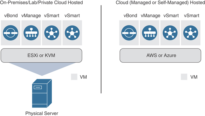
Figure 13-1 Cloud vs. On-Premises
The installation process has a specific order that needs to be followed. Details around this will be discussed in each individual section. The high-level order of operations is as follows:
Step 1. Deploy virtual machines for vManage, vBond, and vSmart.
Step 2. Bootstrap and configure the vManage controller.
Step 3. Bootstrap and configure the vBond controller.
Step 4. Bootstrap and configure the vSmart controller.
Step 5. Install licensing file or sync with Cisco Smart Account.
Note
Retrieving licensing is beyond the scope of this book. Your Cisco Account Team or Partner can answer any questions about licensing.
The Cisco SD-WAN solution strives to achieve the highest level of security, and no component is allowed on the fabric unless it has been authenticated and authorized. There is a detailed process that each of these components goes through when coming online. This is discussed, in detail, in Chapter 3, “Control Plane and Data Plane Operations.” At a high level, each component will authenticate the others using their certificates. Once this process is complete, the control, management, and orchestration planes are established. Full configuration will then be pushed to the vSmart and vBond controllers from vManage.
When controllers are deployed on-premises, special considerations need to be made. If requirements call for deployment of the controllers in a data center, then routing must be in place to reach the vManage, vBond, and vSmart from the WAN Edges. This means that all WAN Edges and controllers must be able to reach the VPN 0 transport interfaces of other solution elements via their own VPN 0 transport interfaces. There are a couple of ways that this can be achieved. Namely, controller VPN 0 prefixes can be leaked into the underlay routing table, or a default route can be installed to influence controller traffic to the data center. By leaking these VPN 0 routes, the controllers will have connectivity between the elements. Alternatively, for deployments where the controllers need to be reachable via the Internet, you can utilize NAT. In such a case, vBond will require a static 1:1 NAT while other controllers can be behind PAT. If you recall, vBond facilitates NAT traversal and detects when other solution elements are behind NAT. Hence, vBond must be directly reachable from the Internet to perform this function. Another option for deployment is to place the controllers in a DMZ, wherein publicly routable addressing is applied directly to the controller VPN 0 interfaces. The same rules apply for routing with this design, however. Specifically, solution elements should have accessibility to these addresses via their VPN 0 transport interface. For transports that don’t need to facilitate control connectivity to the controllers (such as with MPLS, wherein the controllers are only reachable via the Internet), you must restrict control connections via the max-control-connections 0 command. This command is applied to the transport tunnel interface.
Certificates
As discussed in Chapter 4, “Onboarding and Provisioning,” certificates are critical to the secure integrity of the Cisco SD-WAN solution. Not only does the solution use a whitelist model to authenticate the solution components, but each controller also provides its identity via a certificate. Each controller (vManage, vBond, and vSmart) will mutually authenticate each other via these certificates and build their control plane connections. This process is shown in Figure 13-2 but will be discussed in more detail later in this chapter. Likewise, WAN Edges will also validate these certificates to ensure that these controllers are authenticated and authorized.

Figure 13-2 Controller-Based Connectivity
Controllers are administratively defined, and each controller is manually configured to connect to the vBond. It is from this connection that the solution components learn about each other. Two whitelist files are generated and distributed by vManage. The first whitelist is a controller list that is created by manually adding the controllers to the vManage GUI. This list gets distributed to vBond, where it is pushed to the vSmart controllers during the authentication process. The controller list contains the certificate serial numbers for each of the controllers. These serial numbers are used as part of the authentication process. The second whitelist identifies the approved WAN Edges in the environment. This list can be downloaded from the PnP portal at https://software.cisco.com or can be retrieved via the Sync Smart Account mechanism within vManage. Once retrieved, the list is distributed to the other controllers by vManage. Figure 13-3 depicts these two processes.
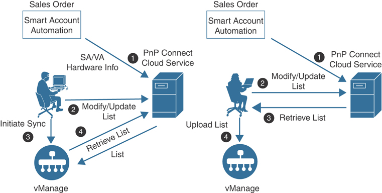
Figure 13-3 Upload WAN Edge List Processes
Before any whitelists can be exchanged, however, controllers must authenticate each other. The following process elaborates on the authentication that occurs. Once authentication is complete, secure control plane connectivity can be achieved and whitelist information can be distributed to controller elements.
First, the controller to be authenticated presents its certificate. Certificate trust will be validated by checking to make sure the certificate presented is signed by a mutually trusted root CA. Note that the root CA certificate chain must be installed on all devices before this can occur. By default, root certificates are already installed for the Symantec, DigiCert, and Cisco CAs. Hence, manually installing the root CA chain is only required when using your own CA. This is a two-way authentication, and each controller authenticates the other one in parallel. See Figure 13-4 for an example between the vBond and vSmart controllers.
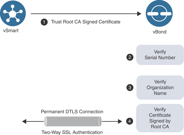
Figure 13-4 Certificate Authentication Process
Inside the sending controller’s certificate is the organization name. This value is checked against the locally configured one. This organization name needs to match enterprise-wide.
The receiving controller verifies the peer’s certificate serial number against the authorized whitelist received from vManage. Note that when the vBond is being authenticated, this serial number is not used.
Obviously, before a controller can authenticate itself with a certificate, it must first obtain one. The first step in obtaining a certificate is to generate a certificate signing request (CSR) from each controller. This process can be done when the controller is added to vManage or the network administrator can perform this operation manually via the controller’s CLI. Once the certificate is signed, it can either be installed manually or automatically on the controller. When onboarding virtual components such as vEdge Cloud devices, things are a little different. vManage will act as a sub-CA to the root CA and sign the certificates for these devices. Figure 13-5 illustrates the automatic enrollment process, though there are multiple ways to perform the certificate signing process:

Figure 13-5 Automatic Enrollment for Symantec/DigiCert Certificates
Automated certificate signing request with Symantec/DigiCert CA: For this option, a CSR is generated via the vManage GUI for each controller and automatically sent to the Symantec/DigiCert CA. Once this is complete, a Cisco CSOne case needs to be opened and the signing request will be authorized. After the signing request is authorized, the Symantec/DigiCert CA will generate certificates. vManage will automatically retrieve the certificate(s) and install them on the corresponding controllers. The root chain for the 499Symantec and DigiCert CA is preloaded with the controller and does not require any additional attention.
Manual certificate signing request with Symantec/DigiCert CA: With the manual option, shown in Figure 13-6, the administrator will generate a CSR for each controller and manually upload the file to the Symantec/DigiCert portal. A CSOne case will then need to be opened and, once the CSR is authorized, the administrator will receive the certificate via email or via download link. The administrator will then need to manually install this certificate via the vManage GUI. vManage will then push the certificate to the relevant controller. This type of deployment would be utilized if the controllers have no Internet connectivity or a firewall is blocking HTTP/HTTPS connectivity to the Symantec/DigiCert portal. As mentioned previously, the root chain for the Symantec and DigiCert CA is preloaded on the controllers and no additional attention is needed.
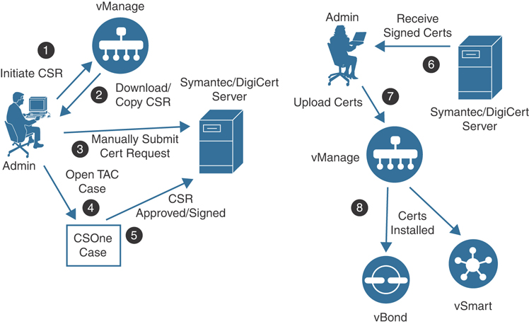
Figure 13-6 Manual Enrollment for Symantec/DigiCert Certificates
Automatic certificate signing request with Cisco PKI CA: This option requires the controllers to be running version 19.1 or later. This option is similar to the automatic Symantec/DigiCert method. The only difference, however, is that once the request is submitted to the Cisco PKI, a CSOne case does not need to be opened. The request will be signed automatically. Likewise, vManage will retrieve and install the certificate for each of the controllers. Figure 13-7 depicts this process. This is the recommended method, as no intervention is needed. As with the Symantec/DigiCert methods, the root chain for the Cisco PKI CA is preloaded with the controller and no additional attention is necessary.

Figure 13-7 Automatic Enrollment for Cisco PKI Certificates
Manual certificate signing request with Cisco PKI CA: This option requires the controllers to be running version 19.1 or later. This option is identical to the automated Cisco PKI method; however, in the absence of Internet connectivity, an administrator will need to manually generate and upload the CSR to the PnP portal at https://software.cisco.com. Once the CSR is authorized, the administrator will need to manually retrieve the certificate(s) from the PnP portal and upload it to vManage, where it will be distributed to the other controllers. Figure 13-8 highlights this process. As with all other options, the root chain for the Cisco PKI CA is preloaded on the controllers and no additional attention is required.
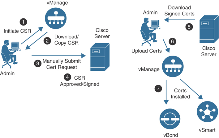
Figure 13-8 Manual Enrollment for Cisco PKI Certificates
Certificate signing request with Enterprise CA: If the deployment will be utilizing an enterprise CA for certificates, the process is similar to the manual steps listed previously with some slight differences. Specifically, the administrator will need to install the root chain from the enterprise CA on each controller. Once this is completed, a certificate signing request can be generated for the corresponding controllers via the vManage GUI. The administrator would then download the CSR and submit the request for signing to the enterprise CA. Once the CSR is authorized and a certificate is generated, the same process noted previously can be used to upload the signed certificate to the vManage GUI for the appropriate controller. Figure 13-9 illustrates this process.

Figure 13-9 Manual Enrollment for Enterprise CA
Note
For the following sections, OpenSSL will be utilized as an enterprise CA.
vManage Controller Deployment
Before the vManage controller can be deployed, the virtual environment must be prepped. The network administrator should plan to have IP address information for the VPN 0 (control plane) interface and the VPN 512 (out-of-band management) interface.
VPN 512 addressing 503is not a requirement but, depending on the design, it may be necessary (especially if the controllers are in an isolated network, such as a DMZ).
For the remainder of this section, we’ll use the subnets noted in Table 13-1.
Table 13-1 Controller Subnets
VPN |
Network |
Subnet Mask |
|---|---|---|
VPN 0 |
209.165.200.224 |
255.255.255.224 |
VPN 512 |
192.168.1.0 |
255.255.255.0 |
In this example, the version being deployed is 19.2; however, the process is the same for earlier versions as well. Consider reviewing the certificate sections discussed previously as well, as there are many options to consider prior to building out the control infrastructure. For our examples, we’ll be using an enterprise CA.
The remainder of this section will cover deployment of the vManage controller on VMware ESXi. Here are the steps being performed:
Step 1. Deploy virtual machine for vManage.
Step 2. Bootstrap and configure vManage controller.
Step 3. Set the organization name and vBond address in vManage.
Step 4. Install the root CA certificate.
Step 5. Generate, sign, and install the certificate onto the vManage controller.
The process to install the vManage virtual machine is similar to deploying any other kind of virtual machine. The Open Virtual Appliances (OVAs) for the controllers can be downloaded from https://www.cisco.com. Once the OVA is deployed, an additional hard disk will need to be added for the database. This drive needs to be at least 100 GB.
Note
At the time of publishing, the OVA location is https://software.cisco.com/download/home/286320995/.
Step 1: Deploy vManage Virtual Appliance on VMware ESXi or KVM
After installing the OVA, right-click on the virtual machine and select Edit Settings (see Figure 13-10).

Figure 13-10 VMware Settings Window
Click the Add button, select Hard Disk, and click Next (see Figure 13-11).
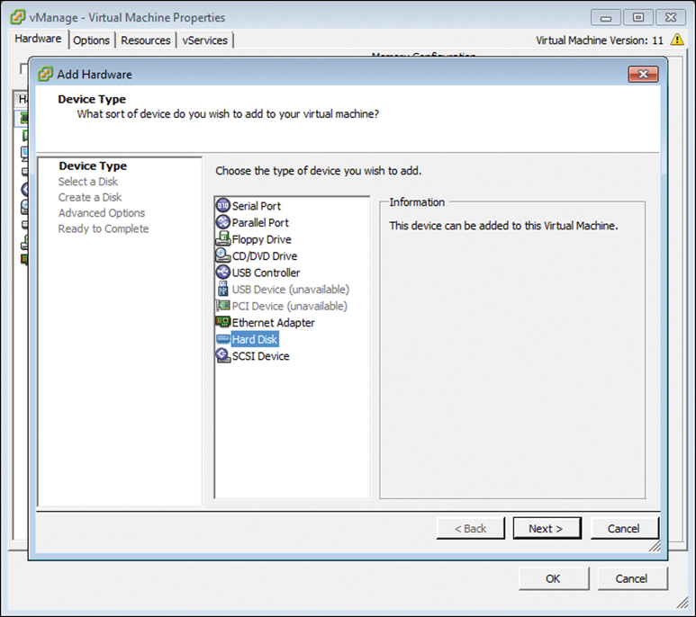
Figure 13-11 Add Hardware Wizard
Select Create a new virtual disk, click Next, and set the size to at least 100 GB. Click Next until you are back to the Virtual Machine Properties window. Click OK to save the settings (see Figure 13-12).

Figure 13-12 Create New Virtual Disk
Once you are finished, power up the virtual machine.
Step 2: Bootstrap and Configure vManage Controller
Now that the vManage virtual machine is properly configured and powered up, the network administrator can begin to configure basic settings.
Open the VMware console for this virtual machine and (once the system prompts you for a login) enter the default username and password of admin. Upon initial login, you will be prompted to format the virtual disk that was just added. Select the disk and type yes to format it. Depending on the size of this virtual disk, it could take some time. Once this process completes, the system will reboot automatically. Figure 13-13 illustrates the initial bootup process.
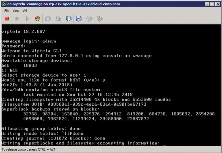
Figure 13-13 Initial Bootup
Step 3/4: Set Organization Name and vBond Address in vManage; Install Root CA Certificate
Now that the virtual disk is formatted, you can begin to apply the initial bootstrap configuration. The initial configuration must contain the following information:
Organization name
System IP
Address of the vBond controller
Site ID
IP address for VPN 0
(Optional) an address for VPN 512
(Optional) NTP server
There are two methods by which to accomplish these tasks. First, you could apply an IP address to the VPN 512 interface and use the vManage GUI to create feature templates that define these parameters. Alternatively, the administrator can input this information via CLI. For our example, we’ll be focusing on the CLI example because it’s generally considered the easiest method. vManage runs Viptela OS, so in some ways the syntax is similar to Cisco IOS.
The system context is where items such as organization name, system IP, site ID, and the address of the vBond controller will be set; optionally, you will want to set an NTP server as well. This will ensure that all your controllers are using the same time. When time isn’t the same across all controllers, you can experience authentication issues between them. To access configuration mode, you will type config terminal or conf t. Once in configuration mode, you will need to navigate to the system context by executing the system command. Example 13-1 provides a sample configuration.
Example 13-1 vManage Initial System Configuration
vmanage# config terminal
Entering configuration mode terminal
vmanage(config)# system
vmanage(config-system)# system
vmanage(config-system)# site-id 100
vmanage(config-system)# system-ip 10.10.10.10
vmanage(config-system)# organization-name "Cisco Press"
vmanage(config-system)# vbond 209.165.200.226
vmanage(config-system)# ntp server 209.165.200.254
vmanage(config-server-209.165.200.254)# vpn 0
Now that the system information has been set, IP address information can be applied. This setup will contain configuration in VPN 0 and VPN 512. As a reminder, VPN 0 is required and will be where control plane connections with other controllers and WAN Edges will be terminated, and VPN 512 will be for out-of-band access. If out-of-band access isn’t required, then VPN 512 configuration is optional. To access these configuration contexts, you simply type the vpn command, followed by the VPN you want to configure. Example 13-2 provides a sample configuration. Note the addition of the tunnel-interface command. This command instructs vManage to use this interface as a transport (control plane) interface.
Example 13-2 vManage VPN 0 and VPN 512 Configuration
vmanage(config-system)# vpn 0
vmanage(config-vpn-0)# interface eth0
vmanage(config-interface-eth0)# ip address 209.165.200.225/27
vmanage(config-interface-eth0)# tunnel-interface
vmanage(config-tunnel-interface)# no shutdown
vmanage(config-tunnel-interface)# ip route 0.0.0.0/0 209.165.200.254
vmanage(config-vpn-0)#
vmanage(config-vpn-0)# vpn 512
vmanage(config-vpn-512)# interface eth1
vmanage(config-interface-eth1)# ip address 192.168.1.10/24
vmanage(config-interface-eth1)# no shutdown
vmanage(config-interface-eth1)# ip route 0.0.0.0/0 192.168.1.254
vmanage(config-vpn-512)#
One difference Viptela OS has with Cisco IOS is that any configuration changes are not actually applied until you commit them. Cisco IOS XR has this feature as well. Inside Viptela OS, you can check your candidate config by running the show config command. There are many benefits to this, such as allowing for building out configuration and checking for syntax issues prior to activation. With classical Cisco IOS, all changes made in configuration mode are instantly applied, which could potentially cause an outage. Example 13-3 provides a sample configuration.
Example 13-3 Commit Configuration Changes
vmanage(config-vpn-512)# commit [and-quit]
Commit complete
vmanage#
Now that the initial bootstrap configuration has been applied, we can connect to the vManage GUI and finalize the bootstrap process. As discussed, we will use the enterprise CA method of certificate enrollment in this example. Refer to the previous section for information about other methods.
Connect to the VPN 512 IP address via a web browser and log in with the username of admin and a password of admin. Once you’re logged in, the system presents you with a dashboard. This dashboard provides a quick overview on the state of the SD-WAN deployment, as depicted in Figure 13-14.
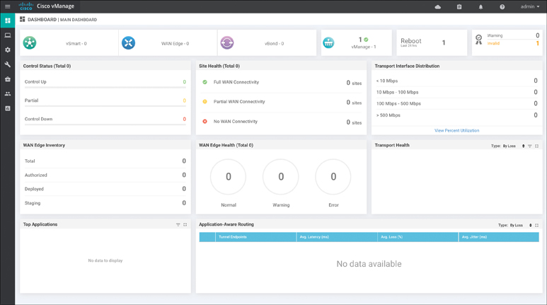
Figure 13-14 vManage Dashboard
From the menu bar on the left of the screen, click the Administration icon and select Settings (see Figure 13-15).

Figure 13-15 vManage Menu Bar
On the page that follows, navigate to the Organization Name, vBond address, and the Controller Certificate Authorization fields. Click on each of these items and select Edit. Here are the values that will be used:
Organization Name: Cisco Press
vBond: 209.165.200.226
Controller Certificate Authorization: Enterprise CA
Figure 13-16 highlights how to edit these settings in vManage.

Figure 13-16 vManage Settings
The last step that needs to be done is to change the Controller Certificate Authorization mode. Click Edit and select enterprise CA. In the box that appears, you can either upload or paste in the root CA certificate file. You might need to obtain this file from your enterprise PKI administrator. See Figure 13-17 for this process. Note that you also have the option to set the CSR properties for all CSR requests by selecting Set CSR Properties.
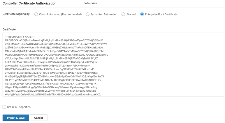
Figure 13-17 vManage Settings
Note
Once devices have been added to vManage, the organization name cannot be changed.
Step 5: Generate, Sign, and Install Certificate onto vManage Controller
The final step is to generate the certificates that will be used for vManage controller authentication.
Browse to the Devices Configuration section. From here, select Certificates. Select the Controllers tab at the top. Figure 13-18 shows these steps in vManage.
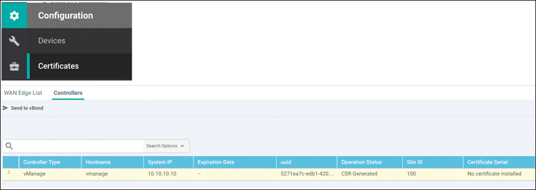
Figure 13-18 vManage Certificate Settings
From here, you can see additional information about the vManage controller. Note the Certificate Status column. From this screen we can also regenerate a CSR and install a certificate. Since the CSR is automatically generated by vManage, we’ll download and have the enterprise CA sign it. From there, we’ll install the signed certificate into the controller. To download the CSR, click the ellipsis to the far right for the respective controller. Figure 13-19 highlights the necessary pane within vManage.

Figure 13-19 Download CSR
Select View CSR. From here, the CSR is displayed and you have the option to copy or download the text. Copy or download this file and submit to your Enterprise PKI administrator. Once this CSR has been submitted and signed by the enterprise CA, we can continue with installation. Figure 13-20 shows the CSR properties window within vManage.
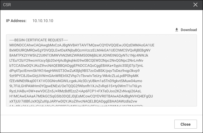
Figure 13-20 View CSR Properties Window
Once the certificate has been generated and signed by the root CA, you can install the certificate into the controller. In the right-hand corner of the main screen, locate the button that says Install Certificate. From here, you are prompted to either paste the contents of or upload the certificate. Click Install, as shown in Figure 13-21.

Figure 13-21 Install Certificate Window
At this point, a status window appears allowing you to track the progress of certificate installation. The final output should display Success.
In this section, initial deployment of the vManage controller was completed. The controller was manually bootstrapped via the CLI, and the configuration was finished via the vManage GUI. This included using an enterprise CA to handle certificate enrollment. Now that the vManage controller is deployed, the administrator can move on to deploying the rest of the control plane.
vBond Controller Deployment
Now that the vManage controller has been deployed, we can begin with the vBond controller. Remember that the vBond performs a critical function in the SD-WAN deployment, as it orchestrates or glues all other components together. vBond is how WAN Edges find out about the various vManage and vSmart controllers and acts as the first line of authentication and authorization into the fabric. WAN Edges do not sustain a permanent connection to the vBond. Rather, the connection to vBond is transient. WAN Edges must be able to reach the vBond controller on all VPN 0 transports by default.
For environments that utilize the Internet as a transport, it is strongly recommended to place the vBond in a DMZ with a public IP address. Provided that vBond has a public IP address, the vSmart, vManage, and WAN Edge routers can remain behind a secured gateway performing NAT. The vBond then performs NAT detection and traversal for these devices. Refer to the NAT section in Chapter 3 for further information on this. Again, if the vBond must be behind NAT, it must be a static 1:1 NAT.
For the remainder of this section, we’ll use the subnets noted in Table 13-2.
Table 13-2 Controller Subnets
VPN |
Network |
Subnet Mask |
|---|---|---|
VPN 0 |
209.165.200.224 |
255.255.255.224 |
VPN 512 |
192.168.1.0 |
255.255.255.0 |
This section will cover deployment of the vBond controller. Here are steps to be performed:
Step 1. Deploy the virtual machine for vBond.
Step 2. Bootstrap and configure the vBond controller.
Step 3. Manually install the root CA certificate on vBond.
Step 4. Add the vBond controller to vManage.
Step 5. Generate, sign, and install the certificate onto the vBond controller.
The examples in this section cover deployment with version 19.2. Note that there is no specific vBond OVA because it uses the same OVA as vEdge Cloud. Hence, when the vEdge Cloud OVA is deployed, the persona is changed to be a vBond. For this deployment, the VPN 0 and VPN 512 IP addresses need to be assigned.
Note
At the time of publishing, the OVA location is https://software.cisco.com/download/home/286320995/.
Step 1/2/3: Deploy vBond Virtual Machine on VMware ESXi; Bootstrap and Configure vBond Controller; Manually Install Root CA Certificate on vBond
Once the vBond virtual machine is deployed, power up the virtual machine.
Similar to the vManage controller, you need to apply a bootstrap configuration via the CLI. In this step you’ll set the organization name, site ID, system IP, VPN 0, and VPN 512 information. As with vManage, the first thing you’ll do on vBond is set the system information. To access this configuration mode, type config terminal or conf t. Once in configuration mode, to access the system context, execute the command system. Pay special attention to the vbond 209.165.200.226 local command. Remember that we’re using the vEdge Cloud image for the vBond. By specifying the local command, the vBond persona is enabled. Example 13-4 lists the initial system configuration.
Example 13-4 vBond Initial System Configuration
vedge# config terminal
Entering configuration mode terminal
vedge(config)# system
vedge(config-system)# system
vedge(config-system)# host-name vbond
vedge (config-system)# site-id 100
vedge(config-system)# system-ip 10.10.10.11
vedge(config-system)# organization-name "Cisco Press"
vedge(config-system)# vbond 209.165.200.226 local
vedge(config-system)# ntp server 209.165.200.254
vedge(config-server-209.165.200.254)# vpn 0
Just like with the vManage controller, you need to provide some initial settings to the VPN 0 and VPN 512 interfaces. One difference from the vManage controller is that you need to remove the tunnel tunnel-interface command. This process is shown in Example 13-5.
Example 13-5 vBond VPN 0 and VPN 512 Configuration
vedge(config-system)# vpn 0
vedge (config-vpn-0)# interface ge0/0
vedge(config-interface-ge0/0)# ip address 209.165.200.226/27
vedge(config-interface-ge0/0)# no tunnel-interface
vedge(config-interface-ge0/0)# no shutdown
vedge(config-interface-ge0/0)# ip route 0.0.0.0/0 209.165.200.254
vedge(config-vpn-0)#
vedge(config-vpn-0)# vpn 512
vedge(config-vpn-512)# interface eth0
vedge(config-interface-eth0)# ip address 192.168.1.11/24
vedge(config-interface-eth0)# no shutdown
vedge(config-interface-eth0)# ip route 0.0.0.0/0 192.168.1.254
vedge(config-vpn-512)#
As discussed previously, you need to save your configuration. This is completed by committing the configuration using the commit command, as depicted in Example 13-6.
Example 13-6 Commit Configuration Changes
vedge(config-vpn-512)# commit [and-quit]
Commit complete
vbond#
The last step to initially bootstrap the vBond controller is to install the root CA certificate. To complete this, you need to copy the root CA certificate to the vBond controller. This can be most easily accomplished with SCP (such as with Putty SCP or WinSCP). Simply use the SCP program of your choice to connect to the VPN 512 interface of vBond and copy the root certificate over. By default, the file is copied to the /home/admin directory on the vBond. Once copied, however, the certificate needs to be installed. This is accomplished via the request root-cert-chain install directory command, as demonstrated in Example 13-7.
Example 13-7 Root Certification Chain Install
vbond# request root-cert-chain install /home/admin/rootca.pem
Uploading root-ca-cert-chain via VPN 0
Copying ... /home/admin/rootca.pem via VPN 0
Updating the root certificate chain..
Successfully installed the root certificate chain
vbond#
Step 4/5: Add vBond Controller to vManage; Generate, Sign, and Install Certificate onto vBond Controller
The remainder of vBond bootstrapping can be done via the vManage GUI. In these steps, the network administrator will be adding the vBond controller to the SD-WAN overlay (that is, updating the whitelist discussed previously). Most notably, this will consist of generating a CSR, signing the CSR, and installing the certificate.
Adding the vBond to the controller whitelist is done via the vManage GUI. Once you’re logged in to the vManage GUI, browse to Configuration > Devices > Controllers (tab). From here, select Add Controller and select vBond, as illustrated in Figure 13-22.
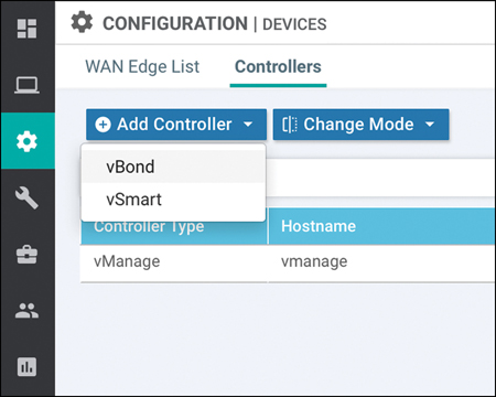
Figure 13-22 Add vBond Controller to vManage
A dialog box will be displayed. From this screen, input the management IP (VPN 512) as well as the username and password. For this example, the default values are 192.168.1.11 and admin/admin. Click Add when finished. By leaving Generate CSR checked, a CSR will automatically be created. Figure 13-23 showcases the necessary steps to accomplish this.

Figure 13-23 Add vBond Controller to vManage Controller
You should now see the vBond controller added to the vManage GUI. Figure 13-24 shows the successful addition of the vBond.

Figure 13-24 Add vBond Controller to vManage Controller
The final step is to generate the certificates that will be used for vBond controller authentication. Browse to the Devices > Certificates > Controllers screen in the GUI.
Just like we did with vManage, we need to download and sign the CSR. To download the CSR, click the ellipsis to the far right for the respective controller and select View CSR. A dialog box will appear. From here, you can download the CSR and have the enterprise CA sign the request.
Once this is complete, you can install the certificate. The process is exactly the same as with the vManage controller described previously. If everything was successful, you should see a screen similar to the one depicted in Figure 13-25.

Figure 13-25 Install Certificate on vBond Controller
From the Configuration > Devices > Certificates > Controllers screen that is shown in Figure 13-26, we can now see that the vBond is in sync and vManage has learned additional values from the device (such as site ID and system IP).

Figure 13-26 Controller Certificate Screen
In this section, the vBond controller was deployed, bootstrapped, and configured and certificates were installed. The next section will cover deployment of the vSmart controller. The process for the vSmart controller is very similar to the vBond controller.
vSmart Controller Deployment
Now we have deployed the vManage and vBond controllers, the final controller to deploy is vSmart. The process is very similar to the vBond controller. After deploying the OVA, we need to provide basic bootstrap configuration, install the root CA certificate, add the controller to vManage, and facilitate certificate installation. When we add the controller, vManage will use Netconf to connect. Hence, when we add the tunnel-interface command, we’ll have to apply one additional line of configuration to allow Netconf access. The process is the same if we are deploying one vSmart controller or multiple vSmart controllers. For this example, we’ll be focusing on version 19.2 of the vSmart controller. The OVA for vSmart can be downloaded from https://www.cisco.com.
For the remainder of this section, we’ll use the subnets noted in Table 13-3.
Table 13-3 Controller Subnets
VPN |
Network |
Subnet Mask |
|---|---|---|
VPN 0 |
209.165.200.224 |
255.255.255.224 |
VPN 512 |
192.168.1.0 |
255.255.255.0 |
The remainder of this section will cover deployment of the vSmart controller, using the following steps:
Step 1. Deploy the vSmart virtual machine from the downloaded OVA.
Step 2. Bootstrap and configure the vSmart controller.
Step 3. Manually install the root CA certificate on vSmart.
Step 4. Add the vSmart controller to vManage.
Step 5. Generate, sign, and install the certificate onto the vSmart controller.
Step 1/2/3: Deploy vSmart Virtual Machine from Downloaded OVA; Bootstrap and Configure vSmart Controller; Manually Install Root CA Certificate on vSmart
Install the vSmart OVA onto VMware ESXi or KVM and power up the VM. The default username and password are admin.
Now that the OVA is installed and powered up, let’s apply the initial bootstrap configuration. Just like with the vBond controller, you first need to configure system options (such as site ID, system IP, organization name, and vBond address). Additionally, in Example 13-8, we’ll apply the VPN 0 and VPN 512 interface information.
Example 13-8 vSmart Initial System Configuration
vsmart# config terminal
Entering configuration mode terminal
vsmart(config)# system
vsmart(config-system)# system
vsmart(config-system)# site-id 100
vsmart(config-system)# system-ip 10.10.10.12
vsmart(config-system)# organization-name "Cisco Press"
vsmart(config-system)# vbond 209.165.200.226
vsmart(config-system)# ntp server 209.165.200.254
vsmart(config-server-209.165.200.254)# vpn 0
Next on the list is to configure the VPN 0 context. This configuration is slightly different from vBond configuration, however. When the tunnel-interface command is applied, a firewall is enabled (since it is assumed that this interface will be connected to untrusted networks). By default, Netconf is blocked. Since vManage uses Netconf to initially connect as well as push configuration, we need to allow this. Unblocking Netconf is accomplished with the command allow-service netconf under the tunnel-interface. Example 13-9 lists these steps.
Example 13-9 vSmart VPN 0 and VPN 512 Configuration
vsmart(config-system)# vpn 0
vsmart(config-vpn-0)# interface eth0
vsmart(config-interface-eth0)# ip address 209.165.200.227/27
vsmart(config-interface-eth0)# tunnel-interface
vsmart(config-tunnel-interface)# no shutdown
vsmart(config-tunnel-interface)# ip route 0.0.0.0/0 209.165.200.254
vsmart(config-tunnel-interface)# allow-service netconf
vsmart(config-vpn-0)#
vsmart(config-vpn-0)# vpn 512
vsmart(config-vpn-512)# interface eth1
vsmart(config-interface-eth1)# ip address 192.168.1.12/24
vsmart(config-interface-eth1)# no shutdown
vsmart(config-interface-eth1)# ip route 0.0.0.0/0 192.168.1.254
vsmart(config-vpn-512)#
As we did with the vManage and vBond controllers, we need to save our commands. The commit command is used to accomplish this and is highlighted in Example 13-10.
Example 13-10 Commit Configuration Changes
vsmart(config-vpn-512)# commit [and-quit]
Commit complete
vsmart#
Next, the network administrator needs to manually install the root CA certificate. This is most easily achieved by copying the file to the vSmart controller using your favorite SCP program. By default, the file is copied to the /home/admin directory on the vSmart controller. Once this file is copied, the certificate needs to be installed. This is accomplished via the request root-cert-chain install <directory> command, as shown in Example 13-11.
Example 13-11 Root Certification Chain Install
vsmart# request root-cert-chain install /home/admin/rootca.pem
Uploading root-ca-cert-chain via VPN 0
Copying ... /home/admin/rootca.pem via VPN 0
Updating the root certificate chain..
Successfully installed the root certificate chain
vsmart#
Step 4/5: Add vSmart Controller to vManage; Generate, Sign, and Install Certificate onto vSmart Controller
The remaining bootstrap steps will be performed from the vManage GUI. The process is identical to the vBond controller to add the vSmart controller.
First, browse to Configuration > Devices > Controllers from the vManage GUI. From here, select Add Controller and select vSmart. Figure 13-27 illustrates the process.
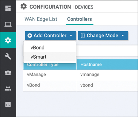
Figure 13-27 Add vSmart Controller to vManage
A dialog box will appear asking for vSmart’s IP address, username, and password. You also have the option to use either DTLS or TLS. By default, we use DTLS. Leave the Generate CSR box checked. Figure 13-28 demonstrates the correct fields to configure within the vManage.

Figure 13-28 Add vSmart Controller to vManage Controller
If completed successfully, you should see the vSmart controller added with a certificate status of Not-Installed, as shown in Figure 13-29.

Figure 13-29 Add vSmart Controller to vManage Controller
The next step is to download the CSR, have it signed, and install the corresponding certificate. Figure 13-30 displays the process in the vManage controller. To access this screen, browse to Configuration > Certificates > Controllers. Once on this screen, click the ellipsis to the right of the vSmart controller and select View CSR. Copy the CSR to a text file or download the CSR.

Figure 13-30 Download CSR for vSmart Controller
The final step is to install the signed certificate. As we did with the vBond and vManage controllers, select Install Certificate in the upper right-hand corner. A dialog box will appear. Either paste the contents of the certificate into the window or select the certificate file using the Select a file button. Once it is uploaded, click Install. Figure 13-31 highlights the step in vManage to install the vSmart controller certificate.

Figure 13-31 Install Signed Certificate for vSmart Controller
If successful, you should see a status screen stating that the certificate was installed. Navigating to Configuration > Devices > Controllers, as shown in Figure 13-32, you can see that some additional information has been learned about the vSmart controller.

Figure 13-32 Install Signed Certificate for vSmart Controller
Now that the vSmart controller is deployed, we have a fully functional SD-WAN overlay. The process to add additional vSmart controllers is exactly the same, should you need to revisit these steps in the future. At this point, you can begin building templates and policies and start onboarding WAN Edges.
Summary
This chapter discussed how certificates are utilized in an SD-WAN fabric and also how to deploy the SD-WAN control plane, management plane, and the orchestration plane. From this information, an engineer can deploy the solution in a private cloud, on-premises, or lab deployment.
The first section covered the importance of certificates and the critical function they play with authentication and authorization. When controllers are brought online, they mutually authenticate each other and check the attributes of exchanged certificates. Only if these attributes match will the controllers be able to build connections to each other. Certificates can be managed via multiple methods, such as automatic enrollment with Symantec/DigiCert, manual enrollment with Symantec/DigiCert, automatic enrollment with Cisco PKI, manual enrollment with Cisco PKI, and finally utilizing an enterprise CA. Starting with version 19.1 of the SD-WAN software, using automatic enrollment with Cisco PKI is the preferred mechanism because the management and support are seamless.
The final sections covered deployment of the SD-WAN controllers in a virtualized environment. Starting with the management plane, vManage was deployed and configured. Second, the orchestration plane was deployed with vBond. Finally, the control plane was deployed with the vSmart controller. This process consisted of deploying the virtual machines, initial bootstrap configuration, and adding the controllers to vManage.
Review All Key Topics
Review the most important topics in the chapter, noted with the Key Topic icon in the outer margin of the page. Table 13-4 lists these key topics and the page numbers on which each is found.
Table 13-4 Key Topics
Key Topic Element |
Description |
Page |
|---|---|---|
Section |
Certificates |
496 |
Section |
vManage Controller Deployment |
501 |
Section |
vBond Controller Deployment |
513 |
Section |
vSmart Controller Deployment |
518 |
Define Key Terms
Define the following key terms from this chapter and check your answers in the glossary:
Chapter Review Questions
1. What are the three controllers that make up the Cisco SD-WAN solution?
vSmart
vBond
WAN Edge
vManage
vController
2. What are the three main certificate deployment options?
Automatic enrollment with Symantec/DigiCert/Cisco PKI
Manual enrollment with Symantec/DigiCert/Cisco PKI
Self-signed certificates
SSH private/public keys
Enterprise CA
3. Which controller is deployed first?
vManage
vSmart
vBond
WAN Edge
vCompute
4. If the vBond controller is behind a NAT, it must have a 1:1 static NAT.
True
False
5. Which three attributes are verified when authenticating the certificate?
Organization name
Trust of certificate
Common name
City
Certificate serial number
6. Which command is a valid command to enable the vBond persona?
vbond 209.200.165.227 local
vbond 209.200.165.227 enable
feature vbond
7. What protocol does vManage use to push configuration to vSmart?
Netconf
SSH
Telnet
Feature Templates
8. Which command is used to save configuration changes?
commit
copy running-config startup-config
save
write memory
BGP
9. What is the order in which the controllers are installed?
vManage > vBond > vSmart
vBond > vManage > vSmart
vSmart > vBond > vManage
WAN Edge > vBond > vSmart > vManage
10. Which command is used to allow Netconf through the inherent firewall on the vSmart controller?
allow-service netconf
permit netconf any any
enable-service netconf
feature netconf
References
“Cisco SD-WAN CVD–Certificate Deployment,” https://www.cisco.com/c/dam/en/us/td/docs/solutions/CVD/SDWAN/cisco-sd-wan-certificates-deploy-2019sep.pdf, September 2019
“Cisco SD-WAN Bring Up Sequence of Events,” https://sdwan-docs.cisco.com/Product_Documentation/Getting_Started/Viptela_Overlay_Network_Bringup/01Bringup_Sequence_of_Events