
Chapter 2. Cisco SD-WAN Components
This chapter covers the following topics:
Data Plane: This section discusses the physical and virtual routers that actually carry data traffic.
Management Plane: This section of the chapter introduces the component that handles most of our day-to-day tasks in managing the Cisco SD-WAN fabric.
Control Plane: This section covers the component that handles all policies and routing.
Orchestration Plane: This section introduces the component that facilitates discovery, authentication, and facilitation of the fabric.
Multi-Tenancy Options: This section introduces the various multi-tenancy options in the Cisco SD-WAN solution.
Deployment Options: This section covers the various deployment options, including Cisco cloud, private cloud, and an on-premises deployment.
This chapter introduces the various components that make up the Cisco SD-WAN architecture as well as the various deployment options. At a high level, these components can be grouped together by what purpose they play in the Cisco SD-WAN solution:
Data Plane
Management Plane
Control Plane
Orchestration Plane
In traditional networks today, the management plane, data plane, and control plane are all on the same router, and together they facilitate communication within the network. On a traditional router, we have line cards (which handle switching and forwarding of our data packets), a CPU module (which handles calculating our route table and advertising networks to the rest of the network), and the command line interface (CLI) is used to program the router. On the CLI, we type commands, and those commands program the CPU and line cards to act on our intent. Each router in a network has these three components. When you look at a traditional network, you have a number of routers, each of which needs to be programmed independently to achieve the desired operational state of your network. As these networks get larger, the amount of human intervention required to configure this environment dramatically increases, potentially creating complexity. Each router must calculate its own routing table from its perspective of the network. For example, suppose you have a network with 6,000 routes. Whenever there is a change in the network, each router will have to process these routing updates for each of these routes potentially. This requires the router to have the necessary available CPU and memory requirements to process these updates, which in turn creates a lot of overhead. Tuning the routing table on a network with a large number of sites and routes can quickly become very complex to achieve the desired results—be it full mesh, hub and spoke, partial mesh, and so on. Additionally, because each router is programmed individually, when you program the network on a router-by-router basis, you run the risk of undesired results due to an improper design or human error on the CLI.
The Cisco SD-WAN solution is a distributed architecture, meaning Cisco has separated the data plane from the control plane and management plane. Figure 2-1 illustrates how all the components fit into the architecture.

Figure 2-1 Cisco SD-WAN Distributed Architecture
This architecture differs from traditional networking in that it allows you to support large-scale networks while reducing operational and computational overhead. This solution separates the data plane, control plane, and management plane from each other. Because the control plane knows about all routes and nodes on the network, you have to calculate the routing table only once and can distribute this to all the necessary nodes as a single routing update rather than have every router send routing updates to the others, with each determining its own Routing Information Base (RIB). This greatly reduces the overhead on the network and enables you to reduce required resources on the routers so that you can bring additional features and capabilities to your edge devices. Because you have a complete view of the network, you can create a common network policy across the entire SD-WAN fabric—with the need for the management plane to program it once. As new devices are added to the network, they receive the same policy as well, ensuring the network is operating as expected. This book will show you how you can create various topologies and policies with ease, while increasing scale and capability.
Data Plane
Traditionally, the data plane is composed of the physical interfaces that our physical layer plugs into (for example, Ethernet, fiber and serial, and so on). As mentioned previously, this is analogous to the line cards on routers and switches. The Cisco SD-WAN solution refers to the data plane as WAN Edges. WAN Edges could be Cisco vEdge routers or Cisco XE SD-WAN routers. Throughout this section, you will learn the differences and features that these two platforms bring and how to select which one meets your business requirements. Data plane devices are deployed at branches, data centers, large campuses, colocation facilities, or in the cloud. At each site you can have a single WAN Edge or multiple WAN Edges, depending on redundancy requirements.
The data plane is where the SD-WAN overlay resides and is the layer that forwards user, server, and other network traffic. Both IPv4 and IPv6 are supported for transport within the data plane. In addition, data policies (such as QoS, Application-Aware Routing, and so on) are enforced within the data plane.
Each router will form data plane connections to other routers within the SD-WAN overlay for the purposes of transporting user traffic. Data plane connections are only established between data plane devices. These tunnels are secured via Internet Protocol Security (IPsec). As described previously, the data plane has native segmentation. The original IPv4/IPv6 payload is encapsulated utilizing RFC 4023. By using RFC 4023, you have segmentation across the SD-WAN overlay. Segmentation allows the network administrator to build separate instances of the data plane, depending on business requirements and regulations. The original data packet is encapsulated with IPsec, providing encryption and authentication. Figure 2-2 depicts the SD-WAN header representation.
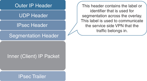
Figure 2-2 Cisco SD-WAN Packet Format
The Cisco SD-WAN solution can support diverse topologies unique to each VPN segment or data plane instantiation. Each of these VPN segments is completely isolated from communicating with each other unless policy allows it. These VPNs are carried in a single IPsec tunnel. For example, corporate users could have a full-mesh topology while PCI or HIPAA requirements could dictate that you have a hub-and-spoke topology for other devices. Figure 2-3 provides a graphical representation of this concept. On the LAN, or service side, the data plane supports OSPF, EIGRP, and BGP for routing protocols. For smaller locations that don’t utilize a routing protocol, VRRP is supported to provide first-hop gateway redundancy.

Figure 2-3 Segmentation and Per VPN Topologies
Note
In the Cisco SD-WAN solution, Virtual Private Network (VPN) is synonymous with Virtual Routing and Forwarding (VRF) instances from a generic routing perspective. VRFs and VPNs provide a method to separate the control and data plane into different logical parts. Segmentation in the data plane is accomplished by building multiple, isolated routing table instances and binding specific interfaces to those instances.
WAN Edges have built-in security to prevent unauthorized access from the network. The WAN-facing interfaces only allow connections from authenticated sources, such as control plane and management plane elements. These interfaces explicitly allow IPsec connections only from other WAN Edges in the fabric. The WAN Edges learn of these other data plane devices from the control plane elements in the solution. The WAN-facing interface firewall on the WAN Edge, by default, will block everything that isn’t allowed explicitly. Inbound services that can be enabled are SSH, NETCONF, NTP, OSPF, BGP, and STUN. Outbound services that are allowed are DHCP, DNS, and ICMP.
Bidirectional Forwarding Detection (BFD) is used inside IPsec tunnels between all WAN Edges. BFD sends Hello packets to measure link liveness as well as packet loss, jitter, and delay. Each WAN Edge will make its own determination on how to react to this BFD information. Depending on the policy defined by the management plane, routing across the data plane could be adjusted, such as having applications prefer one transport over the other, depending on performance. BFD operates in echo mode, which means that the neighbor doesn’t actually participate in the processing of the BFD packet; instead, it is simply echoed back to the original sender. This greatly reduces the impact on the CPU, as the neighbor doesn’t need to process the packets. By comparison, if the neighbor was involved in the processing of the BFD packets, and the remote neighbor’s CPU was busy with some other processing, there could be potential delay in responding to the BFD packet. By eliminating this, you can reduce outage detection time and improve user experience. BFD cannot be turned off, but timers can be tuned in the SD-WAN fabric to identify and illicit a response to potential issues more quickly. Another advantage of using echo mode is that the original packet is echoed back to the original sender, and from this information the WAN Edge has a complete round-trip view of the transport.
When the WAN Edge initially gets connected to the network, it first tries to reach out to a Plug and Play (PNP) or Zero Touch Provisioning (ZTP) server. Figure 2-4 illustrates a high-level overview of the PNP/ZTP process. This process will be discussed further in Chapter 4, “Onboarding and Provisioning,” but for now know that this is the process in which the router connects to the orchestration plane and learns about all of the various components in the network. Once the control plane is established, the last step is to build data plane connections to all other WAN Edges. By default, a full-mesh topology will be built, though policy can be built to limit data plane connections and influence the routing topology. It should be noted, as well, that if PNP or ZTP isn’t available, there are other options available to manually bootstrap the configuration using the CLI or a USB thumb drive.

Figure 2-4 High-level Overview of the Plug and Play/Zero Touch Provisioning Process
Note
There are two methods of auto-provisioning of WAN Edges: PNP and ZTP. PNP uses HTTPS to connect to Cisco PNP servers, and ZTP uses UDP port 12346 to connect. Cisco XE SD-WAN routers use PNP, while Cisco vEdges use ZTP for provisioning.
There are two methods of deployment—physical and virtual. Physical platforms that are supported are the Cisco Integrated Services Router (ISR), Cisco Advanced Services Router (ASR), and Cisco vEdges. Virtual platforms are supported on public or private clouds. Supported virtual platforms are the Cisco Cloud Services Router (CSR1000v) running XE SD-WAN and Cisco vEdge Cloud. At press time, supported public clouds are Amazon Web Services, Google Cloud and Microsoft Azure. Virtual platforms can also be deployed on a private cloud, which can run either on VMware ESXi or KVM hypervisors. If the use case requires it, virtual platforms can be supported at the branch as well via the Cisco Enterprise Network Compute System (ENCS) and Cisco Cloud Services Platform (CSP). These platforms open the door to provide service chaining with VNFs—including firewalls and third-party virtual appliances. Table 2-1 outlines the supported WAN Edge platforms.
Table 2-1 Current SD-WAN Supported Platforms
Cisco XE SD-WAN Platforms |
Cisco vEdge Platforms |
Virtual Platforms |
|---|---|---|
Cisco ISR1000 Series |
Viptela 100 Series |
Cisco CSR1000v |
Cisco ISR4000 Series |
Viptela 1000 Series |
Viptela vEdge Cloud |
Cisco ASR1000 Series |
Viptela 2000 Series |
Cisco ISRv |
Cisco ENCS |
Viptela 5000 Series |
|
Cisco CSP |
|
|
Check https://www.cisco.com/c/en/us/solutions/enterprise-networks/sd-wan/index.html for the complete supported list of platforms.
When considering which WAN Edge to go with, you will need to understand your throughput requirements, data plane tunnel requirements (for example, how many other branches the router will be communicating with), and what type of interfaces are needed. Cisco vEdge platforms support Ethernet, LTE, and wireless interfaces, while Cisco XE SD-WAN platforms support additional interface types, including voice and serial inter-faces. Both platforms are interoperable on the SD-WAN fabric and can terminate data plane tunnels between XE SD-WAN and vEdge platforms.
Viptela platforms run Viptela OS. Cisco SD-WAN platforms run IOS-XE SD-WAN software. If there is an existing deployment of Cisco ISRs and ASRs, then you can leverage this existing investment and upgrade them from IOS-XE to an IOS-XE SD-WAN image in the same way you would upgrade any other Cisco router.
Note
Upgrading Cisco IOS-XE to IOS-XE SD-WAN may require a ROMMON upgrade as well. You can find more information on the procedure to upgrade Cisco IOS-XE routers at https://www.cisco.com/c/en/us/td/docs/routers/sdwan/configuration/sdwan-xe-gs-book/hardware-and-software-installation.html.
Some of the most important features supported on XE SD-WAN routers are advanced security use cases. By overlaying security on top of the Cisco SD-WAN solution, you can introduce new Direct Internet and Direct Cloud Access use cases at the branch, in addition to securing traffic within the overlay. Moving security to the branch facilitates the capability to leverage existing Internet transports at the branch. This is referred to as Direct Internet Access (DIA), or sometimes as Local Internet Access. Figure 2-5 illustrates these concepts.
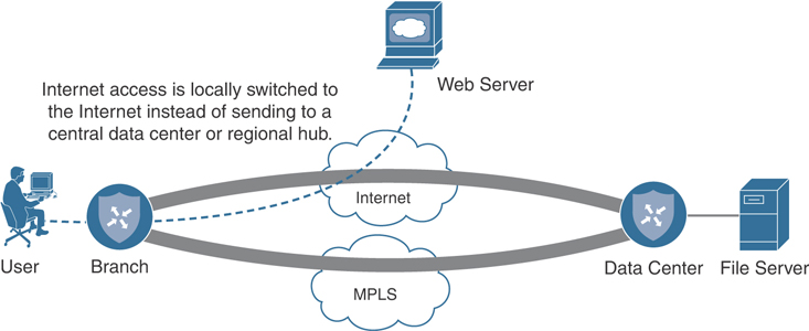
Figure 2-5 Direct Internet Access Overview
Security use cases will be discussed in more detail in Chapter 10, “Cisco SD-WAN Security,” but here is a list of currently supported security features:
DNS Security (Cisco Umbrella)
Endpoint Protection (Cisco AMP for Endpoints)
Application-Aware Firewall
Intrusion Detection System/Intrusion Prevention System
URL Filtering
Traditionally, security requirements dictate that all Internet access is backhauled to a data center, colocation, or regional site. The reason for this was due to the fact that it was more cost-effective to implement security at a central site due to the cost of implementing and managing disparate security components at all sites. With Cisco SD-WAN security, businesses can move security to the branch and can now offload Internet access at remote sites. Here are some other areas where a business might see benefits from DIA:
Reduced bandwidth requirements and latency on costly WAN circuits
Guest access
Improved user experience to Cloud SAAS and IAAS applications
Chapter 7, “Centralized Data Policies,” discusses DIA in more detail.
When a WAN Edge attempts to join the fabric, it attempts to build control connections across each transport deployed at that site. By default, if a transport doesn’t have control connectivity to any of the Cisco SD-WAN controllers, then it won’t build a data plane connection across that transport either. This is very common with cloud deployments where the controllers are in a public or private cloud and your MPLS transport has no connectivity to the Internet.
Note
There are a few options to still achieve data plane with no control connectivity. One option is to disable control connections on that transport via the max-control-connections command. Be aware that when control connections aren’t established on an interface, there will be no control plane monitoring over that transport. You still have monitoring from a data plane perspective, however.
Management Plane
As mentioned previously, network devices of the past would be managed via the CLI independently. Cisco SD-WAN, however, introduces vManage, which is a network management system (NMS) that provides a single pane of glass to manage the SD-WAN solution. vManage can be utilized for onboarding, provisioning, policy creation, software management, troubleshooting, and monitoring. Though vManage has a rich feature set, if the preference is to interface with vManage via an API, vManage also supports communication via REST and NETCONF. By having a full API, the user can build and utilize scripts and interface with vManage in an automated fashion. This API also allows the user to use existing and future toolkits for integration. As you can see in Figure 2-6, vManage provides an intuitive and easy-to-consume dashboard. When first logging in to vManage, you will be presented with statistics outlining what the current state of the network is.
vManage is also highly scalable, depending on the needs of the environment. When vManage is clustered, redundancy can be provided, with multiple clusters deployed regionally or globally. A single cluster is made up of three or more vManage NMSs but must always be an odd number to avoid a split-brain scenario. A vManage cluster can manage up to 6,000 WAN Edges, with each cluster node handling 2,000 WAN Edges.
vManage can use multiple authentication sources, including RADIUS, TACACS, and SAML 2.0 for external user connectivity. By default, vManage is deployed in a single tenant mode, though, if the requirements call for support of a service provider model, multi-tenancy is supported as well.
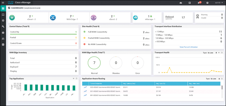
Figure 2-6 Cisco vManage Overview
All configuration for the SD-WAN fabric should be performed within vManage in order to maintain consistency and scalability. Discussed further in Chapter 4, device configurations are built in vManage via feature or CLI templates. Policies, controlling things such as network topology, routing, QoS, and security, are also configured here. When necessary, vManage is also where troubleshooting and monitoring of the network will occur. Network administrators can simulate traffic flows to show data paths, troubleshoot WAN impairment, and access the configuration and routing tables of all devices. This greatly reduces operations as there is no longer a need to log in to each WAN Edge individually. Instead, troubleshooting can be accomplished via a single dashboard.
Each WAN Edge will form a single management plane connection to vManage. If the device has multiple transports available, only one will be used for management plane connectivity to vManage. If a cluster is in place, then the control connection will get load balanced across cluster nodes. If a transport hosting the management plane connection experiences an outage, then the WAN Edge will briefly lose connectivity to vManage and any changes made will get pushed when the device reconnects.
The last component in the management plane is vAnalytics. vAnalytics gives the network administrator predictive analytics to provide actionable insight into the WAN. With vAnalytics, the business can perform trending, capacity planning of circuits, as well as review how application performance is trending globally. With capacity planning, you can see how new applications may interact on your WAN before actually deploying them, allowing the business to rightsize connectivity. vAnalytics ingests data from the network and uses machine learning to predict trends on capacity. vAnalytics requires additional licensing and isn’t on by default. It is important to note that vManage should be used for a real-time, raw data view of the network, while vAnalytics should be used as a tool to review the historical performance of the network—which provides forward-looking insight into network adjustments.
Control Plane
Previously, you learned how the control plane has been separated from the data plane in the traditional sense. The component that provides control plane functionality is vSmart. vSmart is the brain of the SD-WAN fabric. vSmart is highly scalable and can handle up to 5,400 connections per vSmart server with up to 20 vSmarts in a single production deployment. With these numbers, a deployment can support very large WANs. vSmart is responsible for the implementation of control plane policies, centralized data polices, service chaining, and VPN topologies. vSmart also handles the security and encryption of the fabric by providing key management.
Separating the control plane from the data and management planes allows the solution to achieve greater scale while simplifying network operations. If you look at traditional link state routing protocols such as OSPF and IS-IS, each router knows about the state of the whole network and calculates its own routing table based off the link state database information. This can be very CPU intensive and offers only a limited, autonomous view of the network. Distance vector routing protocols operate a little differently in that they only know what their neighbors tell them about the rest of the network. In turn, they may make suboptimal routing decisions because they don’t have the whole picture of the network. With the Cisco SD-WAN solution, all routing information is learned by all vSmarts. vSmarts then calculate the routing table and distribute it to the WAN Edges. Because the vSmart has a complete picture of the network state, you are able to simplify the best path calculation and reduce complexity of the entire network while still increasing scale. A WAN Edge can connect to up to three vSmarts at a time but only needs connectivity to one to get policy information.
The protocol the vSmart uses to communicate all this information is called Overlay Management Protocol (OMP). Though OMP handles routing, it would be a disservice to consider it simply a routing protocol. As such, OMP is used to manage and control the overlay beyond just routing (key management, configuration updates, and so on). As illustrated in Figure 2-7, OMP runs between vSmart and the WAN Edges inside of a secured tunnel. When a policy is built via the management plane, this policy is distributed to vSmart via NETCONF, and the vSmart will distribute this policy via an OMP update to the WAN Edges.
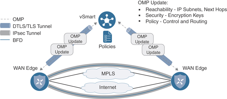
Figure 2-7 Cisco Control Plane and Data Plane Overview
The vSmart operates similarly to a BGP route reflector in iBGP. The vSmart receives routing information from each WAN Edge and can apply policies before advertising this information back out to other WAN Edges. vSmart is also where different topologies are defined per VPN. The control policy is defined in the management plane, the management plane then distributes the policy, and vSmart applies the policy to the fabric. In this example, topology modification is achieved by manipulating what routes get distributed and how the data plane is built between WAN Edges.
The control plane is also responsible for encryption of the fabric. In more legacy WAN technologies, securing the network required a considerable amount of processing power, as each device would compute its own encryption keys and distribute these keys to peers using a protocol such as ISAKMP/IKE. This is usually referred to as “IPsec Phase 1” in legacy nomenclature and is covered in more detail in IETF draft draft-carrel-ipsecme-controller-ike-00. In Cisco SD-WAN, key exchange and distribution have been moved to the vSmart. Each WAN Edge will compute its own keys per transport and distribute these to the vSmart. The vSmart will then distribute them to each WAN Edge, depending on defined policy. In addition, the vSmart is also responsible for rekeying of the IPsec Security Associations (SA) when they expire. By moving key exchange to a centralized location, we achieve greater scale as each WAN Edge doesn’t need to handle key negotiation or distribution. Review Figure 2-7 for an overview of how the control and data planes are built. Chapter 3, “Control Plane and Data Plane Operations,” will also cover this in more detail.
If there is a situation where control connectivity was established but, due to an outage, has been lost, then data plane connectivity will continue to flow. By default, WAN Edges will continue forwarding data plane traffic in the absence of control plane connectivity for 12 hours, utilizing the last-known state of the routing table, though this is configurable, depending on your requirements. When control plane connectivity is reestablished, WAN Edges will be updated with any policy changes that were made during the outage. When the control connection is restored, the route table is flushed and the newly received route table is installed. This will cause a brief outage to the data plane when this occurs.
For redundancy, best practice dictates that you have at least two vSmarts geographically dispersed. vSmarts should have an identical policy configuration to ensure network stability. If these configurations aren’t identical, you risk having suboptimal routing and potential blackholing of traffic. vSmarts will maintain a full mesh of OMP sessions among themselves and exchange control and routing information, though each vSmart will operate autonomously (that is, there is no database synchronized between the two). Figure 2-8 shows how OMP is established between numerous vSmart controllers. It is with this full mesh that the vSmart controllers stay synchronized. If there are more than two vSmarts in the network, control connections from the WAN Edges will be load balanced. If a vSmart goes down, these control connections will get rebalanced across the remaining vSmarts.
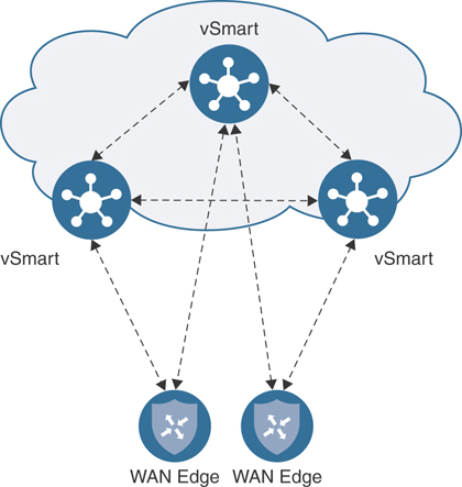
Figure 2-8 OMP Session Establishment
Orchestration Plane
The final, and probably the most important, component in the Cisco SD-WAN solution is the vBond. This component is so important because it provides initial authentication for participation on the fabric and acts as the glue that discovers and brings all other components together. Multiple vBond servers can be deployed to achieve high availability. Though a WAN Edge can point to only a single vBond, it is recommended to have the WAN Edge use DNS and have a single A record point to all vBond IPs. When the WAN Edge tries to resolve the DNS record for the vBond, it will receive each IP address and try to connect to each one sequentially until a successful control connection is made.
When a WAN Edge first joins the overlay, the only thing it knows about is the vBond. It receives this information via one of four methods:
Plug and Play
Zero Touch Provisioning
Bootstrap configuration
Manual configuration
The WAN Edge will attempt to build a temporary connection to the vBond over each transport. Once the control plane connectivity is up to vSmart and vManage, the connection to the vBond will be torn down. At the time that the WAN Edge connects to the vBond, it goes through an authentication process. Each component authenticates each other and, if successful, a Datagram Transport Layer Security (DTLS) tunnel is established. The vBond then distributes the connectivity information for the vSmart and vManage to the WAN Edge. This is why the vBond is essentially referred to as the glue of the network, as it tells all the components about each other. This process will be discussed in more detail in Chapters 3 and 4.
One remaining functionality that the vBond provides is network address translation (NAT) traversal. By default, the vBond operates as a STUN Server (RFC 5389). The WAN Edge operates as a STUN client. What this means is that the vBond can detect when WAN Edges are behind a NAT device such as a firewall. When the WAN Edge goes to establish its DTLS tunnel, the interface IP it knows about will be written into the outer IP header and noted within a payload of the message. When the vBond receives this information, it performs a XOR operation comparing the two values. If the two values are different, it can be inferred that NAT is in the transit path of the WAN Edge (since the outer IP header was changed to a NAT’d IP address and no longer matches the IP address noted in the payload of the packet). The vBond will communicate this back to the WAN Edge, and the WAN Edge can communicate this information to the rest of the overlay components—ultimately allowing data plane connectivity to be established through a NAT device. There are, however, some scenarios where this won’t work, such as with symmetric NAT. This will be discussed in more detail in Chapters 3 and 4. Figure 2-9 explains how STUN is utilized to detect when a WAN Edge or other control plane component is behind a NAT.

Figure 2-9 STUN NAT Detection Method
When you’re deploying a vBond, special consideration must be made around IP connectivity. The vBond must be publicly addressable, though this could be via 1:1 static NAT. The vBond is the only component that must be set up this way. Other components like vManage and vSmart can be behind port address translation (PAT) as long as they have connectivity to the vBond. The control plane and management plane use the same NAT discovery method of STUN as the WAN Edge.
Multi-Tenancy Options
The Cisco SD-WAN solution supports multiple modes of segmentation in the control, data, management, and orchestration planes. Referencing Figure 2-10, the first mode is dedicated tenancy. In this mode, each tenant has dedicated components and the data plane is segmented as well. The second option is VPN tenancy. This mode segments only the data plane of the VPN topology and allows you to define read-only users who can view and monitor their VPN within vManage. VPN tenancy still shares the same SD-WAN components, however. The third option is enterprise tenancy. With this mode, the orchestration and management planes are operating in multi-tenancy mode, but the control plane requires dedicated, per-tenant appliances. Because the control plane is dedicated, it can be deployed as a container or nested virtual machine to decrease scalability concerns.
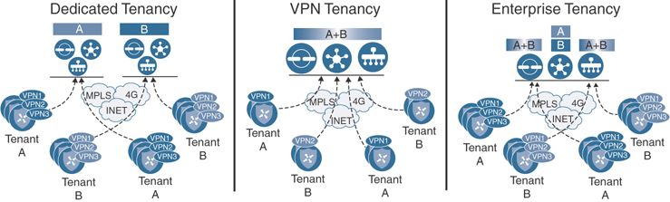
Figure 2-10 Cisco SD-WAN Multi-Tenancy Options
Deployment Options
With the Cisco SD-WAN solution, multiple controller deployment options are supported. The most common deployment utilizes the Cisco Cloud. With Cisco Cloud, Cisco builds all the SD-WAN components that you have been introduced to in this chapter. This greatly simplifies the deployment, allowing the network administrator to focus on configuration and policy administration of the Cisco SD-WAN fabric. Cisco will work with the business to collect the requirements needed to support their use cases and deployment—such as if you have requirements to have controller redundancy globally. In such a case, Cisco will work to deploy disparate controllers.
If the business has a requirement (due to regulatory or business compliance) that necessitates the Cisco SD-WAN controllers be deployed in a different cloud besides the Cisco-managed cloud, then private cloud is the deployment method you would most likely select. Currently supported private clouds are Amazon AWS and Microsoft Azure. When deploying in a private cloud, ensure you have the necessary TCP and UDP ports open for control plane connectivity and that vBond, in particular, has a public IP address or is behind a static 1:1 NAT.
The last deployment option is an on-premises deployment. If business requirements dictate that the Cisco SD-WAN controllers are deployed in a more traditional data center, then an on-premises deployment is what you should review. On-premises deployments will have specific requirements around CPU, memory, and storage in addition to the previously mentioned specific network requirements. On-premises may also be the type of deployment selected when deploying for testing and proof of concept. Chapter 13, “Provisioning Cisco SD-WAN Controllers in a Private Cloud,” covers deploying on-premises controllers in much more detail.
Summary
This chapter introduced the components that make up the Cisco SD-WAN solution. The data plane was discussed, wherein user traffic will be routed and forwarded across the WAN. The data plane is similar to routers that would be deployed in a traditional WAN, though in Cisco SD-WAN, these are referred to as WAN Edges. vManage was also introduced as the management plane. The management plane is where all Day 0, Day 1, and Day N functions will be performed, including WAN Edge configuration, routing and control policies, troubleshooting, and monitoring. The next component that was introduced was vSmart. vSmart is the brain of the Cisco SD-WAN fabric and is responsible for calculating and deploying all control and data policies as well as handling the distribution of encryption keys for data plane connectivity. The last component introduced was the vBond. vBond makes up the orchestration plane and is responsible for authenticating components on the fabric in addition to distributing control and management plane information to the WAN Edges. The vBond is the component that aids in discovery of the fabric for all other components (such as when devices are behind NAT). The final topic discussed was the deployment options. The most common deployment method is via Cisco Cloud, but there are two other options to consider: private cloud and on-premises. By supporting all three deployment options, the Cisco SD-WAN solution can support all business requirements.
Review All Key Topics
Review the most important topics in the chapter, noted with the Key Topic icon in the outer margin of the page. Table 2-2 lists these key topics and the page numbers on which each is found.
Table 2-2 Key Topics
Key Topic Element |
Description |
Page |
|---|---|---|
Cisco SD-WAN Distributed Architecture |
26 |
|
Section |
Data Plane The data plane is where user traffic traverses. Data plane traffic is influenced by the control plane. |
27 |
Cisco SD-WAN Supported Platforms |
30 |
|
Section |
Management Plane How vManage is utilized to manage the SD-WAN fabric from Day 0, Day 1, and Day N. |
32 |
Section |
Control Plane Overview of how the SD-WAN control plane operates. |
34 |
Section |
Orchestration Plane How vBond brings the fabric together and authenticates all the components. |
36 |
Key Terms
Define the following key terms from this chapter, and check your answers in the glossary:
Chapter Review Questions
1. What are the three controllers that make up the Cisco SD-WAN solution?
vSmart
vBond
WAN Edge
vManage
vController
2. How does the Cisco SD-WAN architecture differ from traditional WAN technologies? (Choose three.)
Single pane of glass
Increased scale with centralized control plane
Reduced uptime in branch locations
Topology dependence
Distributed architecture
3. What are the three functions of vManage in the SD-WAN solution?
Troubleshooting
Configuration
Redistribution
Loop prevention
Monitoring
4. WAN Edges provide data plane encryption via IPsec.
True
False
5. What traditional networking concept does vSmart closely relate to?
BGP route reflector
Router
Switch
Hub
6. What functions does the vBond provide in the SD-WAN environment? (Choose two.)
Authentication and whitelisting of the SD-WAN components
NAT detection and traversal
Pushing configuration to WAN Edges
Software upgrades
7. The Cisco SD-WAN solution supports multi-tenancy.
True
False
8. Which routing protocols are supported on the service side of the Cisco SD-WAN solution? (Choose three.)
EIGRP
OSPF
RIP
OMP
BGP
9. What three attributes are measured with BFD?
Delay
Loss
Jitter
Out-of-order packets
10. The Cisco SD-WAN solution is able to provide segmentation and different topologies per VRF.
True
False
References
T. Worster, Y. Rekhter, and E. Rosen, Ed. RFC 4023, “Encapsulating MPLS in IP or Generic Routing Encapsulation (GRE),” Network Working Group, https://tools.ietf.org/html/rfc4023, March 2005
D. Carrel and B. Weis. IETF Draft, “IPsec Key Exchange Using a Controller,” IETF, https://tools.ietf.org/html/draft-carrel-ipsecme-controller-ike-00, January 2018
J. Rosenberg, R. Mahy, P. Matthews, and D. Wing. RFC 5389, “Session Traversal Utilities for NAT (STUN),” Network Working Group, https://tools.ietf.org/html/rfc5389, October 2008