The Terrain class is where we will do the most of our heavy lifting. This is the class that will create the hills in the game. When I say create, I mean give them that beautiful, colorful, materialistic appearance that you saw in the screenshot. In addition to that, this class will also generate the smooth curve of the hill and also create its physics body. Finally, it will be responsible for scrolling and scaling itself with respect to the penguin's position.
The Terrain class will inherit from CCNode. We will define this class in parts, starting with the most exciting part of all, the texture generation. We will then write code to generate the hills and the Box2D body. So, sharpen your pencils and smoothen your paintbrushes. Programmatic texture generation, here we come!
We will implement our Terrain class in the following steps:
In Chapter 4, Back to the Drawing Board, we did some primitive drawing with Inverse Universe using the CCDrawNode class. However, that was much different in comparison to what we will be doing here. The highlight of this chapter will be using a few OpenGL commands to render some things on our own. It is imperative to have some basic knowledge of OpenGL to make the most of this chapter, so I strongly advise you to consult Google to cover the basics before diving into the code for this chapter. Alternatively, you could just use the OpenGL website as a starting point:
https://www.opengl.org/sdk/docs/man4/
If you were as curious as I was, you must have Ctrl and click or used F12 on the CCDrawNode class to view what it actually does to draw primitives. If you didn't, it actually calculates the vertices for each shape and draws them each frame using OpenGL commands. That is exactly what we will do, but we will save all of that drawing into a texture. Confused? Well, everything will seem vibrant and colorful on the other side of the GenerateStripedSprite function (it's difficult to type and pronounce) from the Terrain.cpp file:
CCSprite* Terrain::GenerateStripedSprite(EStripeType stripe_type,
int num_stripes)
{
// create a texture that we can draw into
CCRenderTexture* render_texture = CCRenderTexture::create(
STRIPE_TEXTURE_SIZE, STRIPE_TEXTURE_SIZE);
// begin with pure black
render_texture->beginWithClear(0.0f, 0.0f, 0.0f, 0.0f);
RenderStripes(stripe_type, num_stripes);
RenderGradient();
RenderHighlight();
RenderTopBorder();
RenderNoise();
render_texture->end();
// create a sprite out of the rendered texture & return it
return CCSprite::createWithTexture(
render_texture->getSprite()->getTexture());
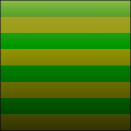
}Before we define this function with the tongue-twisting name, I want to show you the CCSprite that it returns to us:

The preceding image has a set of colored stripes, plus a gradient causing the image to be light at the top and dark at the bottom. That is then followed by a sort of yellow shine on the top of the image plus a very fine border across the top edge. Finally, a noise texture is applied to the image so it has a material appearance instead of looking completely flat.
Now, the first thing we do is create a new CCRenderTexture object, passing in the desired width and height of the resultant texture. We follow that up by calling the beginWithClear function on our new render_texture object. This sets up the renderer so that all subsequent OpenGL commands will draw into the texture instead of the frame buffer and consequently the screen. In addition to that, it also clears the texture and fills it with a color, as indicated by the parameters passed in.
After calling beginWithClear, every subsequent OpenGL command will affect the texture, and thus, we must call the end function of the CCRenderTexture class. This will stop the CCRenderTexture class from grabbing any further OpenGL commands. In essence, all that we want to draw into our custom texture will have to be drawn between these two functions: begin/beginWithClear and end. We will discuss each of the five functions you see in the following sections and I will show you the output after each step.
In our texture, first we draw the stripes that will give our game its signature look. To do that, we define a function named RenderStripes that accepts the type of stripe and the number of stripes. The type of stripe is described by an enum named EStripeType, which you will find in the GameGlobals.cpp file. This is quite a large function with a lot of new things to learn. So, we'll discuss it part by part instead of all at once:
void Terrain::RenderStripes(EStripeType stripe_type, int num_stripes)
{
  // allocate memory for the position & colour arrays
  ccVertex2F* vertices = (ccVertex2F*)malloc(sizeof(ccVertex2F) * num_stripes * 6);
  ccColor4F* colors = (ccColor4F*)malloc(sizeof(ccColor4F) * num_stripes * 6);

  // initialise variables
  int num_vertices = 0;
  float x1 = 0.0f, x2 = 0.0f, y1 = 0.0f, y2 = 0.0f, dx = 0.0f, dy = 0.0f;

  // select between two colours or many colours
  bool two_colors = (CCRANDOM_MINUS1_1() > 0);
  ccColor4F color1 = GameGlobals::GetRandomColor();
  ccColor4F color2 = GameGlobals::GetRandomColor();
  ccColor4F c;
We begin by allocating memory for our two arrays, vertices and colors, which are of the type ccVertex2F and ccColor4F, respectively. These arrays will hold the position and color data at each vertex for each stripe. We then have a counter for the total number of vertices generated followed by variables to represent the coordinates of each vertex composing the stripe. The EStripeType enum that is passed as an argument to this function describes three types of stripes, that is, horizontal, diagonal (top-left to bottom-right), and diagonal (bottom-left to top-right). We will go over the code for each of them separately, starting with the horizontal stripes:
if(stripe_type == E_STRIPE_HORIZONTAL)
{
// initialise variables for the horizontal stripe
dx = 0;
dy = (float)STRIPE_TEXTURE_SIZE / (float)num_stripes;
x1 = 0;
y1 = 0;
x2 = STRIPE_TEXTURE_SIZE;
y2 = 0;
// generate position & colour for each vertex of the stripe
for (int i = 0; i < num_stripes; ++ i)
{
c = two_colors ? (i%2 ? color1 : color2) :
GameGlobals::GetRandomColor();
colors[num_vertices] = c;
vertices[num_vertices ++] = vertex2(x1, y1);
colors[num_vertices] = c;
vertices[num_vertices ++] = vertex2(x2, y2);
colors[num_vertices] = c;
vertices[num_vertices ++] = vertex2(x1, y1 + dy);
colors[num_vertices] = c;
vertices[num_vertices ++] = vertices[num_vertices - 2];
colors[num_vertices] = c;
vertices[num_vertices ++] = vertices[num_vertices - 2];
colors[num_vertices] = c;
vertices[num_vertices ++] = vertex2(x2, y2 + dy);
y1 += dy;
y2 += dy;
}
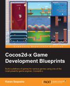
}Before we discuss the code, here is a visual representation of what this code block results in:
As you can see in the preceding figure, each stripe is nothing but a rectangle described by four vertices (v0, v1, v2, v3). However, we will draw this rectangle as two separate triangles. The two triangles will be described by vertices (v0, v1, v2) and (v1, v2, v3) respectively. That makes a total of six vertices for each stripe and that is why we multiply num_stripes by the number six while allocating memory to vertices and colors.
At the top of the block, we have defined the delta movement for both x and y coordinates into variables dx and dy respectively, followed by the initial values for the first stripe. We then write a loop that calculates six vertices for each stripe. In the loop, we either select from the two colors (as in the preceding figure) or we select a random color for each stripe. What follows is code to describe the six vertices (v0, v1, v2) and (v1, v2, v3) that will complete a single stripe. The loop terminates by incrementing y1 and y2 by dy to calculate vertices for the next stripe.
Now, let's look at code that generates vertices for the diagonal stripes:
else
{
// initialise variables based on type of stripe
dx = (float)STRIPE_TEXTURE_SIZE * 2 / (float)num_stripes;
dy = 0;
x1 = -STRIPE_TEXTURE_SIZE;
y1 = (stripe_type == E_STRIPE_SLOPE_DOWN) ? 0 :
STRIPE_TEXTURE_SIZE;
x2 = 0;
y2 = (stripe_type == E_STRIPE_SLOPE_DOWN) ?
STRIPE_TEXTURE_SIZE : 0;
// generate position & colours for two stripes at a time
for (int i = 0; i < num_stripes / 2; ++ i)
{
c = two_colors ? (i%2 ? color1 : color2) :
GameGlobals::GetRandomColor();
for(int j = 0; j < 2; ++ j)
{
colors[num_vertices] = c;
vertices[num_vertices ++] = vertex2(x1 + j *
STRIPE_TEXTURE_SIZE, y1);
colors[num_vertices] = c;
vertices[num_vertices ++] = vertex2(x1 + j *
STRIPE_TEXTURE_SIZE + dx, y1);
colors[num_vertices] = c;
vertices[num_vertices ++] = vertex2(x2 + j *
STRIPE_TEXTURE_SIZE, y2);
colors[num_vertices] = c;
vertices[num_vertices ++] = vertices[num_vertices - 2];
colors[num_vertices] = c;
vertices[num_vertices ++] = vertices[num_vertices - 2];
colors[num_vertices] = c;
vertices[num_vertices ++] = vertex2(x2 + j *
STRIPE_TEXTURE_SIZE + dx, y2);
}
x1 += dx;
x2 += dx;
}
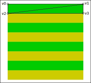
}Before we discuss the code, here is a visual representation of what this code block results in when the stripe type is E_STRIPE_SLOPE_DOWN:
The logic we'll use to draw diagonal stripes will be quite different as compared to horizontal stripes. As you can see in the preceding figure, vertex v0 of the first stripe starts far out to the left of the actual texture (indicated by the black outlined square in the center). Thus, we initialize x1 with a value equal to -STRIPE_TEXTURE_SIZE and x2 with 0.
The variables y1 and y2 are defined based on whether our stripe will be top-left to bottom-right (E_STRIPE_SLOPE_DOWN) or bottom-left to top-right (E_STRIPE_SLOPE_UP). We then define a nested structure of loops that draws two stripes at a time. So, the vertices generated within the inner for loop will be for stripe-1 (green) and stripe-3 (green), then stripe-2 (yellow) and stripe-4 (yellow), and so on.
Now that we've calculated vertices for the various types of stripes, it is time to actually make the OpenGL calls that will do the rendering for us. So, let's take a look at the last part of the RenderStripes function:
// we're dealing with position & colour data here
setShaderProgram(CCShaderCache::sharedShaderCache()->programForKey(kCCShader_PositionColor));
CC_NODE_DRAW_SETUP();

// enable position & colour attributes
ccGLEnableVertexAttribs(kCCVertexAttribFlag_Position | kCCVertexAttribFlag_Color);
// pass position & colour data
glVertexAttribPointer(kCCVertexAttrib_Position, 2, GL_FLOAT, GL_FALSE, 0, vertices);
glVertexAttribPointer(kCCVertexAttrib_Color, 4, GL_FLOAT, GL_TRUE, 0, colors);
// set the blend function
glBlendFunc(GL_ONE, GL_ONE_MINUS_SRC_ALPHA);
// draw it...GL_TRIANGLES style!
glDrawArrays(GL_TRIANGLES, 0, (GLsizei)num_vertices);

// free what we allocated on top
free(vertices);
free(colors);
We kick off the rendering by setting the shader program for this node. Shaders are a huge aspect of graphics programming, but unfortunately they're way out of the scope of this book. For now, all you need to know is that shaders are simply programs that run on the GPU. Cocos2d-x comes with a bunch of default shaders that are loaded into the CCShaderCache class. You can also create and cache your own shaders into this class.
Here, we're rendering colored stripes and we're dealing only with the position and color for each stripe, which is why we select the kCCShader_PositionColor type of shader. You can find all the default shaders at the following path:
cocos2d-x-2.2.5cocos2dxshaders
We then use a convenience macro CC_NODE_DRAW_SETUP() that sets up the GL server state and links the shader program we set. We then call the ccGLEnableVertexAttribs function, passing in the flags kCCVertexAttribFlag_Position and kCCVertexAttribFlag_Color. This function informs OpenGL which attributes of the vertex will be used while rendering. The ccGLEnableVertexAttribs function has OpenGL function glEnableVertexAttribArray at its heart.
Note
You can find more information on glEnableVertexAttribArray at https://www.khronos.org/opengles/sdk/docs/man/xhtml/glEnableVertexAttribArray.xml.
Next, we make two calls to the glVertexAttribPointer function, one each for the position and color attributes that we just enabled. This function basically tells OpenGL how to interpret the data that we're passing into this function via the arrays vertices and colors.
Note
You can find more information on glVertexAttribPointer at https://www.khronos.org/opengles/sdk/docs/man/xhtml/glVertexAttribPointer.xml.
We must now set the blend mode by calling glBlendFunc, which basically specifies how the incoming values (the colored stripes we're about to render) will affect the existing values (so far, we have nothing, though). We pass in GL_ONE as the source factor, which means that all the existing values will be carried forward, and we pass in GL_ONE_MINUS_SRC_ALPHA as the destination factor, which means that the incoming values will be rendered wherever there is transparency in the existing values.
Note
You can use this incredible visual tool to help you understand blend functions (http://www.andersriggelsen.dk/glblendfunc.php).
Finally, we call the glDrawArrays function that renders the vertex data that we just passed through glVertexAttribPointer.
The first parameter to glDrawArrays, GL_TRIANGLES, tells OpenGL that it should use all three vertices to draw a single triangle. The second parameter is the starting index from within the array where the vertices will be read. The last parameter is simply the number of vertices that we want rendered.
Note
You can find more information on the glDrawArrays function at https://www.khronos.org/opengles/sdk/docs/man/xhtml/glDrawArrays.xml.
Now that we're done with the rendering, we must free the two arrays that we allocated memory to, at the start of the function. This winds up the RenderStripe function.
Now that we've drawn our stripes, we can go ahead and beautify the texture with a gradient. Remember that this texture will be applied to a landscape of mountains and we need to create an illusion of a shadow. Thus, our gradient will be light at the top and get darker towards the bottom. Let's take a look at the RenderGradient function from Terrain.cpp:
void Terrain::RenderGradient()
{
// declare arrays for position & colour data
ccVertex2F vertices[4];
ccColor4F colors[4];
// gradient will be light on top & dark at the bottom
vertices[0] = vertex2(0, 0);
vertices[1] = vertex2(STRIPE_TEXTURE_SIZE, 0);
vertices[2] = vertex2(0, STRIPE_TEXTURE_SIZE);
vertices[3] = vertex2(STRIPE_TEXTURE_SIZE, STRIPE_TEXTURE_SIZE);
colors[0] = ccc4f(0.0f, 0.0f, 0.0f, 0.0f);
colors[1] = ccc4f(0.0f, 0.0f, 0.0f, 0.0f);
colors[2] = ccc4f(0.0f, 0.0f, 0.0f, 0.75f);
colors[3] = ccc4f(0.0f, 0.0f, 0.0f, 0.75f);
// we're dealing with position & colour data here
setShaderProgram(CCShaderCache::sharedShaderCache()->programForKey(
kCCShader_PositionColor));
CC_NODE_DRAW_SETUP();
// enable position & colour attributes
ccGLEnableVertexAttribs(kCCVertexAttribFlag_Position |
kCCVertexAttribFlag_Color);
// pass position & colour data
glVertexAttribPointer(kCCVertexAttrib_Position, 2,
GL_FLOAT, GL_FALSE, 0, vertices);
glVertexAttribPointer(kCCVertexAttrib_Color, 4,
GL_FLOAT, GL_FALSE, 0, colors);
// draw it...GL_TRIANGLE_STRIP style!
glDrawArrays(GL_TRIANGLE_STRIP, 0, 4);
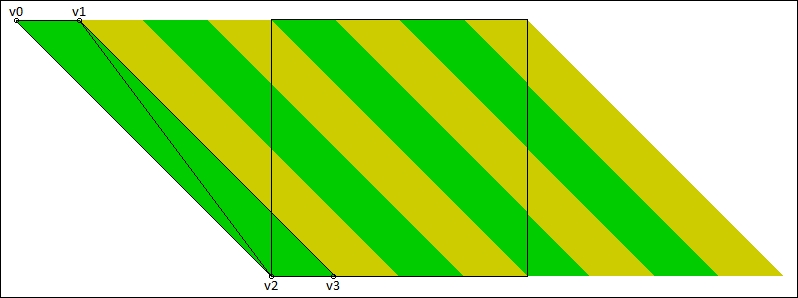
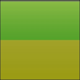
}At the start of the function, we define two arrays to hold the position and color information for the gradient. We then fill in the positions as the top-left, top-right, bottom-left, and bottom-right corners into the vertices array. This is followed by filling in the color data, which is a completely transparent black color at the top with 75 percent opacity at the bottom.
Just by doing that, we have created a gradient, as OpenGL will automatically interpolate the alpha values between 0 and 75 percent when it runs the position-color shader. I am sure that you noticed how the arrays have only four elements instead of the six we had for the stripes. This is because we use a different drawing mode, named GL_TRIANGLE_STRIP, this time. GL_TRIANGLE_STRIP informs OpenGL that every triangle it draws will have the first two vertices same as the last two vertices of the previous triangle.
Thus, at the time of rendering, the gradient will be composed of two triangles having vertices {(0, 0), (STRIPE_TEXTURE_SIZE, 0), (0, STRIPE_TEXTURE_SIZE)} and {(STRIPE_TEXTURE_SIZE, 0), (0, STRIPE_TEXTURE_SIZE), (STRIPE_TEXTURE_SIZE, STRIPE_TEXTURE_SIZE)}, respectively.
I'm sure you're wondering why we didn't use GL_TRIANGLE_STRIP while rendering the stripes given that we could have saved two vertices for each stripe. Since GL_TRIANGLE_STRIP causes triangles to share their vertices, all the triangles it draws must be connected or adjacent to each other. If you remember, while calculating vertices for the diagonal stripes, we were drawing two stripes that were apart from each other. That's the reason why we had to use GL_TRIANGLES. So far, this is what our texture looks like:
We will add some more realism to our texture by giving it some shine at the top to resemble sunlight falling on the surface of the hill. The RenderHighlight function from the Terrain.cpp file will do exactly that:
void Terrain::RenderHighlight()
{
  // declare arrays for position & colour data
  ccVertex2F vertices[4];
  ccColor4F colors[4];

  // highlight will be yellowish on top & nothing at the bottom
  vertices[0] = vertex2(0, 0);
  vertices[1] = vertex2(STRIPE_TEXTURE_SIZE, 0);
  vertices[2] = vertex2(0, STRIPE_TEXTURE_SIZE/3);
  vertices[3] = vertex2(STRIPE_TEXTURE_SIZE, STRIPE_TEXTURE_SIZE/3);
  colors[0] = ccc4f(1.0f, 1.0f, 0.5f, 0.4f);
  colors[1] = ccc4f(1.0f, 1.0f, 0.5f, 0.4f);
  colors[2] = ccc4f(1.0f, 1.0f, 0.5f, 0.0f);
  colors[3] = ccc4f(1.0f, 1.0f, 0.5f, 0.0f);

  // we're dealing with position & colour data here
  setShaderProgram(CCShaderCache::sharedShaderCache()->programForKey(
    kCCShader_PositionColor));
  CC_NODE_DRAW_SETUP();

  // enable position & colour attributes
  ccGLEnableVertexAttribs(kCCVertexAttribFlag_Position |
    kCCVertexAttribFlag_Color);
  // pass position & colour data
  glVertexAttribPointer(kCCVertexAttrib_Position, 2,
    GL_FLOAT, GL_FALSE, 0, vertices);
  glVertexAttribPointer(kCCVertexAttrib_Color, 4,
    GL_FLOAT, GL_FALSE, 0, colors);
  // set the blend function
  glBlendFunc(GL_SRC_ALPHA, GL_ONE_MINUS_SRC_ALPHA);
  // draw it...GL_TRIANGLE_STRIP style!
  glDrawArrays(GL_TRIANGLE_STRIP, 0, 4);
}
Much of the code here is similar to the function RenderGradient, except that the highlight will be applied only to the upper one-third of the texture and the color will be a shade of yellow. Another difference here is the presence of the function glBlendFunc. This is what our texture looks like with some highlight applied:
We now add a thin border to the top of the texture, which when applied to the hills will provide an outline and represent the surface of the hill. The RenderTopBorder function from Terrain.cpp will take care of that. This function bears resemblance to the last two functions, so we shall skip discussing it in detail. The function simply renders a 3-pixel thick gray rectangle at the top of the texture. I'm sure you'll understand this function when you look at it in the source bundle.
Moving on, this is how the texture will look after this function has returned. I've taken the liberty of zooming in so that you can see the border clearly:
We've added a lot of effects to the texture, but it still lacks a material feel and it appears flat. So, we'll add some noise to the texture in the RenderNoise function from the Terrain.cpp file:
void Terrain::RenderNoise()
{
  // create a sprite with readymade noise
  CCSprite* noise = CCSprite::create("noise1.png");
  // set the proper blend function
  ccBlendFunc blend_func;
  blend_func.src = GL_DST_COLOR;
  blend_func.dst = GL_ZERO;
  noise->setBlendFunc(blend_func);
  // position the sprite at the centre of the texture
  noise->setPosition(ccp(STRIPE_TEXTURE_SIZE/2,
    STRIPE_TEXTURE_SIZE/2));
  // call visit to render the sprite...twice gives added contrast
  noise->visit();
  noise->visit();
}
I'm sure you were expecting more than that! Well, every CCSprite class defines the similar set of OpenGL commands in its draw function like the ones we just wrote. So, all we really need to do here is create a CCSprite with a pre-rendered noise texture and call its visit function.
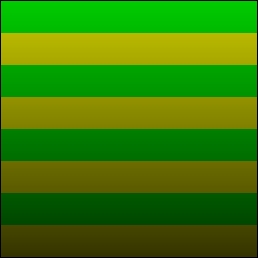
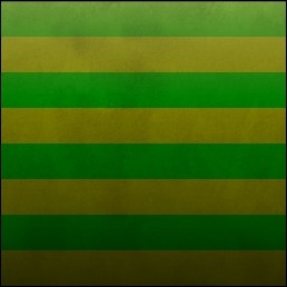
With the RenderNoise function, we complete the generation of a multicolor, realistic, striped texture. With the complicated rendering behind our back, we can now move forward to the creation of the hills. Before that, this is what the texture looks like after the RenderNoise function has returned:
The shape of the hills in Penguins Can Fly won't be ultra-realistic, but they should be diverse enough to offer the player an engaging and exciting experience. We will split the algorithm to generate the structure of the hills into two parts: generation of key points and generation of smooth curves. The key points will basically be the peak and bottom points of the hill. After these points are generated, we will have a staircase structure with flat lines between the peak and bottom. We will then write code to interpolate a smooth curve between these key points.
The hill key points will be nothing but the highest and lowest points on the surface of the hill. We must ensure that a peak is followed by a bottom, and vice versa, to ensure smooth continuity. Also, we would like to control the amount by which a peak rises and the amount a bottom falls. This would enable us to make the terrain easier or more difficult. Let's now take a look at the GenerateHillKeyPoints function from the Terrain.cpp file:
void Terrain::GenerateHillKeyPoints(float start_x)
{
  // initialise variables
  num_hill_key_points_ = 0;

  float x, y, dx, dy, ny;

  // first hill key point will be a bit outside the left edge of the screen
  x = start_x - SCREEN_SIZE.width * 0.25f;
  y = 0;
  hill_key_points_[num_hill_key_points_ ++] = vertex2(x, y);

  // the first peak
  x = start_x;
  y = SCREEN_SIZE.height * 0.4f;
  hill_key_points_[num_hill_key_points_ ++] = vertex2(x, y);
We begin this function by initializing the number of hill key points and variables that will represent the x and y coordinates of each key point. We now initialize the first hill key point as being outside the left edge of the screen and right at the bottom. We then create the first peak at the x coordinate that is passed to this function and at a considerable height from the bottom of the screen. Continuing with the GenerateHillKeyPoints function from the Terrain.cpp file:
  // set the minimum & range quantities
  int min_dx = 160, range_dx = 80;
  int min_dy = 60,  range_dy = 60;
  // +1 - going up, -1 - going  down
  float sign = -1;
  // set the limits
  float max_height = SCREEN_SIZE.height * 0.5f;
  float min_height = SCREEN_SIZE.height * 0.25f;
Now that we've specified how the start of the hill will look, we can write a simple algorithm to generate the rest of the hill. First, we need to define a few parameters for the algorithm. The min_dx and min_dy variables will represent the minimum distance any two hill key points will have between each other, whereas the range_dx and range_dy variables will be used to select a random distance value that will be added to min_dx and min_dy. The sign variable will be toggled between 1 and -1 so that the algorithm generates a peak followed by a bottom followed by a peak and so on. Finally, we define a couple of constraints that prevent the algorithm from generating key points that are too high or too low.
In the GameGlobals.h file, you will find MAX_HILL_KEY_POINTS defined as 100. So, we have 50 peaks and 50 bottoms.
Let's look at the following code:
// first set of points
while (num_hill_key_points_ < MAX_HILL_KEY_POINTS - 15)
{
  dx = CCRANDOM_0_1() * range_dx + min_dx;
  x += dx;
  dy = CCRANDOM_0_1() * range_dy + min_dy;
  ny = y + dy * sign;
  if(ny > max_height) ny = max_height;
  if(ny < min_height) ny = min_height;
  y = ny;
  sign *= -1;
  hill_key_points_[num_hill_key_points_++] = vertex2(x, y);
}
In the preceding code, we define the majority of the hill key points. The reason we don't define them all in a single loop is because we want to create a kind of ramp at the end of the hill for the penguin to launch off. As you read earlier, we use range_dx/dy in combination with min_dx/dy to generate a delta into dx and dy. We then multiply the y coordinate with sign and restrict it within the appropriate constraints. Finally, we toggle sign by negating it and save the new hill point as a ccVertex2F object in the hill_key_points_ array.
Let's now look at the last part of the function that takes care of generating the ramp-like structure towards the end of the hill. This loop will gradually lower the peak and bottom hill key points so that the last peak is high enough to act like a ramp for the penguin to take off.
Let's look at the following code:
// points that will go lower and lower
  min_height = SCREEN_SIZE.height * 0.1f;
  while (num_hill_key_points_ < MAX_HILL_KEY_POINTS - 2)
  {
    dx = CCRANDOM_0_1() * range_dx + min_dx;
    x += dx;
    dy = CCRANDOM_0_1() * range_dy + min_dy;
    ny = ( (y + dy * sign) < hill_key_points_[
      num_hill_key_points_ - 2].y ) ? (y + dy * sign) :
      (y + dy * sign * 0.5f);
    if(ny < min_height) ny = min_height;
    y = ny;
    sign *= -1;
    hill_key_points_[num_hill_key_points_++] = vertex2(x, y);
  }

  // finally a nice upward slope...the ramp to launch the penguin
  x += min_dx + range_dx * 3;
  y += min_dy + range_dy * 1.5f;
  hill_key_points_[num_hill_key_points_++] = vertex2(x, y);

  // last point will be way down below
  x += min_dx + range_dx * 1.5f;
  y = 0;
  hill_key_points_[num_hill_key_points_++] = vertex2(x, y);

  // initialise left most & right most key points
  from_key_point_ = 0;
  to_key_point_ = 0;
}
We start the loop by lowering min_height to SCREEN_SIZE.height * 0.1f from SCREEN_SIZE.height * 0.25f. This while loop is similar to the previous one except that it possesses a condition that ensures each peak is lower in elevation than the previous peak. The loop still doesn't create the ramp for us though. That is why we add the last two hill key points by ourselves.
Notice how the first hill key point that we add manually has the range multiplied so as to increase the distance between this key point and the previous, thereby creating a ramp. We then finish the hill structure off by creating the last key point at the bottom of the screen. We will discuss the from_key_point_ and to_key_point_ variables in a bit. For now, I have a screenshot of the hill key points that are generated by this function, so you know exactly what we have achieved:
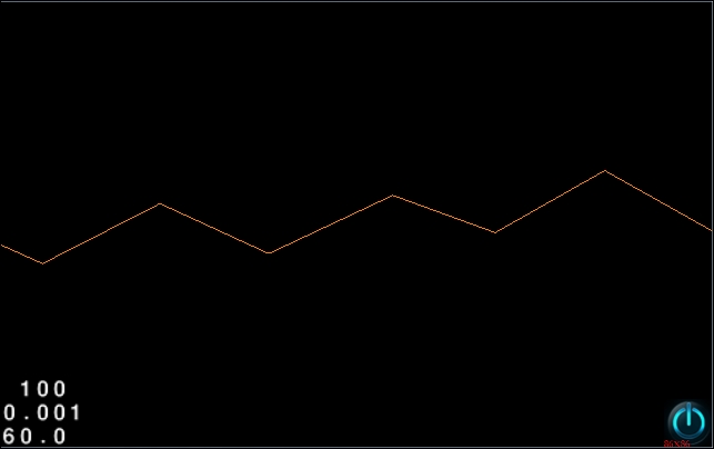
In the preceding screenshot, you can tell that we have the key points correct. But this is not gameplay material. In order to make things realistic and fun, we will need to give the hills a smooth, curved surface over which the penguin can easily slide and take off too. We will make use of a simple cosine curve to achieve a neatly interpolated curve between two hill key points. If you're rusty on your trigonometry, this is what a cosine curve looks like:
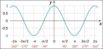
So, we want the y coordinates of the slope to be a factor of a cosine curve as it passes from 0 to pi. All this happens in the GenerateBorderVertices function of Terrain.cpp:
void Terrain::GenerateBorderVertices()
{
  // initialise variables
  num_border_vertices_ = 0;

  ccVertex2F p0, p1, pt0, pt1;
  p0 = hill_key_points_[0];

  for (int i = 1; i < num_hill_key_points_; ++ i)
  {
    p1 = hill_key_points_[i];

    // calculate the number of segments between adjacent key points
    int h_segments = floorf((p1.x - p0.x) / HILL_SEGMENT_WIDTH);
    // calculate delta x
    float dx = (p1.x - p0.x) / h_segments;
    // calculate delta theta
    float da = M_PI / h_segments;
    // calculate x-axis & amplitude for the cosine wave
    float ymid = (p0.y + p1.y) / 2;
    float ampl = (p0.y - p1.y) / 2;
    pt0 = p0;
    border_vertices_[num_border_vertices_++] = pt0;

    // for each segment, calculate x & y coordinate
    for (int j = 1; j < h_segments + 1; ++ j)
    {
      // x coordinate is last coordinate plus delta
      pt1.x = p0.x + j * dx;
      // y coordinate taken from the cosine wave
      pt1.y = ymid + ampl * cosf(da * j);
      border_vertices_[num_border_vertices_ ++] = pt1;
      pt0 = pt1;
    }

    p0 = p1;
  }
}
At the start of the function, we initialize the various variables and counters.
We initialize p0 to point to the first key point in the hill_key_points_ array and start the for loop from 1 instead of 0.
Inside the loop, we initialize p1 and calculate the number of segments between p0 and p1 based on the width of each segment (HILL_SEGMENT_WIDTH value as 15). We must calculate the delta for the x coordinate and for the angle (theta). We then calculate the midpoint of the segment between p0 and p1 in terms of the y coordinate into the ymid variable. This will act as the x axis for our cosine curve. We also define an amplitude that we will multiply by the cosine curve; the larger the amplitude, the greater the distance between the peak and bottom of the cosine curve.
We then run a loop to interpolate from p0 to p1, one segment at a time. Inside the loop, we calculate the vertices of the individual segment that will make up the curve. Notice how we use the cosf function to calculate the y coordinate of the curve. The following screenshot shows what happens when the points generated in the border_vertices_ array are joined:
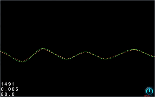
In this screenshot, you can see the hill key points and the smooth curve that is generated around them. At this point, we have a smoothly interpolated surface of the hill. We can now build a Box2D body with the vertices generated in the GenerateBorderVertices function.
The Box2D body of the hill will be static and its fixture will contain a chain shape. Let's take a look at what exactly happens in the CreateBody function of Terrain.cpp:
void Terrain::CreateBody()
{
  // create a body only the first time...after that only
    create fixture
  if(body_ == NULL)
  {
    b2BodyDef bd;
    bd.position.Set(0, 0);
    body_ = world_->CreateBody(&bd);
  }

  // create array for the vertices
  b2Vec2 vertices[MAX_BORDER_VERTICES];
  int num_vertices = 0;
  // loop through border_vertices_, convert screen
    coordinates to physics coordinates
  for (int i = 0; i < num_border_vertices_; ++ i)
  {
    vertices[num_vertices ++].Set(SCREEN_TO_WORLD(
      border_vertices_[i].x), SCREEN_TO_WORLD(border_vertices_[i].y));
  }

  // finish up the last two vertices to form a loop
  vertices[num_vertices ++].Set(SCREEN_TO_WORLD(border_vertices_[
    num_border_vertices_ - 1].x), 0);
  vertices[num_vertices ++].Set(SCREEN_TO_WORLD(
    border_vertices_[0].x), 0);

  // create the chain fixture with above vertices
  b2ChainShape shape;
  shape.CreateChain(vertices, num_vertices);
  body_->CreateFixture(&shape, 0);
}
We begin by creating a static b2Body object into the member variable body_ of class Terrain. We then declare an array of type b2Vec2 named vertices before filling it up with the vertices we just calculated and fed into border_vertices_. Notice the helper macro SCREEN_TO_WORLD converting the coordinates from pixels to meters. Once this is done, we simply create a b2ChainShape object passing in the vertices array along with the number of vertices the chain should have. We wind up this function by creating a new fixture that will glue body_ to the chain shape.
In our Terrain class, we have written code to generate a striped texture, generate vertices for a smooth curved hill, and even created a Box2D body. We still haven't rendered the hill though. We still need to bind the striped texture to the vertices of the curve and render the hill.
Before we write code to render the hills inside the draw function, we need to save the texture we generated by calling the GenerateStripedSprite function. So, let's take a look at a part of the init function from Terrain.cpp:
bool Terrain::init(b2World* world, float start_x)
{
  .
  .
  .
  // select between a type of stripe
  EStripeType stripe_type = (EStripeType)((int)(CCRANDOM_0_1() *
    (E_STRIPE_SLOPE_DOWN + 1)));
  // generate the stiped sprite
  sprite_ = GenerateStripedSprite(stripe_type , 8);
  // retain for use since we won't be adding it
  sprite_->retain();
  // setup the texture to repeat and stick to the edge
  ccTexParams tex_params;
  tex_params.minFilter = GL_LINEAR;
    tex_params.magFilter = GL_LINEAR;
  tex_params.wrapS = GL_REPEAT;
    tex_params.wrapT = GL_CLAMP_TO_EDGE;
  sprite_->getTexture()->setTexParameters(&tex_params);
  .
  .
  .
  .
}
Before we generate a texture, we must choose what type of stripes we want it to have. We then pass this stripe type into the GenerateStripedSprite function. If you remember, the GenerateStripedSprite function returns a pointer to a new CCSprite, which we now save into a member variable of class Terrain named sprite_. Since we won't really be adding the sprite_ to the scene graph, we must retain it.
We also define the texture parameters for this sprite's texture, since we intend on repeating it along the vertices of the hill. Doing this will keep the sprite ready to be bound to the hill's vertices, but it won't actually render anything. So, we must define the draw function that class Terrain will override from CCNode as follows:
void Terrain::draw()
{
  // can't render without a sprite
  if(sprite_ == NULL)
  {
    return;
  }

  CC_NODE_DRAW_SETUP();

  // bind the texture for this node
  ccGLBindTexture2D(sprite_->getTexture()->getName());
  // enable position & colour attributes
  ccGLEnableVertexAttribs(kCCVertexAttribFlag_Position | kCCVertexAttribFlag_TexCoords);
  // pass position & colour data
  glVertexAttribPointer(kCCVertexAttrib_Position, 2, GL_FLOAT, GL_FALSE, 0, hill_vertices_);
  glVertexAttribPointer(kCCVertexAttrib_TexCoords, 2, GL_FLOAT, GL_FALSE, 0, hill_tex_coords_);
  // draw it...GL_TRIANGLE_STRIP style!
  glDrawArrays(GL_TRIANGLE_STRIP, 0, (GLsizei)num_hill_vertices_);
}
We begin by checking whether the stripe texture sprite exists. You should be familiar with the code in this function by now, so I'll only highlight the differences. We call the ccGLBindTexture2D function here and pass in the name of the striped texture stored within sprite_. This is a method from Cocos2d-x that essentially calls the OpenGL command glBindTexture. The glBindTexture function simply binds a texture pointed to by the specified name to the active texture unit, which in this case is the node we're rendering.
Note
You can find more information on glBindTexture at https://www.khronos.org/opengles/sdk/docs/man/xhtml/glBindTexture.xml.
Another difference I'm sure you noticed is the flags we passed into ccGLEnableVertexAttribs. In this case, we're passing in the position and texture coordinates and not colors, so we enable the flags kCCVertexAttribFlag_Position and kCCVertexAttribFlag_TexCoords respectively. We then pass the position data stored inside hill_vertices_ and the texture coordinate data stored inside hill_tex_coords_ to OpenGL before calling glDrawArrays with the GL_TRIANGLE_STRIP draw mode.
But when did we create the arrays hill_vertices_ and hill_tex_coords_? Well, we haven't yet. So, let's look at the ResetVertices function from Terrain.cpp and see how these arrays are filled up. This one is a slightly large function, so we will look at it in parts:
void Terrain::ResetVertices()
{
  // calculate the area of the hill that is currently visible plus a buffer of
    0.125 * screen width
  float left_side = offset_x_ - SCREEN_SIZE.width *
    0.125f / m_fScaleX;
  float right_side = offset_x_ + SCREEN_SIZE.width *
    1.125f / m_fScaleX;

  // loop to calculate the left most key point
  while (hill_key_points_[from_key_point_ + 1].x < left_side)
  {
    from_key_point_ ++;
    if (from_key_point_ > num_hill_key_points_ - 1) {
      from_key_point_ = num_hill_key_points_ - 1;
      break;
    }
  }

  // loop to calculate the right most key point
  while (hill_key_points_[to_key_point_].x < right_side)
  {
    to_key_point_ ++;
    if (to_key_point_ > num_hill_key_points_ - 1) {
      to_key_point_ = num_hill_key_points_ - 1;
      break;
    }
  }
We begin this function by calculating the left and right limits of the hill. These limits are important because we will render only that area of the hill that is contained within these limits, as opposed to the entire hill. The offset_x_ variable that is used in this calculation is nothing but the horizontal distance the hill has moved from its initial position. We must update offset_x_ with respect to the position of the penguin to ensure that the hills scroll but more on that later.
Next, we have two while loops to identify the left-most and right-most hill key points based on left_side and right_side. We store these values into from_key_point_ and to_key_point_ respectively. If you remember, both these variables were initialized to 0 at the end of the GenerateHillKeyPoints function. We can use these two variables to govern how many hill key points will be used in rendering the hill, which is handled in the next part of the ResetVertices function:
// only loop if visible key points have changed
  if (prev_from_key_point_ != from_key_point_ ||
    prev_to_key_point_ != to_key_point_)
  {
    // initialise variables
    num_hill_vertices_ = 0;
    ccVertex2F p0, p1, pt0, pt1;
    p0 = hill_key_points_[from_key_point_];

    // calculate curve vertices from left most to right most key point
    for(int i = from_key_point_ + 1; i < to_key_point_ + 1; ++ i)
    {
      p1 = hill_key_points_[i];

      // calculate the number of segments between adjacent key points
      int h_segments = floorf((p1.x - p0.x) / HILL_SEGMENT_WIDTH);
      int v_segments = 1;
      // calculate delta x
      float dx = (p1.x - p0.x) / h_segments;
      // calculate delta theta
      float da = M_PI / h_segments;
      // calculate x-axis & amplitude for the cosine wave
      float ymid = (p0.y + p1.y) / 2;
      float ampl = (p0.y - p1.y) / 2;
      pt0 = p0;

      // calculate vertices for each segment
      for(int j = 1; j < h_segments + 1; ++ j)
      {
        pt1.x = p0.x + j * dx;
        pt1.y = ymid + ampl * cosf(da * j);

        // calculate vertices for two triangles...cuz we render
          using GL_TRIANGLE_STRIP
        for(int k = 0; k < v_segments + 1; ++ k)
        {
          hill_vertices_[num_hill_vertices_] = vertex2(pt0.x,
            pt0.y - (float)STRIPE_TEXTURE_SIZE / v_segments * k);
          hill_tex_coords_[num_hill_vertices_++] = vertex2(
            pt0.x /(float)STRIPE_TEXTURE_SIZE, (float)k / v_segments);
          hill_vertices_[num_hill_vertices_] = vertex2(pt1.x,
            pt1.y - (float)STRIPE_TEXTURE_SIZE / v_segments * k);
          hill_tex_coords_[num_hill_vertices_++] = vertex2(
            pt1.x / (float)STRIPE_TEXTURE_SIZE, (float)k / v_segments);
        }
        pt0 = pt1;
      }

      p0 = p1;
    }

    // update previous left most & right most visible key points
    prev_from_key_point_ = from_key_point_;
    prev_to_key_point_ = to_key_point_;
  }
}
We start with an if condition that checks if the new key points calculated are not the same as before. This optimizes our code a bit. Within the conditional, we initialize the number of hill vertices that we will generate in this code block. We also initialize a few variables that are too similar to the ones we saw in the GenerateBorderVertices function. In fact, if you look closely, you will realize that this function is similar to GenerateBorderVertices, which generates the curved surface of the hill.
However, there are a few differences that I will highlight. The first difference is the absence of border_vertices_, since the purpose of this function is to determine the vertices and texture coordinates required for rendering. Hence, we have the hill_vertices_ and hill_tex_coords_ arrays where we save the appropriate data.
There is also an additional variable, v_segments, which in turn spawns a new inner for loop. The inner for loop simply uses the variables pt0 and pt1 to calculate the vertices for two triangles (GL_TRIANGLE_STRIP) to render each horizontal segment. These vertices are stored in the hill_vertices_ array. The following diagram will help you understand what the triangles' vertices will be:
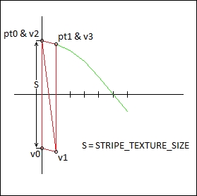
In the preceding figure, each horizontal segment (pt0 -> pt1) will be drawn by two triangles (v0, v1, v2) and (v1, v2, v3).
Along with the triangle vertices, the loop also calculates the texture coordinate for each of the vertices. Remember that texture coordinates usually go from 0 to 1. So, for the x component of the texture coordinate, we will divide the x component of the particular vertex by the size of the texture. Since the texture parameters are set to repeat, we don't need to worry about anything else.
For the y coordinate, we will just set the bottom texture coordinate to 0 and the top texture coordinate to 1. This way, the texture is fully distributed vertically. Finally, we update the prev_from_key_point_ and prev_to_key_point_ to from_key_point_ and to_key_point_, respectively. In this way, we have calculated the vertices and texture coordinates that will be used in the draw function.
The Update function of the Terrain class is called every tick from GameWorld with the penguin's position passed as an argument. The Update function takes care of two important tasks:
- It updates the position and scale of the hill based on the penguin's position
- It resets the current hill and generates a new one once the hill has left the screen
Let's see how this is done in the Update function of Terrain.cpp:
void Terrain::Update(CCPoint penguin_position)
{
  // determine current height & minimum height
  float height = penguin_position.y;
  const float min_height = SCREEN_SIZE.height * 0.6f;
  height = (height < min_height) ? min_height : height;

  // scale only if penguin is above SCREEN_SIZE.height * 0.6f
  float scale = min_height / height;
  setScale(scale * 1.25f);
  // update scrolling
  SetOffsetX(penguin_position.x);

  // check if terrain has left screen
  if(from_key_point_ >= MAX_HILL_KEY_POINTS - 1 && to_key_point_ >=
    MAX_HILL_KEY_POINTS - 1)
  {
    // reset the old data
    Reset();
    // create a new hill a couple of screens ahead of the penguin
    init(world_, penguin_position.x + SCREEN_SIZE.width * 2);
  }
}
We begin by storing the elevation of the penguin into the height variable. We also initialize another variable min_height with the value SCREEN_SIZE.height * 0.6f. We then use these variables to calculate the amount that the entire hill should be scaled into the scale variable. The calculation works in such a way that hill only scales down when the penguin's y coordinate has risen above 0.6 times the height of the screen. We also pass the x component of the penguin's position to the SetOffsetX function that we will discuss next.
The last part of the Update function checks to see whether the hill has scrolled out of the screen by comparing the values of the from_key_point_ and to_key_point_ variables. These variables specify the left-most and right-most key points of the visible area of the hill. Thus, if both variables are past the total number of key points, it is safe to say that the hill has left the screen.
In that case, we simply call the Reset function of Terrain, which makes sure that the striped sprite is released and the body's fixtures are destroyed while also resetting all the appropriate counters and variables. After Reset, we call the init function and pass in a reference to the physics world and the starting point for the next set of hills. We position the next set of hills a couple of screens ahead of the penguin, giving the players a second to catch their breath.
Let's now take a look at the SetOffsetX function that is responsible for scrolling the hills:
void Terrain::SetOffsetX(float offset_x)
{
  // update only if offset is different or if its a new game
  if (offset_x_ != offset_x || first_time_)
  {
    first_time_ = false;
    offset_x_ = offset_x;
    // leave some gap so the penguin is not stuck to the left
      of the screen
    setPositionX(SCREEN_SIZE.width / 8 - offset_x_ * m_fScaleX);

    // reset the drawable vertices of the hill
    ResetVertices();
  }
}
The if condition ensures that we proceed further only when the offset passed into this function is different from the existing offset or if this is the first time SetOffsetX is called. What follows next is code to set the position of the hill based on the offset and scale factor, while also allowing the player to stay 0.125 times the screen width ahead of the terrain. Finally, we call the ResetVertices function that will update the vertices and texture coordinates so the appropriate area of the hill is rendered.
At this point, our Terrain class is capable of generating a realistic yet beautiful striped texture, creating smooth and interpolated vertices for a hill. It also creates a physics body along those vertices, rendering itself and even scrolling and scaling itself. Now, it's time to look at the other main entity of the game: the Penguin class.