
Chapter 3
Peripherals and Expansion
THE FOLLOWING COMPTIA A+ 220-901 OBJECTIVES ARE COVERED IN THIS CHAPTER:
- ✓ 1.4 Install and configure PC expansion cards.
- Sound cards
- Video cards
- Network cards
- USB cards
- FireWire cards
- Thunderbolt cards
- Storage cards
- Modem cards
- Wireless/cellular cards
- TV tuner cards
- Video capture cards
- Riser cards
- ✓ 1.7 Compare and contrast various connection interfaces, their characteristics, and purpose.
- Physical connections:
- USB 1.1 vs. 2.0 vs. 3.0 (connector types: A, B, mini, micro)
- FireWire 400 vs. FireWire 800
- SATA1 vs. SATA2 vs. SATA3, eSATA
- Other connector types (VGA, HDMI, DVI, Audio [analog, digital (optical connector)], RJ-45, RJ-11, Thunderbolt)
- Wireless connections:
- Bluetooth
- RF
- IR
- NFC
- Characteristics:
- Analog
- Digital
- Distance limitations
- Data transfer speeds
- Quality
- DRM
- Frequencies
- Physical connections:
- ✓ 1.11 Identify connector types and associated cables.
- Display connector types:
- DVI-D
- DVI-I
- DVI-A
- DisplayPort
- RCA
- HD15 (i.e., DE15 or DB15)
- BNC
- miniHDMI
- miniDIN-6
- Display cable types:
- HDMI
- DVI
- VGA
- Component
- Composite
- Coaxial
- Device cables and connectors:
- SATA
- eSATA
- USB
- FireWire (IEEE1394)
- PS/2
- Audio
- Adapter and converters:
- DVI to HDMI
- USB A to USB B
- USB to Ethernet
- DVI to VGA
- Thunderbolt to DVI
- PS/2 to USB
- HDMI to VGA
- Display connector types:
- ✓ 1.12 Install and configure common peripheral devices.
- Input devices:
- Mouse
- Keyboard
- Scanner
- Barcode reader
- Biometric devices
- Game pads
- Joysticks
- Digitizer
- Motion sensor
- Touch pads
- Smart card readers
- Digital cameras
- Microphone
- Webcam
- Camcorder
- MIDI enabled devices
- Output devices:
- Printers
- Speakers
- Display devices
- Input & output devices:
- Touch screen
- KVM
- Smart TV
- Set-top box
- Input devices:
With the core system components of the typical personal computer system under your belt, it is time to turn our attention to some of the available peripherals that can be connected to the computer. In doing so, we will also discuss the interfaces and cable assemblies associated with those peripherals.
Installing and Configuring Expansion Cards
An expansion card (also known as an adapter card) is simply a circuit board that you install into a computer to increase the capabilities of that computer. Expansion cards come in varying formats for different uses, but the important thing to note is that no matter what function a card has, the card being installed must match the bus type of the motherboard into which it is being installed. For example, you can install a PCI network card into a PCI expansion slot only.
For today’s integrated components (those built into the motherboard), you might not need an adapter to achieve the related services, but you will still need to install drivers to make the integrated devices function with the operating system. As the trend toward more integrated components was maturing, many installers found most of the integrated components to be nonfunctional. A quick check in Device Manager showed a small collection of devices to be without their device drivers. Most motherboard manufacturers supply CD-ROM discs with their motherboards that contain all of the device drivers needed to get the built-in electronics recognized by the operating system. Execution of the disc’s setup program generally results in all components working and Device Manager clearing its warnings.
The following are the four most common categories of expansion cards installed today:
- Video
- Multimedia
- I/O
- Communications
Let’s take a quick look at each of these card types, their functions, and what some of them look like.
Video
A video adapter (more commonly called a graphics adapter or even more commonly a video card) is the expansion card that you put into a computer to allow the computer to display information on some kind of monitor. A video card is also responsible for converting the data sent to it by the CPU into the pixels, addresses, and other items required for display. Sometimes, video cards can include dedicated chips to perform some of these functions, thus accelerating the speed of display.
At a basic level, video adapters that have a PCI interface operate sufficiently. However, because AGP and PCIe slots offer more resources to the adapter, most manufacturers and computer owners prefer not to use PCI slots for video adapters. Although you might be able to find the rare motherboard that still offers an AGP slot, PCIe is the preferred expansion slot for video card attachment. The technology on which PCIe was designed performs better for video than those on which AGP and PCI are based. Figure 3.1 shows an example of a PCIe-based video card.
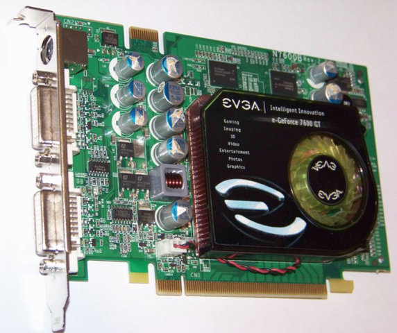
Figure 3.1 A video expansion card
Multimedia
The most basic and prolific multimedia adapter is the sound card. TV tuner cards and video capture cards are newer multimedia adapters that continue to gain in popularity due to decreasing cost and the rise of the Internet as a forum for creative sharing.
Sound Card
Just as there are devices to convert computer signals into printouts and video information, there are devices to convert those signals into sound. These devices are known as sound cards. Although sound cards started out as pluggable adapters, this functionality is one of the most common integrated technologies found on motherboards today. A sound card typically has small, round, 1/8″ jacks on the back of it for connecting microphones, headphones, and speakers as well as other sound equipment. Many sound cards used to have a DA15 game port, which can be used either for joysticks or MIDI controllers. Figure 3.2 shows an example of a legacy sound card with a DA15 game port.

Figure 3.2 A classic sound card
Sound cards today might come with an RCA jack (see the section “Audio/Video Jacks” later in this chapter). This is decidedly not for composite video. Instead, there is a digital audio specification known as the Sony/Philips Digital Interface (S/PDIF). Not only does this format allow you to transmit audio in digital clarity, but in addition to specifying an RCA jack and coaxial copper cabling, it specifies optical fiber connectors (TOSLINK) and cabling for electrically noisy environments, further increasing the transmission quality of the digital signal.
TV Tuner Cards and Video Capture Cards
The TV tuner card is a class of internal and external devices that allows you to connect a broadcast signal, such as home cable television, to your computer and display the output on the computer monitor. TV tuner cards come in analog, digital, and hybrid varieties. Most TV tuner cards act as video capture cards as well. A video capture card can also be a stand-alone device, and it is often used to save a video stream to the computer for later manipulation or sharing. Video-sharing sites on the Internet make video capture cards quite popular with enterprises and Internet socialites alike. TV tuner cards and video capture cards need and often come with software to aid in the processing of multimedia input.
I/O
I/O card is often used as a catchall phrase for any expansion card that enhances the system, allowing it to interface with devices that offer input to the system, output from the system, or both. The following are common examples of modern I/O cards:
- USB cards
- FireWire cards
- Thunderbolt cards
- Storage cards, such as eSATA
These cards are to be installed in a compatible slot on the motherboard. Their configuration is minimal, and it is usually completed through the Plug and Play process. Nevertheless, check the BIOS settings after installation for new entries in the menu structure. It’s the job of the BIOS to track all of the hardware in the system and supply resources as needed. For example, a new Thunderbolt expansion card might allow you to configure whether attached Thunderbolt devices should be allowed to wake the system, how long of a delay should be observed before waking the system, and various settings for how to use memory and other resources.
Communications
Communications adapters give a computer the ability to transmit information to other devices that might be too distant to cable up to directly. Network adapters and modems are the two most popular types of communications adapters. Network adapters are generally used within the administrative domain of a home or enterprise and rely on other devices to relay their transmissions around the world. In contrast, modems allow direct domestic or international communication between two devices across the Public Switched Telephone Network (PSTN). Although there are other devices in the PSTN, the service provider’s network appears as a cloud to the end stations, unlike the intermediate devices of a home or enterprise data network.
Network Interface Card (NIC)
A network interface card (NIC) is an expansion card that connects a computer to a network so that it can communicate with other computers on that network. NIC can also stand for network interface controller. It translates the data from the parallel data stream used inside the computer into the serial data stream that makes up the frames used on the network. It has a connector for the type of expansion bus on the motherboard (PCIe, PCI, and so on) as well as a connector for the type of network (such as fiber connectors, RJ-45 for UTP, antenna for wireless, or BNC for legacy coax). In addition to physically installing the NIC, you need to install drivers for the NIC in order for the computer to use the adapter to access the network. Figure 3.3 shows an example of a NIC.
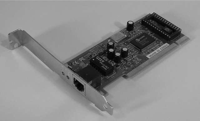
Figure 3.3 A network interface card
If you have a system with either no or too few Ethernet interfaces, it’s easy to find a USB-to-Ethernet adapter that uses an existing USB port to gain access to the energy needed to power the circuitry at the heart of the adapter’s Ethernet interface. The USB port is also used as the communication pathway for the now-powered Ethernet interface to transmit and receive across a standard Ethernet network. Figure 3.4 shows an example of a USB-to-Ethernet adapter, with the Ethernet interface in the foreground.

Figure 3.4 A USB-to-Ethernet adapter
Ash Kyd/USB Ethernet adapter Licensed under CC BY-SA 4.0 via Commons
Another type of USB-to-Ethernet converter on the market is a device that produces the opposite effect and uses an Ethernet network to extend the range of USB ports and devices, which are unable to extend beyond a few meters on their own. There is an ongoing effort by various groups, such as the USB/IP Project, to advance the state of the art regarding the use of networks to extend USB connectivity. Other vendors create client-server platforms, such as USB over Network, to create an environment that supports USB access over the network.
Wireless NICs
Wireless NICs have the unique characteristic of requiring that you configure their connecting device before configuring the NIC. Wired NICs can generally create a link and begin operation just by being physically connected out of the box to a hub or switch. The wireless access point or ad hoc partner computer must also be configured before secure communication, at a minimum, can occur by using a wireless NIC. These terms will be explained in greater detail in Chapter 8, “Installing Wireless and SOHO Networks.”
Cellular Cards
Almost every cellular service provider offers a line of adapters that can be installed into or inserted on the outside of desktop and laptop computers. Some advanced users have modified wireless access points to allow the insertion of such adapters into USB interfaces to act as the WAN gateway to obtain Internet access for their attached clients. In addition, depending on your service plan, most smartphones can be tethered to your computer and used as a cellular gateway. Very often, the cellular adapter comes with a setup program that configures the card for the service provider’s network. From that point, anytime you are in a cellular service area, you can use the adapter to gain access to the Internet through the provider or by roaming on the network of a partner or competitor with which an agreement has been reached in that area.
Today, it’s exceedingly common for cellular providers to offer devices like the one shown in Figure 3.5. Some of these devices use 3G or 4G cellular services to provide Internet access through the device. The LAN portion of the device creates an 802.11 wireless LAN to which 5, 10, or even more WiFi clients can attach.
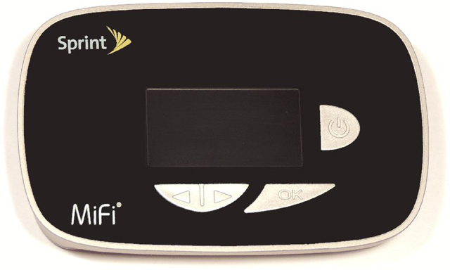
Figure 3.5 A cellular hotspot
Modem
Any computer that connects to the Internet using an analog dial-up connection needs a modem, or modulator/demodulator. A modem is a device that converts digital signals from a computer into analog signals that can be transmitted over phone lines and back again. These expansion card devices have one connector for the expansion bus being used (PCIe, PCI, and so on) and another for connection to the telephone line. Actually, as you can see in Figure 3.6, which shows an old ISA modem card, there might be two RJ-11 ports: one for connection to the telephone line and the other for connection to a telephone. This is primarily so that a phone can gain access to the same wall jack that the computer connects to without swapping their cords or using a separate splitter. Keep in mind, though, that you won’t be able to use the phone while the computer is connected to the Internet.
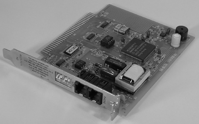
Figure 3.6 An internal analog modem
Riser Cards
An alternative motherboard form factor, known as New Low-Profile Extended (NLX), or one of its offshoots has been used in some types of low-profile cases. NLX places the expansion slots sideways on a special riser card to use the reduced vertical space optimally. Adapter cards that normally plug into expansion slots vertically in other motherboards plug in parallel to the motherboard, so their second most demanding dimension does not affect case height. Figure 3.7 shows a motherboard with its riser card attached.
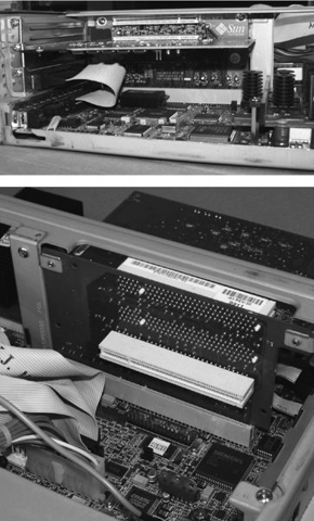
Figure 3.7 Both sides of a riser card with adapter
Riser technology also serves to free up valuable motherboard space for circuitry that cannot or should not be placed on adapters. Without the use of the riser, the motherboard would need to be made larger to accommodate the same circuitry. The term riser can also be used for any board that combines many functions into a single card, such as AMR and CNR (which were introduced in Chapter 1, “Motherboards, Processors, and Memory”), and don’t actually allow the attachment of additional cards to themselves the way true risers do.
Adapter Configuration
Expansion cards might require configuration. However, most can be recognized automatically by a Plug and Play operating system. In other words, resources are handed out automatically without jumper settings or the installation of device drivers is handled or requested automatically. Supplying the drivers might be the only form of configuration required. For example, unlike older ISA adapters, PCI adapters take care of requesting their own resources through Plug and Play. This is especially true of simple I/O adapters, such as those that provide USB and FireWire ports.
Some modern adapters, however, require more specific configuration steps during installation. For example, two or more PCIe graphics adapters that support SLI (see Chapter 1) must be bridged together with special hardware that comes with the adapters. Although most sound cards tend to work with no specific configuration, advanced features will need to be implemented through the operating system or through utilities that came with the adapter. Wired network adapters tend to be easier to configure than wireless ones. Wireless adapters often require the installation of a screw-on antenna, which should be postponed until after the card is fully inserted and physically secured in the system. Software configuration that allows these cards to communicate with a wireless access point can be challenging for the novice. Nevertheless, even wired NICs might require static configuration of certain protocol settings, such as IP addressing, duplex, and speed, in order for them to be productive. The functions of TV and video capture cards are sometimes not native to the operating system and therefore come with advanced utilities that must be learned and configured before the adapters will work as expected.
In any event, consult the documentation provided with your adapter for additional configuration requirements or options. The more specialized the adapter, the more likely it will come with specialty-configuration utilities.
Identifying Characteristics of Connectors and Cables
Now that you’ve learned the various types of items found in a computer, let’s discuss the various types of ports and cables used with computers. A port is a generic name for any connector on a computer or peripheral into which a cable can be plugged. A cable is simply a way of connecting a peripheral or other device to a computer using multiple copper or fiber-optic conductors inside a common wrapping or sheath. Typically, cables connect two ports: one on the computer and one on some other device.
Let’s take a quick look at some of the different styles of port connector types as well as peripheral port and cable types. We’ll begin by looking at peripheral port connector types.
Device Connector Types
Computer ports are interfaces that allow other devices to be connected to a computer. Their appearance varies widely, depending on their function. In the following sections, we’ll examine the following types of peripheral ports:
- D-subminiature
- RJ-series
- Other types
D-subminiature Connectors
D-sub connectors, for a number of years the most common style of connector found on computers, are typically designated with DXn, where the letter X is replaced by a letter from A through E, which refer to the size of the connector, and the letter n is replaced by the number of pins or sockets in the connector. D-sub connectors are usually shaped like a trapezoid and have at least two rows of pins with no other keying structure or landmark, as you can see in Figure 3.8.
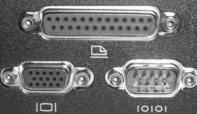
Figure 3.8 D-sub ports and connectors
The “D” shape ensures that only one orientation is possible. If you try to connect them upside down or try to connect a male connector to another male connector, they just won’t go together and the connection can’t be made. By the way, male interfaces have pins, while female interfaces have sockets. Be on the lookout for the casual use of DB to represent any D-sub connector. This is very common and is accepted as an unwritten de facto standard.
At the bottom left in Figure 3.8 is a DE15F 15-pin display-connector port, which may also be referred to as an HD15 or DB15 port. The other two interfaces are the classic parallel and serial ports.
RJ-Series
Registered jack (RJ) connectors are most often used in telecommunications. The two most common examples of RJ ports are RJ-11 and RJ-45. RJ-11 connectors are used most often on flat satin cables in telephone hookups; your home phone jack is probably an RJ-11 jack. The ports in older external and internal analog modems are RJ-11.
RJ-45 connectors, on the other hand, are larger and most commonly found on Ethernet networks that use twisted-pair cabling. Your Ethernet NIC likely has an RJ-45 jack on it. See Chapter 6, “Networking Fundamentals,” for details on networking interfaces. Although RJ-45 is a widely accepted description for the larger connectors, it is not correct. Generically speaking, Ethernet interfaces are 8-pin modular connectors, or 8P8C connectors, meaning that there are eight pin positions and all eight of them are connected, or used. RJ-45 specifies the physical appearance of the connector and also how the contacts are wired from one end to the other. Surprisingly, the RJ-45 specification does not match the TIA T568A and T568B wiring standards used in data communications.
Figure 3.9 shows an RJ-11 jack on the left and an RJ-45 jack on the right. Notice the size difference. As you can see, RJ connectors are typically square with multiple gold contacts on the flat side. A small locking tab on the other side prevents the connector and cable from falling or being pulled out of the jack casually.

Figure 3.9 RJ ports
Other Types of Ports
There are many other types of ports that are used with computers today, including these:
- Universal Serial Bus (USB)
- IEEE 1394 (FireWire)
- Infrared
- Audio and video jacks
- PS/2 (6-pin mini-DIN)
Let’s look at each one and how it is used.
Universal Serial Bus (USB)
Most computers built after 1997 have one or more flat ports in place of the original serial port. These ports are Universal Serial Bus (USB) ports, and they are used for connecting multiple (up to 127) peripherals to one computer through a single port (and the use of multiport peripheral hubs). USB version 1.x supports data rates as high as 12Mbps (1.5MBps). USB 2.0 supports data rates as high as 480Mbps (60MBps), 40 times that of its predecessor. USB 3.0 boasts data rates of 5Gbps, more than 10 times the rate of USB 2.0. Figure 3.10 shows an example of a set of Type A USB ports. Port types are explained in the section “Common Peripheral Cables and Their Interfaces” later in this chapter.

Figure 3.10 USB ports
Because of USB’s higher transfer rate, flexibility, and ease of use, most devices now come standard with USB interfaces. For example, digital cameras feature USB and FireWire as the preferred interfaces.
IEEE 1394 (FireWire)
While not as prevalent as USB ports, one other port has crept into the mainstream and is included as a standard attachment in small numbers, often only one, on motherboards and laptops. That port is the IEEE 1394 port (shown on a desktop PC in Figure 3.11 and on a laptop in Figure 3.12), more commonly known as a FireWire port. Its popularity is due to its ease of use, isochronous (synchronized clock) mode, and very high (400Mbps to 3.2Gbps and higher) transmission rates.
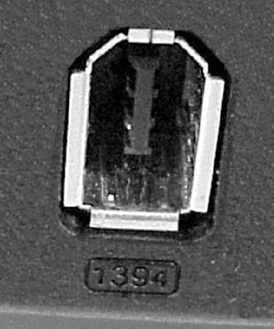
Figure 3.11 A 6-pin FireWire port on a PC
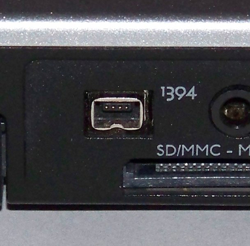
Figure 3.12 A 4-pin FireWire port on a laptop
Originally developed by Apple, it was standardized by IEEE in 1995 as IEEE 1394. It is often used as a way to get digital video into a PC so that it can be edited with digital video editing tools. Security applications benefit from FireWire’s higher power output, reducing the need for external power to devices such as security cameras. Audio/video enthusiasts also like this feature, and they rely on the capability of headend devices to control and synchronize the various media sources.
Look for a more thorough discussion of FireWire as a technology in the section “Common Peripheral Cables and Their Interfaces” later in this chapter.
Infrared
Many years ago, increasing numbers of people became fed up with being tethered to their computers by cords. As a result, many computers (especially portable computing devices like laptops and PDAs) hit the market with infrared ports to send and receive data. Modern computers use radio frequency (RF) technologies, such as Bluetooth and WiFi, to accomplish the same and more. RF technologies such as Bluetooth and WiFi are presented in more detail, including their speed and distance limitations, in Chapter 8, and Near Field Communication (NFC) is covered in Chapter 10.
An infrared (IR) port is a small port on the computer that allows data to be sent and received using electromagnetic radiation in the infrared band. The infrared port itself is a small, dark square of plastic (usually a very dark maroon) and can typically be found on the front of a PC or on the side of a laptop or portable. Figure 3.13 shows an example of an infrared port.
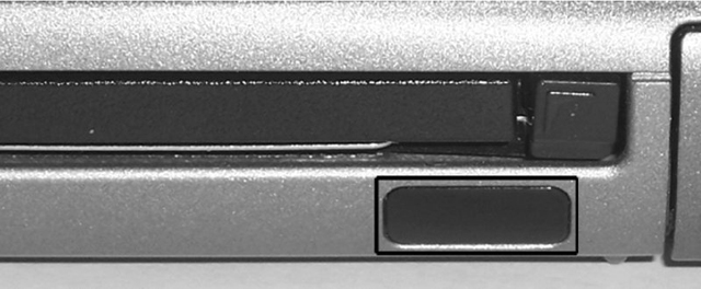
Figure 3.13 An infrared port
Part of the reason for their fall from grace is that infrared ports send and receive data at a very slow rate (the maximum speed on PC infrared ports is less than 16Mbps). Most infrared ports support the Infrared Data Association (IrDA) standard, which outlines a standard way of transmitting and receiving information by infrared so that devices can communicate with one another.
Note that although infrared is a wireless technology, it shares more characteristics with light than with radio waves. In fact, infrared pulses can be carried through the air or through optical fiber, just like visible light and laser light. As a result, most infrared communications, especially those that conform to the IrDA standards, are line-of-sight only and take place within a short distance (typically less than 4 meters). Infrared is generally used for point-to-point communications such as controlling the volume on a device with a handheld remote control.
IrDA is working on infrared standards that will push bit rates well into the Gbps range. Nevertheless, RF technologies that do not suffer from line-of-sight limitations might make advanced IrDA standards slow to take root.
Audio/Video Jacks
The RCA jack (shown in Figure 3.14) was developed by the RCA Victor Company in the late 1940s for use with its phonographs—the original record players. You bought a phonograph, connected the RCA plug on the back of your phonograph to the RCA jack on the back of your radio or television, and used the speaker and amplifier in the radio or television to listen to vinyl records. It made phonographs cheaper to produce, and it had the added bonus of making sure that everyone had an RCA Victor radio or television (or, at the very least, one with an RCA jack on the back). Either way, RCA made money.
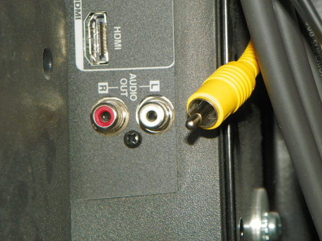
Figure 3.14 An RCA jack (female) and RCA plug (male)
Today, RCA jacks and connectors (or plugs) are used to transmit both audio and video information. Typically, when you see a yellow-coded RCA connector on a PC video card (next to a DE15F VGA connector, perhaps), it’s for composite video output (output to a television or VCR). However, digital audio can be implemented with S/PDIF, which can be deployed with an RCA jack. Figure 3.18, later in this chapter, shows an S/PDIF RCA jack. RCA jacks are considered coaxial because the outer circular conductor and the center pin that collectively make up the unbalanced single transmit/receive pair have the same axis of rotation; that is, co-axial. S/PDIF can also be implemented by TOSLINK fiber connectors. Toshiba’s TOSLINK interface is a digital fiber-optic audio technology that is implemented with its own connector.
Although they aren’t used for video, it bears mentioning that the 1/8″ stereo minijack and mating miniplug are still commonly used on computers these days for analog audio. Your sound card, microphone, and speakers have them. Figure 3.15 is a photo of a TOSLINK optical interface with a push-in/flip-up cover, pictured to the left of a set of standard analog minijacks.
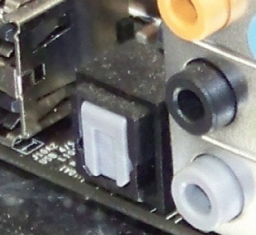
Figure 3.15 The TOSLINK interface
In the spirit of covering interfaces that support both audio and video, don’t forget the HDMI interface, which carries both over the same interface. Only CATV coaxial connections to TV cards can boast that on the PC. An RCA jack and cable carry either audio or video, not both simultaneously.
PS/2 (Keyboard and Mouse)
Another common port, as mentioned earlier, is the PS/2 port. A PS/2 port (also known as a mini-DIN 6 connector) is a mouse and keyboard interface port first found on the IBM PS/2 (hence the name). It is smaller than previous interfaces (the DIN 5 keyboard port and serial mouse connector), and thus its popularity increased quickly. Figure 3.16 shows examples of both PS/2 keyboard and mouse ports. When the color of the ports is visible, you can tell the difference because the keyboard port is usually purple and the mouse port is usually green. Also, typically there are small graphics of a keyboard and mouse, respectively, imprinted next to the ports.

Figure 3.16 PS/2 keyboard and mouse ports
Common Peripheral Cables and Their Interfaces
An interface is a method of connecting two dissimilar items together. A peripheral interface is a method of connecting a peripheral or accessory to a computer, including the specification of cabling, connector and port type, speed, and method of communication used.
The most common interfaces used in PCs today include (in no particular order):
- Drive interfaces
- USB
- IEEE 1394 (FireWire)
- RJ-45
- Audio (RCA and TOSLINK)
- PS/2
Let’s look at the cabling and connectors used as well as the type(s) of peripherals that are connected to such interfaces.
Hard Disk Connectors
Almost every computer made today uses some type of disk drive to store data and programs until they are needed. All drives need some form of connection to the motherboard so that the computer can “talk” to the disk drive. Regardless of whether the connection is built into the motherboard (onboard)—it could reside on an adapter card (off-board)—the standard for the attachment is based on the drive’s requirements. These connections are known as drive interfaces. The interfaces consist of circuitry and a port, or header.
Today, the headers that you will find on most motherboards are for Serial ATA (SATA), the speeds of which were discussed in Chapter 2. The SATA headers are vastly different from classic HDD headers. Figure 3.17 shows an example of the SATA data connector. Consult Chapter 2 for additional information on SATA and eSATA connectors and their flat data cables.

Figure 3.17 The Serial ATA connector
Common Ports and Connectors
For a computer to be useful and have as much functionality as possible, there must be a way to get the data into and out of it. Many different ports are available for this purpose. The following sections continue the discussion of port and connector types started earlier in the chapter, but it also introduces additional information on those already mentioned and other interfaces.
Briefly, the seven most common types of ports that you will see on a computer are Universal Serial Bus (USB), FireWire/IEEE 1394, eSATA, video, Ethernet, digital/analog sound in/out, and PS/2 keyboard and mouse. Figure 3.18 shows some of these and others on a docking station, or port replicator, for a laptop. From left to right, the interfaces shown are as follows:
- DC power in
- Analog modem RJ-11
- Ethernet NIC RJ-45
- S-video out—legacy
- DVI-D (dual-link) out
- SVGA out
- Parallel (on top)—legacy
- Standard serial—legacy
- Mouse (on top)
- Keyboard
- S/PDIF (out)
- USB
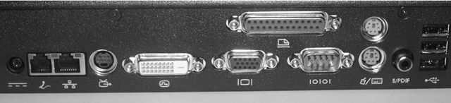
Figure 3.18 Peripheral ports and connectors
Analog Sound Jacks
Figure 3.19 shows another set of interfaces not seen in Figure 3.18, the sound card jacks. These jacks are known as 1/8″ (3.5mm) stereo minijacks, so called for their size and the fact that they make contact with both the left and right audio channels through their tip, rings (if they have any), and sleeve.
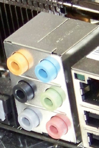
Figure 3.19 Sound card jacks
A six-jack setup capable of 8-channel audio is shown in the photo, also known as 7.1 surround sound. The 7 represents the seven full-bandwidth channels and the 1 represents the one low-frequency effects (LFE) channel, most often attached to the subwoofer. Each of the full-bandwidth channels is often represented by its own speaker in the system, but not necessarily. If there is a 1:1 channel-to-speaker representation, the eight speakers in 8-channel 7.1 are generally placed equidistant from the audience as follows, with all angles measured from front center (usually where the video source resides):
- One center speaker at 0 degrees (at the video source)
- Left and right front speakers at 22 to 30 degrees
- Left and right side speakers at 90 to 110 degrees
- Left and right rear speakers at 135 to 150 degrees
- One subwoofer possibly hidden anywhere in the room
The right column of jacks shown in Figure 3.19 represents the classic three minijacks found on sound cards. The middle one is a green output jack used for 2-channel audio, usually manifested as two full-bandwidth speakers, one each on the left and right channels. Both channels are provided by the single green stereo minijack. The other two are input interfaces; the top jack is the blue line-in interface, designed for audio sources that lack a specialized interface, such as less expensive musical keyboards and phonographs, for example, so audiophiles can convert their vinyl collections to digital. The bottom one is the pink microphone input jack.
If you understand the concept of 8-channel 7.1, then 4-channel 3.1 and 6-channel 5.1 will be simpler to understand. The left column of jacks in Figure 3.19 was added for dedicated surround sound use, and it comprises the orange jack at the top for the center and subwoofer channels (used for 3.1, 5.1, and 7.1), the black middle jack for the rear left and right surround channels (used for 5.1 and 7.1), and the gray jack at the bottom for the side left and right surround channels (used only for 7.1 surround sound). With 3.1, 5.1, and 7.1, the green jack is adopted for the front stereo channel. Technically, 3.1 is not surround sound because there are only front and center channels and no surround channels.
Most installers place the rear speakers in 5.1 at the rearmost position recommended for the 7.1 side speakers, about 110 degrees from front center. When you’re migrating to 7.1, these rear speakers are repurposed as side speakers and new ones are installed as 7.1 rear speakers, at an angle starting from about 135 degrees.
Software can use these interfaces to allow you to record and play back audio content in file—MP3, for instance—or CD/DVD form. Note, however, that the jacks themselves are not distinctive in their physical characteristics. They are uniquely addressable, but it is up to the software’s programming to assign their purpose. Most programmers, of course, respect the color code. As a case study, for motherboards that support surround sound but do not supply the black and orange jacks, you have to use the blue jack for both line-in and rear surround and the pink jack for both microphone and center/subwoofer. Depending on the software in use, you would need to swap one plug manually for another because the jack functions would change.
Universal Serial Bus (USB)
USB cables are used to connect a wide variety of peripherals to computers, including keyboards, mice, digital cameras, printers, and scanners. Not all USB cables maximize the potential of all USB ports. USB 1.x cables cannot provide USB 2.0 and 3.0 performance; USB 2.0 cables cannot provide USB 3.0 performance. Good or bad, depending on how you look at it, the interfaces accept all cable connectors. So, ensuring that your cable is built to the specification that you intend to use, whether version 2.0 or 3.0, is of utmost importance. Otherwise, the connected device will have to fall back to the maximum version supported by the cable. This is usually not an issue, except for the lost performance, but some high-performance devices will refuse to operate at reduced levels.
Table 3.1 details the differences in the maximum speeds defined by the three groups of USB specifications. Note that these speeds are not generally attainable due to a variety of factors, but USB 3.0 has the greatest likelihood of attaining its maximum rate because of its full-duplex nature. Note that all specifications are capable of Low Speed 1.5Mbps performance.
Table 3.1 USB speed limitations
| Specification | Maximum Speed | Speed Trade Name |
| USB 1.0/1.1 | 12Mbps | Full Speed |
| USB 2.0 | 480Mbps | High Speed |
| USB 3.0 | 5Gbps (5000Mbps) | SuperSpeed |
The USB technology is fairly straightforward. Essentially, it was designed to be Plug and Play—just plug in the peripheral and it should work, providing that the software is installed to support it. Many standard devices have drivers that are built into the common operating systems or automatically downloaded during installation. More complex devices come with drivers to be installed before the component is connected.
USB cable varies mostly based on the USB peripheral connector on the external-device end. Because there can be quite a number of USB devices on a single system, it helps to have a scheme to clarify their connectivity. The USB standard specifies two broad types of connectors. They are designated Type A and Type B connectors. A standard USB cable has some form of Type A connector on one end and some form of Type B connector on the other end. Figure 3.20 shows four USB 1.x/2.0 cable connectors. From left to right, they are as follows:
- Type A
- Standard Mini-B
- Type B
- Alternate Mini-B
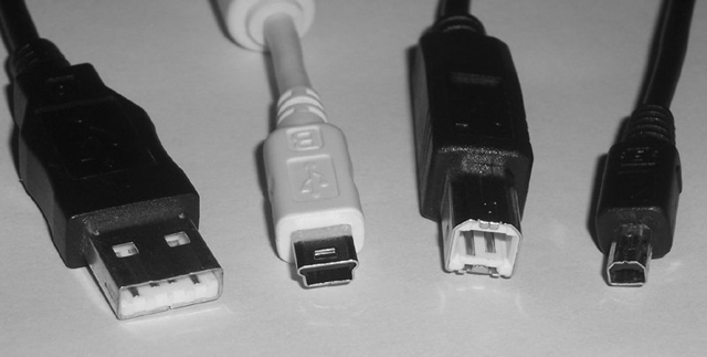
Figure 3.20 USB cables and connectors
Modern small form factor devices, including many phones and smaller digital cameras, use a Micro-B connector, shown in Figure 3.21, that is smaller than the standard Mini-B shown in Figure 3.20.
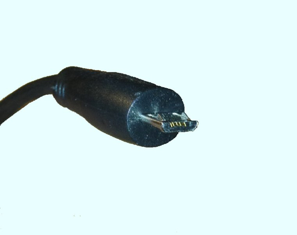
Figure 3.21 USB Micro-B connector
The specification for USB 3.0, also known as SuperSpeed, recommends a standard blue color coding for all interfaces and cables as a way of differentiating them from legacy cables and interfaces. The connectors also feature five additional pins that are not accessible to 1.x/2.0 connectors and receptacles shown in Figure 3.18 and Figure 3.20.
One part of the USB interface specification that makes it so appealing is the fact that if your computer runs out of USB ports, you can simply plug a device known as a USB hub into one of your computer’s USB ports, which will give you several more USB ports from one original port. Figure 3.22 shows an example of a USB hub.
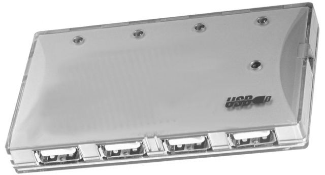
Figure 3.22 A USB hub
Be aware of the limitations in the USB specification. Table 3.2 details the cable-length limitations for each of the three families of USB. The third column simply shows the combined length of all six cables used with five hubs and a sixth cable connected to the component. If you use hubs, you should never use more than five hubs between the system and any component.
Table 3.2 USB cable-length limitations
| Specification | Maximum Cable Length | Total Cable with Five Hubs |
| USB 1.0/1.1 | 3m | 18m |
| USB 2.0 | 5m | 30m |
| USB 3.0 | 3m | 18m |
In addition to the cable length difference between USB 2.0 and 3.0, there are a host of other differences between these specifications. The following items outline some of the primary differences.
Shielding USB 3.0 requires that each pair in the cable assembly be shielded to withstand the electromagnetic interference (EMI) inherent with transmissions at higher frequencies.
Connectors Although all connectors are compatible with all receptacles, to attain SuperSpeed performance, SuperSpeed connectors with five additional pins must be used on cables and receptacles. These pins do not obstruct the four legacy pins required for backward compatibility. Instead, they sit farther back and are accessible only to compatible interfaces.
Bursting and streaming USB 2.0 does not support bursting, the low-duration, excessively fast transmission of data, nor does it support streaming, the continuous flow of data between two endpoints once the flow has begun. USB 3.0 supports continuous bursting as well as streaming.
Duplex USB 2.0 is a half-duplex technology, meaning that all devices must share a common bandwidth, making overall performance appear subpar. USB 3.0, on the other hand, supports dual simplex communications pathways that collectively imitate full-duplex transmission, where devices at both ends of the cable can transmit simultaneously.
Media access method USB 2.0 peripheral devices must wait until polled by the host before transmitting data. USB 3.0 endpoints use an asynchronous transmission mechanism, similar to that of Ethernet, where data is transmitted at will.
Host control The host (computer system) is the only device in the USB 2.0 specification that can control power management. The endpoints are the only devices that can participate in error detection and recovery as well as flow control. USB 3.0 endpoints can all control when they enter low-power mode to conserve power. Error handling and flow control are performed on each link in USB 3.0, not just at the endpoints.
Power USB 2.0 provides a maximum of 100 milliamperes (mA) of current at low power and 500mA at high power. USB 3.0 provides 150mA and 900mA, respectively, allowing for the direct powering of some of the same component types that FireWire is capable of powering but that USB 2.0 is not.
Through the use of a 7-bit identifier, providing 27 = 128 possible addresses, no more than 127 devices, including hubs, should be connected back to a single USB host controller in the computer, not that you would ever want to approach this number. The 128th identifier, the highest address, is used for broadcasting to all endpoints. No interconnection of host controllers is allowed with USB; each one and its connected devices are isolated from other host controllers and their devices. As a result, USB ports are not considered networkable ports. Consult your system’s documentation to find out if your USB ports operate on the same host controller.
From the perspective of the cable’s plug, Type A is always oriented toward the system from the component. As a result, you might notice that the USB receptacle on the computer system that a component cables back to is the same as the receptacles on the USB hub that components cable back to. The USB hub is simply an extension of the system, and it becomes a component that cables back to the system. Each hub takes one of the 127 available addresses.
Type B plugs connect in the direction of the peripheral component. Therefore, you see a single Type B interface on the hub as well as on the peripheral endpoints to allow them to cable back to the system or another hub. Although they exist, USB cables with both ends of the same type, a sort of extension cable, are in violation of the USB specification. Collectively, these rules make cabling your USB subsystem quite straightforward.
Despite the letter of the standards and the seemingly locked-up logic of USB connectivity, it is occasionally necessary to alter the interface type at one end of a USB cable. For that reason, there is a variety of simple, passive converters on the market with a Type A interface on one side and a Type B interface on the other. Such devices allow some form of Type A connector on the cable to connect to a Type A port and a Type B connector to attach to a Type B port. These USB A to USB B converters should be purchased based on the compatibility of the two connectors on each end of the converter.
IEEE 1394 (FireWire)
The IEEE 1394 interface is about two things, if nothing else: speed and efficiency. Its first iteration, now known as FireWire 400, has a maximum data throughput of 400Mbps in half duplex. Although the numbers imply that USB 2.0 at 480Mbps might outperform FireWire 400, the truth is that FireWire allows a closer saturation of the bandwidth by its devices due to its different encoding mechanism. USB devices are lucky to achieve half of their bus’s rated bandwidth during sustained operation. The other major difference between the two technologies is the amount of power accessible to FireWire devices. Whereas USB provides less than an ampere of current at 5VDC, FireWire specifications allow for the provision of 1.5A at up to 30VDC (and slightly more in some implementations). This production of 45W of power allows for larger devices to be powered by the FireWire interface, obviating the need for separate external power.
The next iteration, FireWire 800 (specified under IEEE 1394b), has a maximum data throughput of 800Mbps and works in full duplex. FireWire 400 carries data over a maximum cable length of 4.5 meters with a maximum of 63 devices connected to each interface on the computer. Using new beta connectors and associated cabling, including a fiber-optic solution, FireWire 800 extends to 100 meters. When implemented over copper, FireWire 800, like FireWire 400, is limited to 4.5m cable runs. IEEE 1394b also allows for 1.6Gbps (S1600) and 3.2Gbps (S3200) implementations, but it’s still, interestingly, referred to as FireWire 800. IEEE 1394c standardized the running of FireWire over the same Category 5e infrastructure that supports Ethernet, including the use of RJ-45 connectors. However, with the advent of more advanced technologies, not the least of which is Thunderbolt, IEEE 1394c may well prove to be a standard on paper only.
FireWire (also known as i.LINK in Sony’s parlance) uses a very special type of six-wire cable, as shown on the left in Figure 3.23, for FireWire 400. Only four wires are used when power is not supplied by the interface. These interfaces are collectively known as alpha connectors. Notice the difference in the system end on the left and the component end on the right. It is difficult to mistake this cable for anything but a FireWire cable. FireWire 800 uses a nine-wire implementation with beta connectors. A beta connector and one of the FireWire logos (another is a stylized “1394”) are shown on the left of Figure 3.35 later in this chapter. Alpha and beta originally referred to the different encoding methods used with FireWire 400 and FireWire 800.
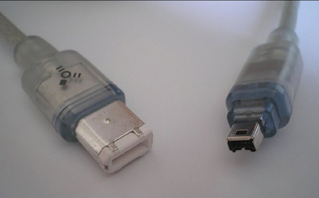
Figure 3.23 A FireWire (IEEE 1394) 6- to 4-pin alpha cable
IEEE1394-4-6pin. Con licenza Pubblico dominio tramite Wikipedia
Although most people think of FireWire as a tool for connecting their digital camcorders to their computers, it’s much more than that. Because of its high data transfer rate, it is being used more and more as a universal, high-speed data interface for things like hard drives, optical drives, and digital video editing equipment.
Because the FireWire specification was conceived to allow peripherals to be networked together in much the same fashion as intelligent hosts are networked together in LANs and WANs, a quick introduction to the concept of networking is in order (see Chapter 6 for more detail on networking concepts). A topology can be thought of as the layout of the nodes that make up the endpoints and connecting devices of the network. One of the most popular topologies today is the star topology, which uses a central concentrating device that is cabled directly to the endpoints. A tree structure is formed when these concentrating devices are interconnected to one another, each attached to its own set of endpoints. One or few concentrators appear at the first tier of the tree, sort of like the “root system” of the tree. These root devices are expected to carry more traffic than other concentrators because of their position in the hierarchy. In subsequent tiers, other concentrators branch off from the root and each other to complete the tree analogy.
The 1995 IEEE 1394 specification that is equivalent to FireWire 400 allows 1023 buses, each supporting 63 devices, to be bridged together. This networkable architecture supports more than 64,000 interconnected devices that can communicate directly with one another instead of communicating through a host computer in the way that USB is required to do. Star and tree topologies can be formed as long as no two devices are separated by more than 16 hops. A hop can be thought of as a link between any two end devices, repeaters, or bridges, resulting in a total maximum distance between devices of 72 meters.
Through an internal hub, a single end device can use two IEEE 1394 ports to connect to two different devices, creating a daisy-chained pathway that allows the other two devices to communicate with one another as well. The device in the middle, which can be the computer system or any peripheral device, affords a physical pathway between the other two devices but is not otherwise involved in their communication with one another. Contrast this function to that of the USB host which, prior to version 3.0, had to be involved in all transactions. USB 3.0 does not provide bridged networking the way that FireWire does, but it allows the devices to initiate communication and other transactions.
RCA
The RCA cable is a simple coaxial cable. There are two connectors, usually male, one on each end of the cable. There are two contacts on each connector, the ground ring and the positive data pin in the middle. The male connector connects to the female connector on the equipment. Figure 3.24 shows an example of an RCA cable. An RCA male to RCA female connector is also available; it’s used to extend the reach of audio or video signals.
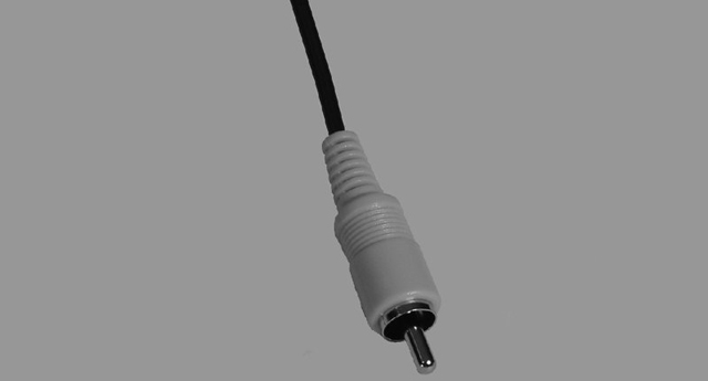
Figure 3.24 An RCA cable
The RCA male connectors on a connection cable are sometimes plated in gold to increase their corrosion resistance and to improve longevity.
PS/2 (Keyboard and Mouse)
The most important input device for a PC is the keyboard. All PC motherboards contain some sort of connector that allows a keyboard to be connected directly to the motherboard through the case. There are two main types of wired keyboard connectors. At one time, these were the AT and PS/2 connectors. Today, the PS/2-style connector may be included but has largely been replaced by the USB port for wired keyboard attachment. The all-but-extinct original AT connector is round, about ½″ in diameter, in a 5-pin DIN configuration. Figure 3.25 shows an example of the AT-style keyboard connector.
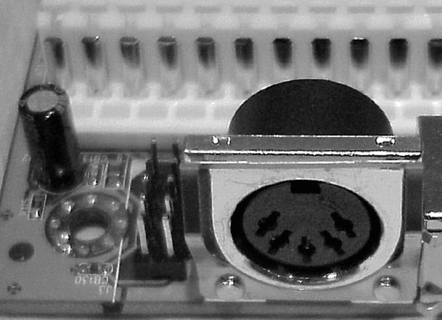
Figure 3.25 An AT connector on a motherboard
The PS/2 connector (as shown in Figure 3.26) is a smaller 6-pin mini-DIN connector. Until recently, PCs included a PS/2 keyboard connector as well as a PS/2 mouse connector right above it on the motherboard. Today, you might see a single double-use connector or none at all, in favor of USB or wireless attachment.
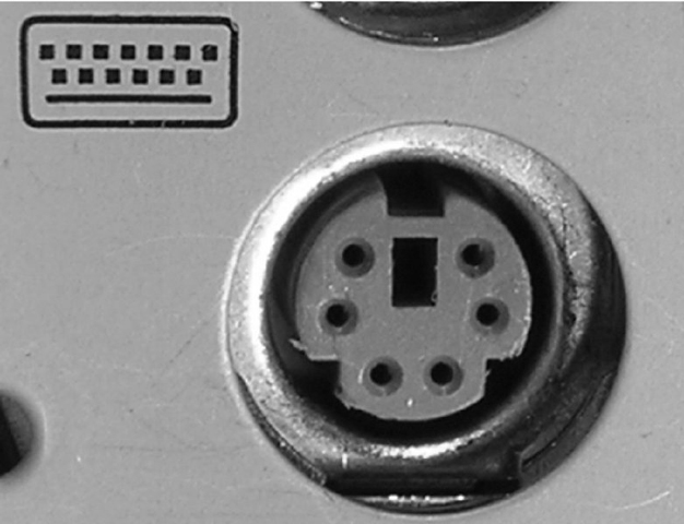
Figure 3.26 A PS/2-style keyboard connector on a motherboard
Wireless keyboard and mouse attachment is fairly popular today, and it is most often achieved with Bluetooth technology or a proprietary RF implementation.
Some keyboards and mice today still come with a PS/2-to-USB adapter to change their USB connector into the PS/2 interface. Using the PS/2 connector that still comes with some motherboards saves one or two USB interfaces. Manufacturers sometimes opt for a single PS/2 connector with half purple and half green color codes, indicating that either device can be attached to the same interface. However, in these situations, only one of the two types of devices can be connected at a time. Figure 3.27 shows an example of a PS/2 keyboard cable.

Figure 3.27 A PS/2 keyboard cable
Video Display Cables and Connectors
While the analog VGA-spawned standards might keep the computing industry satisfied for years yet to come, the sector in the market driving development of non-VGA specifications has become increasingly more prevalent. These high-resolution, high-performance junkies approach video from the broadcast angle. They are interested in the increased quality of digital transmission. For them, the industry responded with technologies like DVI and HDMI. The computing market benefits from these technologies as well. DVI interfaces on graphics adapters and laptops became commonplace. In increasingly more cases, HDMI interfaces take adapters to the next generation.
Other consumers desire specialized methods to connect analog display devices by splitting out colors from the component to improve quality or simply to provide video output to displays not meant for computers. For this group, a couple of older standards remain viable: component video and composite video. The following sections present the details of these two specifications as well as DVI and HDMI.
DVI
In an effort to leave analog VGA standards and return to digital video, which can typically be transmitted farther and at higher quality than analog, a series of connectors known collectively as Digital Visual (or Video) Interface (DVI) was developed for the technology of the same name. These digital interfaces offer much higher performance than the original digital standards, such as CGA and EGA. At first glance, the DVI connector might look like a standard D-sub connector, but on closer inspection, it begins to look somewhat different. For one thing, it has quite a few pins, and for another, the pins it has are asymmetrical in their placement on the connector. Figure 3.28 illustrates the five types of connectors that the DVI standard specifies. Also look at an actual photo of the DVI-I interface in Figure 3.29 and the dual-link DVI-D interface in Figure 3.30.

Figure 3.28 Types of DVI connector
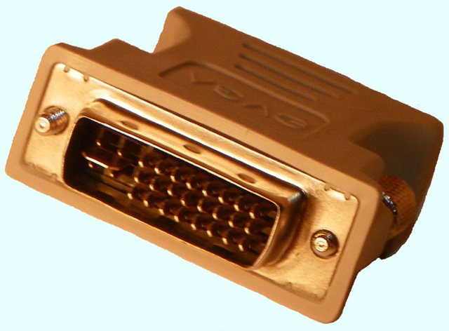

Figure 3.29 DVI-A–to–VGA adapter
One thing to note about analog vs. digital display technologies is that all graphics adapters and all monitors deal with digital information. It is only the connectors and cabling that can be made to support analog transmission. Before DVI and HDMI encoding technologies were developed, consumer digital video display connectors could not afford the space to accommodate the number of pins that would have been required to transmit 16 or more bits of color information per pixel. For this reason, the relatively few conductors of the inferior analog signaling in VGA were appealing.
There are three main categories of DVI connectors:
DVI-A An analog-only connector. The source must produce analog output, and the monitor must understand analog input.
DVI-D A digital-only connector. The source must produce digital output, and the monitor must understand digital input.
DVI-I A combination analog/digital connector. The source and monitor must both support the same technology, but this cable works with either a digital or an analog signal.
The DVI-D and DVI-I connectors come in two varieties: single link and dual link. The dual-link options have more conductors—taking into account the six center conductors—than their single-link counterparts, which accommodate higher speed and signal quality. The additional link can be used to increase resolution from 1920×1080 to 2048×1536 for devices with a 16:9 aspect ratio or from WUXGA to WQXGA for devices with a 16:10 aspect ratio. Of course, both components, as well as the cable, must support the dual-link feature. Consult Chapter 4, “Display Devices,” for more information on display standards.
DVI-A and DVI-I analog quality is superior to that of VGA, but it’s still analog, meaning that it is more susceptible to noise. However, the DVI analog signal will travel farther than the VGA signal before degrading beyond usability. Nevertheless, the DVI-A and VGA interfaces are pin-compatible, meaning that a simple passive DVI-to-VGA adapter, as shown in Figure 3.29, is all that is necessary to convert between the two. As you can see, the analog portion of the connector, if it exists, comprises the four separate color and sync pins and the horizontal blade that they surround, which happens to be the analog ground lead that acts as a ground and physical support mechanism even for DVI-D connectors.
It’s important to note that DVI-I cables and interfaces are designed to interconnect two analog or two digital devices; they cannot convert between analog and digital. DVI cables must support a signal of at least 4.5 meters, but better cable assemblies, stronger transmitters, and active boosters result in signals extending over longer distances.
HDMI
High-Definition Multimedia Interface (HDMI) is an all-digital technology that advances the work of DVI to include the same dual-link resolutions using a standard HDMI cable but with higher motion-picture frame rates and digital audio right on the same connector. HDMI cabling also supports an optional Consumer Electronics Control (CEC) feature that allows transmission of signals from a remote control unit to control multiple devices without separate cabling to carry infrared signals.
HDMI cables, known as Standard and High Speed, exist today in the consumer space. Standard cables are rated for 720p resolution as well as 1080i, but not 1080p. High Speed cables are capable of supporting not only 1080p, but also the newer 4K and 3D technologies.
In June 2006, revision 1.3 of the HDMI specification was released to support the bit rates necessary for HD DVD and Blu-ray disc. This version also introduced support for “deep color,” or color depths of at least one billion colors, including 30-, 36-, and 48-bit color. However, not until version 1.4, which was released May 28, 2009, was the High Speed HDMI cable initially required.
With version 1.4 came HDMI capability for the controlling system—the television, for instance—to relay Ethernet frames between its connected components and the Internet, alleviating the need for each and every component to find its own access to the LAN for Internet access. Both Standard and High Speed cables are available with this Ethernet channel. Each device connected by such a cable must also support the HDMI Ethernet Channel specification, however.
Additional advances that were first seen in version 1.4 were 3D support, 4K resolution (but only at a 30Hz refresh rate), an increased 120Hz refresh rate for the 1080 resolutions, and an audio return channel (ARC) for televisions with built-in tuners to send audio back to an A/V receiver without using a separate output cable. Version 1.4 also introduced the anti-vibration Type E locking connector for the automotive-video industry and cables that can also withstand vibration as well as the hot/cold extremes that are common in the automotive world.
Version 2.0 of HDMI (2013) introduced no new cable requirements. In other words, the existing High Speed HDMI cable is fully capable of supporting all new version 2 enhancements. These enhancements include increasing the 4K refresh rate to 60Hz, a 21:9 theatrical widescreen aspect ratio, and 32-channel audio. Note that 7.1 surround sound comprises only eight channels, supporting the more lifelike Rec. 2020 color space and multiple video and audio streams to the same output device for multiple users. Version 2.0a, released in 2015, primarily added high dynamic range (HDR) video, but it does not require any new cables or connectors.
The HDMI connector is not the same as the one used for DVI. Nevertheless, the two technologies are electrically compatible. HDMI is compatible with DVI-D and DVI-I interfaces through proper adapters, but HDMI’s audio and remote-control pass-through features are lost. Additionally, 3D video sources work only with HDMI. Figure 3.30 shows a DVI-to-HDMI adapter between DVI-D and the Type A 19-pin HDMI interface. The first image is the DVI-D interface, and the second is the HDMI interface on the other side of the adapter. Compare the DVI-D interface to the DVI-I interface of Figure 3.29, and note that the ground blade on the DVI-D connector is narrower than that of the DVI-A and DVI-I connectors. The DVI-D receptacle does not accept the other two plugs for this reason, as well as because the four analog pins around the blade have no sockets in the DVI-D receptacle.


Figure 3.30 HDMI-to-DVI adapter
Unlike DVI-D and, by extension DVI-I, DVI-A and VGA devices cannot be driven passively by HDMI ports directly. An HDMI-to-VGA adapter must be active in nature, either powered externally or through the HDMI interface itself.
There is also a Type B connector that has 29 pins and is intended to support higher resolution for the components that use it. HDMI version 1.3 specified a smaller 19-pin Type C connector for portable devices. The Type C connector, also referred to as a miniHDMI connector, is compatible with the Type A connector but it still requires an adapter due to its smaller size. HDMI version 1.4 specified two more interfaces: Type D and Type E. If Type C is a miniHDMI interface, then you might refer to the Type D connector as microHDMI. Figure 3.31 shows a Type D HDMI connector to the right of a Micro-B USB connector on a smartphone. Also compatible with Type A interfaces because they have the same 19 pins, Type D interfaces require but a simple adapter for conversion.

Figure 3.31 Type D HDMI interface
HDMI cables should meet the signal requirements of the latest specification. As a result, and as with DVI, the maximum cable length is somewhat variable. For HDMI, cable length depends heavily on the materials used to construct the cable. Passive cables tend to extend no farther than 15 meters, while adding electronics within the cable to create an active version results in lengths as long as 30 meters. Twisted-pair and fiber cabling options can extend cabling to 50 meters and 100 meters, respectively.
Component Video
When analog technologies outside the VGA realm are used for broadcast video, you are generally able to get better-quality video by splitting the red, green, and blue components in the signal into different streams right at the source. The technology known as component video performs a signal-splitting function similar to RGB separation. However, unlike RGB separation, which requires full-bandwidth red, green, and blue signals as well as a fourth pathway for synchronization, the most popular implementation of component video uses one uncompressed signal and two compressed signals, reducing the overall bandwidth needed. These signals are delivered over coax either as red, green, and blue color-coded RCA plugs or similarly coded BNC connectors, the latter being seen mostly in broadcast-quality applications.
The uncompressed signal is called luma (Y), which is essentially the colorless version of the original signal that represents the “brightness” of the source feed as a grayscale image. The component-video source also creates two compressed color-difference signals known as Pb and Pr. These two chrominance (chroma, for short) signals are also known as B – Y and R – Y, respectively, because they are created by subtracting out the luma from the blue and red source signals. It might make sense, then, that the analog technology presented here is most often referred to and labeled as YPbPr. A digital version of this technology, usually found on high-end devices, replaces analog’s Pb and Pr with Cb and Cr, respectively, and is most often labeled YCbCr. Figure 3.32 shows the three RCA connectors of a component video cable.
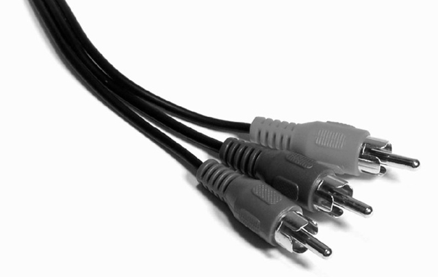
Figure 3.32 A component video cable
Note that in the foregoing discussion, there is no mention of a green component-video signal. In fact, the often green-colored lead in the component-video cable carries the luma. There is no need for a separate green color-difference signal. Essentially, the luma signal is used as a colorless map for the detail of the image. The receiving display device adds the luma signal from the Y lead back to the blue and red color-difference signals that were received on the Pb and Pr leads, re-creating compressed versions of the full blue and red source signals. Whatever details in the luma version of the image have weak representation in the blue and red versions of the image are inferred to be green.
Therefore, you can conclude that by providing one full signal (Y) and two compressed signals (Pb and Pr) that are related to the full signal (Pb = B – Y and Pr = R – Y), you can transmit roughly the same information as three full signals (R, G, and B) but with less bandwidth. Incidentally, component video is capable of transmitting HD video at full 1080p (1920×1080, progressive-scan) resolution. However, the output device is at the mercy of the video source, which often is not manufactured to push 1080p over component outputs.
Composite Video
When the preceding component video technologies are not feasible, the last related standard, composite video, combines all luma and chroma leads into one. Composite video is truly the bottom of the analog-video barrel. However, the National Television System Committee (NTSC) signal received by over-the-air antennas or by cable-TV feeds is composite video, making it a very common video signal. Unfortunately, once the four signals are combined into one, the display equipment has no way of faithfully splitting them back out, leading to less than optimal quality but great cost efficiency.
A single yellow RCA jack, the composite video jack is rather common on computers and home and industrial video components. While still fairly decent in video quality, composite video is more susceptible to undesirable video phenomena and artifacts, such as aliasing, cross coloration, and dot crawl. If you have a three-connector cable on your home video equipment, such as a DVD player connected to a TV, odds are that the tips will be yellow, red, and white. The red and white leads are for left and right stereo audio; the yellow lead is your composite video.
DisplayPort
DisplayPort is a royalty-free digital display interface from the Video Electronics Standards Association (VESA) that uses less power than other digital interfaces and VGA. A simple adapter allows HDMI and DVI voltages to be lowered to those required by DisplayPort because it is functionally similar to HDMI and DVI. DisplayPort cables can extend 3 meters unless an active cable powers the run, in which case the cable can extend to 33 meters.
The DisplayPort (DP) connector latches itself to the receptacle with two tiny hooks in the same manner as micro-B USB connectors. A push-button mechanism serves to release the hooks for removal of the connector from the receptacle. Figure 3.33 shows the 20-pin DP interface at the end of a cable. Note the beveled keying at the bottom right corner of the connector.
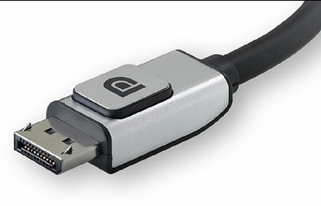
Figure 3.33 A full-size DisplayPort connector
Displayport-cable by Belkin - http://www.belkin.com/pressroom/releases/uploads/ 01_07_08DisplayPortCable.html. Licensed under CC BY-SA 3.0 via Wikimedia Commons
The DisplayPort standard also specifies a smaller connector, known as the Mini DisplayPort (MDP) connector. The MDP is electrically equivalent to the full-size DP connector and features a beveled keying structure, but it lacks the latching mechanism present in the DP connector. Although Figure 3.35 depicts a Thunderbolt port (designated by a lightning bolt with an arrowhead), you are essentially looking at the MDP port, repurposed for use as the more advanced Thunderbolt interface, discussed next. Figure 3.34 shows a Thunderbolt/MDP connector on the end of a cable.

Figure 3.34 A Thunderbolt/Mini DisplayPort connector
“Mini displayport” by Palthrow - Own work. Licensed under CC BY-SA 3.0 via Commons
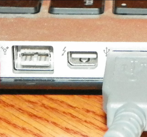
Figure 3.35 A Thunderbolt interface
Thunderbolt
The DisplayPort is being usurped by a smaller compatible—also digital—version called Thunderbolt, created in collaboration between Intel and Apple. Thunderbolt combines x4 PCI Express 2.0 with the DisplayPort 1.x technology. The most common Thunderbolt cable is a copper, powered active cable extending as far as 3m, which was designed to be less expensive than an active version of a DisplayPort cable of the same length. There are also supported optical cables in the specification that can reach as far as 60m but that terminate with the same copper MDP connector, by way of an embedded conversion chip.
Figure 3.35 shows a Thunderbolt interface on an Apple MacBook Pro. Note the standard lightning-bolt insignia by the port. To the left of the Thunderbolt port in the image is a 9-pin IEEE 1394b (FireWire) beta port. Despite its diminutive size, the Thunderbolt port has 20 pins around its connector bar, like its larger DisplayPort cousin. Of course, the functions of all of the pins do not directly correspond between the two interface types because Thunderbolt adds PCIe functionality.
Thunderbolt as a Data Interface
Because Thunderbolt includes a separate I/O function from the DP video technology, it is rated for power and transfer rates in the same way as are technologies such as USB, FireWire, and eSATA. Both of the initial versions of Thunderbolt, v1 and v2, operate at 20Gbps of aggregate bandwidth. The v2 offering does so with more flexibility by combining the two 10Gbps channels instead of allowing each one to perform as either only transmit or only receive. Each Thunderbolt port provides a total of 18V and 9.9W of power to the one or more attached peripherals.
Additionally, and as is the case with USB and FireWire, Thunderbolt devices can be daisy-chained and connected via hubs. Daisy chains can extend six levels deep for each controller interface, and each interface can optionally drive a separate monitor, which should be placed alone on the controller’s interface or at the end of a chain of components attached to the interface.
Thunderbolt Converters
Until the industry fully supports Thunderbolt on peripheral devices targeted by the technology, there is a need to be able to convert the ports on a computer to the standards that are most commonly supported by manufacturers of those peripherals.
Consumers can spend hundreds of dollars on hubs that split the system’s Thunderbolt port into a variety of ports. A more modest alternative is one of a family of much less expensive converters that target specific applications. One such converter, a Thunderbolt-to-DVI converter, is shown in Figure 3.36. Note that standard converters allow a DisplayPort interface or Thunderbolt port on the system to drive a DVI monitor and not for a DVI port to drive a Thunderbolt or DP monitor. You can use simple, inexpensive passive converters when the monitor supports the same pin functions as does Thunderbolt, such as when the Thunderbolt port is connecting to a DVI-D interface on the monitor. Passive converters support resolutions as high as 1080p (1920×1080, progressive-scan).
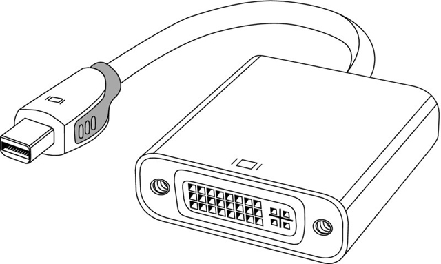
Figure 3.36 A Thunderbolt/MDP-to-DVI converter
Converters are also available that connect Thunderbolt and DisplayPort connectors on the computer to analog VGA monitors. Still others are made to allow Thunderbolt ports to connect to digital HDMI monitors. Active converters that contain chips to perform the conversion are necessary in situations such as when the technology is not directly pin-compatible with Thunderbolt, as with VGA and DVI-A analog monitor inputs, for example. Active converters are only slightly more expensive than their passive counterparts but still only a fraction of the cost of Thunderbolt hubs. One other advantage of active connectors is that they can support resolutions of 4K (3840×2160) and higher.
Coaxial
Two main forms of coaxial cable are used to deliver video from a source to a monitor or television. One of them is terminated by RCA or BNC plugs and tends to serve a single frequency, while the other is terminated by F connectors, those seen in cable television (CATV) settings, and tends to require tuning/demodulation equipment to choose the frequency to display. The terms that refer to whether a single frequency or multiple frequencies are carried over a cable are baseband and broadband, respectively. Figure 3.37 shows an example of the F connector most commonly used in home and business CATV installations. This is a 75-ohm form of coax known as RG-6.
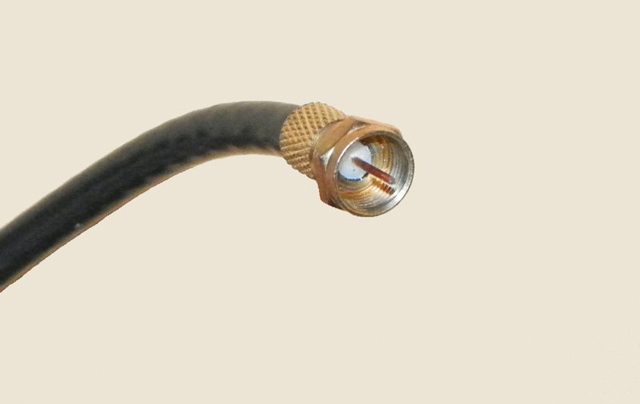
Figure 3.37 A CATV F connector and coaxial cable
Digital Rights Management
Digital rights management (DRM) is a series of technologies aimed at protecting against the piracy of digital entertainment media. Graphics display standards such as DVI, HDMI, and DisplayPort support one or more forms of DRM. Early versions of DisplayPort included DisplayPort Content Protection (DPCP) from Philips. Later versions of DisplayPort and HDMI include Intel’s High-bandwidth Digital Content Protection (HDCP).
HDCP operates by encrypting the stream of media over the connection between transmitter and receiver. Components must be licensed for HDCP by Digital Content Protection, LLC. In addition to sources and sinks—devices that can render the encrypted content for display—HDCP allows for repeaters that can decrypt the stream, adjust it for such features as increased resolution and amplified audio, and then re-encrypt it for transmission to the sink.
Input Devices
An input device is one that transfers information from outside the computer system to an internal storage location, such as system RAM, video RAM, flash memory, or disk storage. Without input devices, computers would be unable to change from their default boot-up state. The following sections detail different classes of input devices and a hub of sorts, used for switching between the most common of these devices. We will also demonstrate the similarities shared by devices that provide input to computer systems as well as their differences. Installation considerations will be presented where appropriate. The following input devices are covered in the subsequent sections:
- Mouse
- Touchpad
- Keyboard
- Scanner
- Barcode reader
- Digitizer
- Biometric devices
- Gamepads and joysticks
- Motion sensor
- Smart card reader
- Multimedia devices
Mouse
Although the computer mouse was born in the 1970s at Xerox’s Palo Alto Research Center (PARC), it was in 1984 that Apple made the mouse an integral part of the personal computer with the introduction of the Macintosh. In its most basic form, the mouse is a hand-fitting device that uses some form of motion-detection mechanism to translate its own physical two-dimensional movement into onscreen cursor motion. Many variations of the mouse exist, including trackballs, tablets, touchpads, and pointing sticks. Figure 3.38 illustrates the most recognizable form of the mouse.
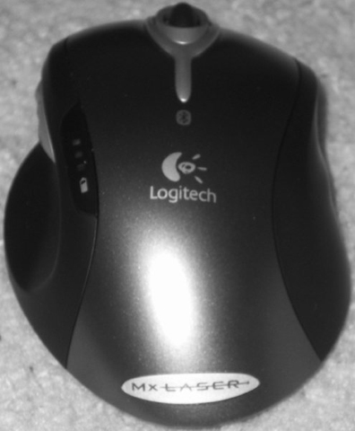
Figure 3.38 A computer mouse
The motion-detection mechanism of the original Apple mouse was a simple ball that protruded from the bottom of the device so that when the bottom was placed against a flat surface that offered a slight amount of friction, the mouse would glide over the surface but the ball would roll, actuating two rollers that mapped the linear movement to a Cartesian plane and transmitted the results to the software interface. This method of motion detection remains available today, although it’s fairly unpopular.
Later technologies used optical receptors to catch LED light reflected from specially made surfaces purchased with the devices and used like a mouse pad. A mouse pad is a special surface that improves mechanical mouse traction while offering very little resistance to the mouse itself. As optical science advanced for the mouse, lasers were used to allow a sharper image to be captured by the mouse, providing more sensitivity in motion detection. Certain surfaces don’t lend themselves well to standard laser-mouse functionality, but a higher resolution version exists that can even track across the surface of glass. The mouse today can be wired to the computer system or connected wirelessly. Wireless versions use batteries to power them, and the optical varieties deplete these batteries more quickly than their mechanical counterparts.
The final topic is one that is relevant for any mouse: buttons. The number of buttons that you need your mouse to have is dependent on the software interfaces you use. For the Macintosh, one button has always been sufficient, but for a Windows-based computer, at least two are recommended, hence the term right-click. Today, the mouse is commonly found to have a wheel on top to aid in scrolling and other specialty movement. The wheel has even developed a click in many models, sort of an additional button underneath the wheel. Buttons on the side of the mouse that can be programmed for whatever the user desires are more common today as well and can alarm the unsuspecting user the first time they grab such a mouse the wrong way.
Touchpads, which are flat panels below the spacebar, and pointing sticks, which are eraser-like protrusions in the middle of the keyboard, are found mainly on laptops. A trackball, however, is more like an inverted mouse, so let’s look at how they compare. Both devices place the buttons on the top, which is where your fingers will be. A mouse places its tracking mechanism on the bottom, requiring that you move the entire assembly as an analogue for how you want the cursor on the screen to move. In contrast, a trackball places the tracking mechanism, usually a ball that is larger than that of a mouse, on the top with the buttons. You then have a device that need not be moved around on the desktop and can work in tight spaces and on surfaces that would be incompatible with the use of a mouse. The better trackballs place the ball and buttons in such a configuration that your hand rests ergonomically on the device, allowing effortless control of the onscreen cursor.
Touchpad
Many modern laptops have a built-in pointing device that can take the place of a mouse. Touchpads are flat panels, which are most often positioned in the same plane as the keyboard—between the spacebar and the user—sometimes with buttons that supply the left- and right-clicks of the mouse. The user controls the onscreen pointer by tracing its path on the surface of the touchpad, some of which include a tactile click feature that takes the place of the left-button click. Some touchpads also dedicate an edge to the right-click function.
Touchpads can be purchased as separate external devices for use with any computer that has an available port, often USB. These work with laptops and desktops alike. Regardless of the details surrounding the touchpad, Windows offers one or more tabs dedicated to the touchpad in the Mouse applet in Control Panel for use in configuring the various settings for it. Tabs added by the manufacturer of the hardware often include advanced configuration options, including those related to multitouch and motions.
Figure 3.39 shows a manufacturer’s tab added to the Mouse applet in Control Panel. Figure 3.40 shows the additional configuration tabs produced by clicking the Options button shown in Figure 3.39.

Figure 3.39 Manufacturer tab in Mouse applet
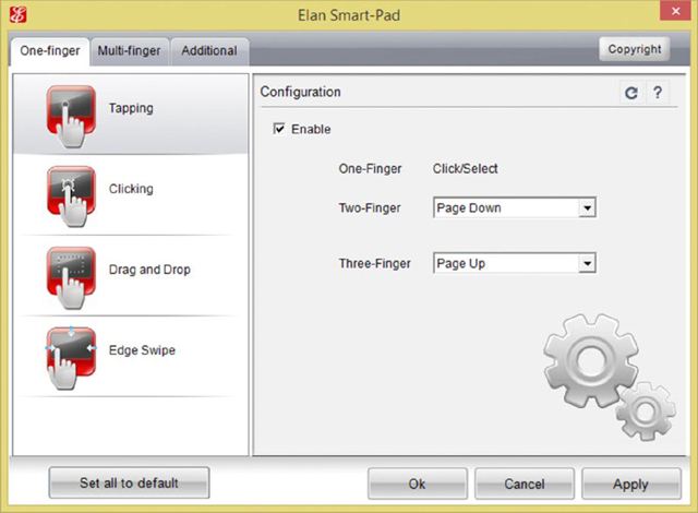
Figure 3.40 Manufacturer’s custom tabs
Keyboard
More ubiquitous than the mouse, the keyboard is easily the most popular input device, so much so that it’s more of a necessity. Very few users would even think of beginning a computing session without a working keyboard. Fewer still would even know how. The U.S. English keyboard places keys in the same orientation as the QWERTY typewriter keyboards, which were developed in the 1860s.
In addition to the standard QWERTY layout, modern computer keyboards often have separate cursor-movement and numerical keypads. The numerical keys in a row above the alphabet keys send scan codes to the computer that are different from those sent by the numerical keypad. At the discretion of the programmer, any given application might require the use of only one of the two sets of numeric keys or allow the use of either. The IBM PC/AT keyboard had only 84 keys, lacking separate cursor-movement keys. These functions were superimposed on the numeric keypad only. The Num Lock key had to be toggled to switch between cursor movement and the numeric keypad. The 101-key keyboard did include these separate keys but still kept the Num Lock arrangement as well, and the popular 104-key Windows keyboard added Windows-specific keys to those 101 keys.
Keyboards have also added function keys (not to be confused with the common laptop key labeled Fn), which are often placed in a row across the top of the keyboard above the numerical row. Key functionality can be modified by using one or more combinations of the Ctrl, Alt, Shift, and laptop Fn keys along with the normal QWERTY keys.
Technically speaking, the keys on a keyboard complete individual circuits when each one is pressed. The completion of each circuit leads to a unique scan code that is sent to the keyboard connector on the computer system. The computer uses a keyboard controller chip or function to interpret the code as the corresponding key sequence. The computer then decides what action to take based on the key sequence and what it means to the computer and the active application, including simply displaying the character printed on the key.
In addition to the layout for a standard keyboard, other keyboard layouts exist, some not nearly as popular, however. For example, without changing the order of the keys, an ergonomic keyboard is designed to feel more comfortable to users as they type. The typical human’s hands do not rest with the fingers straight down. Ergonomic keyboards, therefore, should not place keys flat and along the same plane. To accomplish that goal, manufacturers split the keyboard down the middle, angling keys on each side downward from the center. Doing so fits the keys to the fingers of the hands when they are in a relaxed state. Figure 3.41 shows an example of an ergonomic keyboard.
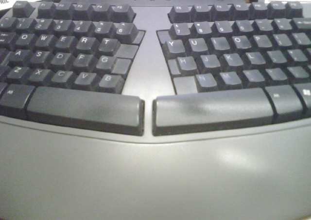
Figure 3.41 An ergonomic keyboard
My keyboard by ryaninc - Flickr. Licensed under CC BY 2.0 via Commons
The Dvorak Simplified Keyboard, patented in 1936, was designed to reduce fatigue in the hands of typists by placing characters that are more commonly used in the home row, among other physiologic enhancements. The QWERTY layout was designed to keep the hammers of a typewriter from becoming entangled. Although the Dvorak keyboard makes logical sense, especially in light of the historic decline in manufacturing and sales of the classic typewriter, the QWERTY keyboard remains dominant. One reason why the Dvorak keyboard has failed to take over might be the loss of productivity to a touch-typist as they retrain on the new format.
Scanner
One of the earliest input devices aside from the keyboard and mouse was the scanner. Today, most scanners feature USB, network (often as part of a multifunction device), or some form of wireless attachment. Look for a menu item in applications capable of scanning that specifies TWAIN (the generic term for the class of drivers associated with scanners), such as Select TWAIN Source. This selection allows you to choose from among multiple scanners before initiating the scan job.
Scanners use light to reflect off of a surface and measure the relative reflections of the different dots that make up the grid that the scanner is able to detect. The tighter the grid (the more dots per inch [DPI] supported), the higher the resolution of the resulting image. Charge coupled devices (CCDs) are a common choice in today’s scanners. CCDs convert the light they receive into electrical impulses, which is then forwarded to the software producing the scan for further processing into an image that is a facsimile of the original object being scanned.
A flatbed scanner evokes the concept of a copier with the paper handling and printing mechanisms missing. This image is not far off, which is why copiers make wonderful scanners, as long as they can produce a digital image file. It’s also why multifunction devices are so prolific; it takes very little to outfit a printer with a scanner component to be used for input to the computer and as a fax-scanning device. Inbound faxes can be printed, or the same digital interface that the scanner uses can be used to transfer the image electronically to software in the computer. Figure 3.42 shows the top flatbed scanner portion of a laser multifunction device that provides a way to print, scan, and fax.
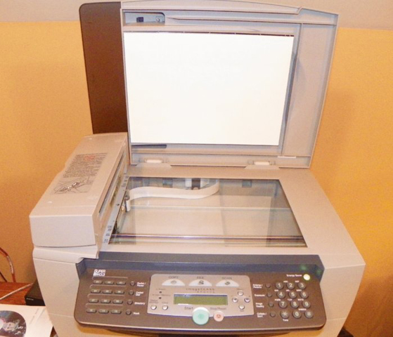
Figure 3.42 A flatbed scanner
Figure 3.43 shows you one of numerous brands of portable document scanners. These handy little devices are scarcely more than a foot long and can make short work of scanning anything from a business card to a gas receipt to an 8.5" × 11" lodging folio. The associated software that comes with these scanners performs optical character recognition (OCR), and it can recognize the orientation of the text and glean pertinent information from the documents scanned to populate the internal database. From this database, you can produce reports for such purposes as expenses, invoicing, and taxes. This model also offers the option to create a PDF during the scan instead.
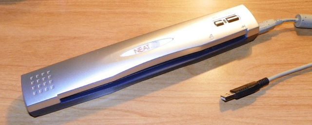
Figure 3.43 A portable document scanner
Barcode Reader
A barcode reader (or barcode scanner) is a specialized input device commonly used in retail and other industrial sectors that manage inventory. The systems to which the reader connects can be so specialized that they have no other input device. Barcode readers can use LEDs or lasers as light sources and can scan one- or two-dimensional barcodes.
Barcode readers can connect to the host system in a number of ways, but serial connections, such as USB, are fairly common. If the system uses proprietary software to receive the reader’s input, the connection between the two might be proprietary as well. Classic software interfaces called for the reader to be plugged into the keyboard’s PS/2 connector using a splitter, or “wedge,” which allows the keyboard to remain connected. The scanner converts all output to keyboard scans so that the system treats the input as if it came from a keyboard. For certain readers, wireless communication with the host is also possible, using IR, RF, Bluetooth, WiFi, and more.
With today’s smartphone technology being what it is, the built-in cameras can act as scanners, and the scanning app can interpret what the camera sees. In this way, Universal Product Code (UPC) barcodes and Quick Response (QR) codes and other 2D matrix barcodes can be input and processed. The smartphone can then use its Internet access to launch the application associated with the text, such as a web browser or an email client. A QR code is an encoded image that allows the scanning application to decode large amounts of text, and it can be used to represent simple text or popular strings, such as a website’s URL, a phone number, a GEO location, an email address, or an SMS message. Figure 3.44 is a simple QR code that will direct a QR-code reader app to the www.sybex.com website.

Figure 3.44 A QR code
Digitizer
One way to reproduce incredibly good artwork faithfully in digital form for computer use is to place the analog artwork on top of a sensor and use a stylus to trace the artwork after choosing an onscreen “crayon” or “pen.” The end result can be a work of art almost as good as the original. The device used to trace an analog source and turn it into a digital representation is a digitizer. Digitizing, in fact, is the act of turning any analog source—artwork, audio, video, slides and photographs—into a binary bit stream. As an input device, however, a digitizer or digitizing tablet takes pen strokes in the analog world and turns them into a digital rendering through the software controlling the digitizer. These devices are also commonly used to annotate presentations with the option to save or discard the annotations with each presentation. Figure 3.45 shows an example of a USB-attached digitizing tablet with choice of pen or mouse for input.
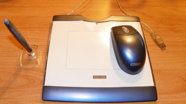
Figure 3.45 A digitizing tablet
Biometric Devices
Any device that measures one or more physical or behavioral features of an organism is considered a biometric device, or literally, a device that measures life. When the same device forwards this biometric information to the computer, it becomes an input device. The list includes fingerprint scanners, retinal and iris scanners, voice recognition devices, and facial recognition devices, to name a few. A computer can use this input to authenticate the user based on preestablished biometric information captured during user setup. Even cipher locks that authenticate personnel before allowing entry to secure environments can be replaced with biometric devices.
Because there are many manufacturers of biometric devices, the installation of any particular model is best performed while consulting the company’s documentation. If the device is not built into the computer, at a minimum some form of interface, such as USB, must be used to attach the device, and software must be installed to lock the system until authentication occurs. Many offerings allow multiple forms of authentication to be required in sequence. An example of a highly secure approach to authentication with multiple factors would be a biometric scan, followed by a challenge that requires a code from a token card, followed finally by the opportunity to enter a password. This “something you are, something you have, and something you know” technique works to secure some of the world’s most sensitive installations. Further discussion of the concept of multifactor authentication is beyond the scope of this book.
Gamepads and Joysticks
As long as there have been gaming applications for the personal computer, there have been standard and specialty controllers for some of those games. For the rest, the keyboard and mouse could be or had to be used for controlling the game. Two popular types of controllers have been the generic joystick, a controller with one or more buttons and a stick of varying length and girth, and the often proprietary gamepad, usually comprising function and directional buttons specific to the gaming console in use. Through the years, standardized PC connections have included the DA15 game port, also known as the joystick port, the RS-232 port, and the USB port. Figure 3.46 shows a wired joystick connected through the wireless controller for the Nintendo Wii video game console.

Figure 3.46 A proprietary gamepad
Motion Sensor
One of the first commercially viable motion sensors as an input device for a computing platform was found in the Nintendo Wii gaming system. Eventually, Sony’s Move and Microsoft’s Kinect joined the Wii in the marketplace, with the two later entrants being add-ons to their manufacturers’ existing game systems.
In the PC market, motion sensors as input devices are more likely to be seen as replacements for the mouse, trackball, trackpad, and other built-in pointing devices. One primary benefit of these devices, such as the Leap Motion Controller by Leap Motion, Inc., is that a user can control the movement of an onscreen cursor without physically laying a hand on any sort of component. Because such devices are not based on proven technology, the computer market does not seem to be flocking toward them—at least initially. But there might be hidden benefits in the end.
Repetitive strain injuries (RSIs) that stem from holding the hand against an object such as a mouse in a less than optimal position for extended periods of time do not occur when there is no contact. While there is no guarantee that users of motion sensors will not develop habits that may lead to RSIs, they will more likely exercise the same muscles and joints that would otherwise become damaged and begin pinching adjacent nerves. Even when handheld controllers are required, as in the case of the Wii system, the relative freedom from holding your hand in the same position for prolonged periods is a major benefit, despite holding it against the controller.
Smart Card Reader
As more and more organizations discover the value in multifactor authentication for access to their computing assets, smart card readers have become indispensable as an instrument of the “something you have” principle. For quite some time, the United States government and its military forces have relied on common access cards (CACs), which serve as visual identification cards as well as chip-based smart cards.
A smart card reader attaches to the system internally or externally by USB or sometimes through a dedicated adapter. FireWire was once supported, but it is no longer common for reader attachment. The reader provides power for the chip that is embedded in the smart card. These chips contain a combination of RAM, ROM, PROM, and a 16-bit CPU. Figure 3.47 shows the contacts of the integrated circuit chip (ICC) of a typical smart card.

Figure 3.47 A smart card showing the ICC
It’s increasingly common for merchants to install terminals that capture a patron’s credit card for the duration of the transaction if an ICC is detected, in contrast to requiring that the customer insert and then quickly remove the card from the classic reader. These new ICC-friendly card readers can also be used with the traditional cards that have no chip embedded.
The chip on a smart card may contain one or more PKI certificates. Smart card readers used by the United States Department of Defense are able to access the CAC’s ICC in order to use an identification certificate in the chip to verify the identity of the bearer. A PIN, however, may still be required to establish two-factor authentication. In other uses, card readers access digital-signature and encryption certificates to establish nonrepudiation and confidentiality for a user during electronic exchanges of information.
Multimedia Input Devices
Multimedia input devices vary in functionality based on the type of input being gathered. Two broad categories of multimedia input are audio and video. Digital motion and still cameras are incredibly popular as a replacement for similar video products that do not transfer information to a computer, making sharing and collaboration so much easier than before. The following sections present information on these multimedia input devices:
- Webcams
- MIDI-enabled devices
- Digital cameras and camcorders
- Microphone
Webcams
Years ago, owing to the continued growth in the Internet’s popularity, video camera–only devices known as webcams started their climb in popularity. Today, anyone who does a fair amount of instant messaging, whether professional or personal, has likely used or at least been introduced to webcams, often used in conjunction with messaging user interfaces.
Webcams make great security devices as well. Users can keep an eye on loved ones or property from anywhere that Internet access is available. Care must be taken, however, because the security that the webcam is intended to provide can backfire on the user if the webcam is not set up properly. Anyone who happens upon the web interface for the device can control its actions if there is no authentication enabled. Some webcams provide a light that illuminates when someone activates the camera. Nevertheless, it is possible to decouple the camera’s operation and that of its light.
A webcam connects directly to the computer through an I/O interface, such as USB or WiFi, and it does not have any self-contained recording mechanism. Its sole purpose is to transfer its captured video directly to the host computer, usually for further transfer over the Internet, hence the term web. Webcams that have built-in wired and wireless NIC interfaces for direct network attachment are prevalent as well. A now maturing evolution of the webcam for laptops resulted in manufacturers building the device into the bezel of the display. Connectivity is generally through an internal USB or FireWire interface.
MIDI Devices
Microphones, audio playback, and audio synthesizing devices are common input components connected to a sound card or some form of serial port so that audio from these devices can be collected and processed. As an example, consider Musical Instrument Digital Interface (MIDI) devices, called controllers, which create messages describing, and thus synthesizing, the user’s intended musical performance. These devices do not make sound that is recorded directly; they are merely designed to somewhat realistically fabricate the music the instruments that they represent might produce. MIDI files, therefore, are much smaller than files that contain digitized audio waveforms.
Modern MIDI controllers use 5-pin DIN connectors that look like the original AT keyboard connector. Controllers can be interconnected in one of two ways. The original method is to provide devices with two ports, an input and an output port, and daisy-chain them in a ring. This arrangement introduces a delay caused by devices processing and retransmitting messages that were not destined for them but instead for devices downstream from them. One solution is to replace the output port with one that merely replicates the input signal. If the receiving device is the intended destination, then the unnecessarily repeated message is ignored by downstream recipients. Otherwise, the actual recipient receives its message with far less delay. The second method of connection is another solution that reduces delay. A device with one input and multiple outputs interconnects many devices directly.
Regardless of the controller interconnection method, computers can receive MIDI controllers directly, such as through a sound card with a built-in MIDI interface or through the use of an external MIDI interface that originally connected to the computer’s game port. Today, USB and FireWire ports are more commonly used. Ethernet-attached interfaces also exist and require very little processing power to convert the MIDI messages into Ethernet frames.
Digital Cameras and Camcorders
A digital camera is a device that takes still pictures and records them to digital media of some sort for later access. A camcorder is a video capture device that performs a similar function to that of the digital camera but for moving video. Most of today’s multimedia recording devices perform the functions of both the digital camera and the digital camcorder. Depending on the device, both pictures and video can be stored on the same or different media within the same device. In fact, the most basic smartphone can perform both of these functions, often with exceptional quality.
Early versions of digital cameras relied on the storage media of the day, 3∼HF" floppy diskettes, for instance. Eventually, models with internal flash memory were developed, which led to hybrid models that also featured a memory card slot, resulting in the flexibility to grow the camera’s storage capacity as the technology produced larger cards.
A similar evolution occurred in the world of camcorders. Originally, camcorders required one of a variety of analog tape formats on which to record. This gave way to digital tape formats and then to burnable optical discs, hard disk drives, and today’s high-capacity flash storage devices. Once a removable memory card was added, the possibilities for what can be recorded and how much can be stored became nearly limitless. Figure 3.48 shows a digital camcorder on the left and a digital camera on the right.
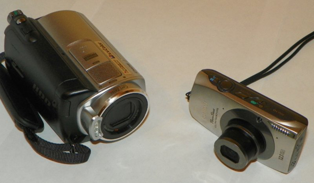
Figure 3.48 A digital camera and camcorder
The mechanism by which the digital information is transferred to a computer varies somewhat among these devices. In some cases, a cable—USB, for instance—can be attached between the device and the computer. A drive icon might then appear in Windows File Explorer, or you might have a specific application for access to the content. In other cases, removable media is for recording, and this media is then removed and transferred directly to a reader on the computer system, be it an optical drive or card reader. Certain manufacturers have developed docking stations for their product line. The dock can remain attached to the computer system, and the device can be interfaced to the dock, usually by simply sitting it down on the docking station. In some cases, these stations also charge the device while it is docked.
Microphone
Although discussed throughout this chapter, the microphone has yet to be formally defined, a definition which is at once technical and simple. Microphones convert sound waves into varying electrical signals. The result can be recorded, transmitted, or altered in a variety of ways, including amplification.
When installing a microphone, you must match its connector with an available one on the computer. Modern choices include the classic analog pink TRS connector and USB. Wireless versions also exist, but their receiver might still be connected to a standard I/O port. Alternatively, the microphone could be paired with a built-in Bluetooth transceiver, in which case, installation amounts to the pairing process.
Configuring a microphone on a PC is most often performed through the Recording tab of the Sound applet in Control Panel. Options include setting the levels and choosing enhancements, such as noise suppression and echo cancellation. Specialized applications may also have internal configuration for the microphone, passing most details of the configuration back to the operating system.
Output Devices
The process for the installation and configuration of certain output devices varies almost as widely as the number of models within a given category. Nevertheless, certain high-level steps must be taken with nearly each such device. The devices in the following sections are each covered in eye-opening detail elsewhere in this book—two of the three have chapters dedicated to them alone:
- Printers (Chapter 11)
- Speakers
- Display devices (Chapter 4)
The following sections introduce each of the device categories and any specific issues that exist with their installation and configuration without delving too deeply just yet.
Printers
Often immediately behind your monitor in output-device importance, the one or more printers that you have attached to your computer become invaluable when you need to produce a hard copy for distribution or for inclusion in a report, for instance. Chapter 11 will detail the various printer families, such as impact, inkjet, and laser, as well as the details involved in their installation, including connectivity and driver installation. For now, this chapter provides copious information regarding the printer interfaces used today, such as USB and FireWire.
Speakers
The various audio-related discussions in this chapter present concepts surrounding speakers and their connection to the computer or other devices, such as surround sound processors or A/V receivers. Your operating system’s audio controls have settings that can be manipulated, sometimes in very complex ways, to produce software configurations that derive the best performance from the speakers that you have installed.
Display Devices
The next chapter presents a wide array of pertinent information on this subject. This chapter also contains considerable interface and cabling information on video display technology. As output devices, the connectivity of display devices can be fixed, with a single type of connection to a video source, or variable, sometimes supporting the connection of multiple sources through similar or different interfaces. In the latter case, input selection is generally a fairly simple process, most often accessible directly from the display device’s remote control. In the case of interfaces that have options, such as HDMI, a small amount of onscreen configuration might be in order. In most cases, however, configuration is Plug and Play in nature.
Input and Output Devices
Some devices refuse to be categorized as input or output devices, demanding instead to be considered both input and output devices. Take for example the following such devices:
- Touchscreen
- KVM switch
- Smart TV
- Set-top box
The following sections provide details of these devices and tips on installing and configuring them.
Touchscreens
Touchscreen technology converts stimuli of some sort, which are generated by actually touching the screen, to electrical impulses that travel over serial connections to the computer system. These input signals allow for the replacement of the mouse, both in terms of movement and in clicking. With onscreen keyboards, the external keyboard can be retired as well. However, standard computer systems are not the only application for touchscreen enhancement. This technology can also be seen in PDAs and smartphones, point-of-sale venues for such things as PIN entry and signature capture, handheld and bar-mounted games, ATMs, remote controls, appliances, and vehicles. The list continues to grow as technology advances.
For touchscreens, a handful of solutions exist for converting a touch to a signal. Some less-successful ones rely on warm hands, sound waves, or dust-free screens. The more successful screens have optical or electrical sensors that are quite a bit less fastidious. The two most popular technologies found on handheld devices are resistive and capacitive. Capacitive interfaces are generally smoother to the touch than resistive interfaces, and the pad of the finger or a special stylus that mimics this soft part of the fingertip can control them. Resistive interfaces usually have to be controlled by the fingernail or a plastic or metal stylus. In any event, the sensory system is added onto a standard monitor at some point, whether in the field by the user or in a more seamless fashion by the manufacturer.
Installing monitors with touch capability on standard computers entails not only attachment to the graphics adapter but also attachment to a serial interface. The most popular of these has become the USB port, much as it has for the mouse and keyboard.
Calibration is required upon first configuration and whenever there appears to be a misinterpretation by the system as to where the user has touched the screen. This calibration entails displaying a pattern that the user has to touch at certain points to let the system know where these landmarks are perceived to be.
KVM Switch
A KVM switch isn’t an input or output device, per se, but it allows you to switch between sets of input and output devices. The KVM switch is named after the devices among which it allows you to switch. The initials stand for keyboard, video, and mouse. KVM switches come in a variety of models. You can select the switch that accommodates the types of interfaces that your components require. For example, your keyboard and mouse might attach with mini-DIN connectors or with USB connectors; your monitor might attach with a VGA, DVI, or HDMI connector.
The purpose of the switch is to allow you to have multiple systems attached to the same keyboard, monitor, and mouse. You can use these three devices with only one system at a time. Some switches have a dial that you turn to select which system attaches to the components, while others feature buttons for each system connected. Common uses of KVM switches include using the same components alternately for a desktop computer and a laptop docking station or having a server room with multiple servers but no need to interface with them simultaneously.
Figure 3.49 shows a four-system VGA/USB switch with analog audio switching as well. If DVI or PS/2 attachments are desired, for example, adapters are required. The buttons on the front (right side of the image) switch the common console connections (on the left side of the image) among the four systems, only three of which are currently attached. A maximum of one of the four LEDs beside the corresponding buttons is lit at a time—only for the system currently in control.
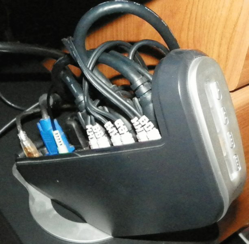
Figure 3.49 A KVM switch
Smart TV
The term smart TV was coined to describe a once budding class of monitors and televisions that have a built-in system for accessing network services. Today, the smart TV is almost as widespread as the networks to which they attach. The devices have gone from simply using the network to gain access to streaming online services to allowing users to browse the Web using remote controls or wireless keyboards and mice.
Smart TVs often have USB ports for the introduction of USB flash drives that contain entertainment media that the smart TV can recognize, and they offer a menu that allows the user to choose which file to access for playback on the TV. Many users combine the smart TV with a home media server to be able to stream movies and music across the wired or wireless LAN, which provides higher bit rates as compared to streaming similar media over the Internet.
Smart TVs are adept at installing themselves with minimal help from the home user, who may likely be a novice in the world of technical devices. At a minimum, however, the smart TV may require the user to choose from the available wireless networks within the range of the TV and to supply the chosen network’s password for access. Otherwise, a wired Ethernet connection must be supplied along with power and possibly some form of television input signal. Final configuration can include any of a variety of standard television and display settings as well as basic and advanced network preferences.
Set-Top Box
The term set-top box (STB) is used to describe any of a variety of thin rectangular chassis that can sit or stack on classic CRT televisions but that most often reside today on shelves or furniture. One of the most common STBs is the cable converter box, which has developed into the modern digital video recorder (DVR). Optical-disc players and burners, home-theater PCs, and similar devices secure the STB’s place in the combination input/output category.
Steps to install a set-top box are dependent on the type of STB in question. They range from choosing favorite and blocked channels to the same steps required to connect and configure a standard personal computer.
Summary
In this chapter, you learned about various types of expansion cards, the interfaces for which they are best known, and the peripherals to which they connect. The fact that some interfaces have gone through an evolution, changing in appearance and capabilities at times, was also presented. No discussion of expansion cards and interfaces would be complete without adding in the details of the cables needed, if any, to connect the cards to the peripherals; the discussion in this chapter is no exception.
This chapter also surveyed the details of peripherals from an output vs. input perspective, including specifics on the connections for display devices. Well-known input devices, such as the mouse and keyboard, and less conventional yet popular input devices were examined in this chapter. You also learned about the KVM switch, a device that allows you to share input and output devices among computers. The adapter cards highlighted in this chapter fall into four broad categories: video, multimedia, I/O, and communications.
Other output devices were presented, some with substantial detail while others that are covered in more detail elsewhere in this book were covered only briefly. Finally, you got a look at some of the most common hybrid devices that are capable of both input and output at once.
Exam Essentials
Familiarize yourself with installation and configuration of expansion cards. The variety of expansion cards available leads to the need to know the similarities and differences among them. For example, they all need to be inserted into the system using an expansion slot. They all perform a specific function or set of functions, based on their type, but not all cards are configured in the same way. Some require more configuration than others, while some require no installer interaction at all.
Recognize and understand different peripheral connectors and converters. Expansion cards and motherboards have external connectivity interfaces. The interfaces have connectors that adhere to some sort of standard for interconnecting with a cable or external device. Knowing these specific characteristics can help you differentiate among the capabilities of the interfaces available to you. Understanding when to use an adapter to convert one connector to another is crucial to achieving connectivity among differing interfaces.
Recognize and be able to describe display connectors specifically. Although a type of peripheral connector, display connectors are in a class all their own. Technologies continue to be developed to merge display and other peripheral functions, such as serial I/O, but the differences among the various display interfaces are substantial enough for these connectors to warrant their own category.
Know the characteristics of cables used for peripheral attachment. Whether the connection is internal or external to the computer system, each cable used has specific characteristics, no matter their resemblance to others. Some cables that look similar to others support higher speeds or longer distances. Some have power components, while others are completely passive in nature. Knowing the specific cables that go along with the expansion cards and their interfaces is extremely valuable and important.
Compare and contrast input devices. Although input devices vary widely in their functionality, they all provide external input to the computer. Familiarize yourself with the specifics of the devices mentioned in this chapter, differentiating them by their function and applicability to a particular need.
Be able to differentiate among input, output, and hybrid devices. The output-only devices listed and described in this chapter are less plentiful than the input devices. In fact, there are more combination input/output devices covered than output-only devices. Know the differences among them, and be able to explain why they fall into the category that they do.
Review Questions
The answers to the chapter review questions can be found in Appendix A.
-
You want to plug a keyboard into the back of a computer. You know that you need to plug the keyboard cable into a PS/2 port. Which style of port is the PS/2?
- RJ-11
- RJ-45
- DIN 5
- Mini-DIN 6
-
What is the maximum speed of USB 2.0 in Mbps?
- 1.5
- 12
- 60
- 480
-
Which of the following is both an input and an output device?
- Webcam
- Motion sensor
- Touchscreen
- Touchpad
-
What peripheral port type was originally developed by Apple and is currently regarded as the optimal interface for digital video transfers?
- DVD
- USB 2.0
- IEEE 1394
- IEEE 1284
-
What peripheral port type is expandable using a hub, operates at 1.5MBps, and is used to connect various devices (from printers to cameras) to PCs?
- DVD 1.0
- USB 1.1
- IEEE 1394
- IEEE 1284
-
Which peripheral port type was designed to transfer data at higher speeds over a D-sub interface?
- DVD
- USB
- IEEE 1394
- IEEE 1284
-
The surround sound mode known as 5.1 employs how many speakers when only one is used for each channel?
- One
- Five
- Six
- Seven
- Eight
-
Which of the following display interfaces is equivalent to DisplayPort with PCIe added in?
- Thunderbolt
- WHUXGA
- IEEE 1394c
- HDMI
-
Which of the following interfaces allows audio to be sent out over the same cabling infrastructure as video?
- VGA
- DVI
- HDMI
- Composite
-
How do you connect a DVI-A interface on a peripheral to a DVI-D interface on the computer?
- With a DVI-I cable.
- With a cable that is terminated on one end with a DVI-A connector and on the other end with a DVI-D connector.
- You wouldn’t interconnect those two interfaces.
- With a standard DVI cable.
-
What kind of device uses unique physical traits of the user to authenticate their access to a secure system or location?
- Barcode reader
- Biometric device
- Keyboard
- Touchscreen
-
Why might you use a KVM switch?
- You have multiple Ethernet devices that need to communicate with one another.
- You need to be able to switch the voltage supplied to a particular device.
- You have a printer that is not attached to the network but you want multiple computers to be able to print to it.
- You have more than one server and don’t want to buy certain external peripherals separately for each.
-
Which type of input device employs roughly the same connector as the original AT keyboard?
- Barcode reader
- PS/2 keyboard
- MIDI
- Touchscreen
-
What can you use to convert video to a format that can be uploaded to the Internet, among other things?
- A barcode reader
- A video capture card
- A TV tuner card
- A MIDI device
-
Which of the following is not an example of a connector for a standard peripheral input device?
- 1/8" jack
- Mini-DIN
- D-subminiature
- USB
-
Which category of adapters includes NICs?
- Multimedia
- I/O
- Communications
- Video
-
What category of adapter would you need to install to equip a system with one or more USB ports?
- Multimedia
- I/O
- Communications
- Video
-
What type of adapter has an RJ-11 jack built in?
- Modem
- Video
- Sound
- NIC
-
What type of pointing device features a ball and buttons on the top and a flat, steady surface on the bottom?
- Mouse
- Touchpad
- Trackball
- Trackpad
-
VGA-based video technologies use what type of signal between the adapter and monitor?
- Digital
- Analog
- Compressed
- Composite
Performance-Based Questions
You will encounter performance-based questions on the A+ exams. The questions on the exam require you to perform a specific task, and you will be graded on whether or not you were able to complete the task. The following requires you to think creatively in order to measure how well you understand this chapter's topics. You may or may not see similar questions on the actual A+ exams. To see how your answers compare to the authors᠙, refer to Appendix B.
-
Looking at the back of a computer, you see interfaces of the following colors and shapes:
- Gray, flat 4-pin
- Blue, DE15
- Green, mini-DIN 6
- Purple, mini-DIN 6
- Green, 3.5mm TRS
-
One by one, match the following external devices and functions to these interfaces:
- VGA
- USB
- Mouse
- Keyboard
- Speaker