
3
Ethernet Technology and Virtualization
In the world of networking, Ethernet is the predominant technology found within the local area networks (LANs) of organizations. While Ethernet is very common, network professionals need to be aware and have a strong understanding of various Ethernet technologies and standards that are used within the networking industry, as well as how these standards and technologies help professionals to improve their network design and performance.
In this chapter, you will learn about various types of network connections and media types used for wired communication within an organization. You will explore various wiring standards and the various characteristics of copper and fiber cabling, as well as their advantages and use cases. Furthermore, you will gain a solid understanding of cable management and termination points that are used by service providers and organizations to interconnect their networks. Lastly, you will learn about Ethernet and virtualization technologies.
In this chapter, we will cover the following topics:
- Types of connections
- Ethernet standards
- Virtual networking concepts
Let’s dive in!
Technical requirements
To follow along with the exercises in this chapter, please ensure that you have met the following hardware and software requirements:
- Windows 10 Enterprise: https://www.microsoft.com/en-us/evalcenter/evaluate-windows-10-enterprise
- Oracle VM VirtualBox: https://www.virtualbox.org/wiki/Downloads
- Oracle VM VirtualBox Extension Pack: https://www.virtualbox.org/wiki/Downloads
Types of connections
While working within the networking industry, you will commonly discover many organizations’ networks uses wired and wireless connections to interconnect their users’ devices to the network. Within environments with a lot of desktop computers and servers, wired connections are mostly implemented since the desktop computers are stationary and less likely to move from one location to another. On the other hand, servers are usually implemented within the server room and mounted onto a server rack and won’t be moved to a new location unless needed by the organization. Hence, there are a lot of wired connections, which allows network professionals to connect end devices to the network.
There are two main types of wired connections that are commonly used within organizations on their networks, as follows:
- Copper
- Fiber optic
Over the next few sub-sections, you will learn about the characteristics, advantages and disadvantages, and use cases of each type of network medium.
Copper cables
One of the most common types of network media you will find in many organizations and networks is copper cables. These are inexpensive network cables that are very easy to implement within buildings, office spaces, and homes. As an aspiring network professional, it’s important to understand the fundamentals of each type of cable used within the industry.
There are two types of copper cables that are used within networks:
- Unshielded Twisted Pair (UTP)
- Shielded Twisted Pair (STP)
UTP cables are very common and you will find them in almost any network within an organization and even Small Office/Home Office (SOHO) networks. These allow network professionals to connect users’ devices, such as computers and IP phones, to the network to access and share resources. The UTP cables are referred to as unshielded because the physical cable does not contain a protective coating to prevent the actual conductors from absorbing electromagnetic interference (EMI) from machinery and other components. When a device such as a computer wants to send a message to another device over a network, the Network Access layer of the Transmission Control Protocol/Internet Protocol (TCP/IP) networking model converts the message into an appropriate signal for the network media before placing the message onto the actual network.
Copper cables transmit electrical signals over the wire in short distances and networking devices can decode the signals into packets and data. As these electrical signals are transmitted along a copper wire, the conductors, which are the actual copper wires, can absorb EMI from nearby devices and other electrical wires. When this occurs, the bits that are being transmitted in the form of electrical signals along a copper wire (medium) between devices will become corrupted and the sender will need to retransmit any messages that are damaged or corrupted.
Additionally, copper networking cables as referred to as twisted pair cabling. Within each UTP cable, there’s a total of 8 individual wires that have a unique color coating. These wires are twisted in a total of 4 pairs to improve the resiliency against EMI from nearby devices and adjacent electrical wires.
The following figure shows a UTP cable:
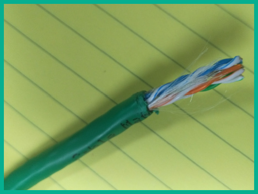
Figure 3.1 – UTP cable
While UTP cables are very susceptible to EMI, the twisting of the conductors (copper wires) reduces the likelihood of messages being corrupted. Keep in mind that while the cables are twisted within the outer jacket, it still does not stop EMI from being absorbed by the copper conductors. Therefore, it’s not recommended to implement UTP cables in areas or zones that contain a lot of machinery that emits EMI.
Another type of copper cable used within the networking industry is an STP cable. This is another type of twisted cable with the addition of protective shielding around the twisted conductors within the outer jacket.
The following figure shows an STP cable:
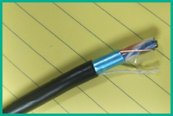
Figure 3.2 – STP cable
As shown in the preceding figure, the STP cable has shielding (a foil coating) around the twisted pair of wires. This protective shielding is used to prevent EMI from entering the copper conductors within the cable. Unlike UTP cables, which are inexpensive, STP cables are usually a bit more expensive because of the additional layer of protection within the cable’s design. Hence, network professionals commonly implement STP cables within environments that have a lot of EMI.
As you have learned, networking professionals always need to understand the need for implementing the appropriate type of cable within various types of environments. The outer jacket of both the UTP and STP cables are made using Polyvinyl Chloride (PVC), a material that releases toxic/harmful fumes to humans when burnt. These are known as non-plenum-rated cables. Sometimes, network professionals need to run network cabling within the plenum spaces of a building or office space. The plenum areas within an organization are the spaces that allow airflow to support heating and ventilation. Imagine if non-plenum-rated cables such as those that are made using PVC are installed within the ventilation air spaces, and these cables were to burn during a fire emergency within a building – the toxic fumes would be harmful to all employees and people within the organization.
Hence, it’s highly recommended to implement plenum-rated cables within the plenum spaces within buildings when needed. Depending on your country, it may be required by the building codes and regulations to support the safety of people within a building.
The following diagram shows an example of a plenum-rated cable:
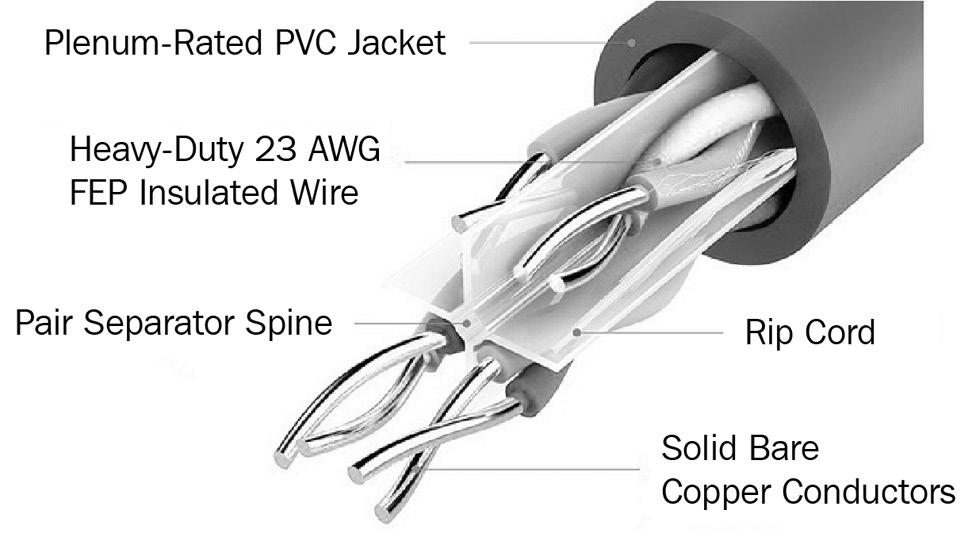
Figure 3.3 – Plenum-rated cable
As shown in the preceding diagram, plenum-rated cables contain a plenum-grade outer jacket to prevent fire from burning the conductors; there’s also a pair of separator spines to keep each pair of twisted cables separate from other pairs. As you can imagine, plenum-rated cables are more expensive compared to non-plenum-rated cables. Keep in mind that plenum-rated cables are less toxic when they are burnt during a fire and it’s important to properly plan which type of cables to use and how many are needed before starting a project.
Various types of copper cables are used to interconnect end devices to the network. The Telecommunication Industry Association (TIA) created a cabling standard that’s used by networking professionals within the industry. The TIA standard defines various categories for networking cables. These cables are described as a category (Cat) cable followed by a number. Each category defines how the cable can be applied to a network, its support speed, such as bandwidth, and the maximum length for data transmission.
The following is a list of various types of category cables that are commonly found within organizations:
- Cat 3: Supports speeds up to 10 Mbps with a maximum distance of 100 meters
- Cat 5: Supports speeds up to 100 Mbps with a maximum distance of 100 meters
- Cat 5e: Supports speeds up to 1 Gbps with a maximum distance of 100 meters
- Cat 6: Supports speeds up to 1 Gbps with a maximum distance of 100 meters
- Cat 6a: Supports speeds up to 1 Gbps and 10 Gbps with a maximum distance of 100 meters
- Cat 7: Supports speeds up to 1 Gbps and 10 Gbps with a maximum distance of 100 meters
- Cat 8: Supports speeds up to 40 Gbps with a maximum distance of 30 meters
While a network cable may specify a maximum distance, in reality, these copper cables experience attenuation as the electrical signal travels along the wire. Attenuation is the loss of signal as it travels along a medium from a source to a destination. Therefore, if you use a single 100-meter cable to interconnect two devices such as a computer and a switch, as one device sends a message to the other in the form of an electrical signal on the media (network cable), the electrical signal will experience attenuation as the signal get weaker as it travels further away from the sender.
The ends of the twisted pair cables are terminated by various types of Registered Jack (RJ) connectors. To terminate the ends of a CAT 3 cable, an RJ-11 connector is used on both ends of the cable. The RJ 11 connector contains 4 pins; these are commonly used on traditional landline telephone systems.
The following figure shows a CAT 3 cable with an RJ 11 connector on its end:
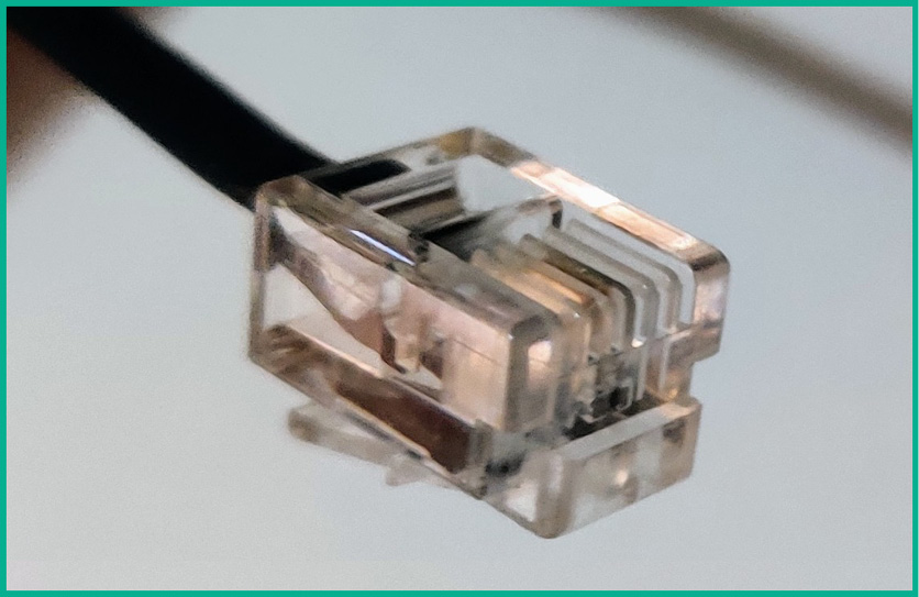
Figure 3.4 – Cat 3 with an RJ 11 connector
Additionally, the RJ 45 connector is an 8-pin connector that is used on most modern Ethernet cables, such as CAT 5 and above. The following figure shows an Ethernet cable with an RJ 45 connector:
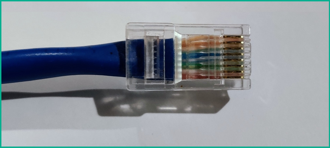
Figure 3.5 – Ethernet cable with an RJ 45 connector
The TIA-568 standard helps networking professionals and organizations maintain consistency within their networks. The TIA has created two cabling termination standards that indicate how each conductor within a cable is terminated to a corresponding pin within an RJ 45 connector. The following are the two cabling standards that are used within organizations:
- TIA-568A
- TIA-568B
The following diagram shows the TIA-568A termination standard for an RJ 45 connector:
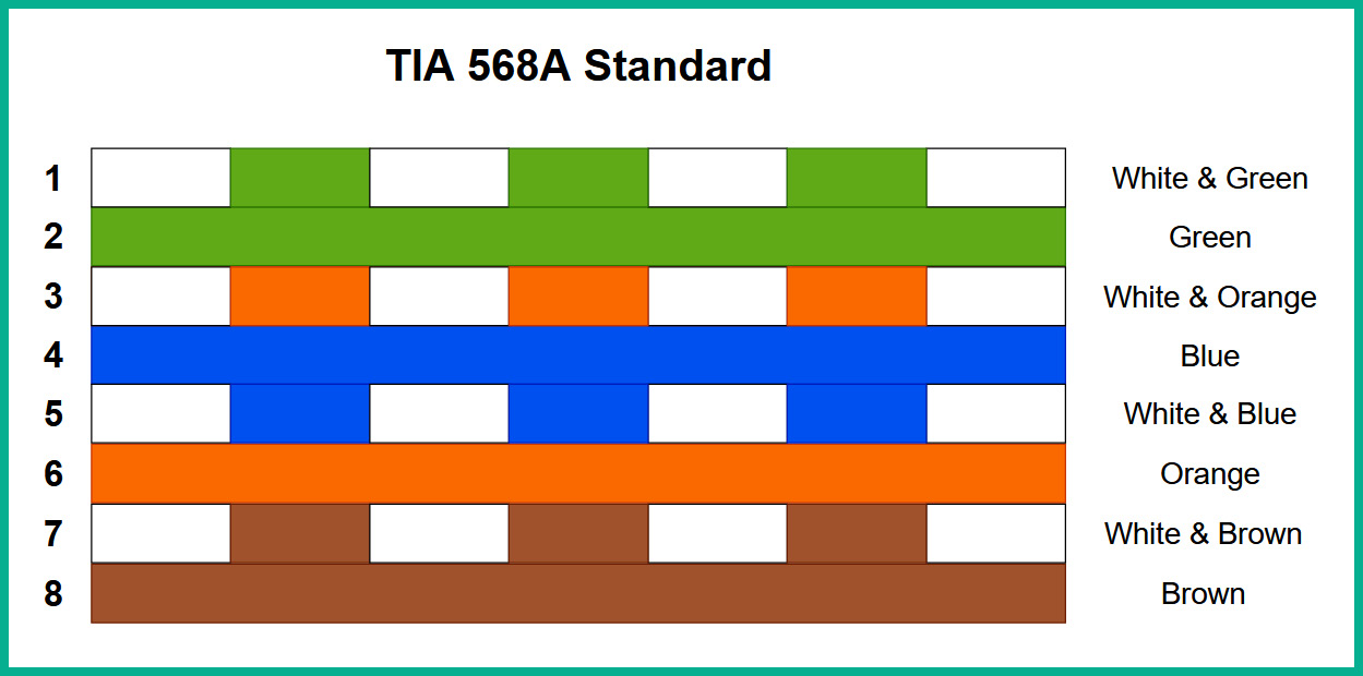
Figure 3.6 – TIA-568A standard
As shown in the preceding diagram, each conductor has a unique color code that is matched to a unique pin within the RJ 45 connector.
The following diagram shows the TIA-568B termination standard for an RJ 45 connector:
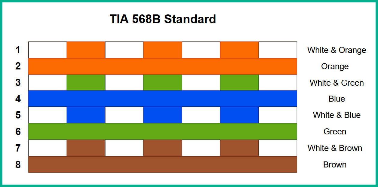
Figure 3.7 – TIA-568B standard
As shown in the preceding diagram, the termination of the pin layouts in the TIA-568B standard is a bit different from the TIA-568A standard. Here, the cables in pins 1, 2, 3, and 6 switch positions from TIA-568A to TIA-568B standards.
A straight-through cable is formed by terminating a twisted-pair cable run with the same pin-to-pair assignments on both ends. As an example, if the TIA-568B standard is used on one end of a cable, the same TIA-568B standard is used to terminate the other end. In this manner, each pin in a connector on one end of the cable corresponds to the same pin on the other end of the cable. A crossover cable, on the other hand, is formed by swapping the pair going to pins 1 and 2 with the pair to pins 3 and 6. This is equivalent to terminating one end according to the TIA-568A standard, and the other end according to the TIA-568B standard. This mixture of standards is significant because it swaps the pins used for transmission and reception on equipment, allowing two similar devices to communicate.
The following diagram shows a comparison of the TIA-568A and TIA-568B standards:
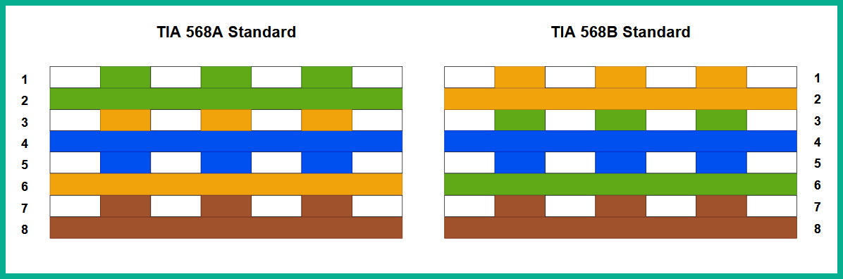
Figure 3.8 – Comparing the TIA-568 standards
Straight-through cables are commonly used to interconnect different types of devices together, while crossover cables are used to interconnect the same type of devices together. Therefore, straight-through cables (also called patch cables) are used to connect computers to switches or switches to routers, whereas crossover cables are used to connect switches to other switches, routers to other routers, computers to routers, and computers to computers. However, modern equipment often possesses a feature called Automatic Medium Dependent Interface Crossover (Auto MDI-X), which automatically detects that a crossover cable is required on a link and logically swaps the pins used for transmission or reception accordingly, allowing a straight-through cable to be used instead.
Another type of copper cable is coaxial. This type of cable usually has a foil coating around the copper core to protect it from EMI. Coaxial cables contain multiple layers of protection to prevent harm to the copper conductor at the core. This type of cable transmits its electrical signals through an inner core of either solid or stranded copper, or copper-clad steel. This inner conductor is surrounded by a layer of insulating material (usually plastic), which is itself surrounded by braided copper cable. This outer braided copper cable (which is usually grounded) serves to protect the inner core from EMI (keeping noise in the radio frequency domain out of the core) and signal leakage (keeping signals through the core inside of the coaxial cable). The inner insulating material (sometimes called a dielectric material) serves to separate the two conductors in the cable, while the outermost insulating sheath serves to cover and protect the outer braided jacket, and the entire cable by extension.
The following figure shows a coaxial cable:
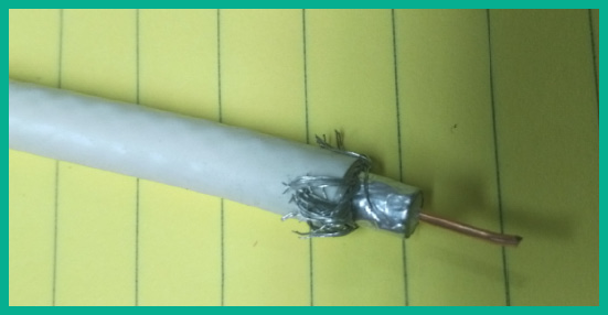
Figure 3.9 – Coaxial cable
Coaxial cables use the Radio Guide/Grade (RG) standard for their specification. In particular, the RG-59 legacy standard is used on older TVs and cable modems with a termination point of 75 Ohms. However, the newer RG-6 standard that is used on cable TV and broadband internet services has a termination point of 75 Ohms.
The following are the various layers of a coaxial cable, from the outer to inner layers:
- Protective coating: Made using PVC and protects the internal media from external elements and environmental factors
- Braided shielding: Prevents EMI from reaching the copper conductor
- Foil shielding: Prevents Radio Frequency Interference (RFI) from reaching the copper conductor
- Dielectric Insulator: An insulator to separate the copper conductor and the braided shielding, and to keep the copper conductor at the center of the coaxial cable
- Copper conductor: Used to transmit the electrical signals along the cable
The following three types of connectors are used on coaxial cables:
- F-pin connector
- Bayonet Neill-Concelman (BNC) connector
- T type connector, which is used to interconnect three coaxial cables together
One of the most common types of connectors used to terminate the end of a coaxial cable is the F-pin connector. The F-pin connector is used on coaxial cables, which are commonly attached to cable modems, televisions, and VCRs.
The following figure shows a coaxial cable with an F-pin connector to terminate the end:
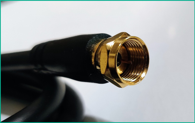
Figure 3.10 – F-connector on a coaxial cable
The BNC connector, named after both its locking mechanism type and its creators, is commonly used at the end of coaxial cables to transmit Radio Frequency (RF) signals for equipment such as televisions and radios. The BNC connectors are primarily made in 75 Ohms and 50 Ohms variants so that they can be used in cables with similar impedance. Mismatches between the connector and the cable results in attenuation of the RF signals across the link. BNC connectors are attached to coaxial cables with the aid of a crimper, while male and female connectors are attached by joining and turning them in a quarter rotation.
The following diagram shows a T-connector:
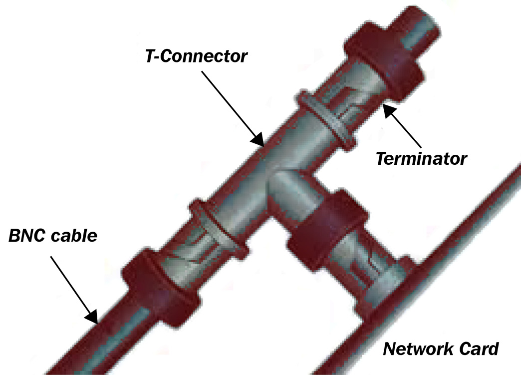
Figure 3.11 – T-connector
The following figure shows a BNC connector for a coaxial cable:
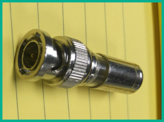
Figure 3.12 – BNC connector
Sometimes, you may need to connect a copper cable to a switch that supports only fiber optic connectors or vice versa. Using a media converter such as a copper-to-fiber converter will convert the electrical signals on the copper cable to light signals for a fiber optic cable, whereas a fiber-to-copper media converter is used to convert the light signals from a fiber optic cable to an electrical signal for a copper cable.
The following figure shows a coaxial to fiber media converter:

Figure 3.13 – Coaxial to fiber media converter
The preceding figure shows a Transition Network DS3/E3 COAX to Fiber Media Converter from Diversity-IT; credit goes to Diversity-IT for this figure.
Now that you are familiar with copper cables and components, next, you will learn about fiber optic cabling and its technologies.
Fiber optic cables
Although copper cables are still used in the vast majority of networks, fiber optic cables continue to replace copper cables in many sections of modern networks. These cables transmit data using pulses of light that are sent down a thin core of plastic or glass, which is surrounded by a material called cladding. This combination of core and cladding allows for the light to be transmitted through the process of either total internal reflection or continuous refraction of the light.
The following figure shows a fiber optic cable:
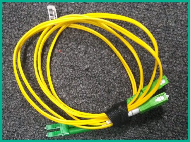
Figure 3.14 – Fiber optic cable
Compared to copper cables, fiber optic cables provide a lot of advantages, such as the following:
- Fiber optic cables allow faster throughput of data over the cable since fiber optic cables use Light Emitting Diodes (LED) or lasers to transmit data in the form of light rather than electrical signals. Also, photons travel at a higher speed than electrons, meaning that bits of data are delivered across the ends of fiber cables faster than in copper cables.
- Cables can be run for longer lengths since attenuation over fiber optic cables is lower than that of copper cables. Copper cables are typically rated for a maximum length of 100 meters, while fiber optic cables can run for many kilometers before needing a repeater.
- Fiber optic cables are immune to EMI.
However, there are a few drawbacks to using fiber optic cables within an organization:
- Fiber optic cables are more expensive compared to copper cables
- Fiber optic cables are very fragile and easy to break as the core is either glass or plastic
The following diagram shows the structure of a fiber optic cable:
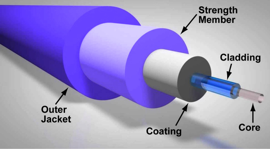
Figure 3.15 – Fiber optic cable structure
As shown in the preceding diagram, the fiber optic cable contains multiple layers of protection to prevent damage to the core. Each layer, such as the outer jacket, strength member, coating, and cladding, shields the core (glass or plastic) from external and environmental factors.
There are two major categories of fiber cables: single-mode and multimode. In the following subsections, you will explore the difference between these categories.
Single-mode fiber
In the context of fiber optic cables, a mode defines the method in which a wave travels through space. A single-mode fiber (SMF) optic cable is constructed to transmit only one mode of light through the fiber (in a direction parallel to the fiber). Thus, these cables consist of a core with a diameter that is quite small concerning the diameter of the cladding, since it only needs to accommodate a single mode of light. For example, one type of SMF cable is called 9/125 fiber, which means that the core is 9 micrometers or microns (μm) in diameter, while the cladding is 125 μm. Light through SMF can consist of multiple frequencies, but all of these frequencies follow a single path through the fiber.
SMF is usually used for fibers that need to span several kilometers in distance. Since all light waves follow a single mode, concepts such as modal dispersion (the spreading of light due to different modes) are not applicable, meaning that the attenuation of the light through the fiber is low and allows these links to span several kilometers without the need for an optical repeater. The light sources for SMF are usually lasers. Due to this requirement for laser light that can align well with the small diameter of SMF, transceivers (transmitters and receivers at either end of the fibers) are often more expensive than their multimode fiber (MMF) counterparts. SMF often operates using wavelengths of 1,310 nm or 1,550 nm, and the cable coating is often colored yellow.
Multimode fiber
MMF cables are constructed with much larger diameters than their SMF counterparts. For example, one common type of MMF is 62.5/125, meaning that the cable has a diameter of 62.5 μm, compared to the 9 μm of some SMF cables. This wider core allows multiple modes of light to propagate through the fiber, giving rise to additional losses due to phenomena such as modal dispersion, and limiting the maximum link length to much lower distances than SMF.
However, because of the wider core diameter, less precise transceivers can be used, allowing the cost of MMF systems to be generally lower than equivalent SMF systems. As an example, MMF transceivers may be constructed using less expensive LEDs instead of lasers as light sources. Therefore, network professionals need to weigh the cost of their fiber systems with their expected link distances appropriately, and determine whether the extra cost of SMF systems is necessary for the links that they require, or whether MMF would suffice for their situation.
Fiber connectors
The Lucent Connector (LC) is a type of fiber connector that was created by the Lucent Corporation. The connectors consist of a small plastic latch, similar to an RJ 45 jack, which helps secure the fiber connector to the port, and a 1.25 mm ferrule, which is used to align the fiber optic cable with the connector. Because of this small ferrule size, the LC connector is a small form factor connector, making it suitable for high-density fiber deployments such as in data centers.
The Straight Tip (ST) or bayonet connectors are a type of fiber connector that was created by AT&T. These types of connectors were popular in the late 1980s and 1990s, and consist of a larger ferrule (2.5 mm) and a twist-type, spring-loaded, cylindrical, nickel-plated, or stainless steel bayonet connector for locking. Its uses have declined in the last few years because other connectors (such as LC connectors) are less expensive and easier to connect and disconnect.
Subscriber Connectors (SCs), also known as Square Connectors or Standard Connectors, are connectors that were developed by Nippon Telegraph and Telephone (NTT). They are push-pull square-shaped connectors with 2.5 mm, spring-loaded, ceramic ferrule, and snap-in connector latches. They are easy to disconnect/reconnect and can be found in many network installations.
Mechanical Transfer Registered Jack (MT-RJ), also known as Media Termination Recommended Jack, are small, duplex fiber connectors, with both fibers terminating on a single 2.45 x 4.4 mm ferrule. They are roughly half the size of SCs and are easy to connect/disconnect from their ports using plastic latches, similar to RJ 45 connectors. Two pins, located on transceivers, allow easy alignment of the connector.
The following diagram shows various fiber connectors:
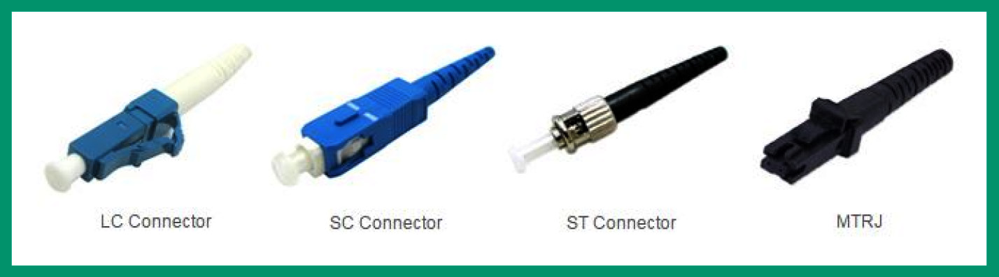
Figure 3.16 – Fiber connectors
As shown in the preceding diagram, each fiber connector has a unique form factor. Credit goes to AD-net Technology CO., LTD for their image.
Fiber transceivers
A transceiver is a component that is required to be inserted into a cage or slot on certain pieces of networking equipment, such as a switch, to provide an interface for certain types of copper or fiber cable to connect.
The following are common fiber transceivers:
- Gigabit interface converter (GBIC)
- Small form-factor pluggable (SFP)
- Enhanced small form-factor pluggable (SFP+)
- Quad small form-factor pluggable (QSFP)
- Enhanced quad small form-factor pluggable (QSFP+)
GBIC is a hot-swappable (can be removed and reinserted while equipment is powered on) transceiver that introduced the concept of removable transceivers, as opposed to fixed physical ports on networking devices, allowing for more flexibility in network links. Due to the appeal of GBICs, modern networking equipment requires transceivers (combined transmitter/receiver devices) on many ports to provide interfaces for different types of copper and fiber optic connectors, and cables to connect to the equipment.
The following figure shows a GBIC module from FiberStore:
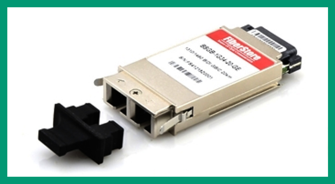
Figure 3.17 – GBIC module
SFP devices are compact, hot-swappable devices that are extremely common in modern networks, facilitating data rates of 1-2.5 Gbps through LC connectors (using both MMF and SMF) and data rates of 1 Gbps for twisted pair copper cables (using RJ 45 connectors). SFPs have largely replaced GBICs because of their smaller size. For fiber SFPs, transceivers exist to facilitate link lengths from several hundred meters to several kilometers, while copper SFPs are usually rated for a maximum of 100 m.
The following figure shows an SFP module from FiberStore:
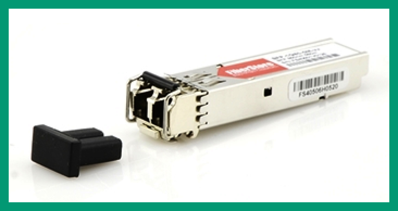
Figure 3.18 – SFP module
SFP+ supports higher data rates, and some equipment supports SFP+ transceivers, which are commonly used for 10 Gbps links using SMF or MMF cables. Copper SFP+ modules, which provide 10 Gbps speeds over twisted pair cables, also exist, but they are less common and more expensive.
QSFP and QSFP+ support even higher data rates; some equipment supports QSFP or QSFP+, which provide capacities of 4 Gbps and 40 Gbps, respectively. As their names suggest, they are constructed from four individual SFP or SFP+ channels, which are aggregated to provide four times the speed with significant space savings on devices, allowing for more dense deployments.
The following figure shows a QSFP module for a Brocade device:
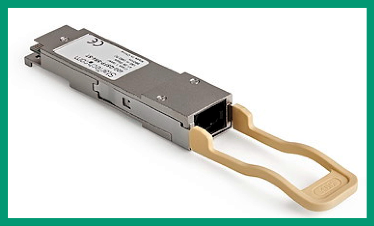
Figure 3.19 – QSFP module
Credit for the preceding figure goes to StarTech.
Cable management
As an organization grows in terms of the number of employees, so does the network infrastructure as it needs to support additional users, devices, and services. The server or networking closets are special rooms within an organization that contain many servers and networking devices with cables running to all other areas within the building. As you can imagine, as more users and devices connect to the organization’s network, a lot more cables will be needed. If networking professionals do not apply best practices and enforce cable management within their organization, networking cables will be very untidy within the server and network closet, as well as in other areas of the building. Poor practices in cable management can increase the time network professionals take to resolve network cabling issues within an organization.
Implementing best practices with cable management allows networking professionals and organizations to use a systematic approach to organizing and managing all the networking cables within an organization. Additionally, it helps networking professionals quickly and easily identify individual networking cables when troubleshooting issues on the network. Furthermore, maintaining a tidy workspace and environment also reduces the likelihood of networking cables being damaged.
Cable termination points
There’s a wide range of termination points in the context of networking. Cables from different telecommunication and internet service providers often terminate at a particular location in a network, while cables on downlinks to a customer’s network may terminate at a different location. There are two common network termination blocks within many organizations, as follows:
- 66 block
- 110 block
66 and 110 blocks are two types of punch-down blocks that are commonly used to connect copper wires in networking systems. In a punch-down block, individual copper wires are pressed down into open-ended slots using a punch-down tool, causing two sharp metal blades in the slot to cut into the insulation of the wire, thus achieving electrical connectivity.
The following figure shows a 66 block from Major Custom Cable, Inc.:
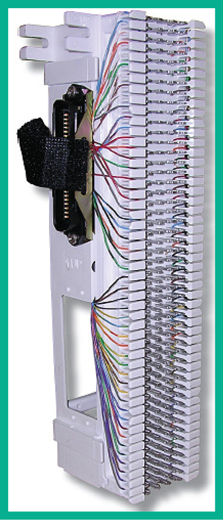
Figure 3.20 – 66 block
Important note
Krone is a European alternative to the traditional 110 block, while Bix is an alternative to the 66 block.
The 66 block is so named because of its model number, but it provides slots to accommodate 25 pairs or 50 split pairs of Cat 3 copper wire. The 66 blocks are often used for voice/telephone cabling within an organization.
The following figure shows a 110 block:
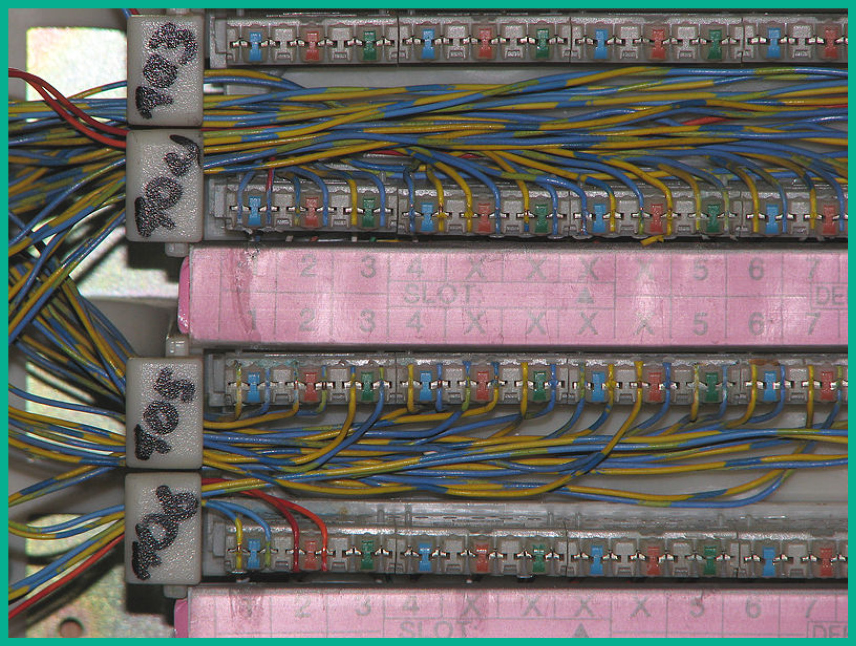
Figure 3.21 – 110 block
The 110 blocks are an upgraded version of the 66 blocks, providing increased slot density and meeting newer standards of twisted-pair copper cables, thus allowing these blocks to accommodate higher bandwidth links. The 110 blocks can often accommodate hundreds of Cat 5 and beyond copper cables.
Patch panels
In the context of networking, patch panels are pieces of equipment that facilitate the Physical Layer connections between links. Different patch panel types allow connections to be made between different types of cables. For example, fiber optic patch panels (or fiber distribution panels) provide ports for different types of fiber connectors (LC, SC, and so on), allowing connectivity to and between different strands of fiber cables. These panels are frequently used at locations where trunk cables (cables containing many individual copper or fiber cables) enter premises, allowing these individual cables to be terminated in a manner that is easy to manage on the premises. Patch (or jumper) cables are usually used to connect equipment to the ports of these patch panels or to connect between ports on the panels.
The patch panel allows networking professionals to connect wall jacks within the office space with a drop cable to the patch panel within the network closet. The patch panel then connects to a switch because the device, such as a computer, is not directly connected to the switch. This simplifies the configuration that’s done on the switch.
Important note
The fiber distribution panel uses the same concept as the copper patch panel. A fiber distribution panel has extra space to allow the fiber cables to be wrapped in a circular/loop format to prevent the fiber core from bending.
Having completed this section, you have covered the fundamentals of various cabling connections and standards that are commonly found within the network industry. In the next section, you will discover various types of Ethernet standards that every networking professional needs to know.
Ethernet standards
Ethernet is the de facto technology that is used on all modern LANs within organizations. Ethernet helps both end devices and networking devices to communicate over both a wired and wireless network infrastructure using various networking protocols and standards. As you may recall, protocols are simply the rules, procedures, and methodologies that are used to govern how information and data are sent across a network between systems.
As with all technologies in the world, various Ethernet standards are maintained by the Institute of Electrical and Electronics Engineers (IEEE) that define how communication occurs across a wired network, whether the network media is copper or fiber optic cables. The IEEE 802.3 standard is used on LANs for communication and there are many variants of this standard. Each variant specifies the type of media used for communication between devices and the support speed/bandwidth of the interface of a device.
Since the IEEE 802.3 standard was developed many years ago, the standard has had many new revisions over time to support newer features and capabilities. These various IEEE 802.3 standards are implemented within both copper and fiber optic network cabling, which follows the BASE standard.
The BASE standard helps networking professionals identify the specific characteristics of a cable, such as the following:
- Transmission speed: Defines the support bandwidth of the media such as 10 Mbps, 100 Mbps, 1,000 Mbps (1 Gbps), and 40 Gbps or greater
- Signaling method: BASE band signaling is the default signaling method that allows devices on a LAN to use the entire supported bandwidth of a media to transmit data between a source and destination while using a single data channel
- Media type: The media type of the networking cable, such as copper or fiber cable
The following is a list of common Ethernet standards for copper media:
- 10BASE-T: Known as IEEE 802.3i, it supports Ethernet speeds of 10 Mbps with a signaling method of BASE that uses Twisted Pair (T) media (Cat 3) with a maximum distance of 100 meters.
- 100BASE-TX: Known as IEEE 802.3u, it supports Fast Ethernet speeds of 100 Mbps with a signaling method of BASE that uses a Pairs of Twisted Pairs (TX) media (Cat 5) with a maximum distance of 100 meters.
- 1000BASE-T: Known as IEEE 802.3ab, it supports a Gigabit Ethernet speed of 1,000 Mbps or 1 Gbps with a signaling method of BASE that uses Twisted Pair (T) media (Cat 6) with a maximum distance of 100 meters.
- 10GBASE-T: Known as IEEE 802.3an, its supports 10 Gbps with a signaling method of BASE that uses Twisted Pair (T) media (Cat 6, Cat 6a, and Cat 7). The Cat 6 cables have a reduced distance of 55 meters when working with the 10GBASE-T standard with supported distances of 55 meters for Cat 6, 100 meters for Cat 6a, and 100 meters for Cat 7.
- 40GBASE-T: Known as IEEE 802.3bq, this supports 40 Gbps with a signaling method of BASE which that Twisted Pair (T) media (Cat 8) with a maximum distance of 30 meters.
The following table shows a summary of Ethernet standards for copper cables:
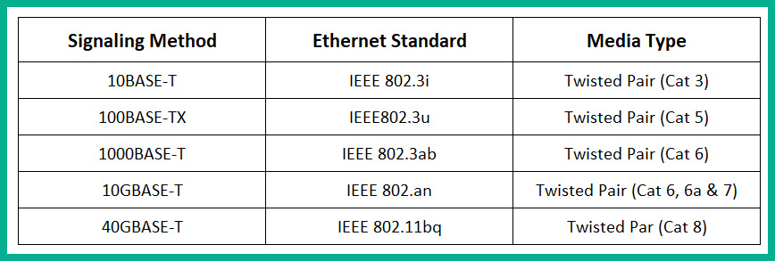
Figure 3.22 – Ethernet standards for copper cables
The Ethernet standard (IEEE 802.3) supports two environments: shared or switched mediums. The shared medium describes an environment in which all devices contend with one another for a spot of the network to communicate without being disrupted by other devices. This contention between devices can be solved, but on Ethernet networks that use copper cables, whenever a device such as a computer wants to send a message, it will attempt to access the network via the media and transmit the message across the network. In reality, there are usually multiple devices on the same network that also want to transmit their message at the same time. However, only one device can transmit at a time. This creates a content-based network where multiple devices are trying to access the network simultaneously to send their messages over the wire.
To solve this problem on a content-based network, the Carrier Sense Multiple Access/Collision Detection (CSMA/CD) methodology can be used. It allows only one device to transmit at a time on a wired Ethernet network. Before a sender transmits a message, it will check the media to determine if there is an existing electrical signal. If a signal is detected on the media, the sender will not transmit the message and re-check after some time to determine whether a signal still exists on the media. If no signal is detected on the media, the sender will transmit its message over the network to the destination host. However, without CSMA/CD, if two devices transmit at the same time on a content-based network, a collision occurs, causing the signals from the two senders to collide and become corrupted.
The following diagram shows a flow of actions that occur in CSMA/CD on a wired network:
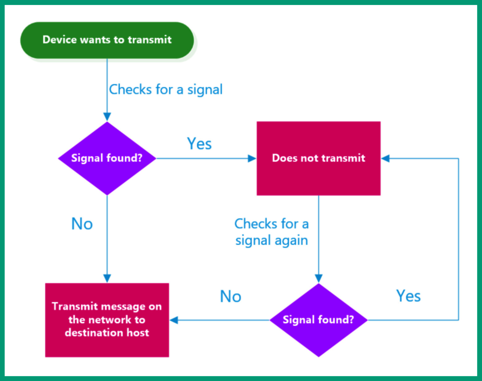
Figure 3.23 – CSMA/CD flowchart
The following is a list of common Ethernet standards for fiber optic media:
- 100BASE-FX: Known as IEEE 802.3u, this supports Fast Ethernet speeds of 100 Mbps on long-range Multimode Fiber (MMF)
- 100BASE-SX: Known as IEEE 802.3u, this supports Fast Ethernet speeds of 100 Mbps on short-range MMF
- 1000BASE-SX: Known as IEEE 802.3z, this supports Gigabit Ethernet speeds of 1,000 Mbps or 1 Gbps on short-range MMF
- 1000BASE-LX: Known as IEEE 802.3z, this supports Gigabit Ethernet speeds of 1,000 Mbps or 1 Gbps on long-range Single-Mode Fiber (SMF)
- 10GBASE-SR: Known as IEEE 802.3ae, this supports 10 Gigabit Ethernet speeds on short-range MMF
- 10GBASE-LR: Known as IEEE 802.3ae, this supports 10 Gigabit Ethernet speeds on long-range SMF
The following table shows a summary of Ethernet standards for fiber optic cables:
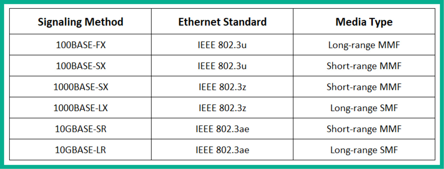
Figure 3.24 – Ethernet standards for fiber optic cables
Having completed this section, you have explored various types of Ethernet standards that are common within the industry and are found on networking cables and interfaces on devices. In the next section, you will explore virtualization technologies.
Virtual network concepts
Long ago, whenever IT professionals set up a server within their organization, the server operating system was installed directly on the storage device, such as the Hard Disk Drive (HDD). If you wanted to install another operating system on the same HDD, you would need to create a logical partition on the HDD and install the second operating system on the new partition. However, when powering on the physical server, only one operating system can be booted in the memory of the server. While running a single operating system at a time on a computer or server, the operating system has full access to all the hardware-based components, such as the processor, memory modules, storage drives, and so on. This allows the operating system to operate to its fullest potential and leverage all the available computing power to perform tasks and calculations.
However, an operating system does not always utilize hardware-based components all the time. There are many times when an operating system on a device such as a laptop, server, or even a smartphone will idle and use the least resources when there are no tasks or operations to perform. Imagine installing Windows Server 2022 on a very powerful server with a lot of memory, a high-end processor, and a lot of storage capacity but the operating system is using an average of 5-10% of the processor or less than 25% of the memory daily. As a result, there are a lot of unutilized computing resources on the server but the operating system is not leveraging it due to fewer resource-intensive applications and services that are running on the device. This is known as server sprawl.
The following screenshot shows the Task Manager on a Windows device that is under-utilized:
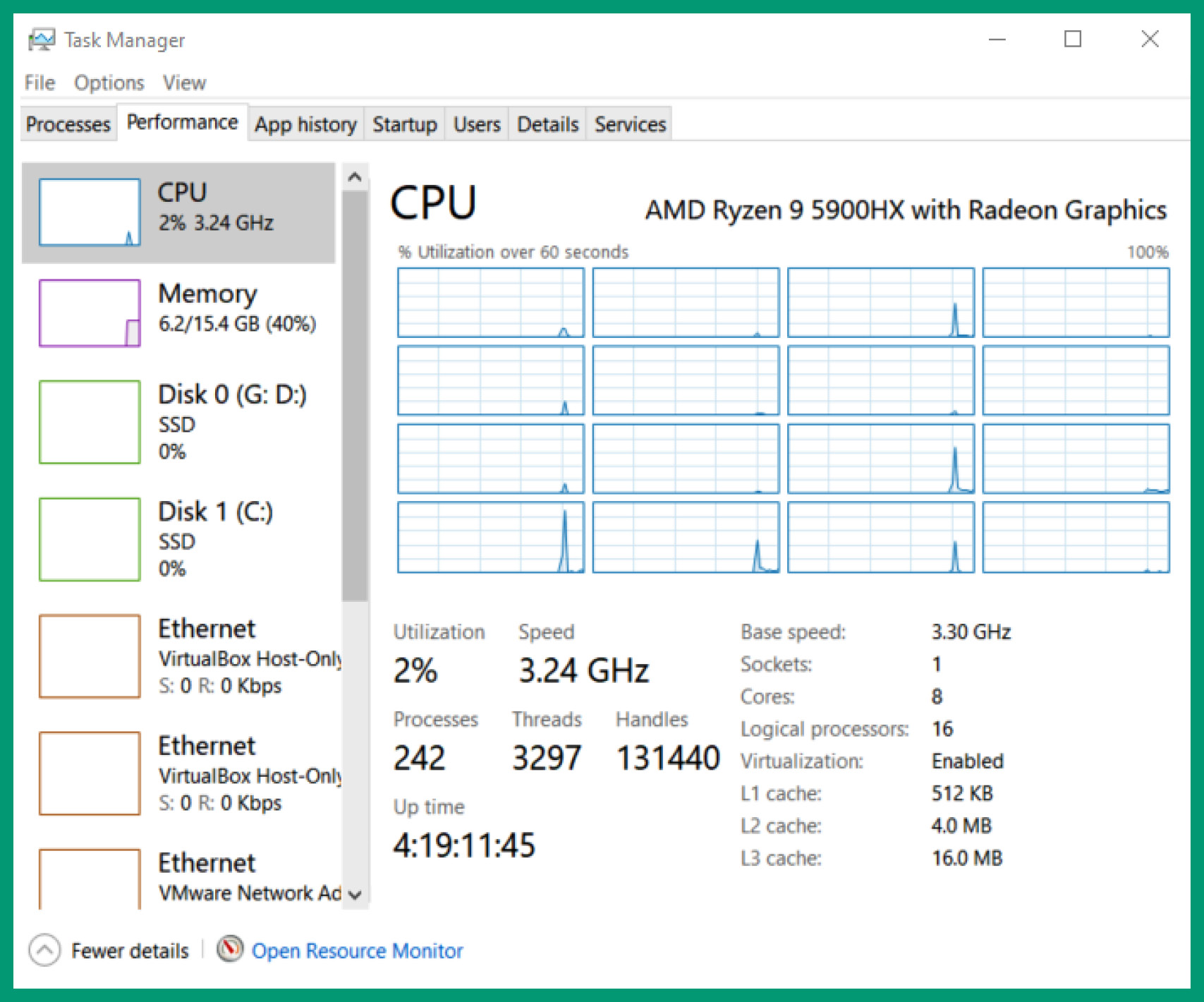
Figure 3.25 – Task Manager
What if you can install and run multiple operating systems at the same time on the same device? The legacy method would create a partition for each bootable operating system, but this method would allow only one operating system to run at a time. However, using a hypervisor application allows IT professionals to virtualize all the hardware-based components of a physical computer or server to allow virtual machines to be created.
Hypervisors
A hypervisor is an application that allows IT professionals to virtualize all the hardware-based components on a computer, such as its processor, memory, storage drives, network adapters, sound and video cards, optical drives, and even USB controllers. The hypervisor allows us to create a virtual environment to install guest operating systems on create a virtual machine. The hypervisor ensures the virtual environment is created to support the guest operating system, so a guest operating system will think it’s running on physically supported hardware components. As an example, imagine running the Android mobile operating system as a virtual machine within a virtual environment on top of a Windows operating system. The hypervisor ensures the virtual hardware components meet the specification to support the guest operating system, which is the Android mobile operating system.
When creating a virtual machine, the user, such as yourself, can customize each virtual machine environment and assign the number of processor cores, memory, and even storage allocation to each virtual machine. This technique allows IT professionals to run multiple virtual machines at the same time on a single physical computer or server so long as the hardware-based resources are fairly allocated to each running virtual machine.
Using virtualization technologies within organizations allows companies to reduce the number of physical servers within their buildings. As a result, fewer servers will reduce the expenditure cost of maintaining the components within each physical server. Furthermore, it will reduce the amount of space needed to store physical servers in the organization as one physical server can be running multiple virtual servers at the same time. Additionally, virtualization can help reduce the power consumption within the server room since there are fewer physical servers needed. This is because virtualization allows legacy operating systems to run on hypervisors.
Important note
The operating system that is installed within a virtual machine is referred to as the guest operating system, whereas the operating system that is installed on the storage device of a server, such as the hard drive, and booted into memory is referred to as the host operating system.
There are two types of hypervisors within the industry and each has a separate deployment model:
- Type 1 hypervisor
- Type 2 hypervisor
The Type 1 hypervisor is sometimes called a bare-metal hypervisor because it is installed directly on the hardware, such as the storage device, and boots into the memory of the server. This type of hypervisor has direct access to all hardware-based components on the server. As a result, each virtual machine has direct access to the hardware, so each virtual machine can operate more efficiently.
The following diagram shows the Type 1 hypervisor deployment model:
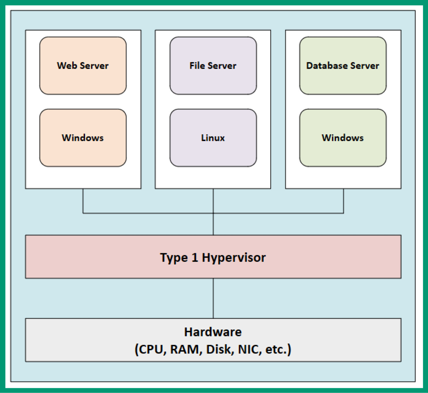
Figure 3.26 – Type 1 hypervisor
As shown in the preceding diagram, there’s no host operating system installed on the storage that will run on top of the hardware-based components. When the server is powered on, the Type 1 hypervisor application will load from the storage drive into memory and control all the hardware-based components, allowing the user to create and manage virtual machines.
Type 1 hypervisors are good for physical servers that are stationary. When installing a Type 1 hypervisor onto a physical server, a static IP address is assigned to ensure IT professionals can manage the hypervisor and all its features over a network.
Important note
Type 1 hypervisors are good in a data center setting. They can replace numerous physical servers by virtualizing several high-end server operating systems onto one physical server. All networking can be abstracted so that static IP addresses can be assigned to each VM. Furthermore, the hypervisor allows for centralized management of multiple VMs.
The following screenshot shows the user interface of VMware ESXi, a Type 1 hypervisor:
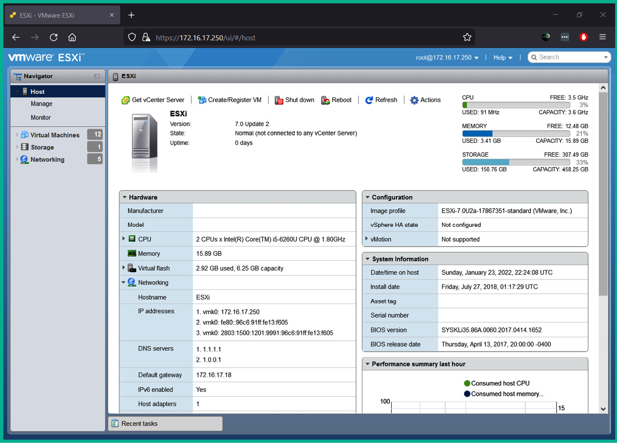
Figure 3.27 – VMware ESXi user interface
As shown in the preceding screenshot, VMware ESXi has a web-based user interface that allows you to easily manage a network. There are many Type 1 hypervisors available from trusted providers on the internet; some are commercial and others are free.
The following is a list of well-known free Type 1 hypervisors:
- VMware ESXi: https://www.vmware.com/products/esxi-and-esx.html
- Proxmox: https://www.proxmox.com
- XCP-ng: https://xcp-ng.org
While Type 1 hypervisors are amazing, there are not suitable for laptops since they are portable and have less powerful processing capabilities. Often, Type 2 hypervisors are installed on laptops or desktop computers. Installing a Type 1 hypervisor on a laptop is possible but accessing the user management interface will not be feasible.
The Type 2 hypervisor is an application that runs on top of an existing host operating system such as Microsoft Windows, Apple macOS, or Linux. This deployment does not allow the hypervisor application to interact directly with the hardware-based components of the computer or server, unlike the Type 1 hypervisor. However, the host operating system still utilizes the hardware resources to function and perform operations as needed; any remaining hardware-based resources are made available to the hypervisor for the virtual machines.
The following diagram shows the deployment of a Type 2 hypervisor:
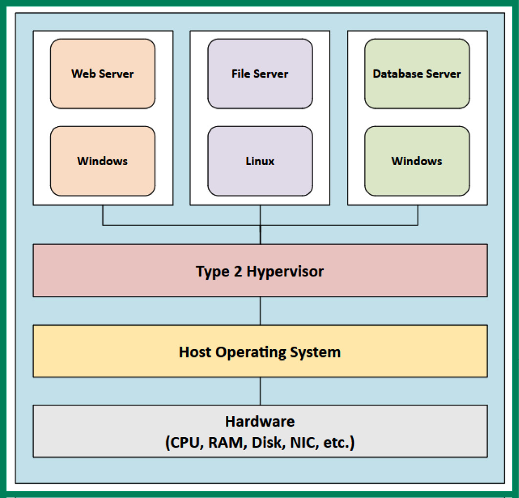
Figure 3.28 – Type 2 hypervisor
As shown in the preceding diagram, the host operating system runs on top of the hardware-based resources of the computer and uses any computing resources it needs to operate and perform tasks; the remaining resources are available to the virtual machines through the hypervisor application.
The following is a list of popular commercial and free Type 2 hypervisors:
- VMware Workstation Pro: https://www.vmware.com/products/workstation-pro.html
- VMware Player: https://www.vmware.com/products/workstation-player.html
- Oracle VM VirtualBox: https://www.virtualbox.org/
- Parallels: https://www.parallels.com
Using a Type 2 hypervisor on a computer or server allows you to run your host operating system and multiple virtual machines at the same time. Each virtual machine is an operating system in a virtual, isolated environment. Therefore, if one virtual machine is compromised by malware, the other virtual machines and the host operating system are not affected. However, if the virtual machines are networked to each other and the host operating system, the malware can spread through the virtual network within the hypervisor to other systems.
Virtual networking components
Creating a virtual machine can be very interesting and a bit exciting, especially if your duties are similar to those of a virtualization or cloud engineer. However, as aspiring network professionals, we must not forget that our network infrastructure also needs to be able to support a high amount of traffic, scalability, fault tolerance, and redundancy. As mentioned previously, one of the main benefits of virtualizing servers is being able to reduce the physical storage space for equipment such as servers and save on purchasing dedicated appliances. This concept also applies to networking devices such as switches and routers, and security appliances such as firewalls.
Network function virtualization
On a traditional network, you will commonly discover that there are many physical networking switches and routers that are used to interconnect end devices and other networks. Additionally, you’ll see physical security devices such as firewalls on the perimeter networks of organizations to filter both inbound and outbound network traffic and prevent traffic.
Nowadays, networking professionals use a concept known as Network Function Virtualization (NFV), which allows organizations to implement virtual networking devices within a hypervisor that provides the same functionality, features, and services as traditional physical devices. Imagine an organization running its security appliances such as a firewall and networking devices such as routers and switches within a hypervisor on a physical server with other virtual machines.
NFV provides the same major benefits of using virtualization within an organization, such as the following:
- With networking devices running in a virtualization environment, there’s no need to upgrade the hardware components of a physical device
- Multiple networking and security appliances can be running at the same time on a server, which reduces the need for physical space traditional physical device needs
- Reduces the overall power consumption as multiple virtual devices are operating on a single server
- There’s no need for specific hardware components for a virtual networking device as the hypervisor ensures the virtual environment is suitable
A virtual switch has the same function and capabilities as a hardware-based physical network switch; the difference is the virtual switch operating system is installed on a hypervisor that is running on a physical server on the network. Networking professionals can configure a virtual switch to provide the same functionalities and services as a physical switch on the network. Similarly, virtual routers can perform routing and IP services to a network, as would a physical router on a traditional network. The Cisco Cloud Services Router (CSR) 1000V is a virtual router from Cisco that allows networking professionals to be implemented on a hypervisor. The Cisco ASAv is a virtual firewall that can be implemented by organizations on their private cloud infrastructure and the public cloud on various cloud providers’ infrastructure.
Virtual network interface card
A hypervisor allows multiple virtual machines to run at the same time on a single physical computer or server device. Each virtual machine can be configured with unique networking configurations, such as allowing internet access to a virtual machine, placing a virtual machine within an isolated network, creating a network between the virtual machine and the host operating system only, and allowing a virtual machine to connect to the physical network or sharing the internet service through the host operating system.
Each virtual machine within a hypervisor has a Virtual Network Interface Card (vNIC), which allows the virtual machine to access a network. The vNIC on a virtual machine has the same features and capabilities as a physical NIC installed on a regular computer or server. The only difference is that the vNIC can be used to set up network connections on and between virtual machines on a hypervisor application.
The following diagram shows virtual machines with vNICs:
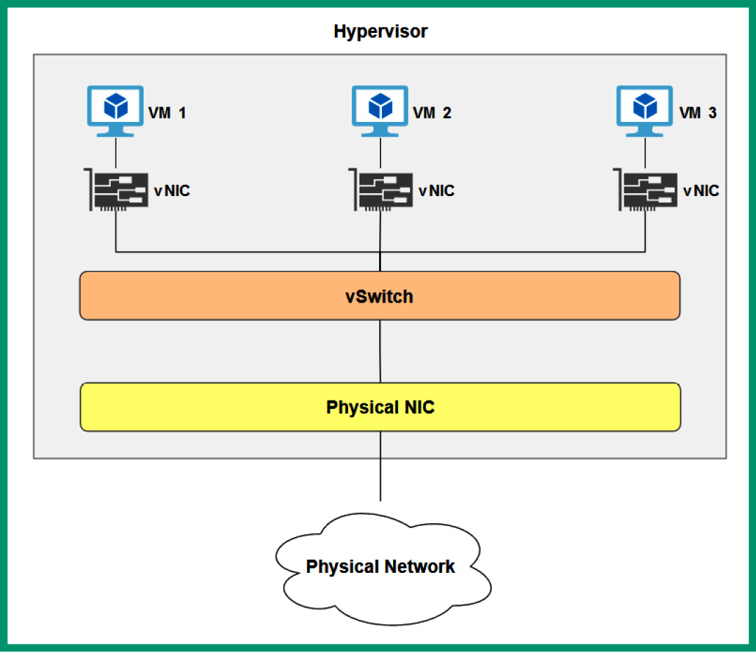
Figure 3.29 – vNICs on virtual machines
As shown in the preceding diagram, each virtual machine within the hypervisor has a vNIC, which allows them to access the host machine, other VMs on the host, other VMs on other hosts, other hosts on the network, or the internet, depending on the configuration with other virtual machines within the same hypervisor using a vSwitch. A virtual machine can have multiple vNICs installed to allow the virtual machine to access multiple networks at the same time.
vSwitch
A vSwitch has the same features as a physical switch, but the difference is that the vSwitch exists within a hypervisor, allowing multiple virtual machines to connect using their vNICs. Many hypervisor applications, such as VMware ESXi, provide this feature to allow network professionals to create a vSwitch that can serve many purposes. Let’s imagine you want to create a virtualized network where your virtual machines are within the same IP network. Therefore, creating a vSwitch and configuring the virtual machines’ vNICs to access the same vSwitch will create the desired effect.
The following screenshot shows a vSwitch within VMware ESXi:
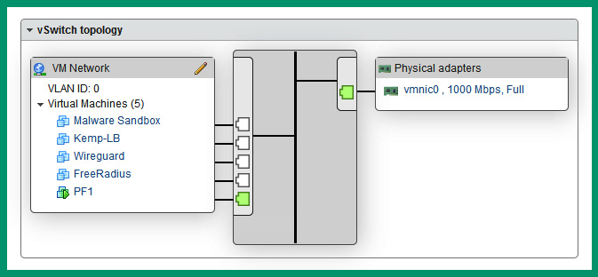
Figure 3.30 – vSwitch
As shown in the preceding screenshot, five virtual machines are connected to the same vSwitch, and the vSwitch is connected to the physical NIC on the server to provide access to the physical network within the organization.
Lab – creating a virtual machine
In this hands-on exercise, you will learn how to create a virtual machine on your computer using Oracle VM VirtualBox as the preferred hypervisor application. Before getting started with this exercise, the following are some important requirements:
- Ensure your processor on your computer supports VT-x/AMD-V virtualization features
- Ensure the virtualization features are enabled on your processor via the BIOS/UEFI
- You will need at least 2 GB of available memory and at least 20 GB of available space on your storage drive
Once you’re all set, please use the following instructions to get started.
Part 1 – creating the virtual environment
- First, you will need to download the Oracle VM VirtualBox hypervisor application by going to https://www.virtualbox.org/wiki/Downloads and choosing a software package based on the host operating system on your computer:
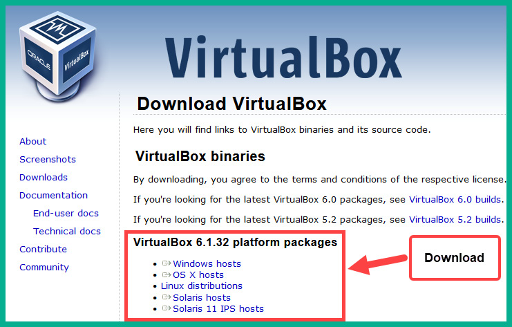
Figure 3.31 – Oracle VM VirtualBox download page
- Next, on the same download page, download VirtualBox 6.1.32 Oracle VM VirtualBox Extension Pack onto your computer. This Extension Pack provides additional features to the hypervisor, which may be required later in this book:
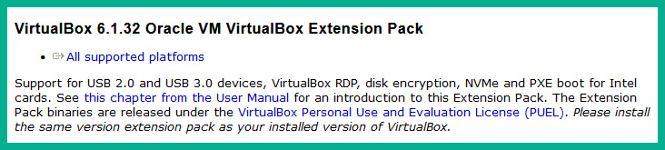
Figure 3.32 – Oracle VM VirtualBox Extension Pack
- Next, you will need to install the Oracle VM VirtualBox platform package that you downloaded in Step 1. During the installation process, use the default configurations and settings provided by the installer.
- Next, to install Oracle VM VirtualBox Extension Pack, right-click on the extension pack and choose Open With | VirtualBox Manager to begin the installation. Ensure you accept the user agreement to continue the installation process:
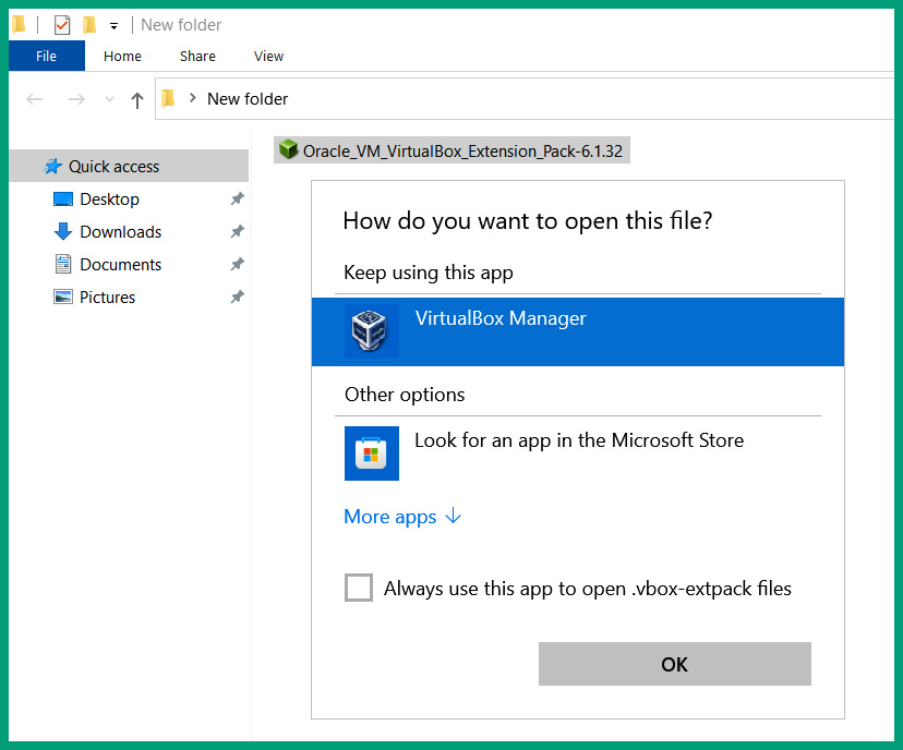
Figure 3.33 – VirtualBox extension pack
- Next, you will need to download an evaluation copy of Windows 10 Enterprise from Microsoft Evaluation Center at https://www.microsoft.com/en-us/evalcenter/evaluate-windows-10-enterprise. Simply choose ISO – Enterprise, click Continue, and complete the form to receive a download link for the ISO file:
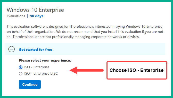
Figure 3.34 – Windows 10 Enterprise ISO file
You’ll need to select the 32-bit or 64-bit edition to start the download of the ISO file onto your computer. Once the Windows 10 Enterprise ISO file has been downloaded onto your computer, proceed to the next step.
- Open the VirtualBox Manager application and click on New to create a virtual machine within the hypervisor.
- Next, on the Create Virtual Machine window, click on Expert Mode to use the expert mode options for creating the virtual machine.
- The Create Virtual Machine user interface will switch to Expert Mode. Use the following parameters to create the virtual machine environment:
- Name: Windows 10 VM
- Type: Microsoft Windows
- Version: Windows 10 (64-bit)
- Memory size: 4,096 MB or greater
- Hard disk: Create a virtual hard disk now
The following screenshot shows the desired configurations:
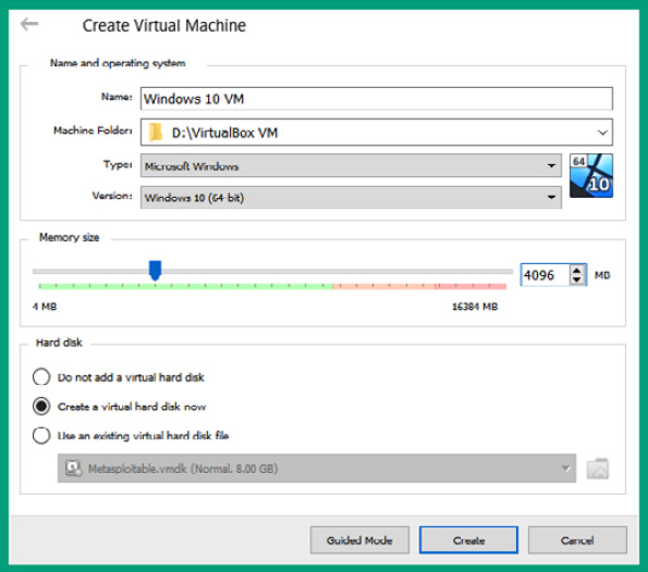
Figure 3.35 – Virtual machine configurations
Once you’ve set all the parameters, click on Create to proceed to the next step.
- Next, Create Virtual Hard Disk will appear. Ensure you apply the following configurations and click Create:
- File size: 50 GB
- Hard disk file type: Virtual Hard Disk (VHD)
- Storage on physical hard disk: Dynamically allocated
The following screenshot shows the desired configurations:
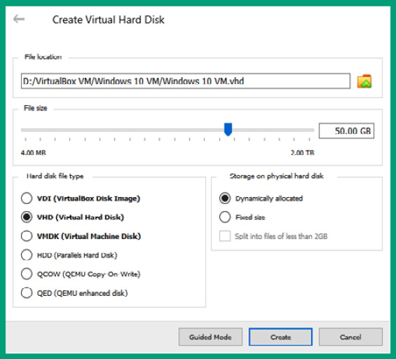
Figure 3.36 – Virtual hard disk configurations
- Next, your virtual machine environment will be created and you’ll return to the VirtualBox Manager main user interface. Select the Windows 10 VM virtual machine and click on Settings, as shown here:
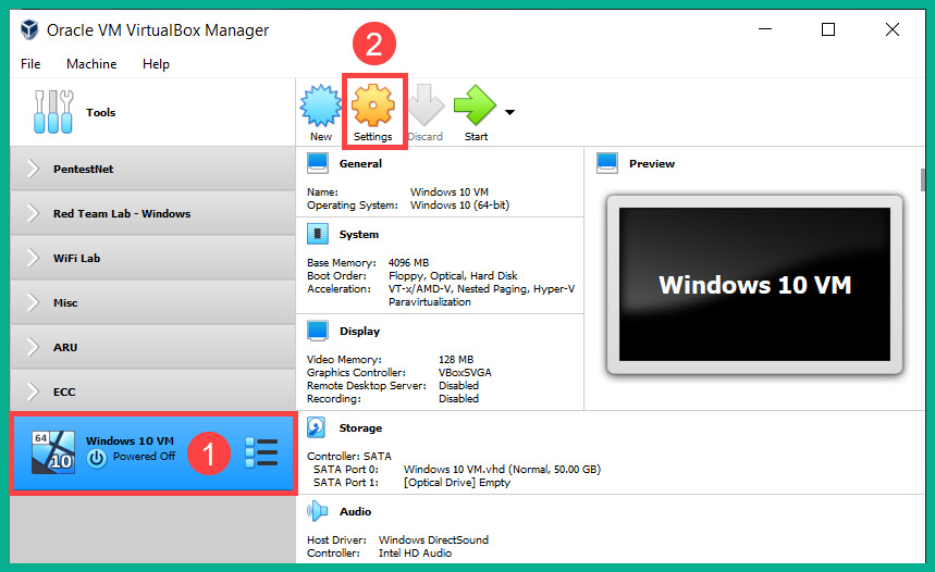
Figure 3.37 – Opening the Settings menu
- (Optional) To adjust the number of virtual processors allocated to the Windows 10 virtual machine, select System | Processor, as shown in the following screenshot:
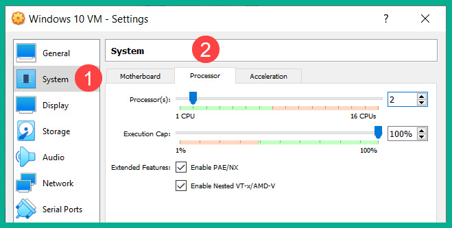
Figure 3.38 – Processor settings
- Next, to adjust the vNICs on the Windows 10 virtual machine, select Network | Adapter 1. To share the internet access from your host operating system to the guest operating system within the virtual machine, ensure Adapter 1 is enabled and set it to NAT, as shown here:
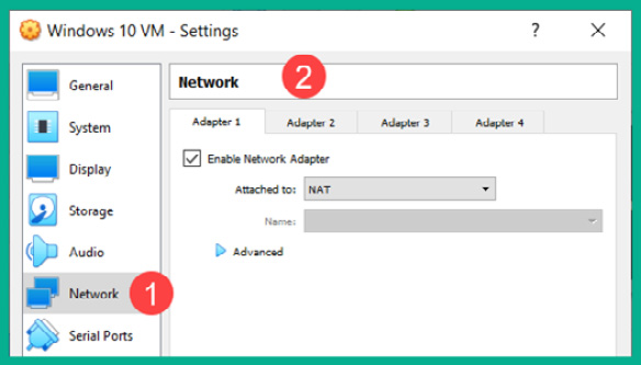
Figure 3.39 – Network adapter settings
- Next, to attach the Windows 10 Enterprise ISO file to the virtual optical drive, select Storage and click on the empty optical disk icon. Then, in the Attributes section, select the optical disk icon to open the drop-down area. Select Choose a disk File, as shown here:
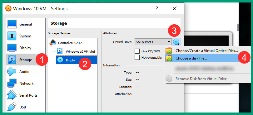
Figure 3.40 – Attaching a disk image
A new window will open. Simply navigate to the Windows 10 Enterprise ISO file location, and select and click Open to attach the file. Click OK to save and close the settings menu.
Part 2 – the installation process
- Next, on the VirtualBox Manager main user interface, select Windows 10 VM and click on Start to power on the virtual machine.
- The virtual machine will start and load the installation and boot files from the ISO file into the virtual memory on the virtual machine. On the Windows Setup window, click Next, as shown here:
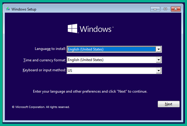
Figure 3.41 – The Windows Setup window
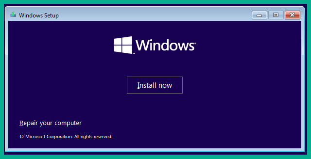
Figure 3.42 – The installation confirmation window
- Next, the Applicable notices and license terms window will appear. Simply accept the license terms and click Next.
- Next, select Custom: Install Windows only (advanced), as shown here:
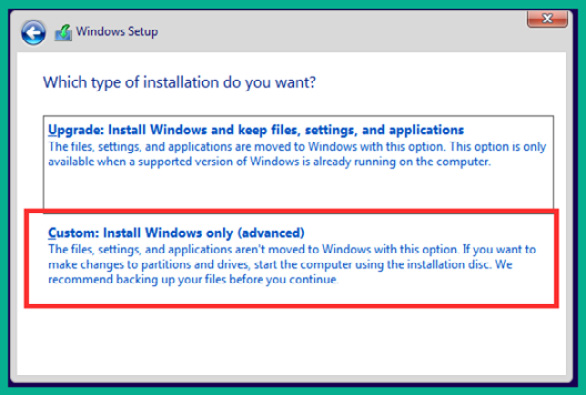
Figure 3.43 – Installation type
- Next, you’ll need to select the installation destination drive. Select the Drive 0 Unallocated Space option and select Next, as shown here:
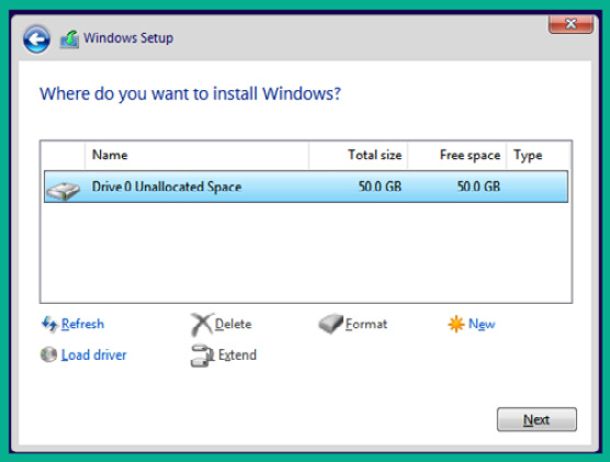
Figure 3.44 – Installation destination
The installation process will begin and will take a few minutes to complete. When the installation is completed, the operating system will automatically reboot on its own.
Part 3 – setting up Windows 10 Enterprise
- After the Windows 10 virtual machine reboots, select your region and keyboard layout and click Yes to proceed. The operating system will reboot again; this time, it can connect to the internet.
- In the Sign in with Microsoft window, select Domain join instead and click Next:
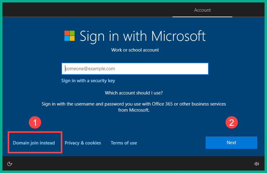
Figure 3.45 – Windows setup process
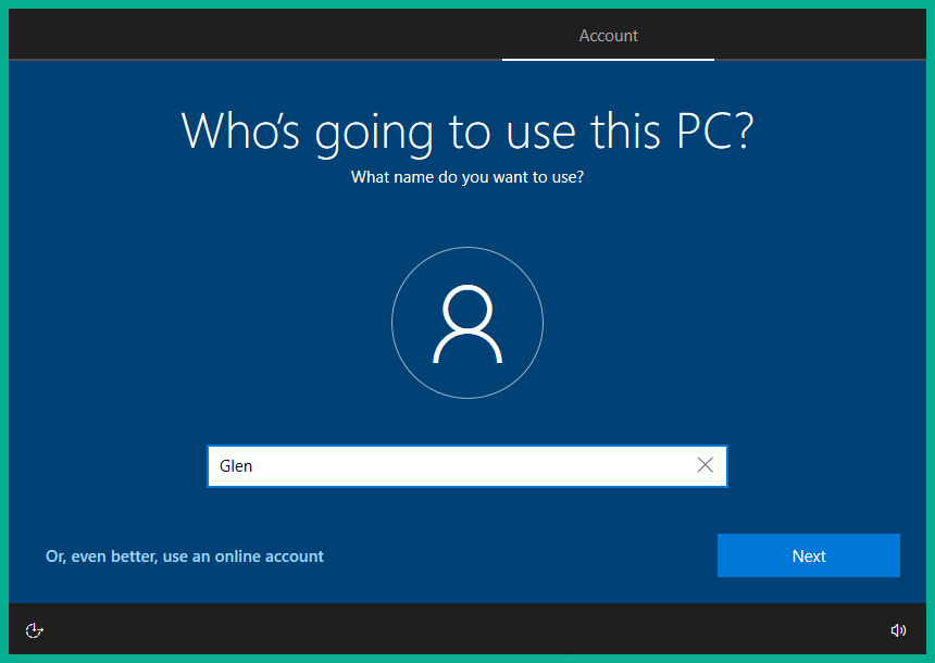
Figure 3.46 – Creating an identity
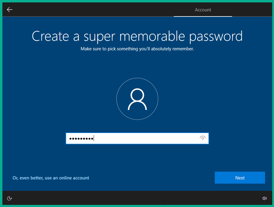
Figure 3.47 – Setting a password
- Next, you will need to confirm that the password has been configured correctly and set a few security questions.
- Next, you will be prompted to adjust the privacy and Cortana settings. You can disable all the collection of data and disable Cortana to proceed. The setup process will complete on its own and the operating system will automatically reboot and present the desktop, as shown here:
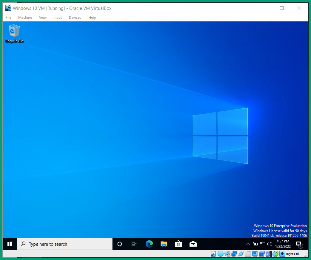
Figure 3.48 – Windows 10 user interface
Part 4 – installing guest additions
- On the Windows 10 VM menu bar, select Devices | Install Guest Additions CD image, as shown here:
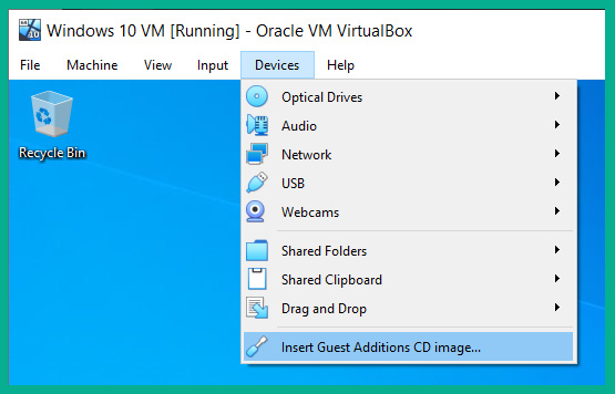
Figure 3.49 – Guest Additions
- Within the Windows 10 Enterprise virtual machine, open Windows Explorer and go to This PC, where you will see that the VirtualBox Guest Additions virtual disk is present. Double-click to open it:
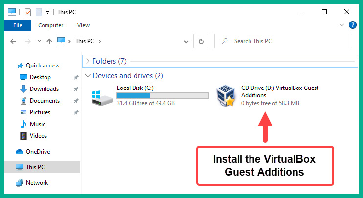
Figure 3.50 – Windows Explorer
- Double-click on the VboxWindowsAdditions file to start the installation. Ensure you use the default options during the installation process and install any driver application that may appear.
- Choose the Reboot now option when the VirtualBox Guest Additions installation is completed.
- After the installation is completed, you will need to select Input | Keyboard | Insert Ctrl + Alt + Del to provide the user input field to log in using the user account that was created during the setup process:
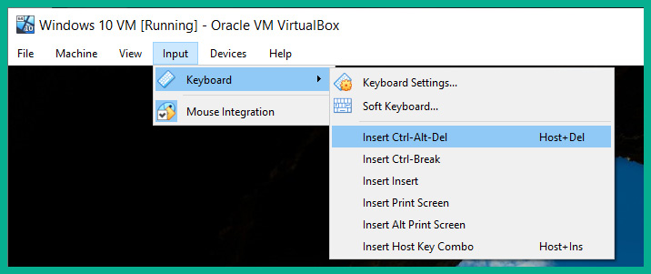
Figure 3.51 – Login window
- After you’ve logged into the operating system, click on View and toggle Auto-resize Guest Display to allow the guest operating system to automatically scale to your monitor’s resolution and size:
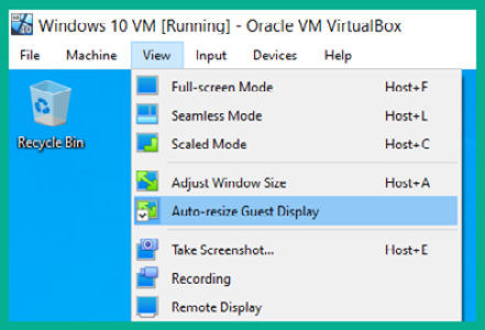
Figure 3.52 – Enabling Auto-resize Guest Display
Having completed this exercise, you have learned how to create a virtual machine and install Windows 10 Enterprise as a guest operating system on a hypervisor.
Summary
In this chapter, you learned about various Ethernet standards and their characteristics for copper and fiber cables, as well as their connection types. Furthermore, you learned about the importance of using cabling standards within organizations to maintain consistency and explored various virtualization technologies that are commonly used within the networking industry. Lastly, you gained skills in creating a virtual machine on a hypervisor.
I hope this chapter has been informative for you and is helpful in your journey toward learning networking and becoming a network professional. In the next chapter, Chapter 4, Understanding IPv4 and IPv6 Addressing, you will discover the various types and use cases of IPv4 and IPv6 addresses, and learn to perform subnetting.
Questions
The following is a short list of review questions to help reinforce your learning and help you identify areas that may require some improvement.
- How many pairs of wires are there within an STP cable?
A. 2
B. 3
C. 4
D. 8
- Which of the following cables is commonly used in telephone systems?
A. Cat 5
B. Cat 5e
C. Cat 6
D. Cat 3
- Which of the following connectors is used in new coaxial cables?
A. F-Type
B. SFP
C. RJ-48
D. BNC
- Which of the following fiber transceivers provides speeds of 40 Gbps?
A. SFP
B. QSFP+
C. GBIC
D. SFP+
- Which of the following is true about fiber cables?
A. Uses LEDs
B. Cheaper than copper cables
C. Less fragile than a coaxial cable
D. All of the above
- Which of the following is the standard for Ethernet?
A. IEEE 802.15
B. IEEE 802.11
C. IEEE 802.3
D. IEEE 802.16
- Which type of hypervisor can run directly on top of the hardware components of a server?
A. Type 2
B. Type 0
C. Type 1
D. All of the above
- Which of the following Ethernet standards supports 100 Mbps over a twisted pair cable?
A. 10BASE-SX
B. 100BASE-TX
C. 100BASE-T
D. 100BASE-LX
- Which of the following Ethernet standards support 100 Mbps over long-range Multimode Fiber?
A. 100BASE-FX
B. 100BASE-SX
C. 100BASE-LX
D. 100BASE-LR
- Which of the following Ethernet standards support 10 Gbps on short-range Single-Mode Fiber?
A. 10GBASED-FX
B. 10GBASED-LX
C. 10GBASED-SR
D. 10GBASED-LR
Further reading
To learn more about the topics that were covered in this chapter, check out the following links:
- Basic Home Network Hardware Components: https://stevessmarthomeguide.com/networking-components/
- Network Cabling: https://fcit.usf.edu/network/chap4/chap4.htm
- What is Virtualization?: https://www.vmware.com/solutions/virtualization.html