
4
Understanding IPv4 and IPv6 Addressing
Each device connected to a network needs a logical address to be able to communicate with other devices and share resources. Without logical addressing, a sender will not be able to specify the delivery address or location for a message, and a recipient of a message will not know the sender’s address if a response is needed. Within private networks within organizations and public networks on the internet, each device is assigned a logical address, which helps networking devices forward messages between a source and a destination.
In this chapter, you will understand the need for public and private IP address spaces and why it matters to networking professionals and organizations. You will gain a solid foundation in understanding the various types of IPv4 and IPv6 addresses, and why these address types are needed on networks. Lastly, you will explore IPv6 concepts and learn how to configure IP addresses on various devices.
In this chapter, we will cover the following topics:
- The need for IP addressing
- Exploring the structure of IPv4 and IPv6
- Types of IPv4 and IPv6 addresses
- Delving into IPv6 concepts
- Configuring IP addresses
Let’s dive in!
Technical requirements
To follow along with the exercises in this chapter, please ensure that you have met the following hardware and software requirements:
- Windows 10: https://www.microsoft.com/en-us/evalcenter/evaluate-windows-10-enterprise
- Ubuntu 20.04 Desktop: https://ubuntu.com/download/desktop
- Cisco IOS router
The need for IP addressing
An Internet Protocol (IP) address is a Layer 3 logical address that is assigned to all devices on a network to allow communication between nodes on different IP networks. Imagine sending a letter to a friend or relative using traditional postal services. After writing the letter, you’ll need to include the sender’s address if the recipient wants to reply to your letter. Additionally, as the author of the letter, you’ll need to include the destination mailing address to ensure the courier service has all the details needed to deliver the letter to the right address and person. What if you forgot to include the source/sender address on the letter? The recipient will not be able to send any replies to you. What if you haven’t included the destination mailing address? The courier service will not be able to deliver the letter to the appropriate person.
Based on this analogy, the letter (message) is the electrical signal being generated by the sender’s computer. Before the message is placed on the network, the sender’s IP address is inserted as the source address and the recipient’s IP address is included as the destination address. These addresses are required to ensure any networking devices along the way can forward the message to the intended recipient. Without proper addressing information (IP addressing) on the letter (message), the postal service (networking devices) will experience difficulties forwarding the letter correctly.
In the world of networking, the Internet Assigned Numbers Authority (IANA) is the governing body that is responsible for managing global IP version 4 (IPv4) and IP version 6 (IPv6) address assignments, Autonomous System Number (ASN) allocation to organizations that manage a large number of public networks, protocol assignment, and root Domain Name System (DNS) directories and services of the world.
On the internet, each device that is directly connected to the internet needs a unique IP address. If there are two or more devices with duplicate IP addresses that exist on the internet or within a private network, the networking devices that are responsible for forwarding packets will experience issues delivering a unique stream of packets from a sender to the correct destination host. To assist with distributing public IP addresses to Internet Service Providers (ISPs) around the world, IANA delegated the responsibility of IP distribution to five Regional Internet Registries (RIRs) around the world. Each RIR is responsible for distributing IPv4 and IPv6 address blocks to specific regions and geolocation.
The following are the five RIRs and their responsible geolocations:
- African Network Information Center (AFRINIC): Supports the continent of Africa
- Asia-Pacific Network Information Centre (APNIC): Supports regions of Asia and the Pacific
- American Registry for Internet Numbers (ARIN): Supports regions of Canada, the USA, and parts of the Caribbean
- Latin America and Caribbean Network Information Centre (LACNIC): Supports Latin America and parts of the Caribbean regions
- Réseaux IP Européens Network Coordination Centre (RIPE NCC): Supports Europe, the Middle East, and Central Asia
The following diagram provides a visual representation of how the public IP addresses are distributed to each RIR and the ISPs around the world:
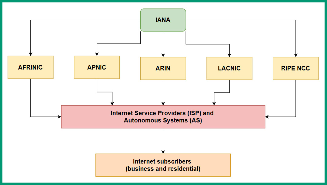
Figure 4.1 – IP network blocks delegation
As shown in the preceding diagram, each RIR is responsible for distributing IPv4 and IPv6 address blocks to ISPs and any Autonomous System (AS) within their responsible geolocation. An AS is simply any organization that is responsible for managing a large number of internet routing networks such as an ISP within a country or region. IANA assigns AS numbers to the various RIRs around the world. Then, the RIRs allocate these AS numbers to network operators such as ISPs. The ISPs use their AS numbers to share their network routing prefixes with other ISPs using the Border Gateway Protocol (BGP).
Important note
BGP is an Exterior Gateway Protocol (EGP) that allows network operators such as ISPs to exchange their routing information with each other, allowing users on the internet to reach networks beyond their local ISP.
The following diagram shows a network representation of many interconnected network operators:
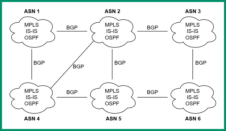
Figure 4.2 – Interconnected ISPs sharing network routes
As shown in the preceding diagram, each network operator or ISP is assigned a unique AS number that allows them to interconnect and share their network routes with other ISPs while using BGP to share their routes. Internally, network operators use various Interior Gateway Protocols (IGPs) such as Open Shortest Path First (OSPF), Intermediate System to Intermediate System (IS-IS), and Multiprotocol Label Switching (MPLS) to route traffic within their networks.
Tip
Many islands and continents are interconnected using submarine internet cables that are installed on the ocean’s floor around the world. The following URL provides a visual map of the underwater submarine cables and the organizations that manage them: https://www.submarinecablemap.com/.
In the early days, back in January 1983, the world began seeing the deployment of IPv4 addresses – 32-bit logical addresses that are written in a dotted-decimal notation. While 1983 may seem to be a long time ago, the internet is still in its early phases and continuously growing as more devices and organizations’ networks are connecting to it. As the internet began to grow quickly, IPv4 addresses for the internet were determined to one day be exhausted over time. As early as 1999, the world began to see a new generation of logical addresses being deployed, known as IPv6 addresses. These are 128-bit logical addresses that are written in hexadecimal notation.
IANA implemented the concept of creating two logical address spaces for IPv4 to help reduce the depletion of IPv4 addresses around the world. In the next section, you will learn about the importance of these two IPv4 address spaces and how they are used to reduce wastage while ensuring private networks can communicate on the internet.
Public versus private address spaces
IANA created two separate IPv4 address spaces to help reduce the depletion of IPv4 addresses around the world. These IPv4 address spaces are known as the public address space and the private address space. The public address space specified the IPv4 addresses that are routable on the internet and can be assigned to devices that are directly connected to the internet. The private address space specifies the classes and ranges of IPv4 addresses that are non-routable on the internet and can be assigned to devices on private networks only.
The following table shows the public classes of IPv4 addresses:
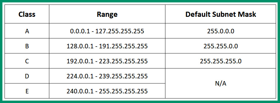
Figure 4.3 – IPv4 public address space
As shown in the preceding table, classes A, B and C can be assigned to devices that are directly connected to the internet. The Class D address range is used for multicast communication between applications and services that operate on devices within a network, and the Class E address range is reserved for experimental uses.
Important note
The subnet mask is used to determine the network and host portion of an IP address, and the total number of IP addresses and usable IP addresses within a network.
In the early days of the internet, the IPv4 address space didn’t have a proper structure as it does in today’s world. Originally, the IPv4 address spaces used classful addresses, which describe how each IPv4 address class contains a specific number of networks. Here, each network contains a specific number of usable/assignable IPv4 addresses to host devices.
To get a better idea, the following table shows the IPv4 classful addressing information:
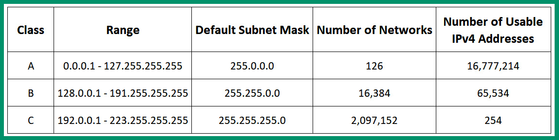
Figure 4.4 – Classful IPv4 addresses
As shown in the preceding table, the classes of IPv4 addresses are the same as the public address space. However, within the Class A range, there’s a total of 126 networks and each of those networks contains 16,777,214 usable IPv4 addresses that can be assigned to hosts on a network. The Class B range provides a total of 16,384 networks and each of those networks contains 65,534 usable IPv4 addresses that can be assigned to host devices on a network. Lastly, the Class C range contains a total of 2,097,152 networks and each of those networks contains 254 usable IPv4 addresses for hosts on a network.
One of the major issues with classful addressing is the wastage of unused IP addresses within an organization. Imagine that an organization with 2,000 devices requires a network block of addresses to assign to their company’s network. A Class B address block would be most suitable in this situation. However, since any Class B network provides 65,534 usable IPv4 addresses, there will be a huge wastage of 65,534 – 2000 = 63,534 unused addresses that cannot be allocated to another organization. Simply put, organizations that were assigned very large IPv4 network blocks with too many addresses led to wastage. Keep in mind that during the era of classful addressing, all devices on the internet and those within private networks of the organization were all using classful addressing (public IPv4 addresses) that was routable on the internet.
Furthermore, let’s say an organization has 400 devices and needs IPv4 addresses to assign to its network. The organization will need to lease a Class B address block that contains too many IPv4 addresses or multiple Class C address blocks to support the number of hosts. Therefore, classful addressing was not flexible enough to support organizations of various sizes.
Additionally, when the internet used classful addressing, the routers within service providers’ networks contained very large routing tables, which affected the performance of a router on forwarding a packet to its destination. The routing table within a router contains routes (paths) that indicate how to reach a destination network. Therefore, for every packet that enters a router, the destination IP address is observed and the router checks the routing table for a route that matches the destination IP address. The router checks the routing table from top to bottom each time it has to perform a route lookup, stops with a suitable route it found, and forwards the packet using the route information. Imagine if routers on the internet have a very huge routing table, containing all the classful networks of the internet. Here, each router will take some time to go through its routing table to find a destination path to forward a packet. This is another issue with classful addressing on the internet.
When working with classful addresses, everyone needed to use the default subnet mask with the corresponding address block that was assigned to their organization. Companies were not able to logically segment their networks into multiple IP subnetworks from a single network block, which was not flexible for businesses of different sizes. A simple example is a business with 90 host devices that would be assigned a Class C network block that contains 254 usable IPv4 addresses. Any unused IPv4 addresses were not reallocated to another organization.
The idea of using classful addressing on the internet was not flexible to support the growth of the internet and organizations and did not minimize the wastage of IPv4 addresses. One solution was to implement classless addresses, which removed the need to use a default subnet mask for a specific range of IPv4 addresses. In this case, a Class A IPv4 address does not need to use the default subnet mask of 255.0.0.0 in classless addressing. When using classless addressing, the rules of using the default subnet mask are not applied, allowing networking professionals to use custom subnet masks with any IPv4 address.
To help reduce the wastage of public IPv4 addresses, IANA created the private IPv4 address space, which allows organizations to use a specific set of IPv4 addresses on private networks. These private IPv4 addresses are non-routable on the internet, which means if a computer is assigned a private IPv4 address, it will not be able to communicate with devices on the internet and vice versa. Imagine if all devices within the private networks of organizations were configured with a unique public IPv4 address – the public address space would be exhausted a lot quicker than expected. Therefore, the private address space allows organizations to assign a unique private IPv4 address on devices within their private networks without worrying about depleting the available number of public IPv4 addresses on the internet.
The following table shows the private IPv4 address space:
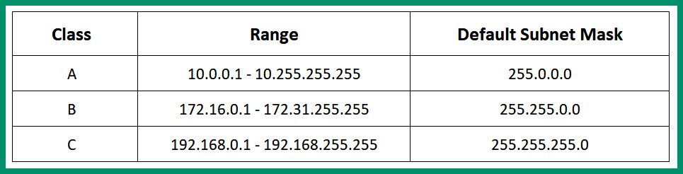
Figure 4.5 – Private IPv4 address space
As shown in the preceding table, the private IPv4 address spaces contain three classes of address ranges. Each class of address can be used within any organization’s private network. This means two or more organizations can be using the same private IPv4 address classes within their private networks without causing any conflict.
Important note
The private IPv4 address is defined by RFC 1918: https://www.rfc-editor.org/rfc/rfc1918.html.
Simply put, if a device such as a computer was configured with a private IPv4 address and was directly connected to the internet, communication will not occur between the computer and devices on a public network such as the internet. Internet Service Providers (ISPs) usually implement security mechanisms such as an Access Control List (ACL) to filter traffic originating from their customers’ networks that have source private IPv4 addresses, therefore separating the private and public address spaces from meeting each other. Before devices on a private IPv4 network can communicate with devices with public IPv4 addresses on the internet, the source private IPv4 address has to be translated into a public address.
Next, you will learn about a very common IP service that allows a private IPv4 network to communicate with a public network such as the internet.
Network Address Translation (NAT)
Network Address Translation (NAT) is an IP service that is commonly found on almost all private networks within organizations. NAT allows a private IPv4 source address to be translated into a public IPv4 address, allowing devices on a private network to communicate with devices on a public network. Without NAT, the private and public IPv4 address spaces will not be able to communicate and this would create a major issue. Imagine that organizations are implementing a private IPv4 addressing scheme on their private, internal networks and can’t communicate with any servers or devices on the internet. To help ensure devices on a private IPv4 network can communicate with the internet, a NAT-enabled router is implemented between the networks.
The following diagram shows an example of a NAT-enabled router between a private and public network:
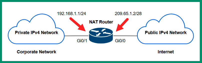
Figure 4.6 – NAT router
As shown in the preceding diagram, there’s a private IPv4 network on the left that indicates an organization’s private network while on the right there’s the internet, where all devices are assigned a public IPv4 address. To interconnect these two different networks, a router is implemented to route traffic between the different networks. Additionally, to ensure devices on the private network can communicate with devices on the internet, NAT is configured on the router to translate any source IPv4 address that originates from the private network to the public IPv4 address that’s configured on the router. Therefore, all outbound traffic from the corporate network to the internet will be assigned a new source IPv4 public address of 209.65.1.2. This allows devices on the internet to see the source traffic as originating from a device with a public IPv4 address of 209.65.1.2 and not from the private IPv4 network.
Usually, when a residential user subscribes to an internet service, the local ISP installs a modem on the customer’s premises. The modem is a multi-functional device that allows the customer’s private network to interconnect with the service provider’s public network. Furthermore, the modem is preconfigured by the service provider to perform NAT, allowing the private IPv4 addresses of devices on the customer’s network to be translated to the public IP address on the modem before the messages are sent out to the internet.
The following diagram is a visual representation of a NAT translation:
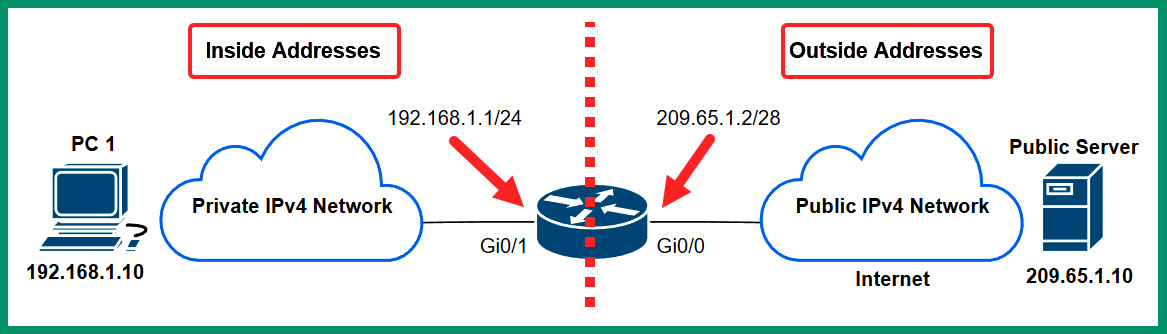
Figure 4.7 – NAT operations
As shown in the preceding diagram, all devices on the left are connected to the private IPv4 network, while all devices on the right are connected to the internet with a public IPv4 address. Additionally, the NAT-enabled router/modem identifies the addresses as inside and outside. The inside addresses are the private IPv4 addresses that are to be translated by the NAT-enabled router/modem. The outside addresses are those that are seen by all devices on the public address space – the internet. PC 1 is connected to a private network within an organization and it’s assigned a private IPv4 address of 192.168.1.10. This address is referred to as the Inside Local address. If PC 1 attempts to send a message to the Public Server on the internet, the packets from PC 1 will be restricted from entering the server provider’s network and the internet.
The following steps explain how NAT works:
- PC 1 creates a packet with the source IPv4 address of 192.168.1.10 (Inside Local) and a destination address of 209.65.10 (Outside Global), and forwards the message to the default gateway (router) at 192.168.1.1.
- The router inspects the source and destination IP addresses within the IP header of the packet to determine the destination and checks its routing table for a route (path).
- Before the router forwards the packet to the internet, it translates the source private IPv4 address from 192.168.1.10 to the public IPv4 address on the router as 209.65.1.2 (Inside Global), then sends the packet to the destination server.
- The Public Server will see the source IPv4 address of the packet as 209.65.1.2 (router) but not PC 1 because NAT allows the private network to be hidden behind the public IPv4 address of the router.
The following are various advantages of using NAT on a network:
- The primary benefit of using NAT is to help conserve the public IPv4 address space by allowing organizations to use private IPv4 addresses on their internal networks and be assigned a single public IPv4 address on their modem/router. NAT allows private IPv4 addresses to be translated to a public IPv4 address.
- Using NAT allows an entire organization’s private network to be hidden behind a single public IPv4 address. Within an organization, there may be hundreds and thousands of devices using private IPv4 addresses, and traffic from those devices can all be translated into a single public IPv4 address before they are sent out to the internet.
- Network professionals can maintain consistency in their private IPv4 addressing scheme within their companies. Since private IPv4 addresses are non-routable on the internet, organizations can use any private IPv4 address blocks on their private, internal networks. A NAT-configured router/modem handles all the translations of private IPv4 addresses to a public address.
While there are many benefits of using NAT on a network, there are some disadvantages that all network professionals need to know. The following are some disadvantages of NAT:
- Since the router or modem has to translate the private IPv4 address into a public one, network performance is affected. As traffic is sent to the router or modem to be translated before it is placed on the network, there is some delay as the router or modem has to perform the actual translation process.
- Since NAT modifies the IPv4 addresses on the packet, Virtual Private Network (VPN) solutions that use IP security (IPsec) to establish a secure logical tunnel over an unsecure network does not work well. When NAT changes the IPv4 addresses, it prevents the IPsec VPN tunnel from being successfully created.
- NAT modifies the IPv4 addresses within the packet, so end-to-end connectivity is lost between a sender and receiver. This makes it difficult for a receiver to determine the true source of a message, so the sender device can be hidden behind a public IP address on the internet.
Three types of NAT are commonly implemented within organizations by network professionals to allow devices on the private network to communicate with devices on the public network and vice versa. The following are the three common types of NAT:
- Static NAT
- Dynamic NAT
- Port address translation (PAT)
Static NAT allows network professionals to create a one-to-one mapping between an Inside Local address such as a private IPv4 address on an internal server to an Inside Global address such as the public IPv4 address on the router/modem internet-facing interface.
The following diagram shows an example of using Static NAT to access an internal web server:
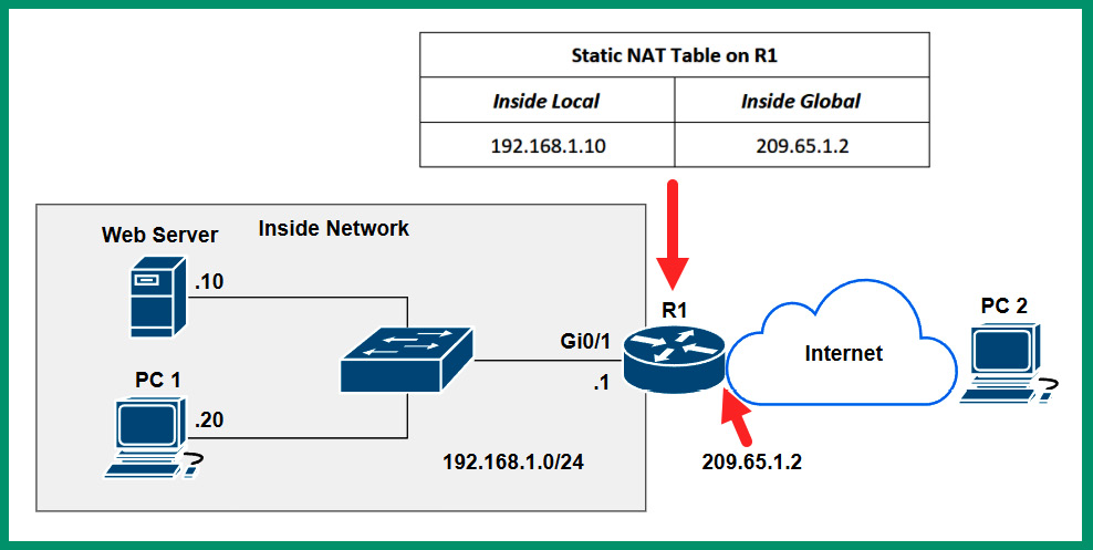
Figure 4.8 – Static NAT
As shown in the preceding diagram, there’s an internal web server on a private IPv4 network that is inaccessible by any device on the internet. Network professionals can use Static NAT to create a one-to-one mapping between the private IPv4 address of the server (192.168.1.10) and the public IPv4 address on the router (209.65.1.2). Therefore, whenever a device on the internet such as PC 2 connects to the public IPv4 address of 209.65.1.2, the router will forward all packets to 192.168.1.10, the internal web server. The user on the internet, PC 2, will not see the private IPv4 address on the internal network because it’s being hidden behind the public IPv4 address on the router.
Important note
When using Static NAT, the one-to-one mapping remains as-is on the router or modem until it’s modified by the network professional. Keep in mind that Static NAT mapping will forward all traffic types between a public IP address to a private IP address.
Whenever a company hosts an internal web server, they can either obtain a public IP address from their local ISP or assign a private IPv4 address and use static NAT to allow users from the internet to access the private internal server. Internet users would simply use the public IP address; when the organization’s NAT-enabled router receives inbound traffic from the internet, the router checks for any valid NAT mappings for a valid entry. Once an entry is found, the traffic is sent to the private internal host. The internet user would think the server has a public address and not realize a NAT translation is taking place in the background.
Dynamic NAT allows network professionals to create a many-to-many mapping between multiple private IPv4 addresses and public IPv4 addresses address. In dynamic NAT, a pool of public IPv4 addresses are assigned to the private IPv4 addresses on a first come, first served basis. If there are six public IPv4 addresses within the pool, and there are 50 devices on the internal network, only a maximum of six devices can use the available public IPv4 addresses at a time. If a seventh device wants to communicate over the internet while the pool is exhausted, the seventh device will need to wait until one of the public IP addresses is made available by the router.
The following diagram shows an example of a Dynamic NAT router:
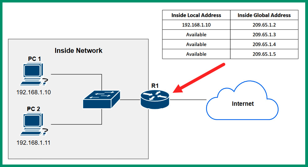
Figure 4.9 – Dynamic NAT
As shown in the preceding diagram, when PC 1 wants to communicate with a device on the internet, the router will check the NAT pool for an available public IPv4 address to translate the source private IPv4 address into a public address before forwarding the packet to the destination on the internet. While PC 1 is using the 209.65.0.1 address, if another internal device such as PC 2 wants to communicate with a server on the internet, the same process occurs on the NAT-enabled router and uses the next available public IPv4 address within the pool. However, if all addresses within the NAT pool are being used, additional devices on the internal network will need to wait until an address becomes available.
Port address translation (PAT), sometimes referred to as NAT overload, is one of the most common types of NAT that is found within many organizations and residential internet subscriber networks. PAT allows organizations and home users to perform a many-to-one translation. PAT allows multiple devices with private IPv4 addresses on the internal network to translate their source address to a single public IPv4 address using a NAT-enabled router or modem.
PAT is the most conservative type of NAT within the industry as it allows ISPs to assign a single public IPv4 address to each organization. The network professionals within companies can configure their routers to perform NAT overload, allowing multiple devices to translate their private addresses to the same public address for communication on the internet. Unlike Static and Dynamic NAT, NAT overload includes the source and destination service port numbers of each communication. Using the source and destination service port numbers allows the NAT-enabled router to uniquely identify and track each communication between the private (inside) and public (outside) networks.
The following diagram shows an example of NAT overload:
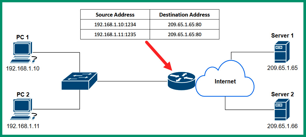
Figure 4.10 – Port address translation
As shown in the preceding diagram, when PC 1 wants to communicate with Server 1 on the internet, PC 1 creates a message to include the source and destination IPv4 addresses and service port numbers. When the message arrives at the NAT-enabled router or modem, the router records the source IPv4 address and service port number. Then, it translates the source private IPv4 address to the public IPv4 address while the source service port number remains unchanged. The NAT-enabled router keeps track of all translations, so any returning traffic from Server 1 will be forwarded to PC 1 only.
Having completed this section, you should now be able to describe the private and public IPv4 address spaces. You also discovered the various types of NAT and their use cases. In the next section, you will gain a deeper understanding of IPv4 and IPv6 address types.
Exploring the structure of IPv4 and IPv6
As an aspiring network professional, it’s important to understand the structure of both IPv4 and IPv6 addresses and how they differ from each other. In this section, you will learn how to convert IPv4 addresses from binary into decimal and vice versa, and explore various address types and their use cases on a network.
Fundamentals of IPv4
Working with computers and servers is quite fascinating for many people as the age of technology is ever-growing and continuously evolving in so many ways. When working with computers or even an IoT device such as a smartphone, there’s an operating system that controls the hardware components and allows us to leverage the computing power from the hardware to perform tasks and perform calculations. As a user, operating systems are very well polished to provide us with an amazing experience without having to understand the low-level programming language or worry about interpreting the electrical signals to and from your device.
When devices on a network send or receive a message, it’s in the form of electrical, light, or Radio Frequency (RF) signals. The messages that are sent back and forth between devices contain logical addressing, such as the mailing address to a destination host on the network. These electrical signals are commonly represented in 1s and 0s, where a 1 indicates a high voltage and a 0 indicates a low voltage on the wire. These 1s and 0s are important in the world of computing and networking, because data is represented on a computer as 1s and 0s, and IP addresses are written in dotted-binary notation and dotted-decimal notation to help the human mind understand them.
Within an IPv4 address, four octets are separated by a dot (.), and each octet is made up of 8 bits. Therefore, 4 octets x 8 bits per octet = 32 bits in length per IPv4 address. The following is an example of an IPv4 address in dotted-decimal and binary notation:
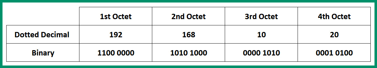
Figure 4.11 – IPv4 address format
As shown in the preceding diagram, each octet has a total of 8 bits and each octet is separated with a dot (.), so the IPv4 address is 192.168.10.20 = 11000000.10101000.00001010.00010100. As an aspiring network professional, it’s essential to learn how to convert IPv4 addresses between decimal and binary. This skill is needed to better understand how to perform subnetting and determine network ranges.
Converting binary into decimal
Let’s take a further look into the format of an IPv4 address with its binary format. Since an IPv4 address is 32 bits in length with four octets, the following is an example of an IPv4 address in binary notation:
11000000.10101000.00000001.10000001
When presented with a binary number, the challenge is to convert the dotted-binary number into a dotted-decimal number. To better understand how the conversion process works, first, you need to understand the purpose of a base system or radix in mathematics. The radix (base) is a unique number that is used in a positioning system. In binary, the base is 2, so the radix is the number 2. Using the positioning system, the first position value (starting from right to left) is 0 to 7.
The following table shows base 2 (radix) when used in the positioning system with 8 bits (one octet):
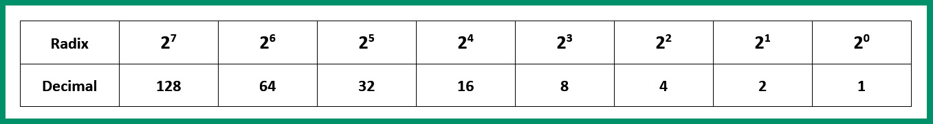
Figure 4.12 – Base 2 positioning system
Why did we use the range from 0 to 7 as our positioning values? We need to remember that the number zero (0) is the first of natural numbers and an integer on the numerical table, hence the reason we started with 20 as the first position. On the other hand, the last position is 27. This position represents the 8th position on the table. Since there are 8 bits in an octet, whenever you are converting an IPv4 address from binary into decimal notation, ensure you convert one octet at a time. This prevents any confusion or miscalculations during the conversion process.
Important note
In the world of mathematics, it’s important to remember the rule that A0 = 1.
To express the remaining positions with the radix of 2, the following is a further breakdown:
- 20 = 1
- 21 = 2 x 1 = 2
- 22 = 2 x 2 = 4
- 23 = 2 x 2 x 2 = 8
- 24 = 2 x 2 x 2 x 2 = 16
- 25 = 2 x 2 x 2 x 2 x 2 = 32
- 26 = 2 x 2 x 2 x 2 x 2 x 2 = 64
- 27 = 2 x 2 x 2 x 2 x 2 x 2 x 2 = 128
Additionally, the following list shows the full binary format to express each position value within an octet:
- 20 = 00000001 = 1
- 21 = 00000010 = 2
- 22 = 00000100 = 4
- 23 = 00001000 = 8
- 24 = 00010000 = 16
- 25 = 00100000 = 32
- 26 = 01000000 = 64
- 27 = 10000000 = 128
Now let’s apply the theory to converting the IPv4 address of 11000000.10101000.00000001.10000001 into a dotted-decimal notation. To perform this exercise, follow these steps:
- Let’s start with the first octet and place its values within the table, as shown here:
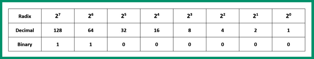
Figure 4.13 – Converting the first octet
As shown in the preceding table, each bit value is aligned with the positioning system. Let’s consider the columns with a binary number of 1. Here, the radix decimal value is ON. Therefore, within the table, both the 27 and 26 values are ON. This provides the following calculations:
27 + 26 = 128 + 64 = 192
- Using the same principle from the previous step, let’s assign the values of the second octet within the positioning system to determine its decimal value:
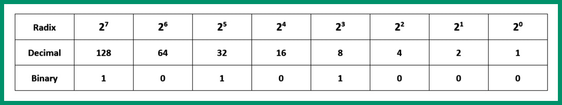
Figure 4.14 – Converting the second octet
As shown in the preceding table, the bits that are 1 (ON) are 27, 25, and 23. This provides the following decimal value:
27 + 25 + 23 = 128 + 32 + 8 = 168
- Next, let’s convert the third octet by placing its bit values within the positioning systems, as shown in the following table:
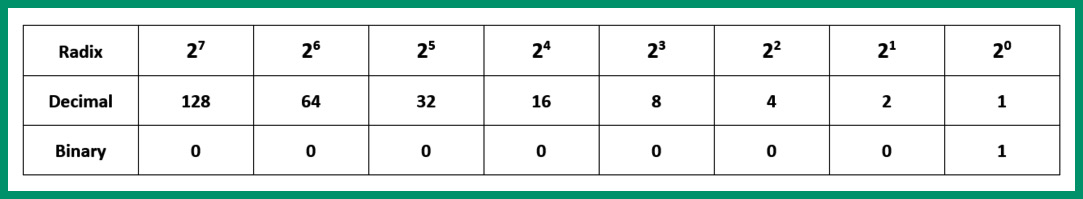
Figure 4.15 – Converting the third octet
As shown in the preceding table, the bit that’s ON is 20 = 1.
- Next, let’s convert the fourth octet by placing its bit values within the positioning system once more:
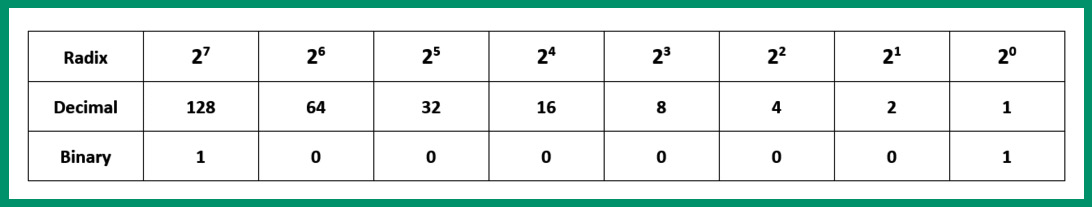
Figure 4.16 – Converting the fourth octet
As shown in the preceding table, the following bit values are ON:
27 + 20 = 128 + 1 = 129
- The final step is simply putting everything all together: 11000000.10101000.00000001.10000001 = 192.168.1.129.
Important note
If all bits are 1s within an octet, the total value will be 255. This means each octet ranges from 0 to 255. This implies a valid IPv4 address will never have an octet greater than 255.
Now that you have the skills to convert an IPv4 address from binary into decimal, let’s take a look at converting an IPv4 address from decimal into binary.
Converting decimal into binary
In this exercise, you will learn how to use an eight-step method to convert an IPv4 address, 172.19.43.67, from decimal into binary, one octet at a time. This eight-step method leverages the radix values in a slightly different approach while using basic subtraction to determine whether a bit is a 1 or 0.
The following are some guidelines to ensure the results are accurate:
- Always convert one octet at a time
- Always begin by subtracting the highest power of 2, which is 27 = 128, while working downwards to the lowest power of 2, which is 20 = 1
- If you can subtract the decimal number from the radix value, place a 1
- If you are unable to subtract the decimal number from the radix value, place a 0
- If you get a 0, then subtract the decimal number from the next lower radix value
Let’s start by converting the first octet, 172, from decimal into binary with the following steps:
- Is 172 – 128 (27) possible? Yes, with a remainder value of 44. Place a 1.
- Next, is 44 – 64 (26) possible? No, so carry the 44 forward to be subtracted from the next lower power of 2. Place a 0.
- Next, is 44 – 32 (25) possible? Yes, with a remainder value of 12. Place a 1.
- Next, is 12 - 16 (24) possible? No, so carry the 12 forward to be subtracted from the next lower power of 2. Place a 0.
- Next, is 12 – 8 (23) possible? Yes, with a remainder value of 4. Place a 1.
- Next, is 4 – 4 (22) possible? Yes, with a remainder value of 0. Place a 1.
- Next, is 0 – 2 (21) possible? No, so place a 0.
- Lastly, is 0 – 1 (20) possible? No, so place a 0.
Using the 1s and 0s from Steps 1 to 8, the binary value is 172 = 10101100.
The following diagram shows a visual representation of each step during the calculation process of converting 172 into a binary number:
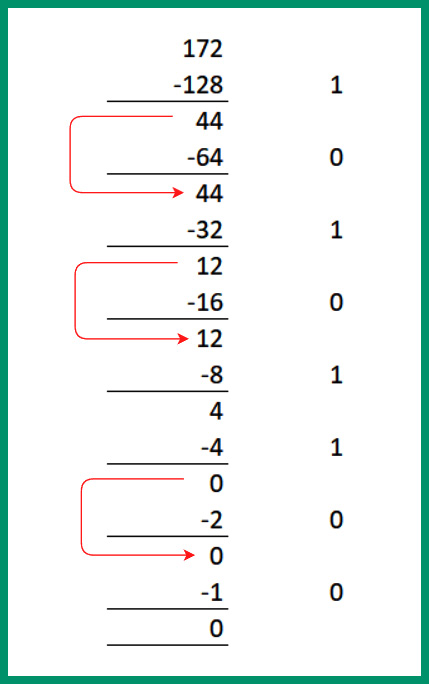
Figure 4.17 – Converting 172 into binary
Next, let’s convert the second octet, 19, from decimal into binary:
- Is 19 – 128 (27) possible? No, so carry the 19 forward to be subtracted from the next lower power of 2. Place a 0.
- Next, is 19 – 64 (26) possible? No, so carry the 19 forward to be subtracted from the next lower power of 2. Place a 0.
- Next, is 19 – 32 (25) possible? No, so carry the 19 forward to be subtracted from the next lower power of 2. Place a 0.
- Next, is 19 - 16 (24) possible? Yes, with a remainder value of 3. Place a 1.
- Next, is 3 – 8 (23) possible? No, so carry the 3 forward to be subtracted from the next lower power of 2. Place a 0.
- Next, is 3 – 4 (22) possible? No, so carry the 3 forward to be subtracted from the next lower power of 2. Place a 0.
- Next, is 3 – 2 (21) possible? Yes, with a remainder value of 1. Place a 1.
- Lastly, is 1 – 1 (20) possible? Yes, with a remainder value of 0. Place a 1.
Using the 1s and 0s from Steps 1 to 8, the binary value is 19 = 00010011.
The following diagram shows a visual representation of each step during the calculation process of converting 19 into a binary number:
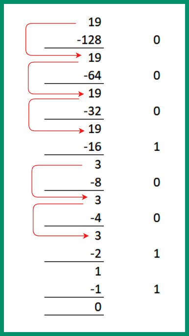
Figure 4.18 – Converting 19 into binary
Next, let’s convert the third octet, 43, from decimal to binary:
- Is 43 – 128 (27) possible? No, so carry the 43 forward to be subtracted from the next lower power of 2. Place a 0.
- Next, is 43 – 64 (26) possible? No, so carry the 43 forward to be subtracted from the next lower power of 2. Place a 0.
- Next, is 43 – 32 (25) possible? Yes, with a remainder value of 11. Place a 1.
- Next, is 11 - 16 (24) possible? No, so carry the 11 forward to be subtracted from the next lower power of 2. Place a 0.
- Next, is 11 – 8 (23) possible? Yes, with a remainder value of 3. Place a 1.
- Next, is 3 – 4 (22) possible? No, so carry the 3 forward to be subtracted from the next lower power of 2. Place a 0.
- Next, is 3 – 2 (21) possible? Yes, with a remainder value of 1. Place a 1.
- Lastly, is 1 – 1 (20) possible? Yes, with a remainder value of 0. Place a 1.
Using the 1s and 0s from Steps 1 to 8, the binary value is 43 = 00101011.
The following diagram shows a visual representation of each step during the calculation process of converting 43 into a binary number:
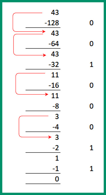
Figure 4.19 – Converting 43 into binary
Next, let’s convert the third octet, 67, from decimal into binary:
- Is 67 – 128 (27) possible? No, so carry the 67 forward to be subtracted from the next lower power of 2. Place a 0.
- Next, is 67 – 64 (26) possible? Yes, with a remainder value of 3. Place a 1.
- Next, is 3 – 32 (25) possible? No, so carry the 3 forward to be subtracted from the next lower power of 2. Place a 0.
- Next, is 3 - 16 (24) possible? No, so carry the 3 forward to be subtracted from the next lower power of 2. Place a 0.
- Next, is 3 – 8 (23) possible? No, so carry the 3 forward to be subtracted from the next lower power of 2. Place a 0.
- Next, is 3 – 4 (22) possible? No, so carry the 3 forward to be subtracted from the next lower power of 2. Place a 0.
- Next, is 3 – 2 (21) possible? Yes, with a remainder value of 1. Place a 1.
- Lastly, is 1 – 1 (20) possible? Yes, with a remainder value of 0. Place a 1.
Using the 1s and 0s from Steps 1 to 8, the binary value is 67 = 01000011.
The following diagram shows a visual representation of each step during the calculation process of converting 67 into a binary number:
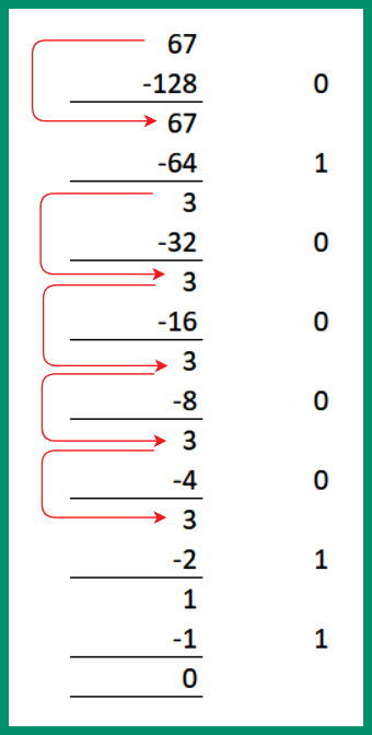
Figure 4.20 – Converting 67 into binary
Lastly, let’s put everything all together and view the binary notation of 172.19.43.67:
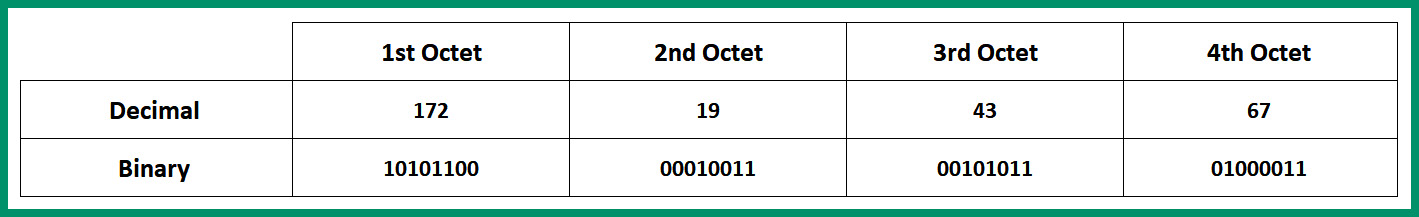
Figure 4.21 – Binary and decimal notation
As shown in the preceding table, the IPv4 address is 172.19.43.67 = 10101100.00010011.00101011.01000011.
Understanding how to convert between binary and decimal is an essential skill within networking as you will need it to understand how to break down an IPv4 network block into smaller subnetworks.
In the next section, you will explore IPv6 concepts and discover the differences between IPv4 and IPv6 addresses.
Fundamentals of IPv6
Like IPv4, this new address has a format of its own. As you may recall, an IPv4 address consists of 32 bits in length and it’s written in dotted-decimal notation for easier reading to the human mind. An IPv6 address consists of 128 bits in length and is written in hexadecimal notation. Hexadecimal contains both numbers and letters in the following range:
0 1 2 3 4 5 6 7 8 9 A B C D E F
This 128-bit address allows IPv6 to scale to 2128 IPv6 addresses, which allows 3.4 x 1038 IPv6 addresses that can be uniquely assigned to devices. Each IPv6 address is made up of 128 bits that are grouped into eight (8) hextets. Each hextet contains 16 bits, so 8 hextets x 16 bits per hextet = 128 bits in length per IPv6 address.
The following is an example of an IPv6 address:
2001:0DB8:0000:1111:0000:0000:0000:0200
Notice each hextet contains hexadecimal values between 0 and F and each hextet is separated by a colon (:). In hexadecimal, the least value is 0 and the highest value is F, so each hextet ranges from 0000 to FFFF.
Important note
When writing or entering the values of an IPv6 address on a device, the letters are not case-sensitive, which means both lowercase and uppercase are accepted on both ends, as well as on networking devices.
Let’s break down the following IPv6 address into a more simplified version:
2001:0DB8:0000:1111:0000:0000:0000:0200
First, all leading 0s in a hextet can be removed. When there are two or more hextets that are all zeros, a double colon (::) is used to replace the consecutive zeros within the IPv6 address. The following is a simplified version of the original IPv6 address:
2001:DB8:0:1111:0:0:0:200
Then, replace consecutive zero-only hextets with a double colon (::). The following is a further simplified version:
2001:DB8:0:1111::200
Important note
The double colon (::) can be used once in an IPv6 address.
Furthermore, when configuring an IPv6 address on a device such as a computer, server, or even a router, the host operating system of the device will accept both the full length of the address and the shortened versions. However, as an aspiring network professional, it’s important to understand how to create the most simplified version of an IPv6 address.
As with all IPv4 addresses, there’s usually a subnet mask to accompany it. The same also applies to IPv6. The default subnet mask or prefix length of an IPv6 address is /64. This means the first 64 bits of the IPv6 address represent the network portion of the address and the second portion represents the interface ID.
The following diagram shows the parts of an IPv6 address:
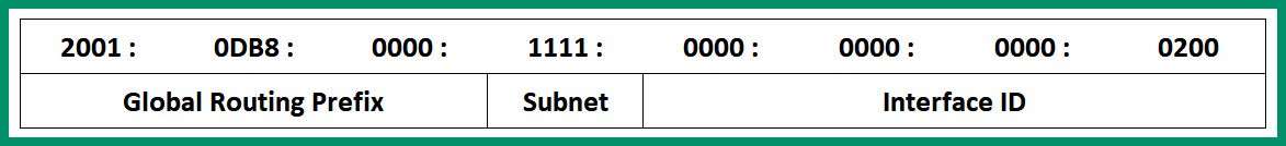
Figure 4.22 – IPv6 address structure
As shown in the preceding snippet, the first three hextets represent the Global Routing Prefix portion, which contains the first 48 bits of the address. This portion of the IPv6 address is assigned by the service provider such as the ISP. The fourth hextet (16 bits) represents the Subnet ID, which is used by the ISP to create subnetworks of the network block. The last 64 bits represent the Interface ID portion. Combining the Global Routing Prefix, Subnet ID, and Interface ID, a client is assigned a unique 128-bit IPv6 address on its network interface card.
Having completed this section, you have learned the fundamentals of both IPv4 and IPv6 addressing structures. In the next section, you will discover several addresses and their use cases on a network.
Types of IPv4 and IPv6 addresses
There are various types of IPv4 and IPv6 addresses and it’s important to understand them as an aspiring network professional. In this section, you will gain a solid understanding of the key characteristics of each address type and discover their role in networks.
Automatic Private IP Addressing (APIPA)
When a client device such as a computer or even a smartphone is connected to a wired or wireless network, the device is automatically assigned an IPv4 or IPv6 address from a Dynamic Host Configuration Protocol (DHCP) server. In large organizations, companies usually implement one or more dedicated DHCP servers on the network to ensure redundancy and proper distribution of IP addresses to nodes on the network. However, within smaller environments such as Small Office Home Offices (SOHOs), you will likely not see a dedicated DHCP server. Rather, the modem or router you’ve been provided by the ISP provides the DHCP services for clients on the LAN.
What if a computer connects to a network and does not receive an IP address? What happens? There are many reasons a client device may not receive an IP address from the network, as follows:
- The client is unable to communicate with the DHCP server on the network
- The client is configured to use a static IP address that does not change
- The DHCP server is not present or offline on the network
By default, many client devices are configured to automatically communicate with a DHCP server and receive an IP address from it. However, if a client is unable to reach the DHCP server on the network, the client will automatically assign itself a special unique IPv4 address ranging from 169.254.0.1 to 169.254.255.254 with a default subnet mask of 255.255.0.0. This is a feature known as Automatic Private IP Addressing (APIPA), which is built into many operating systems such as Microsoft Windows.
Important note
On an IPv4 network, the APIPA address is sometimes referred to as an IPv4 Link-Local address. However, APIPA is a Microsoft-specific term for “Link-Local,” which is preferred for Linux-based operating systems.
The following screenshot shows a Windows 10 client using an APIPA address on the network:
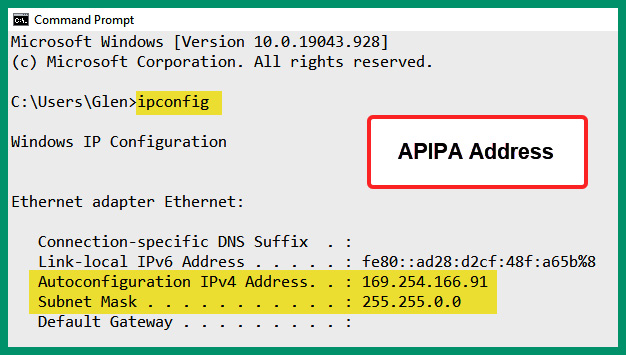
Figure 4.23 – APIPA address on a client
As shown in the preceding screenshot, the ipconfig command allows network professionals to view the local Network Interface Card (NIC) or network adapters on a Windows device and verify the IP addressing details on each network adapter. Furthermore, notice that the network adapter is using an IPv4 address that belongs to the APIPA range. Linux-based operating systems will use commands such as ifconfig, iwconfig, or ip instead of ipconfig.
Extended unique identifier (EUI-64)
On an IPv6 network, network professionals usually implement DHCPv6 servers to provide IPv6 addresses to clients. The DHCPv6 server keeps a record of each client that receives an IPv6 address and the lease time. However, on some IPv6 networks, network professionals implement a stateless IPv6 technology known as Stateless Address Autoconfiguration (SLAAC) that helps clients obtain global unicast IPv6 addresses on the network. One of the main differences between SLAAC and DHCPv6 is that SLAAC does not keep a record of each client’s IPv6 address assignment or details.
When using SLAAC on an IPv6 network, SLAAC provides the network portion of the IPv6 address to the client – that is, the first 64 bits of the IPv6 address. The client uses a process known as Extended Unique Identifier 64 (EUI-64) to convert its 48-bit Media Access Control (MAC) address into a 64-bit address, which will become the Interface ID portion of the IPv6 address. This allows the client to combine the 64-bit network prefix and the newly created EUI-64 address to create the 128-bit IPv6 address for the network adapter.
To get a better understanding of the EUI-64 process, let’s imagine a computer is connected to an IPv6 network and is seeking a DHCPv6 server. However, SLAAC is enabled on the network and provides the client with 2001:DB8:0:1111::/64, the network portion of the IPv6 address for its network adapter. The 48-bit MAC address is used on the computer’s network adapter and the EUI-64 process is used to create the 64-bit interface ID portion of a 128-bit IPv6 address.
The following steps describe the EUI-64 process of converting a 48-bit MAC address of a network adapter to create a 64-bit address that will be used as the interface ID portion to create a unique IPv6 address:
- First, split the 48-bit MAC address into half, separating the Organizational Unique Identifier (OUI) and the device portions, as shown in the following diagram:
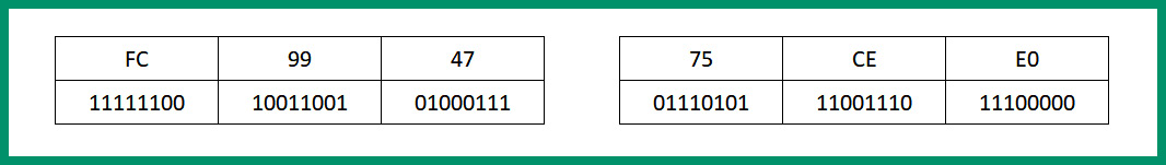
Figure 4.24 – EUI-64 process step 1
- Next, insert the hexadecimal value, FFFE, in the middle of the 48-bit MAC address, as shown in the following diagram:
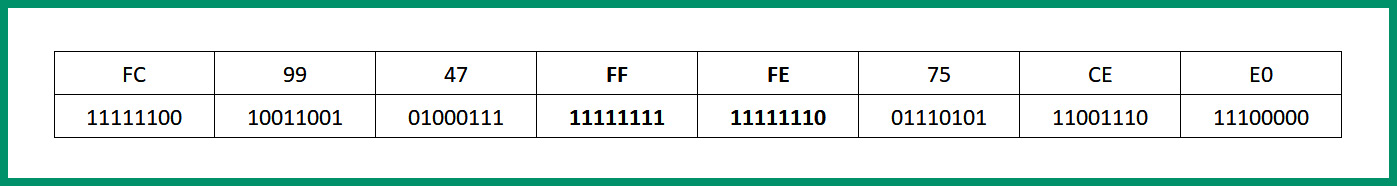
Figure 4.25 – EUI-64 process step 2
Important note
FFFE is a value reserved by IEEE and can only appear in a EUI-64 generated from a EUI-48 MAC address.
- Next, flip the seventh bit within the first byte so that a 0 will become a 1 or a 1 will become a 0. This bit indicates if the NIC is administered locally (0) or is globally unique (1), as shown in the following diagram:

Figure 4.26 – EUI-64 process step 3
- Next, convert the binary into hexadecimal to view the EUI-64 portion of the address, as shown in the following diagram:

Figure 4.27 – EUI-64 process step 4
- Lastly, putting it all together, the EUI-64 bit IPv6 address that will be assigned to the device’s network adapter is 2001:DB8:0:1111:FE99:47FF:FE75:CEE0.
Tip
To easily identify a EUI-64 address, the hexadecimal value of FFFE is always in the middle of the Interface ID portion of the IPv6 address.
The following screenshot shows a Cisco router with a EUI-64 IPv6 address on its interface:
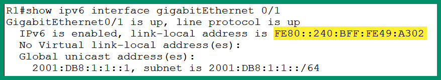
Figure 4.28 – EUI-64 address on a router
As shown in the preceding screenshot, the IPv6 address can easily be identified as the result of the EUI-64 process since FFFE is within the middle section of the Interface ID portion of the address.
Unicast
Unicast addresses can be IPv4 and IPv6 addresses that are uniquely assigned to the network adapter of a device. Using a unicast address allows one-to-one communication between a sender and receiver device over a network.
The following diagram shows an example of a unicast network transmission between two devices:
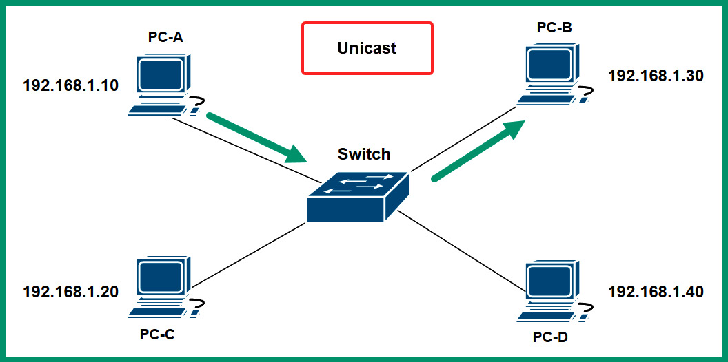
Figure 4.29 – Unicast communication
As shown in the preceding diagram, each device is assigned a unique IPv4 address on the network. Additionally, the IP address that’s configured on each device is a unique unicast address, which allows any device to communicate with another device.
The following screenshot shows an interface on a Cisco IOS router that’s been configured with a unicast address:
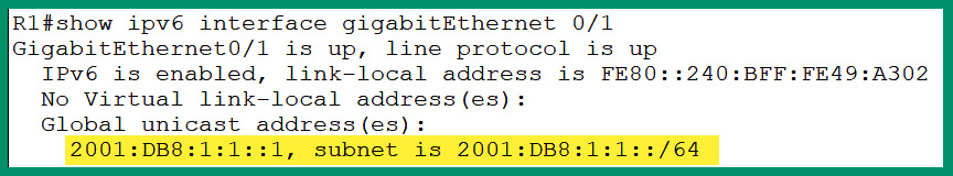
Figure 4.30 – IPv6 unicast address
As shown in the preceding screenshot, the Global Unicast Address (GUA) is configured on the GigabitEthernet 0/1 interface on the router. This IPv6 address is similar to a public IPv4 address that is routable on the internet. The GUA IPv6 addresses are globally unique on the internet as they are routable on the internet. At the time of writing, GUA IPv6 addresses use the 2000::/3 network block of addresses.
Multicast
Multicast addresses exist within both the IPv4 and IPv6 address spaces. Multicast allows one-to-many communication between devices on a network. Enterprise-grade routers within a large organization are usually configured with a dynamic routing protocol, which allows each router to automatically learn new networks and maintain an up-to-date routing table by exchanging routing information between themselves. These routers send and receive messages to a multicast address group, which is only used by devices running the same dynamic routing protocol.
The following diagram shows an example of multicast transmission over a network:
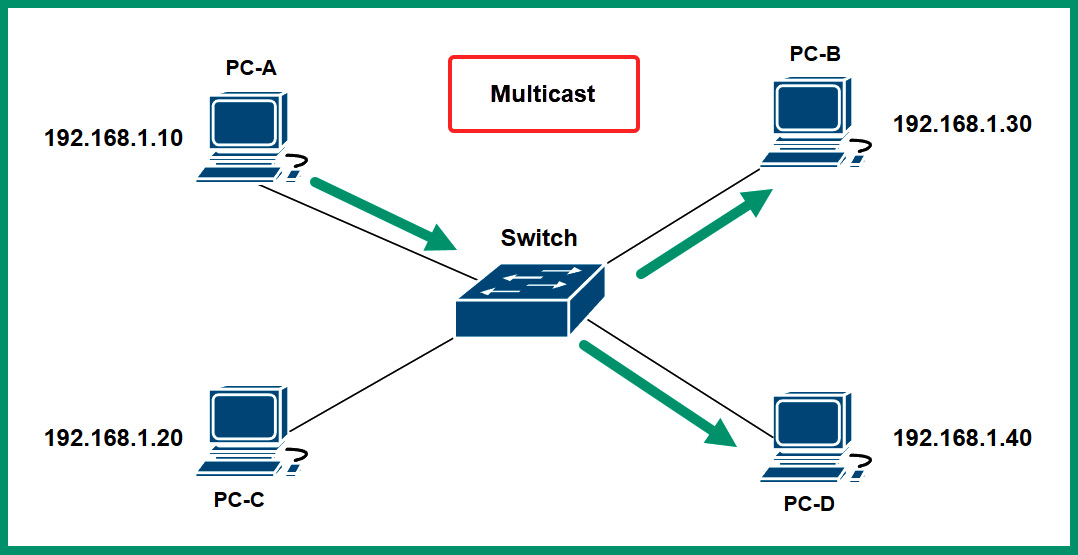
Figure 4.31 – Multicast communication
As shown in the preceding diagram, PC-A uses multicast to send messages to all devices that belong to the same multicast address group. Multicast IPv6 addresses have a network prefix of FF00::/8. The following is a list of IPv6 multicast addresses and their designated groups:
- FF02::1/12: All IPv6-enabled nodes on a network
- FF02::2/12: All IPv6-enabled routers on a network
- FF02::5/12: All routers that are running the Open Shortest Path First (OSPF) dynamic routing protocol
- FF02::A/12: All routers that are running the Enhanced Interior Gateway Routing Protocol (EIGRP) dynamic routing protocol
Next, you will learn about broadcast network transmission.
Broadcast
Broadcast allows one-to-all communication over an IPv4 network. Unlike IPv4 networks, IPv6 does not use broadcast addresses. Simply put, a computer that’s connected to a network can send a single message to the network’s broadcast address, which allows all devices within the same IP network to receive the message from the sender. Within a network that uses a Network ID of 192.168.1.0 and has a subnet mask of 255.255.255.0, the broadcast IP address will be 192.168.1.255.
The following diagram shows an example of broadcast transmission over a network:
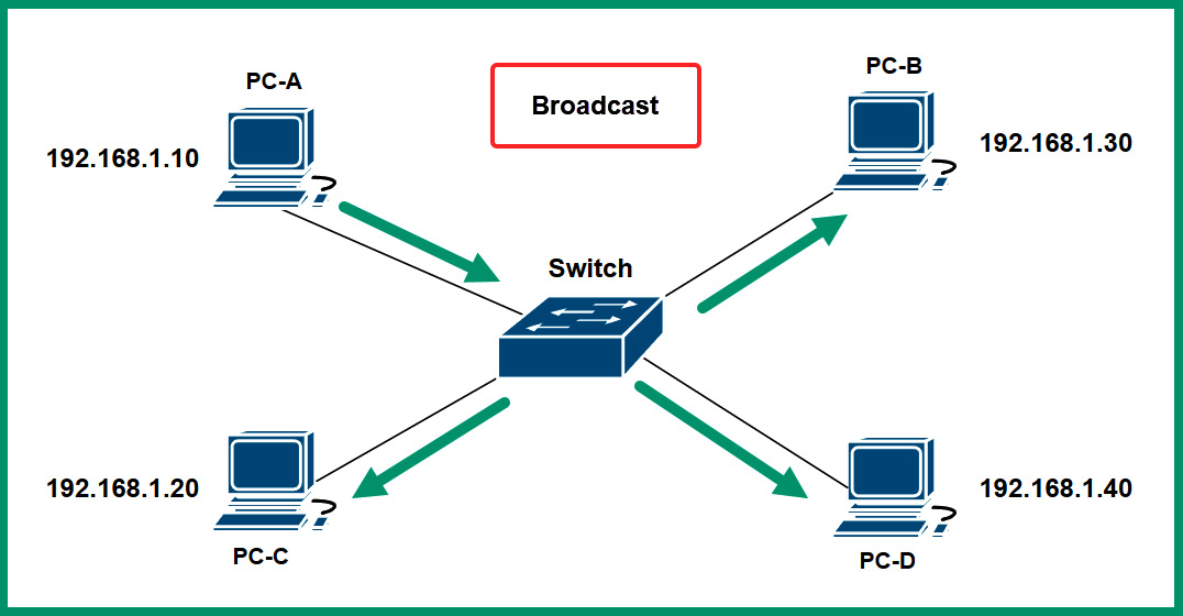
Figure 4.32 – Broadcast communication
As shown in the preceding diagram, PC-A sends a message to 192.168.1.255 and the message is delivered to all devices within the same IP network range. Keep in mind that having too many broadcast messages can affect the overall performance of the network, causing packet loss and high latency (slow response time) between devices.
Anycast
Anycast addresses exist on IPv6 networks and are used for one-to-nearest communication between devices over a network. Anycast allows the same unicast IPv6 address to be shared between multiple devices, such as servers on the internet. When a client such as a computer sends a message to an anycast IPv6 address, the message is delivered to the geographically nearest server that’s configured with the anycast address.
Link-local
On an IPv6 network, each device is assigned two IPv6 addresses on its network adapter. One of the addresses is the IPv6 unicast address, which is used by the device when communicating with other hosts outside its local network. If the computer on an internal network within an organization wants to communicate with a server on the internet, the IPv6 unicast address will be used for this type of communication.
Additionally, an IPv6 Link-Local address is assigned to the same network adapter with the IPv6 unicast address. The IPv6 Link-Local address is used when devices are communicating with each other on the same IPv6 local area network. This address is unique in the same IPv6 network, which means another IPv6 network can be using the same range of IPv6 Link-Local addresses. IPv6 Link-Local addresses belong to the FE80::/10 network block. This address is similar to the IPv4 APIPA addresses.
The following screenshot shows the interfaces on a Cisco router assigned IPv6 Link-Local addresses:
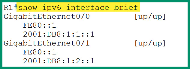
Figure 4.33 – Link-local addresses on a router
As shown in the preceding screenshot, the interfaces on the Cisco router are assigned both IPv6 unicast and link-local addresses. The IPv6 link-local addresses can easily be identified as they begin with FE80 as the first hextet within the IPv6 address.
Loopback
On a device, whether it’s a computer or even a networking device, there’s an operating system that controls the hardware-based components and leverages the computing power to perform tasks and operations. On a system, there are running services that allow the operating system to perform tasks in the background and applications to provide additional functionality. However, the host operating system sometimes needs to communicate with these running services, the application, and itself. The loopback address allows a host device to send network traffic to itself, which allows network professionals to determine whether the Transmission Control Protocol/Internet Protocol (TCP/IP) network model is working properly on the local device.
The IPv4 loopback address ranges from 127.0.0.1 to 127.255.255.254 and has a default subnet mask of 255.0.0.0 (/8). However, it’s quite common for network professionals to identify 127.0.0.1 as the loopback address as it’s the first IPv4 address within the range, and it’s mostly used when testing the loopback connectivity on a device.
The following screenshot shows how to test the loopback on a Windows operating system using the IPv4 loopback address:
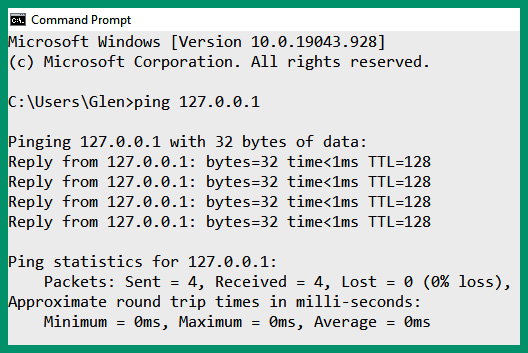
Figure 4.34 – IPv4 loopback address
As shown in the preceding screenshot, the ping tool was used to send four Internet Control Message Protocol (ICMP) Echo Request messages to the localhost using the IPv4 loopback address and the host responded to each message sent. This is an indication that TCP/IP is working fine for IPv4 connectivity.
In the IPv6 space, the loopback address is ::1/128, which allows network professionals to perform the same loopback testing on the TCP/IP network model on the local device. The following screenshot shows how to test the loopback on a Windows operating system using the IPv6 loopback address:
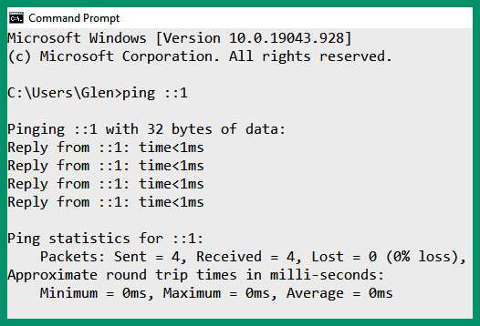
Figure 4.35– IPv6 loopback address
As shown in the preceding screenshot, the ping tool was used to send four ICMP ECHO Request messages to the local host and four responses were returned. The loopback addresses exist on all devices that support TCP/IP, such as smartphones and even IoT devices.
Unique local address
A unique Local address exists within the IPv6 addressing space and ranges from FC00::/7 to FDFF::/7. These unique local addresses have similarities to private IPv4 addresses on a network; they are unique to a private network within an organization and are non-routable on the internet. These unique local addresses are used for local addressing only and can be assigned to devices that do not need access to another network.
Default gateway
All devices that are connected to the same IP network can easily exchange messages and share resources. Each end device has a local routing table that contains the various network routes that are used by the local device to determine how to forward messages based on the destination IP address. The routing table of end devices is limited to the local area network and does not contain routes to public networks on the internet.
Therefore, if a device such as a computer attempts to forward a message to a host that does not exist within the same IP subnet as the sender, the computer will check its local routing table for a suitable route (path) to forward the packet. If a suitable route is not found, the sender will not be able to forward the message to the intended destination. Each device on a network requires a default gateway that allows them to forward messages when its local routing table does not contain a valid route for the destination of the message.
The following screenshot shows the default gateway address of a Windows 10 client on a private:
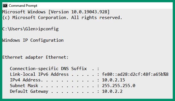
Figure 4.36 – Default gateway
As shown in the preceding screenshot, the client has an IPv4 address of 10.0.2.15/24 with a default gateway of 10.0.2.2. Any time the client has to forward a message, it checks its local routing table for a valid route. If a valid route is not found for the destination IP address of the message, the client forwards the message to the default gateway. The default gateway is the default or primary doorway to communicate outside of a local network.
The following screenshot shows the routing table of a Windows 10 computer:
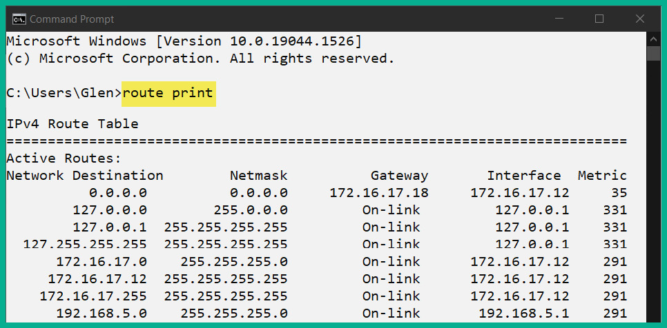
Figure 4.37 – Routing table of a Windows device
As shown in the preceding screenshot, the route print command is used to display the routing table of a Windows system. Looking closely, you’ll see a list of destination networks, their network (subnet) masks, and their associated default gateways. A destination network of 0.0.0.0 with a subnet mask of 0.0.0.0 is a default route that points to the internet via a default gateway that has the 172.16.17.18 address.
The following screenshot shows the routing table of a Linux-based device running the Ubuntu Desktop operating system:
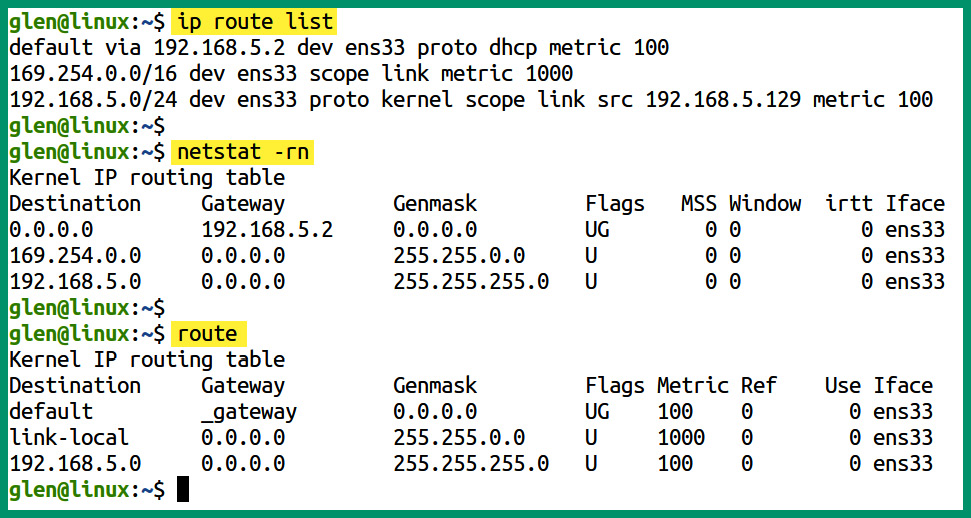
Figure 4.38 – Routing table of a Linux-based device
As shown in the preceding screenshot, the ip route list command displays the network routes on the local device and indicates that the default gateway is 192.168.5.2. These are connected using the ens33 interface. The netstat –rn command displays the routing table. This is similar to a Windows routing table. Lastly, the route command displays the routing table as well, but it does not specify the IP address of the gateway.
Implementing a default gateway such as a router on the network allows end devices to forward their messages to the default gateway when their local routing table does not have a route for the destination of a packet. The default gateway is usually a Layer 3 device, such as a router, that connects the LAN of an organization to the internet.
The default gateway is configured with a default route that allows the router to inspect the destination IP address within each packet that is received from internal clients on the network. If the router receives a packet with a destination IP address that doesn’t exist within the private networks of the organization, the router will forward it to the ISP’s router on the internet.
In this section, you learned how to identify and describe the functionality of various types of addresses on a network. In the next section, you will learn how IPv4 and IPv6 can coexist on the internet.
Delving into IPv6 concepts
IPv4 and IPv6 addresses exist within different spaces and cannot natively communicate with each other. To help ensure devices that exist on both IPv4 and IPv6 networks can communicate with each other, various IPv6 technologies allow both versions of IP to coexist. Within this section, you will learn about each technique that allows the coexistence of IPv4 and IPv6 on networks.
Tunneling
While IPv4 is currently dominating most parts of the internet, there are many IPv6 public networks. However, not all organizations have adapted and implemented IPv6 networks within their company. One of the major concerns about having two different versions of IP on the internet or within an organization is that these two versions cannot communicate with each other natively. Simply put, if a device such as a computer is configured with an IPv6 address, it will not be able to communicate with devices on an IPv4 network. Furthermore, routers will not be able to transport an IPv6 packet over an IPv4 network without the help of tunneling.
Tunneling allows IPv6 packets to be transported over an IPv4 network. The forwarding router is responsible for encapsulating the IPv6 packet inside an IPv4 packet before sending it over the IPv4 network. This type of tunneling is referred to as 6to4 tunneling. 4to6 tunneling, on the other hand, allows an IPv4 packet to be encapsulated within an IPv6 packet so that it can be transported over an IPv6 network.
Dual stack
Another method for IPv4 and IPv6 to coexist within private and public networks is to implement dual stacking. Dual stacking both IPv4 and IPv6 addresses on the same NIC of an end device or interface of a networking device such as a router will allow the device to communicate efficiently on both IPv4 and IPv6 networks. If the device has sent a message to a host on an IPv4 network, it will use the IPv4 address that’s configured on its local NIC or interface. If the device has to send a message to a host on an IPv6 network, the process is quite simple as it will use the IPv6 address that’s configured on the local NIC or interface.
The following screenshot shows the wireless network adapter of a Windows 10 computer:
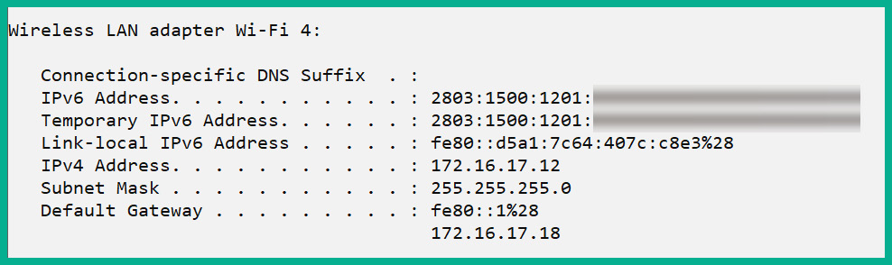
Figure 4.39 – Dual stack NIC
As shown in the preceding screenshot, this is a wireless NIC of a Windows 10 computer that has been configured/assigned with both IPv4 and IPv6 addresses. The dual stack allows this network adapter on the device to communicate with both devices on IPv4 and IPv6 networks simultaneously.
Translation
As you learned earlier in this chapter, NAT allows a router to translate the source private IPv4 address into a public IPv4 address before forwarding the packet out on the internet. Network Address Translation 64 (NAT64) allows devices within an IPv6 network to communicate with hosts on an Iv4 network using an address translation that’s similar to traditional NAT for IPv4 networks and devices. NAT64 is configured on routers to translate IPv6 addresses into IPv4 addresses, which allows IPv6-enabled devices to communicate with IPv4 hosts and vice versa.
Router advertisement
Devices on an IPv6 network automatically obtain a GUA IPv6 address using ICMPv6 messages. Whenever an IPv6-enabled device such as a computer is connected to an IPv6 network, it sends a Router Solicitation (RS) message to the network to discover any IPv6 routers. An IPv6-enabled router responds with a Router Advertisement (RA) message, which is used to inform the host on the network how to obtain a GUA IPv6 address.
Furthermore, the RA message provides the following network information to the client:
- The network prefix and the prefix length of the address
- The default gateway IPv6 address for the network
- The DNS server IP addresses and domain name
Additionally, the RA messages provide the following methods for configuring a GUA IPv6 address for a client on the network:
- Stateless Address Autoconfiguration (SLAAC)
- SLAAC with stateless DHCPv6
- Stateful DHCPv6
Next, you will learn about SLAAC and the methods used for configuring a GUA IPv6 address.
Stateless Address Autoconfiguration (SLAAC)
SLAAC allows devices on a network to be configured with a GUA IPv6 address without the need for a Dynamic Host Configuration Protocol v6 (DHCPv6) server. DHCP is a commonly used network protocol and allows a DHCP server to automatically distribute IP addresses to devices on a network. The DHCPv6 server distributes IPv6 addresses to the client.
However, in some IPv6 networks, there are no DHCPv6 servers available to provide IPv6 addresses to clients on the network. The following is the process of a client obtaining a GUA IPv6 address using SLAAC on an IPv6 network:
- A client on the network sends an RS message to seek any IPv6-enabled routers.
- The IPv6-enabled router responds with an ICMPv6 RA message and provides the network prefix and the prefix length.
- The client uses the EUI-64 process to convert its 48-bit MAC address on the local NIC to create a 64-bit Interface ID. The 64-bit Interface ID is appended to the end of the 64-bit network prefix to create a 128-bit GUA IPv6 address for the client.
Additionally, the RA message from the router can indicate to the client to use both SLAAC and stateless DHCPv6 to obtain a GUA IPv6 address. In this situation, the RA messages inform the client device of the following instructions:
- First, use SLAAC to create its own GUA IPv6 address.
- Second, use the router’s IPv6 Link-Local address as the default gateway for the network. The router’s IPv6 Link-Local addresses are set as the source addresses within the RA message from the router to the client.
- Lastly, use the stateless DHCPv6 server to obtain the DNS server addresses and domain names only. The stateless DHCPv6 server does not provide the IPv6 address, prefix length, or the default gateway.
Another method for a client to receive an IPv6 address from the network is using a stateful DHCPv6 server. A stateful DHCPv6 server has similar functionalities to a traditional DHCP server on an IPv4 network as it provides the following configurations to clients:
- GUA IPv6 address
- Prefix length
- DNS server addresses
- Domain name
While using a stateful DHCPv6 server on a network, the RA messages from the router provide the default gateway address to clients. The router’s IPv6 Link-Local address is included within the RA message as the source address.
Having completed this section, you have explored the characteristics and use cases of various IPv4 and IPv6 address types on a network. In the next section, you will learn how to configure IP addresses on various types of devices.
Configuring IP addresses
In this section, you will gain the hands-on skills needed to configure and assign IPv4 and IPv6 addresses on various devices such as Windows and Linux operating systems, as well as a Cisco IOS router.
Windows operating system
In this hands-on exercise, you will learn how to configure an IP address on a Windows 10 operating system. To get started with this exercise, follow these steps:
- First, on a Windows 10 device, click on the start icon that’s located at the bottom-left corner of the desktop.
- Next, within the Windows Search bar, enter Control Panel and click on the application.
- Next, within the Windows Control Panel, click on Network and Internet, as shown in the following screenshot:
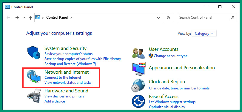
Figure 4.40 – Control Panel
- Next, within the Network and Internet menu, click on Network and Sharing Center, as shown in the following screenshot:
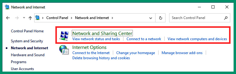
Figure 4.41 – The Network and Internet menu
- Next, within the Network and Sharing Center area, click on Change adapter settings, as shown in the following screenshot:
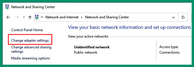
Figure 4.42 – Network and Sharing Center
- Within the Network Connections menu, you will see a list of wired and wireless network adapters. Right-click on your network adapter and select Properties, as shown in the following screenshot:
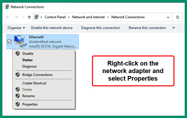
Figure 4.43 – Network adapters
- On the network adapter’s properties window, you have the option to change the settings of IPv4 and IPv6 addresses. To modify the IPv4 settings on the adapter, select Internet Protocol Version 4 (TCP/IPv4) and click on Properties, as shown in the following screenshot:
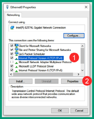
Figure 4.44 – Modifying IPv4 settings
- Next, the IPv4 Properties window will appear. By default, the network adapter is configured to automatically obtain an IP address, subnet mask, default gateway, and DNS server addresses from a DHCP server on the network. To set a static IP address that does not change, you can modify the various options, as shown in the following screenshot:
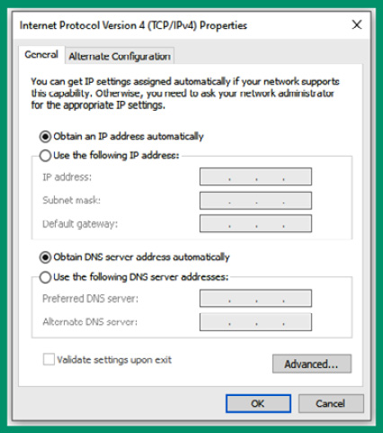
Figure 4.45 – IPv4 settings
If you modify the configurations on the network adapter, ensure you click on OK to save and apply the setting on the network adapter.
- After changing the IPv4 and/or IPv6 settings on the network adapter, click on the Windows icon on the taskbar to open the Start menu and enter cmd or Command Prompt to quickly find and open the Windows Command Prompt.
- Once the Command Prompt area is open, use the ipconfig and ipconfig /all commands to view the IP addressing information on the network adapter, as shown in the following screenshot:
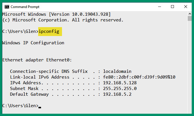
Figure 4.46 – Verifying IP configurations
As shown in the preceding screenshot, the ipconfig command helps network professionals quickly determine the IP address, subnet mask, and default gateway of a Windows device.
Tip
These steps can be achieved by using the netsh interface ip set address name=”Packt1” static 192.168.5.128 255.255.255.0 192.168.5.2 command in the Windows Command Prompt.
Having completed this exercise, you have gained the hands-on skills needed to configure and modify IP addresses on a Windows operating system. Next, you will learn how to modify the network adapter settings on a Linux-based device.
Linux operating system
In this hands-on exercise, you will learn how to configure and modify the IP address settings on a network adapter on a Linux-based operating system such as Ubuntu Desktop. To get started with this exercise, follow these steps:
- On Ubuntu Desktop, click on the power icon at the top-right corner to expand the drop-down, then click on Settings, as shown in the following screenshot:
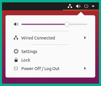
Figure 4.47 – Opening the Settings menu
- Next, within the Linux Settings menu, select Network and click on the gear icon next to the wired network connection, as shown in the following screenshot:
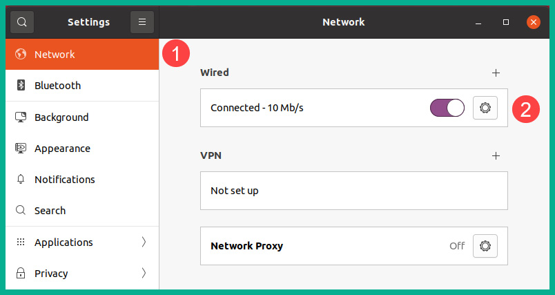
Figure 4.48 – The Settings menu
- Next, within the adapter settings, select IPv4 to change the IPv4 address, subnet mask, and DNS server addresses and create static routes, as shown in the following screenshot:
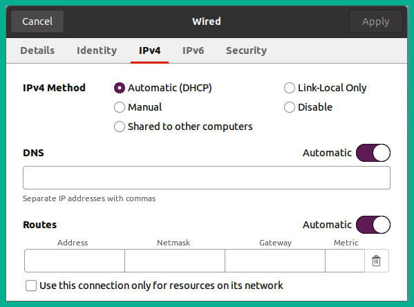
Figure 4.49 – IPv4 settings
If you modify any settings on the network adapter, ensure you click Apply to apply the configurations to the adapter of the Linux machine.
- Next, you can open the Terminal area and use the ip addr command to determine the number of network adapters and the IP addresses that have been assigned to them, as shown in the following screenshot:
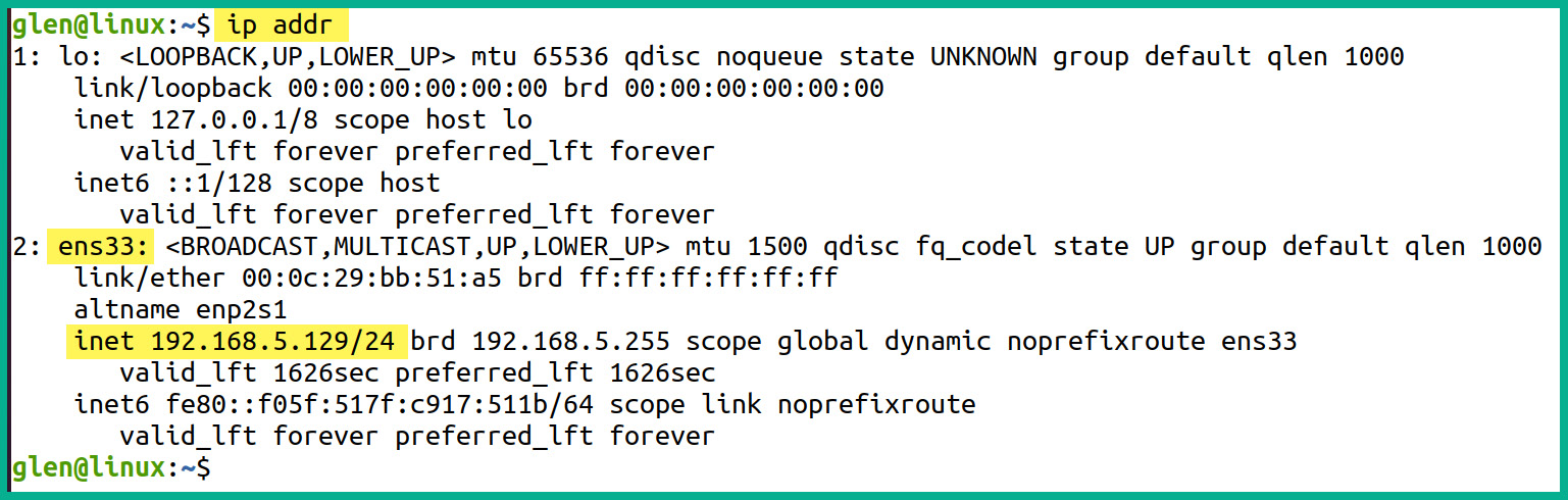
Figure 4.50 – Verifying IP addresses
As shown in the preceding screenshot, the ens33 network adapter on the Ubuntu machine has been assigned the 192.168.5.129/24 address.
Important note
Some networking tools may not be available within the Linux operating system. Simply use the sudo apt update and sudo apt install net-tools commands to install additional networking tools on the operating system.
- Lastly, the ifconfig command provides a list of network adapters on the local machine and the IP addresses, as shown in the following screenshot:
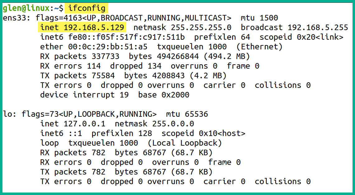
Figure 4.51 – Checking IP addresses and network adapters
As shown in the preceding screenshot, the ifconfig command provides meaningful information to network professionals to determine the current IP addresses on the available network adapters on the device.
Having completed this exercise, you have gained the hands-on skills to modify the IP address configurations on a Linux operating system. Next, you will learn how to configure IPv4 and IPv6 addresses on a Cisco IOS router.
Cisco IOS router
In this exercise, you will learn how to configure IP addresses on an interface on a Cisco IOS router. To get started with this exercise, follow these steps:
- Connect to the Cisco IOS router using a console cable between the computer and the console port on the router, or connect to the router via remote access.
- Next, use the following commands to configure an IPv4 address on a specific interface on the device:
Router> enable
Router# configure terminal
Router(config)# interface gigabitEthernet 0/1
Router(config-if)# ip address 192.168.1.1 255.255.255.0
Router(config-if)# no shutdown
Router(config-if)# exit
- Next, to configure an IPv6 address on a Cisco IOS router, use the following commands:
Router> enable
Router# configure terminal
Router(config)# ipv6 unicast-routing
Router(config)# interface gigabitEthernet 0/1
Router(config-if)# ipv6 address 2001:1234:4567:89AB::1/64
Router(config-if)# no shutdown
Router(config-if)# exit
Router(config)# exit
- Next, to view the IPv4 configurations on the GigabitEthernet 0/1 interface, use the show ip interface command, as shown in the following screenshot:
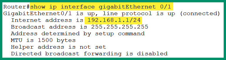
Figure 4.52 – Verifying the IPv4 address on an interface
- Next, to view the IPv6 address on an interface, use the show ipv6 interface command, as shown in the following screenshot:
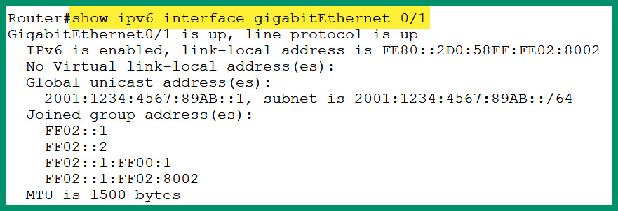
Figure 4.53 – Verifying the IPv6 address on an interface
Having completed this exercise, you have learned how to configure both IPv4 and IPv6 addresses on an interface on a Cisco IOS router.
Summary
In this chapter, you have gained a solid understanding of the need for logical addressing on a network and have discovered both the IPv4 and IPv6 address spaces. You learned about the importance of NAT to help preserve the IPv4 public address space while allowing devices on a private network to communicate with hosts on a public network. Furthermore, you have gained the hands-on skills to convert IP addresses between binary and decimal. Additionally, this chapter covered the characteristics of various IPv4 and IPv6 address types and their role on a network.
I hope this chapter has been informative for you and is helpful in your journey toward learning networking and becoming a network professional. In the next chapter, Chapter 5, Applied IPv4 Subnetting, you will gain hands-on skills as a network professional to break down network blocks into subnetworks using the technique of subnetting.
Questions
The following is a short list of review questions to help reinforce your learning and help you identify areas that may require some improvement:
- Which of the following statements is true?
A. There are 48 bits in a MAC address
B. There are 48 bits within an IPv4 address
C. There are 64 bits within an IPv6 address
D. There are 32 bits within a MAC address
- Which of the following is the default subnet mask for the 172.30.1.45 IP address?
A. 255.0.0.0
B. 255.25.2555.0
C. 255.255.0.0
D. 255.255.255.128
- Which of the following classes does the 172.14.9.64 IP address belong to?
A. Class A
B. Class C
C. Class E
D. Class B
- Which of the following IP addresses belongs to the RFC 1918 list of addresses?
A. 172.29.0.45
B. 172.32.4.67
C. 172.15.76.69
D. 172.14.100.45
- Which type of address translation allows network professionals to map multiple private IP addresses to a single public address?
A. Static NAT
B. Dynamic NAT
C. PAT
D. All of the above
- Which of the following addresses is not a valid IPv4 address?
A. 129.34.67.25
B. 185.56.32.87
C. 118.454.45.23
D. 23.78.23.99
- Which of the following is not a valid IPv6 address?
A. 2001:0DD8:0000:1111:0000:0000:0000:0200
B. 2001:0DE8:0000:1111:0000:0000:0000:0200
C. 2001:0DF8:0000:1111:0000:0000:0000:0200
D. 2001:0DG8:0000:1111:0000:0000:0000:0200
- Which of the following commands should you use to determine the current IP address configurations on a Windows operating system?
A. ipconfig
B. ifconfig
C. ip addr
D. route print
- Which of the following is a EUI-64 address?
A. 2001:DB8:0:1111:FE99:47FA:FE75:CEE0
B. 2001:DB8:0:1111:FE99:47FF:FE75:CEE0
C. 2001:DB8:0:1111:FE99:47FB:FE75:CEE0
D. 2001:DB8:0:1111:FE99:47FC:FE75:CEE0
- Which of the following techniques translates an IPv6 address into an IPv4 address?
A. NAT
B. PAT
C. NAT overload
D. NAT64
Further reading
To learn more about the topics that were covered in this chapter, check out the following links:
- Number Resources: https://www.iana.org/numbers
- 4 IP Configuration Commands Every SysAdmin Should Know: https://www.comptia.org/blog/ip-configuration-commands
- Talk Tech to Me: 9 Common Linux Network Commands: https://www.comptia.org/blog/linux-network-commands
- What is NAT?: https://www.comptia.org/content/guides/what-is-network-address-translation