
2
Network Topologies and Connections
Designing a network to provide scalability, security, and redundancy with fault tolerance is essential to any network design and model. As an aspiring network professional, it’s important to learn the building blocks of designing an optimal and resilient network infrastructure for the growing demand of organizations to support their business services and users. Understanding how network topologies can affect traffic flow within an organization is important to gain a solid understanding of designing a suitable network for any organization.
During this chapter, you will explore various network layouts and how they affect traffic flow within an organization. Next, you will explore various network types and devices that are interconnected to expand and share network resources over large geographic distances. Furthermore, you will understand how organizations and residential customers can connect to the service provider’s network.
In this chapter, we will cover the following topics:
- Understanding network topologies
- Discovering network types
- Identifying service-related entry points
- Comparing provider links
Let’s dive in!
Understanding network topologies
Network professionals design, implement, maintain, and troubleshoot networking technologies to ensure organizations can share resources between their users and devices within their company. Some networks are small, such as those within homes. These small networks usually have a few networked devices such as computers, smart appliances, Internet of Things (IoT) devices, and a couple of networking devices, such as a wireless router to create a wireless network and an Internet Service Provider (ISP) modem to provide internet service.
While small networks are very common to many users, within an organization, there are lots of devices based on the number of users, networks, and networking services within the company. Within an organization, there are many computers, laptops, servers, and smart/IoT devices. To interconnect all the devices within an organization, the company invests in purchasing many networking switches, routers, access points, and security appliances.
Important note
A network switch allows end devices such as computers, printers, and servers to connect to the actual organization’s network. A router is a network device that interconnects two or more different networks together.
Interconnecting networking devices such as switches and routers seems simple as you can use a networking patch cable to make a physical connection between each device. However, if you interconnect networking devices without using a proper network design with industry best practices, you’ll just be setting yourself up for a lot of future networking issues. As an aspiring network professional, it’s very important to understand the various layouts of networking devices that are used to build a network. This idea of creating a layout of a network is commonly referred to as a topology or network topology.
Network topologies are used to help IT professionals understand how systems and devices are interconnected and to identify areas of improvement or where an issue may exist. Networking topologies can be described as physical or logical. A physical network topology contains a high-level overview showing the actual arrangement and placement of devices within an organization, such as the geographic location, such as city, as well as building names and floor and closet names. The physical network topology also shows the types of network connections and connectors since they are used to represent the type of network cables and how they are connected between devices within the organization.
The following diagram shows a simple example of a physical network topology:

Figure 2.1 – Physical network topology
The logical network topology is a low-level diagram that focuses on the technical details of the network, such as the IP addresses and schemes, which demonstrate how data flows across the organization. The logical network topology diagram provides details about the different devices, such as switches, routers, and firewalls.
The following diagram shows an example of a logical network topology:

Figure 2.2 – Logical network topology
Network topology diagrams are not too difficult to create once you have a clear understanding of the network infrastructure within your organization. Without network topology diagrams, it can become challenging to troubleshoot an issue since the network professional doesn’t understand the topology without a network diagram. Network diagrams should always be updated whenever a change occurs on the network. A change can be anything such as an upgrade, implementing new technologies and devices, and replacing or even decommissioning a device.
The following are some resources you can use to draw network topology diagrams:
- Diagrams.net: https://www.diagrams.net/ (free)
- LibreOffice Draw: https://www.libreoffice.org/discover/draw/ (free)
- Microsoft Visio: https://www.microsoft.com/en-us/microsoft-365/visio/flowchart-software (commercial)
Many diagram and flowchart applications are used by many professionals within various industries. I recommend evaluating different diagram applications to determine which works best for you and meets your requirements. Some people may prefer a free application, while others may prefer a commercial product; each has its advantages and disadvantages. Keep in mind that your network diagrams should always be clear and easy to understand by anyone who is viewing them. In the past, I’ve seen diagrams created by networking professionals who have a lot of knowledge and skills, but due to less focus on soft skills such as communication and presentation, their diagrams were a bit challenging to understand. As an aspiring networking professional, it’s important to have the essential soft skills and a creative imagination.
In the next section, you will discover the key characteristics of various types of network topologies.
Types of network topologies
A network topology defines the layout of how devices such as computers and networking devices are interconnected to allow traffic to flow within an organization. There are various types of network topologies, and each has its advantages and disadvantages. In this section, you’ll discover various physical topologies.
Bus
The bus topology is a very old and legacy network topology that is no longer being used on modern networks. This type of network topology was designed to use a single networking cable as the main backbone of the entire network. This single backbone allowed nodes such as computers to connect to and access any resource on the network.
The following diagram shows an example of a traditional bus topology:
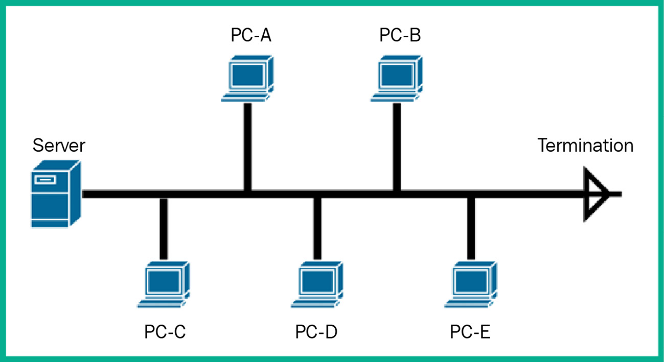
Figure 2.3 – Bus topology
As shown in the preceding diagram, all nodes are connected to the same networking cable (backbone), which allows each node to access the resources on the server or those that are shared from one node to another. On each end of the backbone networking cable, some terminators are installed to terminate or ground the cable if there are any unwanted electrical signals on the wire. Remember, computers and networking devices produce electrical signals that travel along a wire, such as a networking cable between nodes and devices. If there are additional or unwanted electrical signals on the wire and there’s no place to discharge those signals, it can affect the devices connected to the networking cable.
In Shared Ethernet, the message is sent to a specific destination Media Access Control (MAC) address. Each node on the physical segment receives the message but only the Network Interface Card (NIC) whose MAC address matches the destination MAC address in the destination section of the Ethernet frame will accept the message (packet). All other NICs will discard this message (packet). This is true if the NICs are in non-promiscuous mode, which is the default mode.
The following diagram shows an example of a host sending a Shared Ethernet message:

Figure 2.4 – Shared Ethernet on a bus topology
As shown in the preceding diagram, PC-A sends a message to PC-D, in a bus topology where all devices receive the message. Only PC-D will accept and process the message received from PC-A, while all other recipients of the message will discard it. This causes a lot of overhead processing for each host and excessive traffic on the network.
While the bus topology seems to be quite simple, there are a few drawbacks that do not make it suitable to support modern-day organizations. As more than one device attempts to access the network and send messages, this creates a lot of contention on the network as only one device can send a message at a time. Imagine if an organization is using a bus topology as their preferred network topology and many devices are attempting to communicate with each other at the same time – there will be a lot of contention to access the physical network. If multiple devices broadcast their message, network collisions can occur, where the packets become corrupted on the network, which causes a device to retransmit the message over the network.
The following diagram shows an example of a possible network collision when two nodes transmit:

Figure 2.5 – Network collision
Another drawback of using the bus topology is its usage of a single backbone cable; there is no redundancy if a network failure was to occur. If there’s a break at any point along the backbone network cable, this will result in an entire network outage where devices will not be able to communicate. Furthermore, this type of network topology has a lot of limitations for organizations that are growing. The bus topology does not support scalability or the ability to grow.
Now that you have learned about the key characteristics of the bus topology, let’s explore the fundamentals of the ring network topology.
Ring
The ring topology is another older, legacy network topology that is no longer used within modern organizations. This type of network topology is designed to interconnect end devices such as computers in a ring format, where one host is connected to another host, and so on to create an actual ring.
The following diagram shows an example of a traditional ring topology:

Figure 2.6 – Ring topology
As shown in the preceding diagram, each host (device) is interconnected to another host to create the ring topology. Within this type of topology, communication only occurs in a single direction. Therefore, if PC-A wants to communicate with another device, the message is sent in a single direction only and this method is applied to all devices on the network.
There’s a dual ring topology that has two logical ring connections on each node on the network. The dual ring allows communication to occur in opposite directions on each ring. Here, one ring will allow traffic to flow clockwise only, and counterclockwise in the other ring.
The following diagram shows an example of a dual ring topology:

Figure 2.7 – Dual ring topology
While the ring topology seems simple, there are a few drawbacks to using this type of topology. Since communication occurs in a single direction, the message from the sender is passed along the way to each host on the network until it arrives at the intended destination host. Since the message of a sender passes to each host toward the destination, only one host can send a message at a time on the network. Since all nodes are interconnected, if a node within the ring topology is not available on the physical network, the entire network goes down, and the devices will not be able to communicate.
Now that you’re familiar with the ring topology, let’s learn about the star topology.
Star
The star topology is a common network topology used on many networks within organizations. The star topology allows the hosts to connect to a single networking device such as a switch. This topology ensures that if any host on the network wants to send a message to another host, the sender will forward the message to the network switch, which forwards the message to the intended destination host.
The following diagram shows a star topology:

Figure 2.8 – Star topology
As shown in the preceding diagram, the switch functions as the network intermediary device to forward messages between a sender and receiver on the network. If one host on the network is offline or unavailable, the entire network is not affected except the bus and ring topologies, so the hosts can continue to send and receive messages simultaneously. In the star topology, if the central networking device such as the switch goes down or becomes unavailable, the entire network or all the connected hosts to the switch will be affected and won’t be able to communicate.
The following diagram shows a visual representation of a network outage in a star topology:
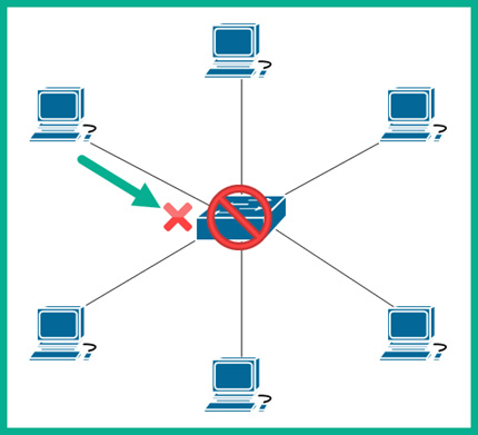
Figure 2.9 – Network outage
As shown in the preceding diagram, there isn’t any redundancy built into the simple star topology. Since the switch is not available, all the connected hosts are affected. In this book, you will learn how network professionals implement fault tolerance and redundancy to ensure network services and resources are always available to users.
When working with a star topology, it’s easy to support scalability for organizations that are increasing the number of devices that can connect to their networks. This is one of the major benefits of using a star topology – its support for scalability.
The following diagram shows how a star topology supports scalability:

Figure 2.10 – Scalability in a star topology
As shown in the preceding diagram, if the organization wants to connect more hosts to the network, the network professional can connect another switch that will be able to support more hosts. When designing a network for an organization, scalability is one of the many factors that that networking professionals need to consider. Imagine if a network professional designed and built a network without the support to grow; if the organization needs to connect new devices to the network, there won’t be any support. Thus, the network professional will need to redo the network design to support a growing organization. Furthermore, scalability does not only apply to the increase of connected devices – it needs to support the increase of network traffic and traffic types too.
Now that you have gained the fundamental knowledge of star network topologies, let’s explore mesh topologies.
Mesh
Mesh topologies are currently used within various organizations or parts of their networks. In a mesh topology, each device within the network is connected to all other devices, creating a physical and logical mesh design. A mesh network topology provides full redundancy for traffic flow between any source and any destination as all devices are interconnected.
The following diagram shows an example of a mesh topology:

Figure 2.11 – Mesh topology
As shown in the preceding diagram, each router is connected to all other routers, thus creating multiple and redundant paths within the network. If one path goes down or becomes unavailable, there are multiple other paths available to forward network traffic between a source and a destination. Redundancy is another key factor network professionals need to consider when designing a network for an organization. Without redundancy, a network failure can result in the unavailability of network resources to users and the organization.
While having multiple redundant connections from one node to all other nodes in a mesh topology, this type of network topology can be complex to troubleshoot if an issue should occur due to the number of available paths. Additionally, if a new node joins the topology, the number of connections increases, which means there’s also an increase in the cost to maintain the network. The formula to determine the number of links is N(N-1)/2. For example, if there are five devices, the total number of links is 5(4)/2 = 20/2 = 10. Adding just one additional device means there are 15 total links: 6(5)/2 = 30/2 = 15.
The following diagram shows an example of the number of connections needed as the network grows:

Figure 2.12 – Mesh network
As shown in the preceding diagram, as more nodes join the mesh topology, the number of required connections increases between each device. As a result, if an organization is implementing a mesh network design to interconnect all their branch offices, similar to what’s shown in the preceding diagram, the organization needs to pay the ISP for each Wide Area Network (WAN) circuit (connection) between the branch routers. As you can imagine, the more connections/links there are in a mesh topology increases the expenditure of the organization and the complexity of configuring the nodes, such as routers, within the network. While the mesh topology provides the most redundancy, it becomes quite costly and complex as the network increases in size.
While the mesh topology has its advantages and disadvantages, organizations need to weigh the difference to determine whether it is the best design to fit their needs. Next, you will learn about the characteristics of the hybrid network topology.
Hybrid
Within many organizations, you will commonly find a mixture of many different network topologies implemented within the company. As an organization grows, so does the network to support the additional number of connected devices and new services. The hybrid topology is a combination of two or more different topologies that are interconnected to create a unified network.
The following diagram shows an example of a hybrid topology:
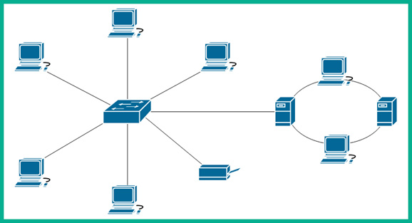
Figure 2.13 – Hybrid topology
As shown in the preceding diagram, the network consists of both star and ring topologies. Often, network professionals use different combinations of network topologies within their organizations to interconnect end devices such as computers and servers, as well as interconnect their branch offices together to share resources.
Now that you're aware of the characteristics of the hybrid topology, next, you will learn about the hub and spoke topology.
Hub and spoke
The hub and spoke topology is designed to provide a centralized node that acts as the main hub for all other nodes to interconnect. The hub on this topology acts as the central referencing point for all traffic between other nodes on the network. Each node is connected to the hub and these connections are referred to as spokes. This network topology does not allow nodes to directly connect; rather, all network traffic is sent through the hub within this topology, which is responsible for forwarding traffic to another node on the network.
The following diagram shows an example of a hub and spoke topology interconnecting different locations:

Figure 2.14 – Hub and spoke topology
As shown in the preceding diagram, the organization has one main office that will function as the headquarters that contains all the servers, while three remote branch offices will be used to provide services to customers are various geographic locations. Whenever a user or device needs to access a resource at another branch location, the traffic is sent to the main officer router (hub), which then forwards the traffic to the destination network.
The following diagram shows one branch office sending a message to another branch office:

Figure 2.15 – Communication over a hub and spoke network
As shown in the preceding diagram, there are no direct connections between each spoke on the network. All spokes (branch offices) have to forward their traffic through the hub (main office), which is responsible for inspecting and routing network traffic to their destination.
The hub and spoke topology is commonly used by medium-sized and large organizations to interconnect their remote branch offices to their main office location. This topology is a cost-efficient design that allows organizations to save on internet subscription fees and improve their security monitoring.
Having completed this section, you have learned how to identify each type of network topology within the networking industry. In the next section, you will discover various network types and their characteristics.
Discovering network types
While there are many network topologies within the networking industry, there are also many network types, and each has characteristics. Network types are used to define the geographic boundary or limitation of a network and help network professionals understand the relationship between the connected devices within the network.
In this section, you will discover the key characteristics of various network types and gain a strong understanding of how each network type may differ from the others.
Peer-to-peer
In a peer-to-peer model, each client is logically connected and shares their resources with other clients on the network without the need for a centralized, dedicated server to provide the resources. If a client within the peer-to-peer network has a printer, that client can be configured to share the printer as a resource with other clients on the network. The client that is sharing the printer or resource becomes a server, while the others hosts (computers) on the network are clients that are accessing or requesting the resource.
The following diagram shows a logical overview of a peer-to-peer network model:

Figure 2.16 – Peer-to-peer model
As shown in the preceding diagram, there is no centralized management of any network resource or service. As a result, peer-to-peer networking does not support scalability well and may change to ensure all the clients on the network have access to the resources. Peer-to-peer networks are typically implemented as workgroups in many small organizations.
A real-world example of a peer-to-peer network is sharing files using a torrent. A torrent, or torrenting, allows a user to share files on their computer across a network such as the internet. A user who has a file to share with others uses a torrent manager application to create a torrent file and shares the torrent file with other users on the internet. The torrent file contains information about the file, file type, size, and so on, so when a user adds the torrent file to their torrent manager, the manager seeks the location of the file over the internet and establishes a peer-to-peer logical connection to all nodes that have the torrent file active on their computers/devices. In the world of torrenting, seeds or seeders are the computers that have the complete file on their device and share it with others to download. On the other hand, leeches or leechers are devices that download the file from each peer, preferably the seeds, until it reaches 100% download completion.
However, on a peer-to-peer network, there’s no centralized management of resources, and security is a huge concern as each node is responsible for managing its security posture. Next, you will learn about the client-server model.
Client-server
The client-server network model contains dedicated devices that provide a resource or service to hosts on a network. These devices are referred to as servers. A server can be any device running an application that allows other hosts on the network to access the resources stored or being provided by the server.
The following diagram shows an example of a client-server model:

Figure 2.17 – Client-server model
As shown in the preceding diagram, the server can be configured as a file server to centrally store files and data for other devices and users on the network. The clients on the network are the devices that are requesting a service or resource. In a client-server model, scalability allows the network to grow while ensuring the resources are centrally accessible by all clients on the network. This is a major advantage of using a client-server model compared to a peer-to-peer networking model.
Next, you will learn about the fundamentals of a personal area network (PAN).
Personal area network
A PAN is a small network that is usually created by a user to interconnect their devices, such as a laptop, smartphone, wireless headphones, or a wireless printer. A user can set up a wired or wireless network to ensure their devices are connected to the same network. However, keep in mind that this type of network is not designed to connect to a larger network with other devices.
The following diagram shows an example of a PAN network:

Figure 2.18 – Personal area network
As shown in the preceding diagram, the user creates a small network to allow their devices to share resources within a very short distance. A real-world example of a PAN is connecting a laptop and smartphone to a wireless printer at home to print pictures. Another example is establishing a Bluetooth connection between a smartphone and another Bluetooth-enabled device to share files.
Within a PAN network, each device is responsible for managing its security. Next, you will learn about the characteristics of a local area network (LAN).
Local area network
A LAN is a small network that exists within a single geographic location, such as within a building. A LAN allows all devices within an office location or building to be interconnected and share resources. Imagine starting an organization where you’ve acquired a building to provide office spaces for your employees, computers, and servers. Interconnecting all the devices, such as the computers, servers, and network printers, into a single physical network creates a LAN that allows everyone and all devices on the same network to easily share resources.
The following diagram shows an example of a LAN network type:

Figure 2.19 – LAN network model
As shown in the preceding diagram, the network contains a few workstations that are used by the employees within a small office, and each end device, such as a computer and printer, is connected to the network switch. The switch connects to the router, which functions as the default gateway to forward traffic from the internal network to a remote/foreign network such as the internet.
Important note
Without a default gateway device such as a router at the edge of a logical IP network, clients will not be able to communicate with remote networks or devices.
The router connects to the firewall to filter inbound and outbound traffic between the internal network and the internet. All the devices shown within the preceding diagram represent a LAN as they are all interconnected and within a single, small geographic location.
While LANs are created for organizations that only reside in a single location, some organizations will grow and open new branch offices in different geographic locations and will need to extend their network. Next, you will learn about extending a LAN over a large geographic distance.
Wide area network
A wide area network (WAN) allows organizations to extend their LAN and its resources over a large geographic distance. Why do we need a WAN? Business owners will usually create an organization with a single office location; as the company grows the demand for their products and services, so does the company. When a company starts with a single office location, a LAN is created within the building or office space to interconnect all devices and share resources such as files, and even the network printer. As the demand for the organization’s products and services increases, the business owner(s) will hire more employees to ensure the demand is met while improving the business processes and so on.
As time goes by, the organization will grow and create new remote office locations within other cities or countries to support its customers. The organization may have all its servers located at its main office and want to share access with employees who are working at a remote office. Using a WAN allows the organizations to extend their LAN from their main office over a large geographic distance to each of the remote offices as needed.
The following diagram shows a WAN interconnecting two office locations:

Figure 2.20 – WAN
As shown in the preceding diagram, the WAN connection is established by a Managed Service Provider (MSP) or an Internet Service Provider (ISP). The service provided will implement the networking infrastructure throughout a city or country to support the demand for managed networking services and solutions. Usually, an organization that wants to interconnect its branch offices will contact various service providers for a consultation and the cost of the WAN services. The organization chooses the service provider that meets its business needs. The MSP or ISP is responsible for establishing and maintaining the WAN network for the organization. All traffic sent into a WAN connection by an organization remains private as the traffic passes through the service provider’s network infrastructure. WAN solutions are managed services from service providers as they are responsible for the configuration, deployment, maintenance, and troubleshooting of the service on behalf of their customers.
What if an organization has multiple branch offices? How can internet services be established for all locations of the company? One solution is to implement a WAN solution and an internet service at each office location. The WAN solution will be used to share the network resources between branches, while the internet services provide access to the online services and resources that are outside the company’s network.
The following diagram shows a WAN connection being used to create a hub and spoke topology to connect each remote office to the main office location; each office location has a dedicated internet connection:

Figure 2.21 – Hub and spoke WAN connection
As shown in the preceding diagram, the organization has a hub and spoke topology for the WAN solution, while each office location has a dedicated internet service. While this setup may seem appropriate if the branch offices were located within different countries, where each country has its own ISP to supply internet services, if each branch office is located within the same country, it’s not cost-efficient as the organization is charged for the internet service at each branch location, including the main office.
A better solution for an organization that has multiple branch offices within the same country is to create a hub and spoke topology for the WAN solution and implement a single internet connection at the main office. The internet service can be redistributed within the WAN connected to each branch router.
The following diagram shows an example of using a hub and spoke topology for a WAN solution while redistributing the internet to each branch office within the same country:

Figure 2.22 – Hub and spoke WAN topology with internet connectivity
As shown in the preceding diagram, the WAN connections are established between the main office and each branch office; the internet service is implemented at the main office only. Network professionals can configure the networking devices at the main office to redistribute the internet service through the WAN connection to each branch office. This design allows an organization to save a lot of money on their internet services when the branch offices are usually in the same country.
Important note
It is possible to redistribute internet services through a WAN connection to a branch office in another country, but the latency (response time) and network performance will not be optimal.
Next, you will learn about a network type that covers a city.
Metropolitan area network
Around the world, there are very large cities with many people, businesses, and fun things to do all day. In large cities, some organizations have multiple branch offices within the same city and need interconnectivity between their offices to share resources with employees. Using a metropolitan area network (MAN), a service provider can interconnect all the branch offices of a single company within the same city. Some cities offer a MAN to residences as a low-cost, high-speed connection to the internet. These MANs can be used to incentivize residents to move to that city.
The following diagram shows an example of a MAN network type:

Figure 2.23 – Metropolitan area network type
As shown in the preceding diagram, a MAN is used to interconnect the branch offices of a single company within the same city. Keep in mind that a MAN is limited to a single city and organization.
Next, you will learn about a wireless network type that bridges a wired and wireless network topology.
Wireless local area network
Years ago, networks within organizations consisted of computers, servers, and networked devices that were connected using a wired connection. In the era of mobile computing, each person can have a mobile, portable device such as a laptop computer that contains all the essential components of a desktop computer but in a smaller and compact form factor. People no longer need to sit stationary at a single location to do work on their computers – they can work or learn using their laptops at any location that’s comfortable and convenient to them.
As the mobile and IoT industry started, the demand for mobile computing and smart devices increased. This led to organizations implementing wireless networking infrastructure to support the need to connect wireless-capable devices onto their corporate network to share the same resources as the wired devices.
Within a wireless network, there’s at least one wireless router, which is a multilayer (switch, access point, and router) device that performs routing between the wired network and wireless network. The wireless router generates a wireless signal using radio frequencies on the 2.4 GHz, 5 GHz, and 6 GHz bands based on the Institute of Electrical and Electronics Engineers (IEEE) 802.11 standard. The wireless network generated by the wireless router is on a unique Internet Protocol (IP) network, while the wireless router is connected to a wired network on a different IP network. Hence, a wireless router performs routing between the two different IP networks, from wireless to wired, and between the different IP networks.
Important note
Wireless routers are commonly used on small networks such as within homes and small businesses. An Access Point (AP) is a layer 2 device that provides a wireless network to allow wireless clients to establish a connection and access the resources on the wired network.
The Wireless Local Area Network (WLAN) is a wireless local area network that has one or more APs or wireless routers to allow wireless capable clients to connect and share resources. APs are connected to a network switch that provides wireless connectivity to wireless clients, as shown in the following diagram:
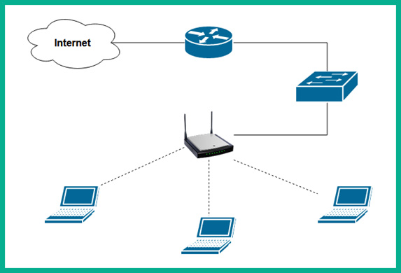
Figure 2.24 – WLAN network type
As shown in the preceding diagram, the laptop establishes a wireless connection to the wireless router. For the clients to access the resources on the wired network and the internet, the wireless router is connected to a network switch using a network cable. If wireless clients such as laptops are placed further away from the wireless router, the reception of the wireless signal by the client device will become weaker and the bandwidth will be affected.
Next, you will discover another network type that is commonly used within large educational institutions, such as universities.
Campus area network
In the world of academia, there are many universities around the world. Some universities have a single, large campus with many buildings containing classrooms, lecture halls, administrative offices, and so on, while other universities have multiple campuses at different geographic locations. For larger universities with many campuses, the network engineers within those academic institutions need to interconnect each campus to each other to ensure the users on each campus network can access and share resources. This type of network is commonly referred to as a campus area network (CAN).
The following diagram shows an example of a university with two campuses that are interconnected using a CAN:

Figure 2.25 – Campus area network
As shown in the preceding diagram, Site 1 and Site 2 are interconnected using a CAN network connection that is maintained by the university.
Next, you will learn about a special network type that is designed to support large storage servers.
Storage area network
Within large organizations and data centers, there are dedicated networks that are designed to support a large number of dedicated services that store data. Within each storage or file server, there are a lot of hardware-based redundancy technologies implemented such as a dual Network Interface Card (NIC) to support NIC Teaming, a technology that allows more than one NIC to be used to redundant network connections on a server. Another common technology within the file or storage servers is using Redundant Array of Independent Disks (RAID) to support data redundancy between multiple drives on a single server.
A storage area network (SAN) is a dedicated area within an organization’s network or data center that is used to physically implement multiple storages or file servers. The SAN is designed with both fault tolerance and redundancy in mind to ensure the network is always available. Additionally, the SAN needs networking devices such as switches and devices optimized for fiber channels, a technology that allows Ethernet over fiber optic cables. Using fiber optic cables ensures high bandwidth is supported within the SAN.
The following diagram shows an example of a SAN:

Figure 2.26 – Storage area network
As shown in the preceding diagram, each server has dual-homed connections to each fiber switch to support network redundancy. Redundancy is needed on the network so that if one networking device fails or a path is unavailable, the networking devices can automatically detect the failure on the network and re-route the network traffic using a backup or alternative path.
Software-defined wide area network
Within a software-defined network (SDN), a controller is implemented that acts as the brain of the network. In a traditional network, each networking device, such as a router or switch, has a brain that tells the device how to forward traffic. Therefore, each device has to make its own, independent decision whenever it has to forward a packet to a destination. Implementing SDN allows a centralized controller to be implemented on a network. Here, the controller becomes the central brain of all the network devices, removing the decision-making function of each networking device on the network.
A software-defined wide area network (SD-WAN) allows networking professionals to define their intent for a network such as a WAN and allow the software to configure the network to operate. Organizations commonly use traditional WAN technologies to interconnect their branch and remote offices to share resources. With SD-WAN, organizations can allow the software to automatically configure the WAN solution while continuously optimizing the connection between branches for improved performance.
The following diagram shows an example of an SDN controller and networking devices:

Figure 2.27 – SDN networking concepts
The idea of SDN allows networking professionals to easily manage the entire network as it grows by using the controller on the network. The controller can proactively monitor the network for any potential issues that may occur and take proactive actions to mitigate the issue. When working with SD-WAN or SDN, new networking devices can be configured to establish a connection to the SDN controller. Once a connection has been established, the SDN controller can automatically push configurations to each newly connected networking device.
Next, you will learn about a service provider technology for interconnecting multiple branch offices of an organization.
Multiprotocol label switching
Multiprotocol label switching (MPLS) is a service provider technology that allows organizations to interconnect their branch offices over a large geographic distance. Within the service provider’s network, a private and dedicated MPLS connection is established to interconnect an organization’s offices (remote sites). When working with MPLS, the organization (customer) can use various types of interfaces or connection methods to forward traffic to the service provider’s network. Simply put, the connection to the service provider’s network is interface-independent, allowing the organization (customer) to use a Metro Ethernet (MetroE), fiber optic, or even a Digital Subscriber Line (DSL) connection. Within the MPLS network, the ISP can logically create a bridge to interconnect all the branch offices of an organization (customer) quite easily without depending on a specific interface type or connection type.
Within an MPLS network, service providers can enhance the Quality of Service (QoS) that applies prioritization of various traffic types over others on a network. Additionally, service providers ensure the customers’ traffic remains private when using MPLS. When an organization sends packets into an MPLS network, each packet is tagged with an MPLS label by the Label Edge Router (LER) on the Provider Edge (PE) of the service provider’s network.
The following diagram shows an example of an MPLS network:

Figure 2.28 – MPLS network
As shown in the preceding diagram, two customers are using MPLS to interconnect their branch offices. When Customer A sends traffic into the MPLS network, it arrives at the LER, which is located at the PE of the service provider’s network. The LER inserts an MPLS label into each packet received from Customer A with a unique label before forwarding the packet to the Provider Routers. When a Provider Router receives a packet, it inspects the MPLS label to determine how to forward the packet to its destination without needing to open the contents of the packet to view the header information.
Next, you will learn about routing encapsulation technologies that are used to establish a secure connection between remote offices and the main office of an organization.
Multipoint generic routing encapsulation
The generic routing encapsulation (GRE) is a tunneling technology that allows an organization to establish a tunnel between one site (office) to another over the internet. When working with GRE tunnels, it allows network professionals to establish a point-to-point tunnel between two offices only. GRE works well when there’s a small number of branch offices for a single organization as each GRE tunnel per remote site (office) is only a unique IP network.
The following diagram shows an example of a GRE tunnel for a single organization:

Figure 2.29 – Traditional GRE tunnels
As shown in the preceding diagram, each branch office has a GRE tunnel to the main office router over the internet. Each GRE tunnel is responsible for encapsulating packets between each branch office to the main office. However, traditional GRE tunnels do not support scalability well as each tunnel is on its own IP network. Furthermore, if one of the branch offices wants to send a message to another branch office, the traffic is sent to the hub (main office router), which is then forwarded to the destination network, like in a traditional hub and spoke topology.
In multipoint generic routing encapsulation (mGRE), both the hub router and each branch office router can be configured to support dynamic mGRE. This method allows a branch router to automatically establish a GRE tunnel to another branch router if needed. Unlike the traditional GRE method of using a hub and spoke model, mGRE allows the routers within the mGRE network to automatically establish, maintain, and terminate mGRE tunnels between any routers within the network.
The following diagram shows an example of an mGRE network:

Figure 2.30 – mGRE tunnels
As shown in the following diagram, each branch router can establish an mGRE tunnel with another branch router, allowing branch offices to directly communicate and share resources without the need to use the traditional hub and spoke network topology.
Having completed this section, you have learned about the various network types and their characteristics. In the next section, you will explore the different service-related entry points to a customer network.
Identifying service-related entry points
A service-related entry point is simply the point where both a service provider and their customer’s network interconnect. Imagine contacting an ISP for residential internet service for your home. Usually, the customer, such as yourself, will already have a LAN with various types of networked devices such as computers, printers, and so on.
The demarcation point or demarc is the location where the service provider and the customer’s networks meet. If the ISP provides the customer with a modem, then the modem is the demarcation point on the network. The demarcation point also identifies the boundary that the ISP can provide support, such as troubleshooting issues, to ensure the internet service is working as expected.
The ISP will dispatch a crew to visit your location to implement their network infrastructure between the service provider network and your building or home. For customers opting for a fiber connection, the ISP crew will establish a connection between the Fiber Access Terminal (FAT) on the service provider network to the customer premise by using an optical drop cable. The FAT is simply an Optical Termination Box (OTB) that allows the ISP crew to easily manage multiple fiber connections to customers’ locations and to function as a termination point for the optical drop cable from the customer premises. The FAT allows the ISP to supply its customers with fiber-to-the-home (FTTH) services. Next, a fiber patch cable is used to connect the panel box installed on the customer’s premises to the fiber modem installed by the technology within their home. At this point, the customer can connect their LAN to the fiber modem to access the internet.
The service provider is responsible for the networking devices and technologies between the service provider’s network and the demarcation point. If no issues exist there, then the customer has the responsibility to troubleshoot their private network within their home or building.
The following diagram shows an example of a typical network between a customer location and the service provider network:

Figure 2.31 – Service provider network
As shown in the preceding diagram, the demarcation point can be identified as the modem that is installed within the customer’s location, such as their building or home. The service provider is responsible for everything that’s between the modem and the service provider’s network.
Another component that is commonly installed by the service provider on the customer’s building is a device known as a SmartJack. This is a special hardware-based component that functions as a Network Interface Unit (NIU) that provides feedback to a service provider such as an ISP. The SmartJack helps ISPs to determine whether there’s an issue that exists between the service provider’s network and the demarcation point at the customer’s end by providing a remote loopback.
Having completed this section, you have learned about service-related entry points on a network. Next, you will explore various types of provider connectivity methods.
Comparing provider links
Service providers such as ISPs provide their customers with various services such as WAN and internet solutions. Additionally, ISPs provide various methods to allow their customers to connect to the internet and WAN solutions. In this section, we will be covering a wide range of provider connectivity methods and their characteristics.
Satellite
Sometimes, an organization or residential customer may be geographically located within an area where there isn’t any fiber optic or copper lines installed in the community. Service providers can use satellite technologies to allow their customers to access the internet or interconnect remote branch offices to a WAN service.
The following diagram shows an example of using a satellite for network connectivity:

Figure 2.32 – A satellite link
As shown in the preceding diagram, there’s a satellite dish installed at the customer’s location that provides a connection to a satellite in orbit. The orbital satellite relays data between the customer Premise Equipment (CPE) to the service provider equipment, then through the service provider’s network to the internet.
Satellite technology is commonly implemented in areas that do not allow service providers to implement physical cabling to the customer location. When working with satellite technologies, the satellite dish needs a line of sight for communication. Therefore, if an object blocks the line of sight or there are bad weather conditions, the connection (signal) will be affected. Furthermore, this type of technology can provide high latency (response time), which may not be suitable for time-sensitive applications such as Voice over IP (VoIP) or Video over IP solutions.
Next, you will learn about another type of provider link that uses copper lines.
Digital Subscriber Line
The Digital Subscriber Line (DSL) is a service provider technology that is commonly used to provide internet services to residential/home users. This technology allows the ISP to install a modem in the subscriber’s (customer’s) building or home.
There are two types of DSL within the service provider industry, as follows:
- Symmetric DSL (SDSL): In SDSL, both the upload and download bandwidths are the same values. This solution is generally a very expensive option.
- Asymmetric DSL (ADSL): In ADSL, the upload and download are not the same. The download speed is generally much higher than the upload speed.
The DSL model is used to connect to the traditional telephone lines within the service provider network. These telephone lines are commonly referred to as the Public Switched Telephone Network (PSTN) lines and sometimes as the Plain Old Telephone Service (POTS) lines. The PSTN lines connect to a Digital Subscriber Line Access Multiplexer (DSLAM), which forwards the customer traffic from a region to the ISP network, then to the internet.
The following diagram shows a DSL network:

Figure 2.33 – DSL network
As shown in the preceding diagram, the user has a DSL model that splits the analog telephone signal and the digital signal to ensure the user can connect to the internet and use the telephone system without issues. Generally, DSL uses digital signals and requires a splitter, a hardware-based component to separate the telephone signal from the internet signal. One of the disadvantages of using a DSL is it works up to an average of 5.5 km in distance. Therefore, the further away a subscriber (customer) is from the DSLAM, the service quality will be impacted. This is commonly referred to as attenuation – that is, the loss of signal over distance within these lines.
Important note
A modem is used to convert an analog signal into a digital signal and vice versa. The terminology used to describe this conversion is modulation and demodulation.
Next, you will discover how service providers distribute internet services through their cable network to customers.
Cable
Many cable TV companies provide internet service to their customers over their existing cable networks. Cable TV and internet services are commonly distributed to home/residential customers compared to business customers using fiber optic. Service providers install a cable modem in their customers’ locations, such as in their homes, which allows the cable modem to connect to the service provider’s Cable Model Termination System (CMTS) via coaxial cables.
The following diagram shows a simple overview of the CMTS network:
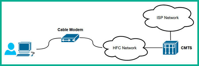
Figure 2.34 – CMTS model
As shown in the preceding diagram, the ISP’s backbone network is connected to the CMTS network infrastructure. The Hybrid Fiber-Coaxial (HFC) infrastructure is a telecommunication provider’s hybrid network that supports both fiber and coaxial infrastructure. The HFC network is used to connect all the cable modems from the customer location to the CMTS, then to the internet via the service provider’s network.
When using a cable, it uses Data over Cable Service Interface Specification (DOCSIS), which is an international telecommunication standard that supports 10 Gbps download speeds and 1 Gbps upload speeds. Unfortunately, the total bandwidth is shared as more customers use the cable network. As a result, as more customers use the internet at the same time, each customer will notice their internet speed is reduced.
Next, you will learn how businesses used dedicated lines to ensure their network bandwidth was guaranteed.
Leased line
A leased line allows a service provider to interconnect an organization’s branch offices together. When using leased lines, the network bandwidth on the leased line is dedicated to the organization (customer) and always available, regardless of whether the customer uses it. Leased lines are expensive since they are dedicated to allocating network bandwidth to the paying customer to interconnect their remote offices.
The following diagram shows an example of an organization using leased lines to interconnect their main office with their branch offices over a service provider’s network:

Figure 2.35 – Leased lines
The following are the major benefits of using leased lines for connectivity:
- Provides a connection with dedicated bandwidth
- This dedicated connection is provided between the customer and the service provider network
However, since leased lines provide a dedicated and not shared connection, this type of connection is usually more costly as the bandwidth is statically allocated to the customer.
Next, you will learn about the characteristics of metro optical links.
Metro optical
Metro optical is a type of provider link that allows an organization to access the service provider’s network for internet access and even WAN solutions. The metro optical network consists of fiber optic cables that are used to provide very high-speed network connectivity between the customer and the service provider’s network.
This type of network usually costs less than typical Synchronous Optical Networking (SONET) and Synchronous Digital Hierarchy (SDH) and works with Ethernet technologies. SONET is used on fiber optic networks, which allows a large quantity of data to be transported over great distances. On the other hand, SDH is simply described as a multiplex technology and a variant of SONET.
Having completed this section, you have discovered and learned about various provider links that allow organizations to access service providers’ networks.
Summary
In this chapter, you learned about the various characteristics of different network topologies and how they are used to interconnect the nodes of an organization. You saw that within the networking industry, there are many network types and each has its unique features. Lastly, you learned about the various service provider technologies that are used to interconnect organizations over large geographic distances.
I hope this chapter has been informative for you and is helpful in your journey toward learning networking and becoming a network professional. In the next chapter, Chapter 3, Ethernet Technology and Virtualization, you will discover the various Ethernet standards, cabling types and connectors, and virtualization.
Questions
The following is a short list of review questions to help reinforce your learning and help you identify areas that may require some improvement:
- Which network type is commonly used to extend a LAN over a great distance?
A. Hub and spoke
B. WAN
C. Hybrid
D. DSL
- Which of the following network technologies has very high latency when interconnecting remote offices?
A. Satellite
B. Cable
C. WAN
D. CAN
- Which of the following service provider technologies provides high-speed internet access over traditional telephone lines?
A. Metro optical
B. Cable
C. DSL
D. MPLS
- Which of the following service provider technologies labels the incoming packets from a customer’s network while improving faster forwarding of the packets through the service provider’s network?
A. ADSL
B. Cable
C. mGRE
D. MPLS
- If two mobile devices establish a Bluetooth connection, which type of network is created?
A. CAN
B. Peer-to-peer
C. PAN
D. MAN
- Which of the following network types allows network professionals to automate the configuration of WAN solutions?
A. mGRE
B. SD-WAN
C. MPLS
D. SDSL
- Which of the following network topologies allows only one end device to communicate at a time?
A. Star
B. Ring
C. Peer-to-peer
D. MAN
- Which of the following is an operating frequency for wireless networks?
A. 5.6 GHz
B. 5.4 GHz
C. 2.5 GHz
D. 2.4 GHz
- The routers on the edge of the service provider MPLS network are known as what?
A. Provider routers
B. CPE
C. LER
D. None of the above
- Which of the following provider links uses coaxial to distribute internet and TV service to customers?
A. Leased line
B. DSL
C. Cable
D. Satellite
Further reading
To learn more about the topics that were covered in this chapter, check out the following links:
- Networking Basics: https://www.cisco.com/c/en/us/solutions/small-business/resource-center/networking/networking-basics.html
- What is Computer Networking?: https://www.cisco.com/c/en/us/solutions/enterprise-networks/what-is-computer-networking.html
- What is Network Topology?: https://www.cisco.com/c/en/us/solutions/automation/network-topology.html