
17
Network Troubleshooting
As an aspiring network professional, designing and implementing networks is an amazing experience. However, understanding how to identify, troubleshoot, and resolve issues makes a better network professional within the industry. While network implementation and operations are important, network troubleshooting is equally important. Being excellent at network troubleshooting allows a network professional to validate their understanding of the technology to determine the true probable cause of issues by using their knowledge from learning about networking, their wisdom, and skills from experiences to resolve the issues and implement preventative controls. While troubleshooting is a problem-solving skill within the field of networking, it takes some time to develop and improve upon each time a new issue occurs.
In this chapter, you will explore network troubleshooting methodology and approaches used by network professionals within the industry to identify and resolve network-related issues using a systematic and efficient technique. You will also learn how to identify various types of wired and wireless connectivity issues, their probable causes, and how to resolve them. Additionally, you will discover common hardware- and software-based troubleshooting tools to assist you as a network professional, as seen in the following list:
- Network troubleshooting methodology
- Cable connectivity issues
- Wireless connectivity issues
- Common network issues
- Hardware-based troubleshooting tools
- Software-based troubleshooting tools
Let’s dive in!
Network troubleshooting methodology
Proper network troubleshooting follows a systematic approach. Rather than guessing solutions to problems based on unclear information and random theories, network professionals who follow a proper troubleshooting methodology perform a specific, organized process that helps them to be more efficient in their problem-solving operations.
The following is a step-by-step network troubleshooting methodology:
- Identify the problem.
- Establish a theory of probable cause.
- Test the theory to determine the cause.
- Establish a plan of action to resolve the problem and identify potential effects.
- Implement the solution or escalate as necessary.
- Verify full system functionality and, if applicable, implement preventive measures.
- Document findings, actions, outcomes, and lessons learned.
Let’s look at each step in detail:
- Identify the problem: The first step in troubleshooting any network issue is to identify the problem that has arisen properly. In many instances, network professionals are presented with symptoms of the problem through reports from other users, automated reports by monitoring software, or their own observations. Often, these symptoms do not provide all of the information on the issue. It is, therefore, essential for the network professional to gather as much data as possible regarding the problem.
- Establish a theory of probable cause: By gathering additional data, network professionals are able to understand the root cause of the issue better and determine whether a single issue exists on the network or whether the symptoms relate to multiple problems that need to be segmented and worked on individually. Additional data can be gathered from devices involved in the issue, log files in log management software, and other reports stored locally on the device or remote management software. Data may also be gathered by questioning users involved in the issue, attempting to duplicate the issue (while observing the network more closely), or assessing what changes have been implemented on the network recently.
- Test the theory to determine the cause: Once sufficient data has been gathered in relation to the problem that has manifested itself on the network, network professionals then utilize the data they have gathered to establish a theory of probable cause or, in other words, to make an educated assumption about the cause of the issue. In establishing this theory, it is important not to overlook any of the obvious possible causes of the issue. Many issues that may appear complex at first glance may be caused by simple occurrences on the network. To formulate their explanation of the cause of the issue, network professionals may follow several approaches, including segmenting the problem into multiple smaller problems or working through each layer of the Open Systems Interconnection (OSI) model, either from top to bottom or vice versa. These approaches may even be combined to form a more cohesive explanation of the cause.
Once a proper theory has been established, network professionals must test their formulated theory concerning the cause of the issue. This test will illustrate whether the theory was correct. If the theory is correct, the network professional can continue with the troubleshooting process to determine an appropriate resolution to the issue. If the theory is shown to be incorrect, then return to the previous step to establish an alternative theory to test. At this stage, the network professional may also request help from other staff members or escalate the issue if desired.
- Establish a plan of action to resolve the problem and identify potential effects: Once a theory regarding the cause of the issue is proven to be correct, the network professional must move on to establishing a plan of action to resolve the issue. At this stage, sufficient data has likely been gathered to formulate a proper solution to the problem. However, the network professional may still need to consult with other staff members to establish a plan for the proper resolution of the issue. In many cases, the resolution process can affect business processes and, as such, the network professional must work alongside team members to identify potential repercussions of the resolution plan and to both test the plan and schedule an appropriate time to implement it so that it impacts business processes as little as possible.
- Implement the solution or escalate as necessary: After establishing and verifying the plan of action, the network professional can finally implement the formulated solution. Depending on the anticipated impact on other processes, this plan of action may have to be implemented during off-periods in an approved maintenance window. It may also be necessary to request the aid of other personnel in the organization or to escalate the solution to other staff members for implementation. For instance, if the plan involves a significant number of devices under the jurisdiction of another staff member, it may be appropriate to escalate the plan to that member.
- Verify full system functionality and, if applicable, implement preventive measures: After implementing the plan of action, it is necessary to perform testing on all affected systems to verify full system functionality. This step ensures that no other business processes are unduly affected by the solution. Depending on the circumstance, it may also be necessary to implement preventative measures to prevent the issue from recurring. For instance, if the issue that occurred involved power outages due to loosened power cables, it would be appropriate to secure the cables to both the outlet and the Power Supply Unit (PSU) to ensure that the cable does not come undone again.
- Document findings, actions, outcomes, and lessons learned: Lastly, it is important to keep a record of the entire process. Although the issue and its resolution may seem impossible to forget at the time of the incident, network professionals often forget the issue entirely within the space of a few months. Through proper documenting of the issue, from the initial report to the final testing of the implemented solution, network professionals can save themselves a lot of stress by being able to simply reference their documentation when similar issues arise in the future.
Having completed this section, you have learned a common network troubleshooting methodology that’s used by many network professionals within the industry. Next, you will deep dive into exploring common issues on a wired network.
Cable connectivity issues
In this section, we will address some of the most common connectivity and performance issues that transpire on wired networks. As most of these issues exist at layer 1 and layer 2 of the OSI model, higher-layer protocols will frequently exhibit issues when these problems exist since these higher-layer protocols depend on the services offered by the lower layers. It is therefore recommended that network professionals become familiar with the symptoms of these issues and perform a bottom-to-top troubleshooting methodology when they suspect that these problems are present.
Link lights/status indicators
Most equipment, such as switches, routers, and firewalls, includes lights on each physical interface where cables can be plugged into the equipment, which helps network professionals to diagnose physical layer issues on those links. Lighting schemes differ between different equipment vendors, but a lack of lights on an interface generally corresponds to no signal being received across the link for that interface. Network professionals can therefore use the presence or absence of link lights on the interfaces to determine whether links are functioning properly or whether troubleshooting is required.
Damaged cables and connectors
The first step in troubleshooting a physical layer issue should always be to search for bends or breaks in the cabling or connectors (including in the pins of the connectors). These issues can be diagnosed through physical inspection or by utilizing a multimeter or cable tester to check continuity across cables and pins (to search for open circuits or shorts between circuits). These issues are usually remedied by simply replacing the damaged component in the link or by replacing the entire cable if deemed necessary.
Incorrect TX/RX alignment
Rather than being linked to damaged cables or connectors, some issues can be traced to misaligned pins or connectors on equipment, resulting in the TX (transmitting) and RX (receiving) sides of both ends not corresponding correctly. On copper cables, this may be due to wires being crimped improperly, while on fiber cables, this may be due to the incorrect placement of each duplex connector. For copper cables, therefore, the remedy is usually to re-crimp the cables with the proper pin-out or utilize ports with a Medium-Dependent Interface (MDIX) if required, while fiber cables simply require a reversal of the connectors at one end of the link.
The following diagram illustrates this issue of incorrect TX/RX alignment:

Figure 17.1 – TX/RX transmission issue
As shown in the preceding diagram, both switches are unable to send or receive messages to the other due to incorrect TX and RX alignments.
Attenuation
Attenuation refers to the reduction in amplitude of a signal as it propagates through a system due to the losses present in the system. Attenuation may be caused by a number of factors, including resistance in copper cables, absorption in fiber cables, and reflection in fiber connectors. Attenuation is the physical phenomenon that limits the maximum length of a link since equipment requires a particular minimum threshold of signal power to communicate across the link. In diagnosing attenuation issues, it is important to observe whether link lights are present on equipment, note the maximum link length for the cables/transceivers used in the link, and utilize tools such as light meters to measure the received signal strength at both ends of the cable.
Crosstalk and Electro-Magnetic Interference (EMI)
Crosstalk refers to the phenomenon whereby electrical signals transmitted in one circuit induce an undesirable electrical signal in another. In the field of networking, crosstalk manifests itself most frequently in twisted-pair copper cabling. A number of techniques have already been employed to reduce crosstalk in these cables, including twisting the cables and wrapping the cables in shielding, but crosstalk may still occur due to cables being untwisted at the ends. In many newer category cables, such as Cat 7, it is necessary to maintain the twists straight up to the connector end.
While crosstalk deals with interference generated from within the cable, EMI deals with interference sourced from outside the cable, which may be generated by a number of components, including microwave ovens and generators. Crosstalk and EMI problems may manifest themselves as cables unable to support the speeds they should or as a high number of errors across the cables. These problems may be remedied by techniques such as ensuring that twists remain right up to the connector, using cables with more shielding, or moving the copper cables away from significant sources of interference.
Bad ports/transceivers
There may also be cases where physical interfaces/ports on equipment may be damaged or configured incorrectly. In the case of damaged ports, the link can be established properly by simply moving the cable to another port on the device. Bad ports are usually not easily repaired by network professionals and are commonly simply marked as damaged. In certain cases, the entire device may be returned to the manufacturer for repair. In some cases, ports may appear non-operational if they are not configured with the same speed and duplex settings on both ends.
Ports must be configured with these settings matching on both ends of the link for the link to be established. Additionally, links may not be established due to the transceivers used at both ends. These transceivers may be incorrect for the type of link being established. For instance, a transceiver designed for Multi-Mode Fiber (MMF) may be inserted into a port while the link uses a Single-Mode Fiber (SMF) cable, the transceiver may be manufactured for a different device (many devices require transceivers manufactured from the same vendor), or the transceiver may simply be damaged. These situations can be remedied by sourcing the correct type of transceiver from the correct vendor, ensuring that the same type of transceiver is used on both ends of the link, and switching the transceiver to a known working module.
VLAN mismatch
While troubleshooting connectivity issues on switches that support and employ VLAN tagging, it is important to check how the ports on both ends of a link are configured. VLANs segment broadcast domains and are (usually) also implemented with different networks assigned to each VLAN. Therefore, it is important to check that the port undergoing troubleshooting is assigned to the correct VLAN ID. It is also important to ensure that the VLAN being tested has been created in all relevant switches in the network, as switches do not usually pass VLANs that have not been created on them.
Sub-optimal performance
Even if connectivity has been established across a link, there may be cases where performance across the link is sub-optimal. For instance, network professionals may notice high amounts of latency, such as a delay between transmitting and receiving packets across a link or jitter – the variation in latency across a link. This may be caused by factors such as the length of the cable since the signals used to transmit packets across a link takes some time to travel or interference across the link.
Additionally, network professionals may notice that links are not performing at their rated speeds due to the aforementioned factors or due to incorrect cable types being used. For example, a Cat 6 cable may not be able to deliver 10 Gbps across the full 100 m, as a Cat 6a cable might be able to. Due to these links operating at lower speeds, bottlenecks may be created in the network.
If a transmission is being performed across several links, the transmission would only be able to run at the speed of the slowest link in the chain. Many of these issues can be remedied by replacing copper cables with fiber cables. Since light pulses travel faster than electrical signals, latency in fiber cables is usually lower than in copper cables. Fiber cables also do not suffer from EMI or crosstalk. Additionally, fiber cables also have maximum link lengths that are much higher than copper cables, allowing speeds to be maintained across longer runs of cables.
The following diagram illustrates a common bottleneck scenario:

Figure 17.2 – Sub-optimal issue
In this section, we have covered many of the issues commonly seen on wired networks in the hope that you can now troubleshoot these issues much more quickly. In the following section, you will discover prevalent issues often found on wireless networks.
Wireless connectivity issues
Wireless networks are becoming more and more ubiquitous around the world as they free us from many of the technical difficulties of wired networks. However, they also introduce a number of complications that must be considered. In this section, we will explore some of the most common issues that technicians face in wireless networks.
Physical layer issues
Wireless signals face even more obstructions than signals in wired media, as these wireless signals propagate in unguided media. Radio frequency (RF) signals between Access Points and client devices often have to propagate through various objects and materials, including concrete walls, glass, and other electronic items. While propagating through these materials, these signals may undergo phenomena, such as reflection, where the signals bounce off certain surfaces such as metallic objects; refraction, where the signals bend due to traveling through two dissimilar media; and absorption, where the signals lose a lot of their power while propagating through different materials.
As a result of this, latency and jitter across wireless networks are often significantly higher than in wired networks since RF signals may take a longer time to travel across wireless media, and each RF signal can take a variety of different paths, each with its own corresponding delay. Network professionals must, therefore, properly assess the environment in which their wireless networks will be used and try to minimize the number of obstructions present by positioning their Access Points appropriately.
The following diagram illustrates some of the physical issues on a wireless network:

Figure 17.3 – Physical obstructions
As shown in the preceding diagram, the walls are absorbing the radio frequency that is emitted from the Access Point. As a result, the laptop computer is experiencing poor reception of the wireless signal. Hence, the user will experience poor network performance.
Antenna issues
To mitigate some of these physical layer issues, network professionals should properly plan their antenna choice and placement in the network. Omnidirectional antennas are the most popular antennas supplied with Access Points, but they may not be the most appropriate for all situations. Omnidirectional antennas radiate power approximately uniformly in all directions and are, therefore, well-suited to environments where wireless coverage needs to extend to fill an entire room and where the Access Points can be placed in the center of the room.
However, there may be other environments that require the use of directional antennas, which radiate power in one direction only. In these environments, antenna placement becomes even more critical, as technicians must ensure that the signal is radiated in the proper direction.
Signal power issues
Many wireless network issues are caused by clients simply not receiving sufficient Effective Isotropic Radiated Power (EIRP), better referred to as power settings or signal power for proper operation. Wireless signals are attenuated by a number of factors, including the reflection, refraction, and absorption phenomena, as discussed previously. Additionally, wireless signals lose power as they propagate through physical media (air in most environments). Therefore, even in the absence of any objects to cause additional losses, signal power is reduced as the distance to the transmitter is increased, resulting in a maximum distance at which a client device can communicate with an Access Point. To increase this maximum distance, network professionals may increase the power levels on their Access Points. However, this does not necessarily increase the range of the network unless the client power levels are also increased.
Interference
In addition to signal power levels, network professionals must also consider the levels of interference in their wireless networks. Wireless networks operate using particular frequency bands. For instance, the IEEE 802.11n protocol commonly operates on 20 MHz channels, meaning that even though 11–14 channels are available for use, depending on the region in which the devices are operating, these channels cannot all be used as channel overlaps will occur.
For this reason, network professionals must plan their wireless networks properly, ensuring that adjacent networks utilize channels with proper spacing to avoid overlaps and interference, thereby ensuring that clients meet or exceed their minimum threshold Signal-to-Noise Ratio (SNR), the ratio of the wireless signal power to the power of external noise and interference signals required for optimal performance.
The following diagram illustrates the non-overlapping channels used in many IEEE 802.11n networks:

Figure 17.4 – Non-overlapping channels
As shown in the preceding diagram, channels 1, 6, and 11 are non-overlapping channels on IEEE 802.11 wireless networks, which use the 2.4 GHz frequency. Channel 14 is only permitted for usage in Japan.
Client configuration issues
In many instances, network professionals may discover that their wireless networks are configured correctly, but a single client is not configured properly for the network they are trying to access. Some common client issues include the client device not being able to support the correct frequency; for example, the client device may only support 2.4 GHz networks, while the nearest Access Point to it only supports 5 GHz. Another common issue is the client device is connected to the wrong Service Set Identifier (SSID); hence it’s trying to access the incorrect network, or the client device is configured with incorrect passphrases or wireless security standards, resulting in it not being able to authenticate and join the wireless network. These issues must be treated on a case-by-case basis, requiring the network professional to compare the configuration on problematic clients with the desired configuration and then reconfigure the devices as required.
In this section, we’ve covered many common issues experienced while administering wireless networks. In addition to these wireless-specific issues, network professionals frequently experience several network service issues that impact clients on their networks. In the following section, we will describe some of these common issues.
Common network issues
Many issues network professionals encounter while troubleshooting networks are limited to particular client devices. In these cases, network professionals notice that all of the other clients on the network are operating correctly while the client in question exhibits issues. Here, network professionals should examine the network configuration on the client machine itself, paying particular attention to the possibility of the following:
- IP address duplication: In many networks with poor documentation practices, IP addresses may be reused on multiple clients, resulting in duplicate IPs on the network and poor/non-existent connectivity for the clients. For this reason, many professionals will ping the IP address they intend to use before configuring the IP address on a machine to check whether any other hosts are utilizing the intended address. However, many firewalls filter the Internet Control Message Protocol (ICMP) messages used by the ping tool, resulting in the network professional not receiving a response and reusing the IP address. This issue, therefore, reinforces the need for proper documentation.
- MAC address duplication: Although Media Access Control (MAC) addresses are not usually explicitly configured on host machines in the same way that IP addresses are, specialized software exists that allows hosts to utilize MAC addresses other than those embedded in their Network Interface Card (NIC). Therefore, rogue agents on the network may spoof MAC addresses of machines on the network for nefarious purposes, preventing communication to the original host machine. Network professionals should be aware of this possibility and actively search the network for rogue agents that might be spoofing their valid MACs and implementing preventative measures such as layer 2 security controls.
- Incorrect gateway and subnet mask: IP addresses only form one part of a client’s layer 3 configuration. The subnet mask and gateway form another critical part of the configuration, telling the host the size of the network that it is a part of, and letting it know which device it should communicate with to transport packets out of its own network. Therefore, network professionals must verify these configuration parameters and ensure that they match the network that the client is part of.
- Incorrect DNS/NTP servers: Client machines are usually configured to communicate with several servers that provide particular services that the client needs. Two of the most important services are name resolution services provided by Domain Name System (DNS) servers and time synchronization services provided by Network Time Protocol (NTP) servers. Network professionals must verify that both these servers are configured correctly on the client machines. DNS services can be verified by using the nslookup or dig tools. For time synchronization services, network professionals should verify the correct time zone is set on the client and that the NTP server is responding.
In addition to these client configuration issues, some networks may suffer from Dynamic Host Configuration Protocol (DHCP)-related issues. These issues may include the following:
- Exhausted DHCP scope: Network professionals may notice new clients connecting to the network are not being assigned addresses from the DHCP pool. In some of these cases, it may be that the pool is simply exhausted on the DHCP server, and there are no more addresses to lease to new clients. In these cases, the network professional may consider expanding the pool, adding additional pools, or reducing the lease time to ensure that addresses are available for use more quickly.
- Expired IP address: In certain situations, host machines may not be able to communicate with DHCP servers to renew their IP address leases. In these cases, the host’s address may expire, and the host will be forced to request a new address. To prevent these situations, reservations may be created on the DHCP server.
- Rogue DHCP server: In some instances, network professionals may notice DHCP messages from servers other than those they configured. In these cases, it may be necessary to locate these rogue DHCP servers and disconnect the machines manually or explicitly configure particular ports on their networks to allow DHCP servers and deny server messages from all other ports.
In some networks, misconfigured security policies may prevent proper network operation. Some of the most common security problems include the following:
- Untrusted digital certificates: Web browsers may complain about untrusted digital certificates for several reasons. In some cases, the certificate may be signed by a trusted Certificate Authority (CA) but may be rejected by the browser due to a number of issues, such as missing intermediary certificates or misconfigured or expired certificates. In other cases, the server may be using a self-signed certificate that has not been imported into the client’s certificate store. Most web browsers provide the network professional with some information about the problematic certificate, which helps in the troubleshooting process.
- Incorrect network or host firewall settings: In some networks, firewalls at particular points may block valid traffic from reaching their intended destination. The firewalls (either host-based or network-based) may be configured with Access Control Lists (ACLs) that drop traffic to valid destination addresses or ports and require the network professional to trace the traffic through the entire path in the network and determine which node along the path drops the traffic. The network professional should always be aware of implicit denying rules that may exist in ACLs that silently discard traffic on the network.
Lastly, some issues may be simply due to hardware or software failures. Many system processes and hardware devices often become stuck due to problematic software functions or components, requiring the network professional to restart the particular software process or hardware device. In some instances, these devices may need to be upgraded or replaced if the network professional notices that they are becoming stuck and impacting services too frequently.
Having completed this section, you have discovered common network issues that can create a problem on the network. In the next section, you will learn how to use hardware-based tools to resolve physical issues within your network.
Hardware-based troubleshooting tools
Let’s first investigate some of the common hardware devices used to troubleshoot and repair both copper-based and fiber-based networks:
- Crimper: A crimper is a tool used to attach copper cables to connectors. In modern networks, this is most often used to attach a twisted-pair copper cable to RJ45 connectors, but crimpers also exist for other types of copper cables. The main purpose of a crimper is to press electrical contacts down into the individual copper cables, thereby establishing electrical connectivity between the cables and the connectors. Additionally, they press the plastic hammer down onto the outer sheath of the cable, thereby fixing the connector to the cable. Crimpers usually contain parts to peel the outer sheath and trim the length of the individual copper wires.
The following photo shows a crimping tool:

Figure 17.5 – Network crimper/crimping tool
- Cable tester: After copper cables are crimped on both ends, cable testers are usually used to ensure that proper electrical connectivity is established and that electrical signals can traverse the cable properly. Most cable testers simply send a test signal from one end of the tester and verify that the signal is received on all pairs at the other end of the cable. More advanced (and more expensive) cable testers, however, can also measure and display the physical properties of the cable under test.
The following photo shows a cable tester tool:
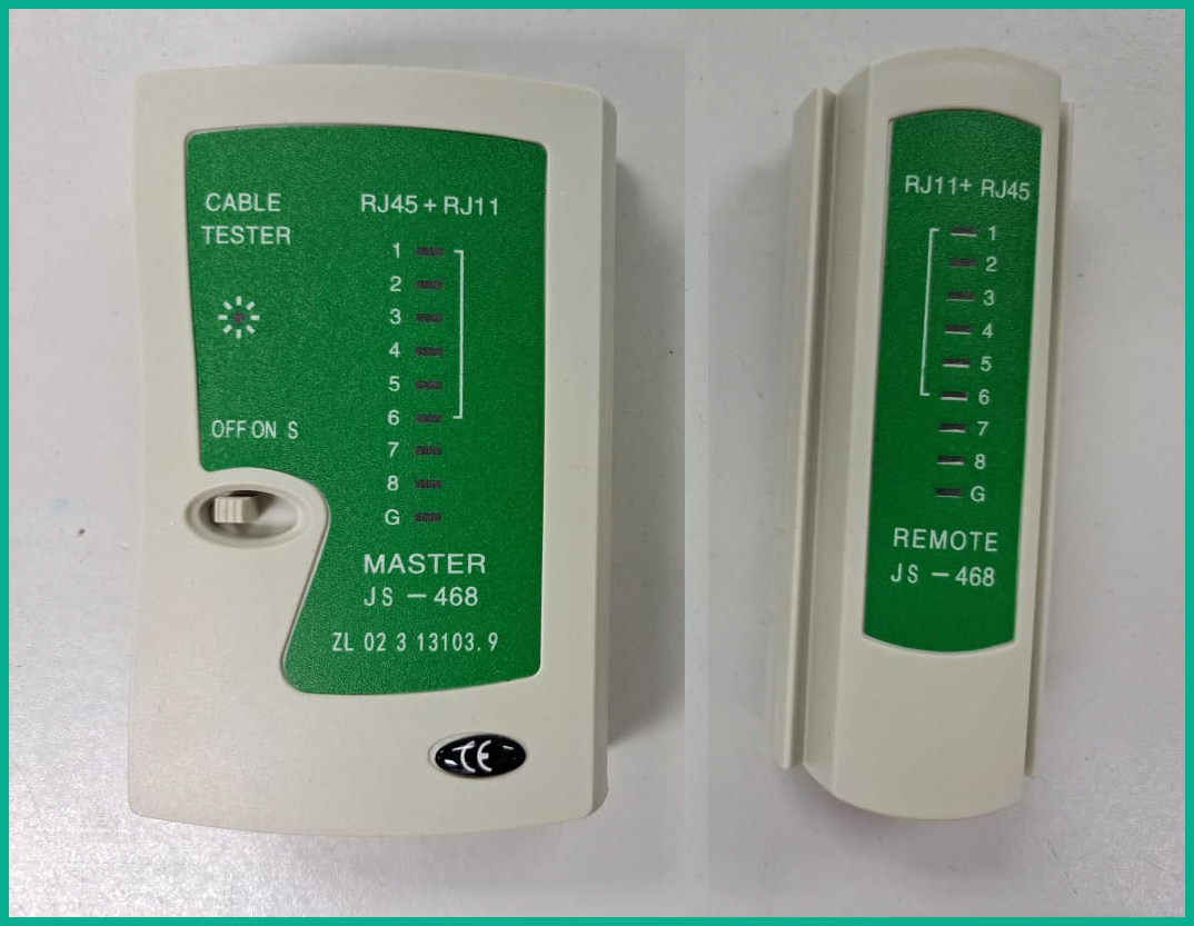
Figure 17.6 – Cable tester
- Punchdown tool: Rather than crimping the ends of the copper cable, the ends may be attached to 66 or 110 blocks. Punchdown tools are used to push individual cables from twisted-pair cables into their slots on the blocks and to cut off excess wiring at the end of the slots.
The following photo shows an example of a punchdown tool:

Figure 17.7 – Punchdown tool
- Tone and probe tool: A tone and probe tool is a device used to help network professionals to trace copper cables. The tone generator is attached to the start of the cable, and the probe (which generates a loud sound once it is held close to the cable under test) is run along the cable, allowing the network professional to easily follow the cable in dense wiring closets or racks, where it may be difficult to trace the cable visually.
- Loopback adapter: A physical loopback adapter is a device attached to equipment to feed a transmitted (TX) signal back into the receiving (RX) interface of the equipment. These adapters may be created for copper interfaces/cables by connecting the TX and RX cables or for fiber cables by connecting the TX and RX connectors or cables in duplex fiber. Loopback adapters are useful for diagnosing physical layer issues. For instance, a loopback adapter may be used at the end of a Wide Area Network (WAN) circuit to demonstrate that the cables for the WAN circuit are operating correctly.
- Multimeter: A multimeter may be used to test several parameters on copper cables. Multimeters can be used to test end-to-end continuity in cables, to check whether the cable is damaged, or to match cable ends as part of cable tracing work. They can also be used to test voltages in circuits such as Power over Ethernet (PoE) circuits and Power Distribution Unit (PDU) outlets.
The following photo shows a multimeter tool:
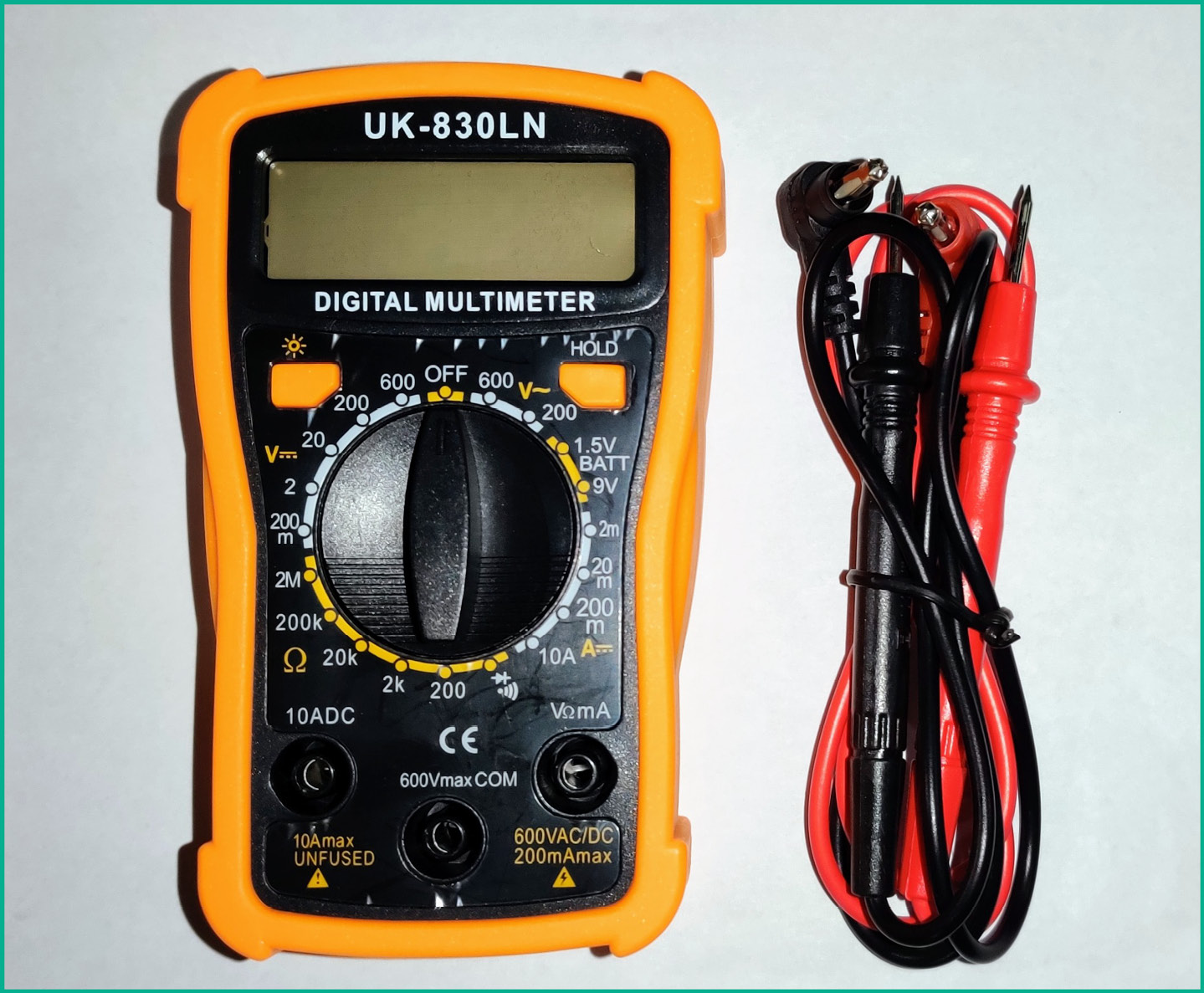
Figure 17.8 – Multimeter
Several other tools are commonly used in diagnosing optical networking issues. One such tool is an Optical Time Domain Reflectometer (OTDR). OTDRs inject a series of light pulses into fiber cables and record the scattered or reflected pulses they receive in return. Based on these received pulses, they can characterize fiber cables. OTDRs are commonly used to document fiber cables and to estimate points at which fiber cables are damaged, allowing fiber repair teams to greatly increase their efficiency in repairing damaged cables. OTDRs usually require operators to select the wavelength of the test pulse and display attenuation characteristics of the fiber according to the selected wavelength.
Another popular tool used for troubleshooting optical networks is a light meter or optical power meter. These tools also require operators to select their desired wavelength, allowing them to measure the optical power received on a fiber. These tools are essential in optical networks since equipment in these networks has particular minimum optical signal strengths, below which they cannot establish links. Light meters allow network professionals to measure optical signal strengths and determine whether the signal meets the minimum threshold for the equipment. Optical signal strength is usually referenced in decibel-milliwatts (dBm).
Lastly, network professionals often require the use of spectrum analyzers, which are used to examine radio frequency signals in the frequency domain, displaying the amplitude (strength) of signals for their frequency. These analyzers are commonly used to test electrical signals but may also be used to test other types of signals through appropriate transducers. Spectrum analyzers may be used to investigate interference or signal strength in a wireless network, the bandwidth of a particular signal across a wire, or the effectiveness of RF shielding in a particular cable.
In addition to these hardware tools, network professionals also commonly use a wide range of software tools in their troubleshooting methodology. In the next section, you will examine some of these software tools.
Software-based tools and commands
In this section, we will discuss some of the most common software tools and commands that technicians use to gather data within their networks.
Packet sniffer
A packet sniffer is a program used to capture packets traversing a network. TCPdump is a command-line packet sniffer, while other packet sniffers may have a graphical user interface, such as Wireshark. A packet sniffer is commonly combined with a protocol analyzer so that network professionals can capture and analyze traffic using a single piece of software. Under normal network configurations, packet sniffers can only capture unicast traffic directed at the host machine, multicast, and broadcast traffic on the network.
The following screenshot shows TCPdump capturing live packets on a network:

Figure 17.9 – A TCPdump packet capture
Therefore, network professionals usually configure monitoring ports on switches or utilize hubs to repeat traffic from other sources to their monitoring hosts. Packet sniffers and protocol analyzers can be used to perform in-depth investigations into networks, allowing network professionals to view the protocols and payloads involved in conversations between host machines. When capturing packets using a packet sniffer application such as TCPdump or Wireshark, it’s recommended to set the network interface card in promiscuous mode.
The following screenshot shows that the Wi-Fi 4 adapter is set to capture network traffic using promiscuous mode on Wireshark:

Figure 17.10 – Promiscuous mode
Promiscuous mode allows the network adapter to pass/process all network packets it receives, allowing a packet sniffer application to process each packet and display the information found within the packets.
Port scanner
A port scanner is a program used to identify open Transport layer service ports such as Transmission Control Protocol (TCP) and User Datagram Protocol (UDP) service ports on a machine. Port scanners are useful for assessing which services are running on a host machine since many ports are associated with specific services and application layer protocols. By utilizing port scanners, network professionals can assess the attack surface on their host machines and ensure that only necessary ports are left open.
A Network Mapper (Nmap) tool is used for scanning hosts or networks and identifying available hosts, running services, open ports, operating systems, and a variety of other information about the target system or network. This tool is commonly used for security audits and network documentation, aiding users in discovering additional information about their networks.
The following screenshot shows the output of Nmap, a common port scanner:
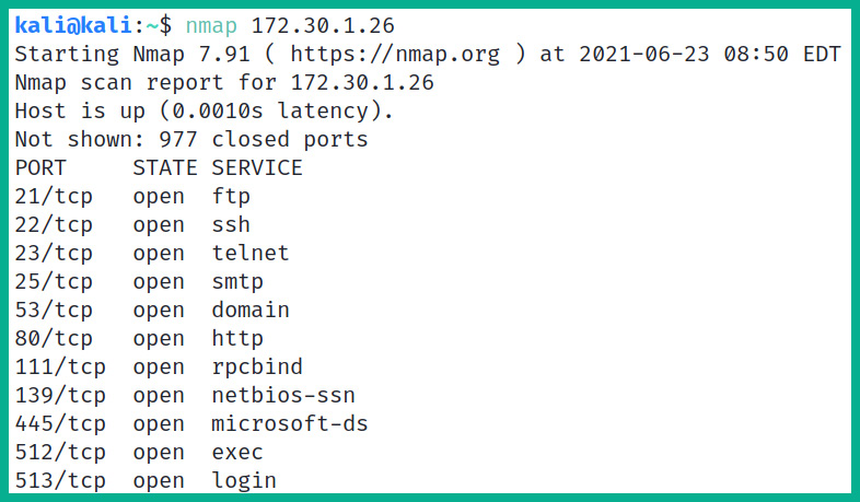
Figure 17.11 – Nmap results
Wi-Fi analyzer
A Wi-Fi analyzer is an application that scans wireless frequency ranges used by Wi-Fi devices, displaying information such as SSIDs, channels, Wi-Fi modes, and SNR from different Access Points within the range of the host machine. These analyzers are an important part of wireless network planning, arming network professionals with the knowledge required for tasks such as avoiding interference and scanning for rogue APs in the vicinity.
The following snippet shows the output of a Wi-Fi analyzer application on a laptop computer:

Figure 17.12 – A Wi-Fi analyzer application
As shown in the preceding screenshot, the application helps network professionals determine the channel being used by your current wireless network and those around you. Additionally, you can determine the Received Signal Strength Indication (RSSI), better referred to as the signal strength being received on your device.
Bandwidth speed tester
A bandwidth speed tester is an application used for testing the achievable throughput (speed) on a link. Speed tests are essential to ensure that links are performing as expected, and are an important part of ensuring that a Service-Level Agreement (SLA) is being met by the service provider. In running these speed tests, it is important to note the server used to perform the test, as many factors can affect the results, including the latency to the speed test server and the utilization of the link and server used for testing.
The following are common online speed test websites:
- Speedtest by Ookla – https://www.speedtest.net/
- Fast – https://fast.com/
Tip
The iPerf application allows network professionals to set up an iPerf server and client over a network and test the throughput between two systems to determine the bandwidth on an internal network or between branch offices. To learn about iPerf, please visit https://iperf.fr/.
Command-line tools
In addition to these applications, network professionals commonly utilize a number of command-line programs. These tools are called by entering their names in a command line or terminal window, along with any necessary options for the tool.
Address Resolution Protocol
Address Resolution Protocol (ARP) allows a host to resolve an IP address to a MAC address over a network. The ARP tool allows for viewing and modification of ARP table entries, allowing the user to understand and manipulate IP address to MAC address mapping on their host machine.
The following snippet shows the usage of the ARP tool on a Windows-based system:

Figure 17.13 – ARP tool
As shown in the preceding screenshot, various arp commands allow a network professional to view, edit, or delete entries from the ARP cache on the host computer.
Ping
The Ping tool sends ICMP Echo Request packets to remote hosts and processes the corresponding ICMP Echo Reply packets, allowing for measurement of metrics such as Round Trip Time (RTT), a measure of latency, jitter, and packet loss on a link.
The following screenshot shows an example of the output generated by the ping tool:

Figure 17.14 – Testing end-to-end connectivity
The following are common response messages from the ping tool and their meanings:
- Request timeout: The destination host has ICMP disabled, or the ICMP messages are unable to return to the sender
- Destination host/network unreachable: The sender or default gateway is unable to reach the destination host, possibly due to a missing route
- Expired in transit: The Time to Live (TTL) has expired (reached 0) before arriving at the destination host
By knowing the different responses and their meaning from the ping tool, a network professional will have a better idea of potential issues on the network.
Traceroute
The traceroute tool utilizes the TTL field of ICMP packets to map the path that a data packet takes to a particular destination, showing the IP address of every layer 3 node that the packet passes or hops through on its way to the destination, along with several measurements of RTTs for each hop. The command tracert is used on Windows-based systems, while the traceroute command is used on Linux-based systems.
The following screenshot shows the output from traceroute:

Figure 17.15 – A traceroute output
As shown in the preceding screenshot, the traceroute tool checks the path the packet is using from the source to the destination, verifying the IP addresses and hostname of next-hop devices and measuring the latency between each hop along the way.
Pathping
The Pathping tool (available on Windows hosts) combines the functionality of the ping and traceroute tools, first determining the path between a source and its destination and then measuring RTT and packet loss to each of the nodes along the path.
NSlookup
The NSlookup tool allows users to perform DNS resolutions, querying specific DNS entries to display their associated records. These tools can be used for tasks such as verifying that a host is able to resolve DNS entries correctly or for querying specific DNS servers for records.
The following screenshot shows an example of the output generated by the NSlookup tool:

Figure 17.16 – Using NSlookup to resolve a hostname
Important note
The Nslookup tool works on Windows and Linux-based systems; however, dig is supported on Linux-based systems to perform DNS troubleshooting.
Ipconfig, ifconfig, and IP
The ipconfig tool is used on Windows-based systems, while ifconfig is used on Linux-based devices and displays information about the interfaces on a host machine, displaying parameters such as the IP addresses and subnet masks configured on each interface. It is used as a way to verify the configuration on host interfaces.
The following are various ipconfig commands:
- ipconfig /all: Display full configuration information
- ipconfig /release: Release the IPv4 address for the specified adapter
- ipconfig /release6: Release the IPv6 address for the specified adapter
- ipconfig /renew: Renew the IPv4 address for the specified adapter
- ipconfig /renew6: Renew the IPv6 address for the specified adapter
- ipconfig /flushdns: Purge the DNS Resolver cache
- ipconfig /registerdns: Refresh all DHCP leases and re-register DNS names
- ipconfig /displaydns: Display the contents of the DNS Resolver cache
The ifconfig command is used on Linux-based operating systems to verify the current IP configurations on the system and the ip address command is used on Linux-based systems to view the IP addresses on the interfaces.
The following are additional useful Linux-based commands:
- The ip route show command displays the default gateway on a Linux-based system
- The route add default gw <gateway address> command allows you to manually insert a default route on a Linux-based system
- The ip route add default via <destination-network/mask> dev <interface-ID> command allows you to manually insert a static route in the routing table of the Linux-based system
- Use the dhclient –r command to release a DHCP address on a Linux-based system
iptables and route
The iptables and ip6tables tool is a Linux utility used to manipulate IP packets according to a set of defined rules. This utility allows users to manipulate firewall rules to accept or drop packets according to particular addresses or ports on the packets, or to manipulate packets to implement features such as Network Address Translation (NAT).
The route tool is used to configure the routing table in both Windows and Linux hosts, allowing for manual manipulation of routes to specific networks from host machines. It allows users to statically define paths for traffic to specific networks and is especially important on hosts with multiple NICs.
Netstat
The netstat tool lists open TCP and UDP connections on a device, showing open ports, the addresses that those ports are bound to, and the states of the connections. This tool is useful in checking which services are bound to which sockets, allowing users to diagnose issues with services or perform security audits on devices.
The following are various Netstat commands that are used on the Windows-based operating system:
- netstat -a: This command allows you to display all connections and listening ports on the location system.
- netstat -e: Allows you to display Ethernet statistics on the local system.
- netstat -f: Allows you to view Fully Qualified Domain Names (FQDNs) for their foreign IP address.
- netstat -n: Shows the IP addresses and port numbers in numerical format.
- netstat -o: Shows the owning Process ID (PID) associated with each connection.
- netstat -p proto: Displays the connections for the protocol specified by protocol type, such as IP, IPv6, ICMP, ICMPv6, TCP, TCPv6, UDP, or UDPv6.
- netstat -q: Shows all the connections, listening ports, and bound non-listening TCP service ports. The bound non-listening service ports may or may not be associated with an active connection on the system.
- netstat -r: Shows the routing table of the local system.
- netstat -s: Shows per-protocol statistics.
- netstat -t: Shows the current connection offload state.
- netstat -x: Shows any NetworkDirect connections, listeners, and shared endpoints.
- netstat -y: Shows the TCP connection template for all connections.
Important Note
Netstat in Linux has a different syntax. For instance, netstat -tulpn will display TCP, UDP in listening mode, the PID, and the numerical address.
Having completed this section, you have discovered various software-based and command-line tools that network professionals commonly use to verify connectivity and assist with troubleshooting network-related issues within their organization.
Summary
During the course of this chapter, you have learned how to use a network troubleshooting methodology to identify issues to resolve and implement preventative measures. Network professionals need to develop a critical-thinking mindset that can solve problems by quickly analyzing current issues, noticing trends in network performance, and predicting potential issues. Being an out-of-the-box thinker has many advantages, especially when you’re working in the field of information technology. In addition, it helps develop your troubleshooting and problem-solving skills a lot more quickly.
Furthermore, you have discovered how various issues on wired and wireless networks can affect the availability of network services and resources to clients within an organization. Additionally, you have learned how hardware- and software-based tools can be used to identify and resolve various networking issues and assist network professionals with their day-to-day duties.
Lastly, I know the journey of preparing for the CompTIA Network+ N10-008 certification isn’t easy, and there are many challenges along the path to success. I would personally like to thank you very much for your support in purchasing a copy of my book. Congratulations on making it to the end while acquiring all these amazing new skills in learning about network fundamentals, network implementation, network operations, network security, and troubleshooting. I hope everything you have learned throughout this book has been informative and helpful in your journey toward becoming an awesome network professional and prepares you for the official certification and beyond.
Questions
The following is a short list of review questions to help reinforce your learning and help you identify areas that require some improvement:
- A client has reported an issue with their machine connecting to the WLAN. A network professional has just finished establishing a theory of probable cause for the issue. What is the technician’s next step?
A. Identify the issue
B. Document the issue
C. Test the theory to determine the cause
D. Verify full system functionality
- A network professional has noticed that the end of one of their Cat 5 cables is damaged. What tool will they require to repair the end of the cable?
A. A crimper
B. A light meter
C. An OTDR
D. A packet sniffer
- A network professional has rebooted a server and wants to verify that the server rebooted successfully and is online again. Which of the following tools would best fulfill this task?
A. Route
B. Ipconfig
C. Ping
D. Wi-Fi scanner
- A network professional has received reports that their web server is no longer serving traffic correctly. They have logged into the server and captured a minute’s worth of requests to the server. What tool will now enable them to analyze these requests?
A. Traceroute
B. Wi-Fi analyzer
C. Protocol analyzer
D. Packet sniffer
- A network professional has received a request from a client to run 200 m of Cat 6 cable between two systems. Which of the following phenomena must the network professional discuss with the client to explain why signals cannot travel for 200 m across Cat 6 cable without suffering significant degradation?
A. Attenuation
B. Incorrect pin-out
C. Reflection
D. Bottlenecks
- A client is having issues connecting to their Wi-Fi network. Upon further investigation, the network professional has discovered the user is attempting to connect to the wrong network. Which of the following best describes this occurrence?
A. Incorrect passphrase
B. Incorrect security type
C. Incorrect SSID
D. Low power levels
- A security administrator is analyzing a trace of some traffic on their network. They notice that several hosts on this particular wireless network have received IP addresses from a server that is not recognized. What is the most likely presence on this network?
A. A malicious NTP server
B. A rogue DHCP server
C. A firewall
D. An unresponsive service
- A network administrator has configured a small WLAN with a DHCP server for a few HR personnel in an office. Several months later, the HR team triples in size. The personnel is now complaining that several of their devices cannot access the network. Which of the following is most likely the cause of the issue?
A. A rogue DHCP server
B. An incorrect ACL
C. An exhausted DHCP scope
D. Incorrect time
Further reading
To learn more on the subject, check out the following links:
- A Guide to Network Troubleshooting: https://www.comptia.org/content/guides/a-guide-to-network-troubleshooting
- How to crimp network cables: https://www.wikihow.com/Crimp-Rj45
- MXToolBox: https://mxtoolbox.com/