
8
Networking Devices
As an aspiring network professional, you will soon discover that there are many types of networking and networked devices within organizations and office spaces. Each networking device has unique characteristics, roles, and functions in forwarding messages from a source to a destination, such as from your computer to a server on the internet. Understanding the role and function of each networking device will provide you with better knowledge and wisdom on designing an efficient network using the appropriate devices where needed, to ensure users and client devices are able to access and share resources.
During the course of this chapter, you will explore the roles and functions of various networking devices that are commonly configured and implemented within organizations when building an enterprise network. Additionally, you will discover the purpose of security appliances and how they are used to detect and mitigate cyber-attacks and threats. Furthermore, you will understand the characteristics of common networked devices that are attached to a network.
In this chapter, we will cover the following topics:
- Understanding networking devices
- Exploring security appliances
- Types of networked devices
Let’s dive in!
Understanding networking devices
Networking devices are intermediary devices that are used to build and extend a network to allow users to access and share resources. End devices such as computers and laptops are able to operate on their own and perform tasks as needed by the user. Computers are able to store data on their local storage devices, and users are able to physically transport data between devices using a USB storage device such as a USB flash drive or an external storage drive. This method of sharing data is suitable for a small organization with a few users, and not for larger organizations with hundreds and thousands of employees.
As an organization increases in size, network professionals are required to ensure each user is able to access and share resources over a network. Networks are built by professionals using various intermediary networking devices that accept a message from a sender device and determine the best suitable path to forward to its destination. There are various networking devices within the industry and it’s very important to understand the role, function, and how each device forwards traffic along a network between a source and destination.
Hub
A network hub is a legacy networking device that operates at Layer 1 of the Open System Interconnection (OSI) networking model. The network hub was an early generation networking device that allowed end devices to be interconnected and share resources; however, this type of networking device became obsolete due to its limitation and lack of support for scalability and the inefficiency of forwarding messages between the source and destination.
Unlike many modern network devices that forward a message between a sender and receiver, a network hub operates like a repeater device, which simply accepts an incoming electrical signal on the wire and rebroadcasts it through all other interfaces on the hub. To put it simply, if four computers are connected to a hub, and PC 1 sends a message into the hub, the hub will rebroadcast the message to all other devices that are connected to the hub.
The following diagram shows how a hub forwards a message:
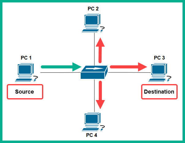
Figure 8.1 – Network hub
As shown in the preceding diagram, PC 1 wants to send a message to PC 3 on the network. PC 1 creates a message in the form of an electrical signal and places the message onto the media (copper cable). When the hub receives the message (electrical signal) from PC 1, it simply rebroadcasts the message out of all other interfaces to all other devices on the network. To put it simply, devices such as PC 2 and PC 4 receive a copy of the message that was only intended for PC 3; this creates a security concern on the network.
Furthermore, imagine that an organization has many more devices and is using a network hub to interconnect all end devices and share resources. As you can imagine, a hub is a non-smart device that simply rebroadcasts incoming signals throughout the network. In a large network with many hubs, each device that sends a message will be rebroadcasted through the entire network, therefore creating excess or unnecessary traffic within various sections of a network, which can lead to network congestion.
A single collision domain is created for all devices that are connected to the hub. A collision domain is simply a segment of the network where a packet collision can occur due to more than one device transmitting a message at a time on a shared network segment. Once packet collision occurs, the message is discarded and the sender has to transmit the message again.
The following diagram shows the effects of using only hubs on a network:

Figure 8.2 – Issues with hubs
As shown in the preceding diagram, Node A sends a message to Node B on the network. However, as the message is transported to the destination, each hub along the way is rebroadcasting and sending a copy of the message to other devices on the network. As a network grows with more hubs and devices, network congestion is bound to happen, which can cause packet loss and high latency. Furthermore, the collision domain increases, as more hosts are connecting to a network with hubs.
Since a network hub simply rebroadcasts messages without inspecting the destination media access control (MAC) address or the destination IP address of a message, what if two different devices send a message to the hub? A network collision will occur, causing the packets from both senders to be corrupted, therefore, only one device can transmit a message at a time while all others have to wait on a hub network. If a network collision occurs and/or the packets are corrupted, the sender of the message will resend the message.
To prevent issues on a hub network, end devices such as computers use Carrier Sense Multiple Access with Collision Detection (CSMA/CD). Before an end device places a message (electrical signal) on the media, the device checks the media for the presence of a signal. If a signal is detected, it means another device is already using the media/network and is transmitting a message. Therefore, the device waits and checks the media again until no signals are detected, and then proceeds to transmit the message. Since a hub network is a shared medium of communication, each device has to check the media before sending a message or else a collision can occur. Since network hubs have a lot of limitations and do not support scalability very well, these are obsolete devices and are not recommended for use on modern networks.
Layer 2 switch
Network switches are intermediary networking devices that operate at Layer 2 of the OSI networking model and allow end devices such as computers, servers, and printers to connect to a network. Additionally, using switches to interconnect devices within an office or building allows network professionals to create a local area network (LAN). A network switch is an intelligent networking device that does not rebroadcast inbound electrical signals to all other interfaces; instead, the network switch inspects the destination MAC address found within the Layer 2 header of a frame to determine the destination host.
To gain a better understanding of how network switches operate, let’s study the following network topology in which three computers are all interconnected using a switch:

Figure 8.3 – Network topology with a switch
As shown in the preceding diagram, each computer is assigned an IPv4 address and has a unique MAC address on its network interface card (NIC). When a switch boots up, it does not know which computer is connected to any of the local interfaces on the switch. Only when a device such as a computer sends a message does the switch inspect the source and destination MAC addresses within Layer 2 of the frame, which is used to populate the content-addressable memory (CAM) table.
Important note
The CAM table is used by Cisco switches to store MAC addresses that are learned by an interface and helps the switch determine how to forward a message to a destination on the network. Each time a frame enters an interface, the switch will check the source MAC address and if the source MAC address was never seen before on the inbound interface, the switch will temporarily store it in the CAM table and map it to the interface. This is how switches populate entries within a CAM table. Keep in mind that the contents of the CAM table are stored in random access memory (RAM), and the contents are lost whenever the switch loses power or reboots.
Let’s imagine that PC 1 wants to send a message to PC 3 but doesn’t know the destination host’s MAC address. What happens next? On a network, all senders will need to include source and destination MAC addresses within the Layer 2 header, and the source and destination IP addresses in the Layer 3 header. Since switches operate at Layer 2, they will not be able to view the Layer 3 header details but only MAC addresses in the Layer 2 header of the frame. Therefore, it’s essential that the source and destination MAC addresses are inserted correctly on a frame before placing the message on the network for delivery.
The Address Resolution Protocol (ARP) allows devices to resolve an IPv4 address to a MAC address on a LAN. To put simply, PC 1 will send an ARP request message with a destination MAC address of FF:FF:FF:FF:FF:FF to the switch, which will broadcast the message to all other interfaces except the interface the message originated on, as shown in the following diagram:

Figure 8.4 – ARP request message
As shown in the preceding diagram, the ARP request message is sent to the switch and is broadcasted to all other interfaces. Additionally, the source MAC address of the frame is stored on the CAM table and is mapped to interface 1, as shown in the following table:
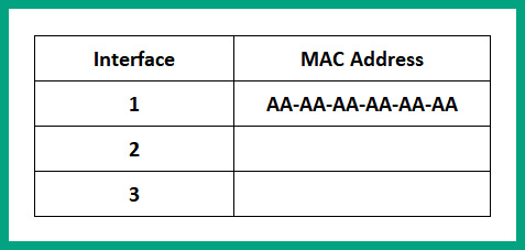
Figure 8.5 – CAM table
Next, PC 2 and PC 3 will receive the ARP request message and inspect the requested target IP address of 192.168.1.30. Since PC 2 has an IP address of 192.168.1.20, it will discard the message and not respond. PC 3 has the target IP address and will respond directly to PC 1 with its MAC address using an ARP reply message.
The following diagram shows an ARP reply message:
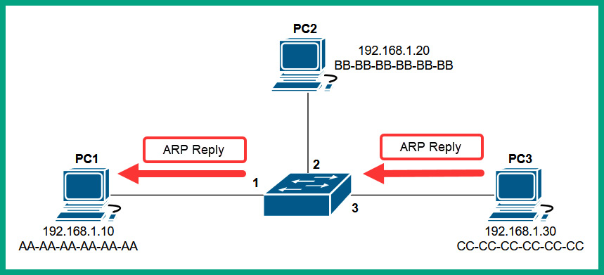
Figure 8.6 – ARP reply message
When the switch receives the ARP reply message from PC 3, it inspects the source and destination MAC. PC 3’s source MAC address is stored within the CAM table and is mapped to interface 3, and the switch forwards the ARP reply directly to the destination host since the switch had previously recorded PC 1’s MAC address on the CAM table.
The following table shows the entries of the CAM table after receiving the ARP reply from PC 3:

Figure 8.7 – CAM table updated
At this point, the switch knows where PC 1 and PC 3 are located based on the entries within the CAM table and their MAC addresses. Additionally, PC 1 knows the MAC address of PC 3 and inserts it within the destination MAC address field of the frame, and sends the message on the network. The switch will inspect the destination MAC address within the Layer 2 header of the frame and check the CAM table to determine which interface knows about the destination MAC address, and forward the message out of interface 3, as shown in the following diagram:

Figure 8.8 – Switching forwarding method
Once a switch already knows PC 3 is connected to interface 3, it sends the message directly to the destination host on the network.
However, there’s another real-world scenario where the sender device (such as a computer) knows the destination host’s MAC address but the switch doesn’t. Whenever a switch receives a frame, it will inspect the destination MAC address and check the CAM table to determine how to forward the message to its destination, as you already know. In the event that a switch does not know the location of the destination host because the MAC address is not found within the CAM table, the switch will flood the message out of all interfaces except the interface the message originated on.
This means all devices that are connected to the switch will receive a copy of the message, except the sender. Each device, upon receiving the message from the switch, will inspect the destination MAC address to determine whether they are the intended recipient or not. If a device receives a message and the destination MAC address of the frame does not match the MAC address of the device, the message is discarded. However, if a device receives a message and the destination MAC address of the frame matches the MAC address of the device’s NIC, the frame is processed and sent to the upper layers of the network model.
Switches help reduce the size of a collision domain as compared to hubs on a network. Since switches are intelligent devices and forward frames to their destination by inspecting the destination MAC addresses, switches are able to isolate a collision to a per-interface level. To put it simply, each interface on a switch represents one collision domain, hence it’s recommended that only one device is connected to each switch interface. Hence, a 48-port switch will contain 48 collision domains.
Tip
Each interface/port on a switch represents one collision domain. Therefore, a switch with eight ports has eight collision domains.
The following diagram shows a representation of collision domains on a switch:

Figure 8.9 – Collision domains
As shown in the preceding diagram, there are four collision domains, and since one device (such as a computer) is attached to each interface on the switch, the possibility of a collision occurring between a computer and the switch is reduced. However, if a device sends a Layer 2 broadcast message with a destination MAC address of FF:FF:FF:FF:FF:FF, the switch will forward the message out of all interfaces, thus creating a single broadcast domain. A broadcast domain is simply described as a network segment that all devices can reach by using a Layer 2 broadcast message.
The following diagram shows a broadcast domain on a network switch:

Figure 8.10 – Broadcast domain
As shown in the preceding diagram, by default, all interfaces on a switch collectively create a single broadcast domain that allows all devices to be reached by a Layer 2 broadcast message. As a network professional, creating smaller Layer 2 broadcast domains helps to improve network efficiency and overall performance.
Layer 3 capable switch
Network switches are commonly referred to as Layer 2 devices that operate at the data link layer of the OSI networking model and have the capabilities to forward frames based on the destination MAC addresses. Nowadays, there are Layer 3 network switches, which operate at the network layer of the OSI networking model. These Layer 3 switches allow network professionals to interconnect and perform routing between different virtual local area networks (VLANs) within an organization.
Large organizations implement VLANs within their physical network, which allows network professionals to logically segment a physical network into small broadcast domains, allowing each department (such as human resources, sales, IT, and so on) to be on their own logical network. Therefore, if a device within the sales VLANs generates a broadcast message, it’s limited to devices within the same VLAN only. Since an organization may have multiple VLANs, hosts within a VLAN will not be able to communicate with devices on another VLAN. To ensure VLANs are able to exchange messages with each other, a Layer 3 device is needed to route traffic between one VLAN and another.
One of the most common Layer 3 devices is a router, which allows network professionals to interconnect two or more different networks together. However, network professionals can use a Layer 3 switch that provides routing functionalities as a router to allow communication between VLANs within an organization. Keep in mind that routers are dedicated Layer 3 devices for forwarding packets that have additional Layer 3 functionalities such as advanced data, security, and voice features. However, a Layer 3 switch can perform both Layer 2 functions and Layer 3 routing functions on a network. Using a Layer 3 switch allows the organization to reduce the cost of a dedicated router on the network to perform inter-VLAN routing.
Bridge
A network bridge is a special networking device that operates at Layer 2 of the OSI networking model and allows network professionals to divide the network into multiple collision domains. If you recall, older networks were built using a hub to interconnect end devices and extend a network within an office space or building. However, the downside of using a hub is it creates a single, large collision domain with all connected devices, which isn’t good for performance and security. To put it simply, if a computer sends a message to a hub, it is rebroadcasted to all devices on the network. Additionally, if two more computers transmit a message at the same time, a packet collision will occur.
The following diagram shows a single, large collision domain that’s created using hubs:

Figure 8.11 – Broadcast domain
Network professionals can implement a bridge into a large collision domain to create two smaller collision domains on a network. The following diagram shows a network topology with two collision domains that are separated by a bridge in the middle:

Figure 8.12 – Creating a smaller collision domain
As shown in the preceding diagram, Collision Domain A is separated from Collision Domain B by a bridge. Therefore, if PC 1 and PC 2 send a message at the same time, a packet collision will occur and affect the devices that are connected to Collision Domain A only, leaving Collision Domain B unaffected. However, if PC 1 sends a broadcast message, all devices (such as PC 2, PC 3, and PC 4) will receive the message because they are still connected to the same broadcast domain.
Router
Routers are Layer 3 devices that operate at the network layer of the OSI networking model and allow network professionals to interconnect two or more different networks together. These are dedicated networking devices that function as the default gateway and forwarding device that allows hosts on one network to communicate with hosts on another network.
Whenever a router accepts an inbound message such as a packet, it inspects the Layer 2 header for the destination MAC address to determine whether the message is intended for the router. If the destination MAC address of the message matches the MAC of the inbound interface of the router, the frame is de-encapsulated and sent up to the network layer of the OSI networking model. At the network layer, the router inspects the destination IP address within the Layer 3 header of the packet and checks the routing table on the router for a suitable route/path to forward the message to its destination.
Each router contains a routing table that contains a number of routes to various destination networks and the internet. The router checks the routing table from top to bottom each time it has to perform a lookup before forwarding a packet. Once a suitable route is found, the router stops the route lookup and processes the information within the matching route.
The following diagram shows a few networks that are interconnected using routers:
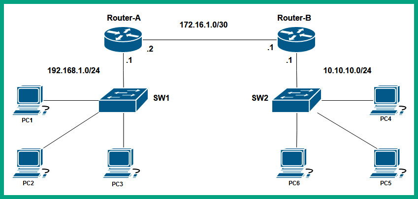
Figure 8.13 – Network diagram
As shown in the preceding diagram, there are three networks that are interconnected using two routers. Each router has a local routing table that tells the router how to forward an incoming packet to its destination. Router-A has two directly connected networks, 192.168.1.0/24 and 172.16.1.0/30. Networks that are directly connected to a router will automatically appear within the routing table when the router boots up. The 10.10.10.0/24 remote network will not automatically appear in the routing table of Router-A by default as it is a remote network and it’s not directly connected. However, the 10.10.10.0/24 and 172.16.1.0/30 networks will automatically be inserted in the routing table of Router-B by default as they are directly connected.
The following snippet shows the routing table of Router-A:

Figure 8.14 – Routing table
As shown in the preceding figure, the routing table of a router such as Router-A contains the following:
- The source of a route that is usually indicated by code
- The destination network
- The next hop address
- The exit interface of the router
Therefore, if PC1 wants to exchange a message with another host such as PC2, it will determine whether PC2 is on the same network as itself or not by calculating the network ID of PC1 and determining whether PC2 is on the same network. Once PC1 determines that PC2 is on a different IP subnet from itself, PC1 sends a message to its default gateway, which is 192.168.1.1 on Router-A’s GigabitEthernet 0/0 interface. Routers will use the destination IP address found within the packet and check the routing table, as shown here:
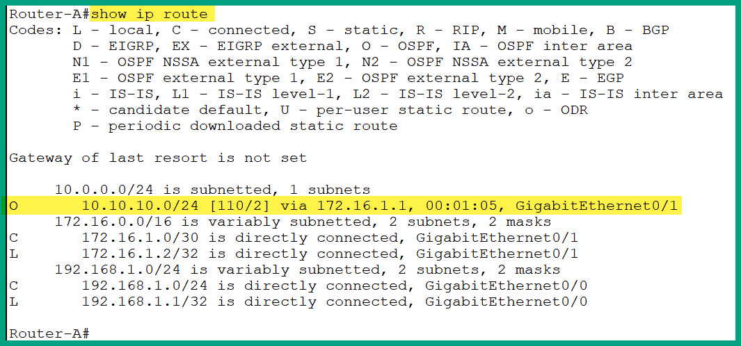
Figure 8.15 – Routing table
Router-A uses the network route that is highlighted in the preceding figure and forwards the packet out of its GigabitEthernet 0/1 interface to Router-B, which is assigned the 172.16.1.1 address. The process is repeated on each router for every incoming packet to determine how to forward the message to its destination, and eventually, the packet will be delivered to the destination. Routers are simply essential networking devices that help network professionals to interconnect different physical and IP networks together.
Each interface on a router represents a collision domain, hence it’s recommended that only one device should be connected to an interface, which prevents packet collisions from occurring. Additionally, each interface on a router is also attached to a broadcast domain, hence routers stop a Layer 2 broadcast from propagating from one network to another.
Let’s study the following network diagram and identify the number of collision domains and broadcast domains:

Figure 8.16 – Network diagram
There are three broadcast domains, as shown in the following diagram:
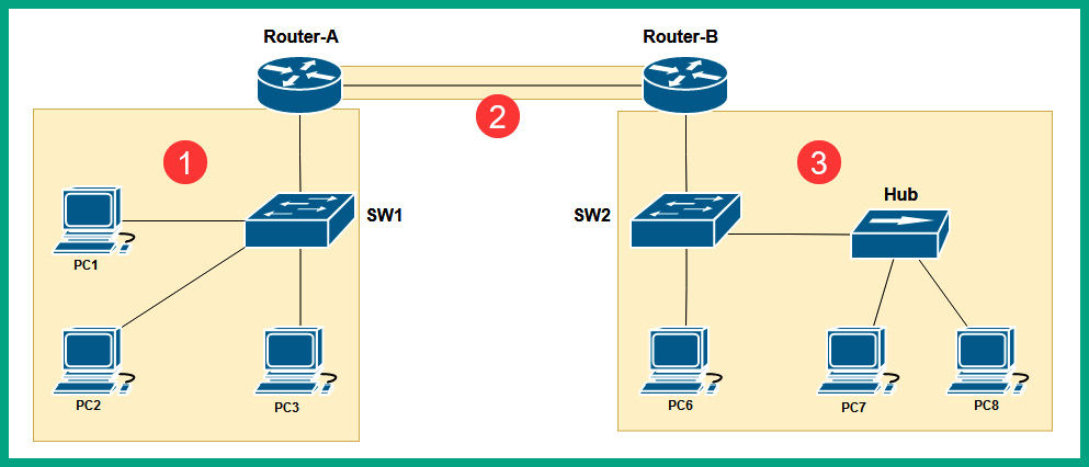
Figure 8.17 – Identifying the number of broadcast domains
There are eight collision domains, as shown in the following diagram:

Figure 8.18 – Identifying the number of collision domains
As a network professional, it is important that you can identify the number of collision domains and broadcast domains. Routers do not forward a Layer 2 broadcast message from one broadcast domain to another.
Access point
An access point (AP) is a networking device that allows Wi-Fi-capable devices to connect to a wired network, allowing users to share resources and access services. While the core of many organizations’ networks is wired connections between devices, wireless networking provides a lot of convenience and support for mobility. Wireless networking allows network professionals to easily extend the capabilities of a wired network to a wireless network by simply connecting an AP to a network switch. Since a network operates at Layer 2 of the OSI networking model, the AP simply generates wireless signals on 2.4 GHz and 5 GHz based on the IEEE 802.11 standards for wireless networking.
Once a client such as a laptop connects to an AP, the client has access to the resources and services on the wired network. Implementing a wireless network allows users to roam around the office with their Wi-Fi-capable devices and work within the vicinity of the AP.
The following diagram shows a small wireless network with an AP:

Figure 8.19 – Wireless network
There are various IEEE 802.11 wireless standards in the wireless networking industry, however, it’s important to know that older APs that use the IEEE 802.11a/b/g/n/ac standards create a contention-based wireless network for all connected clients.
The following steps are written in layman’s terms to provide clarity on how a wireless client proceeds to send a message on a wireless network:
- Client-A wants to send a message to another wireless client that is connected to the same AP.
- Before Client-A transmits the message, it sends a Request to Send (RTS) message to the AP to determine whether the wireless network is clear to send the message.

Figure 8.20 – Requesting status from the AP
- The AP will respond with a Clear to Send (CTS) message if no other devices are transmitting on the wireless network.

Figure 8.21 – AP providing a response
- Then, Client-A will send the message to the AP that is responsible for forwarding it to the destination host on the wireless network.
- The AP will simply rebroadcast the message to all other connected hosts similar to a hub on a wired network.
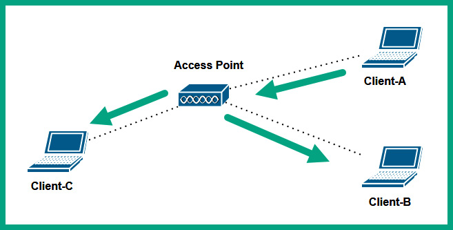
Figure 8.22 – AP forwarding message
As shown in the preceding diagram, all wireless clients that are associated with an AP that operates on IEEE 802.11a/b/g/n/ac wireless standards are all on a single collision domain and broadcast domain.
Wireless networks that use IEEE 802.11a/b/g/n/ac use Carrier Sense Multiple Access with Collision Avoidance (CSMA/CA) to avoid collision of frames on a wireless network. With CSMA/CA, a wireless client will first check with the AP to determine whether the network is clear to send or not. The AP will respond to the client with an all-clear or not. This method prevents collisions of more than one client wanting to transmit a message over the wireless network.
Important note
Newer wireless routers and APs that use the IEEE 802.11ax (Wi-Fi 6) standard do not contain the limitations and shortcomings of previous generations of wireless networking standards. To put it simply, devices that are connected to a Wi-Fi 6 network do not need to use CSMA/CA, as IEEE 802.11ax has improved on forwarding traffic more efficiently, but they can still use RTS/CTS to communicate with legacy APs.
Another type of wireless networking device that’s commonly implemented within small office networks and homes is a wireless router. A wireless router is an all-in-one device that contains the function of an AP, switch, and router in a single device. The AP feature allows the wireless router to create a wireless network on 2.4 GHz and 5 GHz frequencies according to the IEEE 802.11 standard for wireless networking. Furthermore, on the back of a typical wireless router are a few interfaces that are known as switch ports or switch interfaces; these interfaces allow a user to establish a wired connection between their end device and the wireless router. These switch ports operate as a typical Layer 2 network switch, where all devices that are connected to the wireless router using a wired connection will all be able to communicate with each other.
Lastly, the wireless router performs routing functions such as routing traffic between the wireless and wired network. The wireless network is assigned an IP subnet that’s uniquely different from the IP subnet that’s used on the wired network. To put it simply, a smartphone that’s connected to a wireless router will obtain an IP address that’s different from the IP addresses that are being used on the wired LAN.
The following diagram shows a typical wireless network with a wireless router:

Figure 8.23 – Wireless router
As shown in the preceding diagram, PC 1 is assigned an IP address from the 192.168.1.0/24 network, and it’s connected to the wireless router. The wireless router is connected to the wired LAN via the network switch that’s on the 172.16.1.0/24 network. Therefore, the wireless router performs routing between these two different types of networks (wired and wireless) and between the different IP networks.
Wireless LAN controller
A wireless LAN controller (WLC) is a special networking device that allows network professionals to efficiently manage all the wireless access points (WAPs) within an organization from a centralized controller on the network. If an organization has multiple WAPs, the network professionals can simply log in to each device and perform configuration changes, upgrade the firmware, and troubleshoot to resolve any issues.
A few WAPs are just good enough for a small to medium-sized organization with few wireless devices such as laptops and smart devices. However, as the organization provides more wireless devices to employees, network professionals need to ensure the wireless network infrastructure is able to support the increase in wireless devices that are connecting to the wireless network and provide sufficient bandwidth for each device to exchange messages. Therefore, network professionals will implement additional WAPs within the organization to ensure there is sufficient coverage of the wireless signals while eliminating any dead zones, ensuring wireless clients can connect to any WAP within the organization and have access to resources.
As more WAPs are implemented to support wireless clients, network professionals need to continuously monitor the performance of the wireless network to ensure the network is operating optimally. If a WAP is unavailable due to a faulty firmware update or hardware deficiency, wireless clients within the range of the faulty WAP will be affected, and users who rely on the wireless network will be affected as well. Using a WLC allows network professionals to configure each WAP on the network to establish a connection to the WLC. Network professionals can simply log in to the WLC with a web interface and centrally manage the entire wireless network.
For instance, imagine that you need to change the security configurations and methods on a user that can access the wireless network. Traditionally, the network professional will need to log in to each WAP within the organization and perform the configuration changes manually. This method can be time-consuming and often lead to human errors in misconfigurations. The WLC allows the network professional to make the changes directly on the controller, and the WLC will push the configurations to all WAPs within the network automatically to ensure the changes take effect as soon as possible. Additionally, a WLC allows network professionals to determine the firmware version of WAPs, schedule firmware updates, actively monitor the entire wireless network from a single dashboard, and identify issues on the network.
A WLC can be implemented as an on-premises solution or in the cloud. Overall, the WLC is simply a custom operating system or firmware that’s running on a hardware-based device. Each deployment provides its own set of advantages and disadvantages, therefore it’s important to evaluate which type of deployment is most suitable for the organization while providing the most benefits to achieve the objectives.
Load balancer
A load balancer is a special networking device that allows network professionals to distribute the inbound network and application traffic types across a cluster of servers that are providing services and/or resources to users. Imagine that an organization has created a web server and connects it to the internet to host an e-commerce web application to enable the company to sell its products and services to anyone online. For each user on the internet who connects and performs a transaction on the web server, some processing power is used per transaction. As more users connect and perform more transactions, the utilization of computing resources on the server will continue to increase, and eventually, the server will become overwhelmed and perform slowly. As a result, users will be affected due to the slow performance of the server and its incapability to handle a large number of users and their transactions.
One solution is to deploy multiple servers to host the same e-commerce web application, and implement a load balancer device on the network to accept incoming messages from users on the network and distribute the load evenly across the cluster of servers; therefore, one server will not be handling all the transactions. Furthermore, since each server will be able to perform optimally, the load balancer ensures any one server is not overwhelmed with the number of web request messages from the users on the internet.
The following diagram shows a load balancer deployed on a network:

Figure 8.24 – A load balancer on a network
As shown in the preceding diagram, any incoming traffic from users on the internet is intercepted by the load balancer, which is responsible for distributing the network and application traffic types to the group of servers, ensuring each server is not overburdened with a lot of transactions or requests.
Load balancers can be implemented on a network as a hardware-based device or an application that runs on a hypervisor or cloud environment. Load balancers typically operate at either Layer 4 or Layer 7 of the OSI networking model. The Layer 4 load balancers can distribute network traffic based on common transport layer protocols, while Layer 7 load balancers can distribute the load based on common application layer protocols such as Hypertext Transfer Protocol Secure (HTTPS).
Furthermore, load balancers are able to provide fault tolerance; in the event of a server within the cluster being unavailable or offline, the load balancer can simply distribute the incoming load of network traffic to the available servers within the cluster. However, load balancers can operate in an Active/Active state, which allows the distribution of network and application traffic between all active servers within a cluster. They can also operate in an Active/Passive state, which allows the distribution of the load to an active server only and performs a failover to a standby server if the active server is no longer available.
The following are the four most common algorithms that are used by load balancers that determine how the load is distributed to servers on a network:
- Round robin: This is the most common and simplest method that’s used on load balancers to distribute the load to multiple servers. The round robin method simply forwards a request message from a user to each server within the group in turn, and when the load balancer reaches the last server within the group/cluster, it will start again from the first server to the second and third and so on. While this forwarding method is simple, it’s not the most efficient for traffic distribution, as the load balancer assumes each server within the group or cluster is always available, has the same hardware and software specification, and is processing the same amount of load.
- Weighted round robin: This allows the load balancer to distribute the load to each server within a group based on the weight that is assigned to the servers. The weight can be based on a specific criterion that’s usually chosen by the network professional. However, the higher the weight value that’s assigned to a server within the group, the more requests will be forwarded to that specific server and less traffic/load to the servers with a lesser weight value.
- Least connections: The least connections technique is a dynamic load-balancing method that forwards a request to a server within the group that has the least active number of connections. When the load balancer receives a request message from a client on the network, the load balancer checks which server from the group or cluster has the least active connections and forwards the client request to that server.
- Least response time: This is another forwarding method used on load balancers that forwards a request message from a client to the server with the lowest average response time within the group of servers.
Proxy server
A proxy server is simply a server on the network that performs the function of a relay between clients and servers on a network. Proxy servers are commonly implemented by network professionals to prevent hackers from invading a corporate network within an organization, and it does this by intercepting all the messages between the clients and servers.
Within companies, proxy servers are commonly used to perform URL filtering by inspecting the destination URL that a user is trying to reach. If the URL is within the blacklist of web addresses, the proxy server does not forward the client request to the destination. However, if the destination URL exists within the whitelist of allowed web addresses, the proxy server forwards the message to the destination server.
The following diagram shows a proxy server on a network:

Figure 8.25 – Proxy server on a network
As shown in the preceding diagram, when PC 1 wants to send a message to the public server on the internet, PC 1 is configured to forward all web request messages to the proxy server on the network for inspection. Then, the proxy server will check the destination URL and determine whether it’s allowed or denied. If the web request is permitted, the proxy server forwards the message to the web server. When the web server responds, the proxy server intercepts the response messages and caches the data before forwarding a copy to PC 1.
Important note
WAPs or wireless routers can also function as proxy servers on a network.
Proxy servers are common in performing the caching of content; therefore, when a client sends a web request to the proxy server, it checks its cache to determine whether the data already exists or not. If a cached version of a web page already exists within the memory of the proxy server, it is sent to the client on the network. Caching helps an organization reduce the amount of internet bandwidth consumption; however, the cache also means there’s the likelihood that an outdated version of a web page is sent to a client.
The following are common types of proxy servers:
- Forward proxy – This is a common type of proxy that intercepts a client’s request message and forwards it to the destination on the internet
- Reverse proxy – This type of proxy server intercepts and forwards the request message from devices that are on the internet to the servers on the internal network of the organization
Nowadays, proxy servers are still implemented as dedicated devices on a network, however, many next-generation firewalls are able to perform content and URL filtering. However, proxy servers are able to perform content caching that security appliances such as firewalls are unable to do in a large-scale environment, hence, there is still a need for implementing dedicated proxy servers within a network.
Internet modems
A cable modem is simply the customer premises equipment (CPE) that is provided by an internet service provider (ISP) to terminate the cable modem termination system (CMTS) network that is distributed over coaxial cables. The cable modem performs the function of a router, switch, and access point in one unified device.
The following diagram shows a simple representation of the CTMS network:

Figure 8.26 – CMTS network
As shown in the preceding diagram, the ISP implements the CMTS network infrastructure and distributes the cable TV and internet services over the hybrid fiber-coaxial (HFC) infrastructure to their customers. A cable modem is installed at the customer’s location to interconnect the customer’s private network to the HFC and CMTS infrastructure to access internet services.
As you may have realized, modems are all-in-one devices that perform multiple roles such as functioning as a router between the customer’s and the ISP’s networks, operating as a switch to allow the customer to physically connect a few devices, and providing a wireless signal as an AP to allow users to connect their wireless capable devices.
Digital subscriber line (DSL) modems are another type of modems provided by ISPs that distributes internet services over the public switched telephone network (PSTN) lines, sometimes called the plain old telephone service (POTS) lines.
The following diagram shows a representation of a typical PSTN network with a DSL modem:

Figure 8.27 – DSL modem
As shown in the preceding diagram, the DSL modem is installed at the customer’s location, and terminates and converts the signals from the ISP’s network, allowing the devices within the customer’s network to access the internet services.
Repeater
A repeater, sometimes referred to as a Wi-Fi extender/repeater, is a Layer 1 device that simply accepts a signal and regenerates the same signal at a higher power. These devices can be commonly found on wireless networks that are implemented by network professionals within a building or compound area. An AP contains one or more antennas that are used to emit a radio frequency signal, allowing wireless clients to connect to the AP and share resources. However, the antennas of an AP or wireless router can only emit a signal that is strong enough to travel over a certain distance before it starts getting weaker as the distance increases.
Physical obstacles such as concrete and steel walls absorb the wireless signals, therefore, preventing the signals from traveling further away from the AP. Hence, network professionals implement repeaters in strategic locations within their building or compound to capture the signals from the APs and regenerate the same signal. This technique helps reduce dead zones within the wireless network, ensuring there is maximum coverage of the wireless signals for all wireless clients within the organization.
Voice gateways and media converters
Voice gateways allow an organization to interconnect their enterprise Voice over IP (VoIP) network to the telecommunication service provider’s network using various connectivity methods such as PSTN and Session Initiation Protocol (SIP) technologies. Within an organization, you will commonly find a VoIP network with IP phones, a unified communication server (UCS), and networking devices configured to perform the routing of calls between users within the organization. Using a voice gateway allows users to establish calls outside the organization’s network using a telecommunication service provider.
Media converters are specialized networking devices that allow network professionals to easily convert an ethernet communication protocol from one media type to another. For instance, if a network professional wants to interconnect a fiber optic cable to a switch that supports only ethernet interfaces, using a media converter allows the light signals from the fiber optic cable to be converted to electrical signals for the ethernet cable, and vice versa.
Having completed this section, you have learned about the roles and functions of various networking devices that are commonly implemented within organizations to create networks. In the next section, you will discover the roles of various security appliances and how they are used to help protect a network.
Exploring security appliances
Cybersecurity is one of the most demanding fields within the IT industry, as threat actors such as hackers are always looking for new ways to compromise systems and networks within organizations and steal their data. Security appliances are specialized devices that are designed to protect a system or a network from cyber-attacks and threats. In this section, you will learn about the roles and features of firewalls, intrusion detection systems (IDSs), and intrusion prevention systems (IPSs) on systems and networks.
Firewall
A firewall is a network-based security appliance or host-based application that is designed to filter malicious traffic between networks. Network security professionals commonly implement network-based firewalls between the corporate network of their organization and the internet. The intention is to filter any potentially dangerous traffic originating from the internet that’s attempting to enter the private network of the organization.
The internet is the most unsafe network in the entire world and organizations need to monitor and filter network traffic to and from their networks. While it’s important to filter inbound traffic from the internet, it’s equally important to filter outbound traffic from the corporate network to the internet. If an organization’s network is compromised with malware, it usually attempts to infect other systems on the internet. By using a firewall to monitor and filter outbound traffic, network security professionals are able to detect and block any potentially malicious traffic that’s also leaving the organization, preventing the threat from spreading to devices on the internet.
The following diagram shows a typical hardware-based firewall that’s implemented within a company:

Figure 8.28 – Network-based firewall
As shown in the preceding diagram, a network-based firewall is implemented to filter traffic between the internet and the corporate network of an organization. The advantages of using a network-based firewall are it’s a hardware-based device that sits between two or more networks and has the capabilities of filtering traffic between those networks. However, network-based firewalls have to be carefully configured by a security professional to efficiently filter traffic. If a firewall is misconfigured, malicious traffic can be allowed from the internet to the internal networks of the organization. Additionally, threat actors may be able to discover the security vulnerability within the misconfiguration of the security appliance and exploit it.
Next-generation firewalls are able to perform deep packet inspection (DPI) by decrypting any encrypted packets to inspect the Layer 7 protocol for any potential threat or malware that may be embedded within an application-layer protocol. Additionally, next-generation firewalls are able to perform data loss prevention (DLP) to prevent employees from sending confidential data and files outside the organization’s network; however, these are just a few of the many features within firewalls that help network security professionals to protect their organization’s assets.
When deploying network-based firewalls, it’s important to identify the following security zones:
- Outside zone: The outside zone is identified as a network that does not belong to the organization such as the internet. Traffic that originates from the outside zone is considered to be unsafe and not trusted, therefore, any interface in the firewall that’s assigned to the outside zone has a security level of 0 by default. The firewall will automatically not permit any traffic that is originating from any interfaces that have a security level of 0 by default.
- Inside zone: The inside zone is identified as a network that is managed by the organization, and is usually the internal corporate network within the company. The inside zone is usually assigned a security level of 100, which is fully trusted by the firewall. Therefore, any traffic that originates from the inside zone will automatically be permitted to access any other networks or zones that are attached to the firewall.
- Demilitarized zone (DMZ): The DMZ is a semi-trusted zone within the organization’s network that allows network professionals to deploy and implement servers that are accessible to users on the internet. For instance, network professionals will implement an on-premises email server within the DMZ and configure a firewall with very strict rules to allow specific traffic types to an email server. Since the DMZ is a semi-trusted segment of the organization’s network, security professionals usually configure the DMZ with a security level of 50.
The following diagram shows all three zones attached to a network-based firewall:

Figure 8.29 – Security zones on a firewall
The security levels assigned to each zone are very important as they determine whether the firewall will permit or deny traffic between a zone. By default, Cisco firewall appliances allow traffic that originates from a zone with a higher security level to a zone with a lower security level, while denying traffic originating from a zone with a lower security level to a zone with a higher security level. Put simply, the firewall does not trust traffic originating from zones with lower security levels.
By default, the following rules are applied to a network-based firewall:
- Traffic originating from the inside zone is permitted to the DMZ
- Traffic originating from the inside zone is permitted to the internet
- Traffic originating from the DMZ is not permitted to the inside zone
- Traffic originating from the DMZ is permitted to the outside zone
- Traffic originating from the outside zone is not permitted to the inside zone
- Traffic originating from the outside zone is selectively permitted based on the firewall rules to the DMZ
Important note
Packet filtering firewall rules are created using the five tuples: source IP address, destination IP address, source port number, destination port number, and protocol. The five tuples are used to identify a flow/stream of traffic between a source and a destination. Therefore, when creating a firewall rule to permit or deny traffic, it’s important that the network security professional has a clear understanding of the source and destination of the traffic flow.
There are host-based firewalls that are simply security applications that are installed on a host device such as a computer with the capabilities of filtering network traffic entering and leaving the host device. Unlike network-based firewalls, which can filter traffic between networks, host-based firewalls are capable of filtering traffic on the host device only.
The following snippet shows the Windows Defender Firewall on a Windows 11 device:

Figure 8.30 – Host-based firewall
Many operating systems, such as Microsoft Windows and various flavors of Linux, have a built-in native firewall that filters traffic on the host device. However, many antimalware applications provide a third-party host-based firewall to improve threat detection and prevention. Whether there’s a network-based firewall implemented within an organization’s network, it’s recommended to ensure all host-based firewalls are enabled on all client and end devices.
Imagine that an organization has disabled all their host-based firewalls within the entire company and implemented a single network-based firewall between their corporate network and the internet. The network-based firewall is a single layer of protection and failure, and if it is misconfigured or unable to detect malware entering the corporate network, the malware can easily spread to all end devices within the company’s network. If the host-based firewall is disabled on each end device, there is nothing really stopping the malware from attempting to compromise other hosts within the internal network. Hence, it’s important to ensure host-based firewalls are enabled at all times. Both host- and network-based firewalls can be configured to allow and block traffic as needed, therefore network security professionals should configure firewall rules accordingly rather than disable a firewall completely.
IPS/IDS
An IDS is a reactive security solution system that is used to inspect network traffic, detect whether an intrusion is found within a packet, and send an alert if an intrusion is found. An IDS is considered to be reactive because it will trigger an alert after a security intrusion is detected but does not stop the cyber-attack or threat on the network.
Since IDSs do not have the capability of stopping an intrusion as it occurs on a network, the IDS sensor is connected to a network switch that is configured within a switched port analyzer (SPAN). The SPAN port is simply a dedicated interface on the network switch that takes a copy of the network traffic that is flowing between a source and destination through the switch and out the SPAN port to the IDS sensor.
The following diagram shows an IDS sensor connected to a SPAN port on a switch:
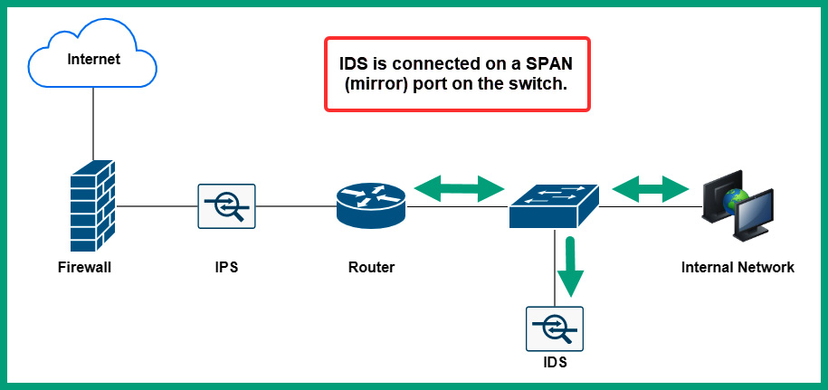
Figure 8.31 – IDS sensor on a network
As shown in the preceding diagram, the IDS sensor receives a copy of the network traffic passing through the switch for analysis. If an intrusion is detected, the IDS reacts and triggers an alert but does not stop the attack as it’s happening on the network. IDSs are commonly used by security professionals to understand how attacks occur on a network and what the objectives of a threat actor are. Using intelligence collected from an IDS can provide a lot of information on how hackers are performing new and sophisticated cyber-attacks.
The IPS is a proactive security solution system that sits in line with network traffic, inspecting and detecting any intrusions. If an intrusion is detected, the IPS immediately blocks the intrusion and sends an alert. Unlike the IDS, the IPS has the capability of stopping an intrusion as it occurs on the network.
The following diagram shows an IPS on a network:
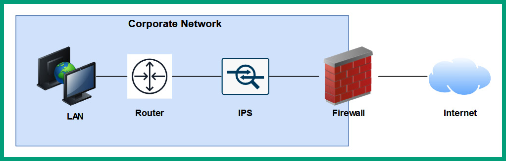
Figure 8.32 – IPS on a network
As shown in the preceding diagram, the IPS is placed between the network-based firewall and the internal network of the organization. Some firewalls are not able to detect intrusions within various traffic types, hence the need for a detected security solution that has the capabilities of detecting intrusions that are missed by the firewall on the network. Additionally, the IPS is placed behind the firewall and inspects traffic that is entering and leaving the corporate network only, hence the reason for its placement between the firewall and corporate network.
Years ago, network-based intrusion detection systems (NIDSs) and network-based intrusion prevention systems (NIPSs) were detected as hardware-based security appliances. Nowadays, these are built into next-generation firewalls and are activated with a software license from the firewall vendor.
There are host-based intrusion detection systems (HIDSs) and host-based intrusion prevention systems (HIPSs) that are security applications installed on host devices such as computers. HIDSs and HIPSs have the same function as the network-based deployment with the exception that HIDSs and HIPSs can only monitor the security events within a host. They can also monitor network traffic coming into the host. Additionally, they are often used as file integrity checkers.
The following are the four types of alerts that are generated by an IDS and IPS:
- False positive: An alarm is triggered, but no threats exist
- False negative: No alarm is triggered, but a threat does exist
- True positive: An alarm is triggered, and a threat does exist
- True negative: No alarm is triggered, and no threat exists
Network security professionals continuously improve the rules within an IDS and IPS to ensure there are fewer false positives and false negatives. Therefore, each alert has to be investigated by a security professional to determine whether it’s a real security intrusion or not.
Having completed this section, you have learned about the roles and functions of firewalls, and IDS and IPS security appliances on a network. In the next section, you will discover various networked devices that are commonly found within organizations and homes.
Types of networked devices
Within a network, there are many host and client devices that can be found within organizations and even home networks. The following is a list of common networked devices:
- VoIP phone.
- Printers can be connected to a network, allowing all users to share the resource simultaneously.
- Physical access control devices.
- IP cameras can connect to a wired and/or wireless network, allowing a user to remotely access and manage the cameras.
- Heating, ventilation, and air conditioning (HVAC) sensors are implemented within a data center to detect changes in the temperature of the room. The sensors communicate with the HVAC system to ensure the temperate is properly controlled within the room to ensure all devices are cooled.
- Internet of Things (IoT) devices such as smart refrigerators, smart speakers, smart thermostats, and smart doorbells.
- Industrial control systems (ICS) such as supervisory control and data acquisition (SCADA) systems are systems that are implemented within an industrial plant that automate and control many processes for the day-to-day operations of the facility.
Having completed this section, you have discovered common networked devices that are commonly found within an organization and home network.
Summary
During the course of this chapter, you have explored the roles and functions of a wide range of networking devices and security appliances that are commonly implemented within organizations to forward traffic between a source and a destination. Additionally, you have explored the need for security appliances and solutions such as firewalls, IDSs, and IPSs within a network. Lastly, you have gained insights into the type of devices that are connected to a network, such as IoT devices.
I hope this chapter has been informative for you and is helpful in your journey toward learning about networking and becoming a network professional. In the next chapter, Chapter 9, Routing and Switching Concepts, you will explore various routing protocols and how they work to ensure routers are able to forward packets to their destinations, and various switch configurations that are used to segment a physical network to improve performance.
Questions
The following is a short list of review questions to help reinforce your learning and help you identify areas that require some improvement:
- Which of the following devices operates at Layer 1?
A. Router
B. Hub
C. Firewall
D. Switch
- Which of the following devices is used to interconnect different networks?
A. Firewall
B. Hub
C. Switch
D. Router
- Which of the following devices is used to manage all the APs within an organization?
A. WLC
B. Bridge
C. WAP
D. Switch
- Which of the following devices can be used to forward traffic between VLANs?
A. Layer 2 switch
B. Bridge
C. Hub
D. Layer 3 switch
- Which of the following can a network professional use to distribute network traffic between multiple servers on a network?
A. Router
B. Layer 3 switch
C. Load balancer
D. Proxy server
- Which of the following devices is provided by the ISP to interconnect a customer network to their CMTS network?
A. Bridge
B. Cable modem
C. Router
D. DSL modem
- Which of the following wireless standards does not need to use CSMA/CA?
A. IEEE 802.11ax
B. IEEE 802.11a
C. IEEE 802.11n
D. IEEE 802.11ac
- Which of the following blocks an intrusion on a network?
A. HIPS
B. NIDS
C. HIDS
D. NIPS
- Which of the following alert types is best used to describe when no threat exists on a network and an alert is generated?
A. False negative
B. True negative
C. False positive
D. True positive
- Which of the following methods is used to prevent collisions on a wired contention-based network?
A. CSMB/CD
B. CSMA/CD
C. CSMD/CA
D. CSMA/CA
Further reading
To learn more on the subject, check out the following links:
- What is a next-generation firewall? https://www.cisco.com/c/en/us/products/security/firewalls/what-is-a-next-generation-firewall.html
- What is a Wireless LAN Controller? https://www.cisco.com/c/en/us/products/wireless/wireless-lan-controller/what-is-wlan-controller.html
- What is an IPS? https://www.vmware.com/topics/glossary/content/intrusion-prevention-system.html