
5
Applied IPv4 Subnetting
In this chapter, you will learn about the importance of the subnet mask and its role in helping network professionals determine the network and host portions of an address, and helping networking devices make forwarding decisions. Additionally, you will learn how to calculate the network prefix and network ID of IPv4 addresses and use subnetting techniques to create smaller network blocks to improve the efficiency of a network.
In this chapter, we will cover the following topics:
- Understanding the purpose of the subnet mask
- Delving into network prefixes and subnet masks
- Determining the network ID
- Understanding the purpose of subnetting
- IPv4 subnetting and VLSM
Let’s dive in!
Understanding the purpose of the subnet mask
Both IPv4 and IPv6 addresses have an accompanying subnet mask. The subnet mask plays a very important role within the network and helps a sender device determine whether to forward a message to the default gateway or not. The following are the important key characteristics of the subnet mask and its responsibilities:
- An IPv4 subnet mask has the same length as an IPv4 address, which is 32 bits in length, while an IPv6 subnet mask is 128 bits in length.
- The subnet mask is used with an IPv4 or IPv6 address to help devices identify the network and host ports of the IP address.
- The subnet mask is used to help devices and network professionals determine the total number of IP addresses and usable (assignable) addresses within an IP network.
- The subnet mask helps a sender device determine whether the destination host is on the same IP network as the sender or on another network. If the destination host is on another IP subnet, the sender forwards the message to the sender’s default gateway.
The following table shows the default subnet mask for each class of IPv4 addresses on both a private and public network:

Figure 5.1 – Default subnet masks
As shown in the preceding table, the default subnet masks are assigned to their respective IPv4 address classes. When working with classful addresses, an IPv4 Class A address such as 10.10.10.1 will be assigned a default subnet mask of 255.0.0.0. On the other hand, an IPv4 Class B address of 172.16.4.3 will be assigned a default subnet mask of 255.255.0.0 and an IPv4 Class C address of 192.168.1.20 will be assigned a default subnet mask of 255.255.255.0.
Next, you will explore the principles of creating a network prefix when working with IPv4 addressing by using the information found within the subnet mask.
Delving into network prefixes and subnet masks
In this book, you may have seen various IPv4 and IPv6 addresses written in the format of 192.168.1.1/24 or 2001:DB8:0:1111:FE99:47FF:FE75:CEE0/64 and you’re wondering what the /24 and /64 values are at the end of the IP addresses. The /x value that’s appended to the end of the IP address is referred to as the network prefix and represents the subnet mask in a simplified format. Additionally, the x value is calculated based on the total number of bits, which are 1s within the subnet mask of the IPv4 or IPv6 address.
To gain a better understanding, let’s consider an IPv4 address such as 10.1.2.3, which has a default subnet mask of 255.0.0.0. The following table shows the binary notation of the Class A subnet mask:

Figure 5.2 – Class A subnet mask
As shown in the preceding table, there are a total of 8 bits, which are 1s within the subnet mask. Therefore, the network prefix is /8. Rather than writing the entire subnet mask with an IPv4 or IPv6 address, network professionals can simply append the network prefix at the end of an IP address.
The following table shows the binary notation of each default class of subnet mask:

Figure 5.3 – Subnet masks
As shown in the preceding table, the following are the network prefixes for each default subnet mask:
- Class A: 255.0.0.0 - /8
- Class B: 255.255.0.0 - /16
- Class C: 255.255.255.0 - /24
Additionally, the subnet mask helps network professionals and devices determine the network and host portions of an IP address. The network portion of the IP address is the same for all devices within the same IP network, while the host portion of the IP address is unique to the interface of the end device only.
To determine the network and host portion of an IP address, you can simply convert both the IP address and subnet mask into binary notation, as shown in the following table:

Figure 5.4 – network ID of Class A
As shown in the preceding snippet, the 1s within the subnet mask that are aligned with the bits within the IP address are used to identify the network portion of the address, while the 0s within the subnet mask that are aligned to the remaining bits within the IP address indicate the host portion of the address. Placing a dotted line after the last 1 within the subnet mask will help you quickly identify the network and host portions of both IPv4 and IPv6 addresses.
Next, let’s look at identifying the network and host portion of a Class B address that uses the default subnet mask:
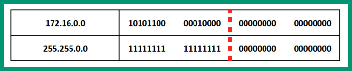
Figure 5.5 – network ID for Class B
As shown in the preceding table, the first 16 bits within the subnet mask are all 1s, which indicates the first 16 bits within the IP address represent the network portion of the address. The bits that are 0s within the subnet mask indicate the host portion of the IP address.
Lastly, let’s look at identifying the network and host portion of a Class C address that uses the default subnet mask:
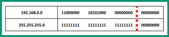
Figure 5.6 – network ID for Class C
As shown in the preceding table, the subnet mask indicates the first 3 octets (24 bits) within the IP address representing the network portion and the last octet (8 bits) represents the host portion of the address.
During your journey in the field of network, you will commonly discover networks are using custom subnet masks such as 255.255.224.0. To calculate the network prefix, simply convert each octet from decimal into binary, as shown in the following steps:
- Converting the first octet, 255, into binary will be 11111111.
- Converting the second octet, 255, into binary will be 11111111.
- Converting the third octet, 224, into binary will be 1110000.
- Converting the fourth octet, 0, into binary will be 0000000.
- Lastly, calculating the sum of all bits that are 1s from each octet will provide a network prefix of /19.
The following table shows a classless IPv4 address with a custom subnet mask:
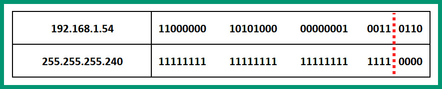
Figure 5.7 – Custom subnet mask
As shown in the preceding table, the 1s within the subnet mask represent the network portion of the IP address, which is the first 28 bits. The 0s within the subnet mask represent the host portion of the address, which is the last 4 bits.
Now that you have the skills to both describe and understand the purpose of the network prefix, next, you will learn how to use a subnet mask to determine whether a destination host is on the same network as the sender.
Determining the network ID
During my experience within the networking industry, I have seen IT professionals mistakenly configure the incorrect IP address and/or subnet mask on devices within their network. As an aspiring network professional, it’s important to understand how to identify whether devices are on the same IP network or not. Let’s take a look at the following network topology, which contains a computer, a switch, and a router:

Figure 5.8 – Network topology
As shown in the preceding diagram, there’s a small network that contains a computer with a label of PC 1 that has an IPv4 address of 192.168.1.126 that uses a custom subnet mask of 255.255.255.128. On the same network, there’s a router as the default gateway that provides access to the internet, which is configured using an IPv4 address of 192.168.1.129 with a custom subnet mask of 255.255.255.128.
In this scenario, the computer is connected to the same physical network as the router. If the computer has to send a message to a host on the internet, the computer forwards the traffic to its default gateway on the network. However, looking closely at the IPv4 addresses on both PC 1 and Router 1, it seems like both devices are on the same IPv4 network, right? What if I told you that these two devices are not on the same IP network and won’t be able to communicate with each other?
To determine why PC 1 and Router 1 will not be able to communicate with each other, you need to calculate the network IDs of each device. The network ID allows network professionals to identify which IP network a host belongs to. While devices within an organization are all interconnected to the same physical network, network professionals create unique IP subnetworks (subnets) where each subnet has a network ID, a range of usable IP addresses, and a broadcast address.
To determine the network ID of a host, devices and network professionals use a logical operation known as ANDing. The process of ANDing allows a system to accept two input values and provide a single output. The following are the laws of ANDing:
0 AND 0 = 0
0 AND 1 = 0
1 AND 0 = 0
1 AND 1 = 1
Using the laws of ANDing, devices and network professionals AND the IP address of a device against the subnet mask, the result of which is the network ID. Let’s determine whether the computer and router are on the same IP subnet by following these steps:
- First, let’s convert the IPv4 address and the subnet mask of the computer into binary notation, then use the laws of ANDing to determine the network ID of the computer:

Figure 5.9 – PC 1’s Network ID
As shown in the preceding diagram, the network ID for PC 1 in binary notation is 11000000.10101000.00000001.00000000. Converting the binary notation into decimal will provide the network ID of the router as 192.168.1.0/25.
- Next, let’s covert the IPv4 and subnet mask of the router into binary notation and use the laws of ANDing to determine the network ID, as follows:

Figure 5.10 – The router’s network ID
As shown in the preceding diagram, the network ID for the router in binary notation is 11000000.10101000.00000001.10000000. Converting the binary notation into decimal will provide the network ID of the router as 192.168.1.128/25.
- Lastly, let’s compare the network IDs of both PC 1 and the router. PC 1 has a network ID of 192.168.1.0/25 and the router has a network ID of 192.168.1.128/25. Since these network IDs are not the same, this means PC 1 and the router are not on the same IP subnet. Therefore, they will not be able to communicate with each other, even though they are connected to the same physical network.
Now that you’ve gained the skills to determine the network ID of a device by ANDing the IP address and subnet mask, next, you will learn about the importance of subnetting in the networking industry and how to calculate the total and usable IP addresses within a network.
Understanding the importance of subnetting
Imagine you’re a network professional for an organization that has six branch offices within various cities of your country. Each branch office has no more than 50 end devices that need an IPv4 address. Your job is to assign an appropriate IPv4 addressing scheme within the entire organization to support all the remote offices and devices. At first, it will be very easy to assign a unique private IPv4 Class C address block to each of the six branches to meet the required number of IPv4 addresses per remote office, as shown:
- Branch office 1: 192.168.0.0/24
- Branch office 2: 192.168.1.0/24
- Branch office 3: 192.168.2.0/24
- Branch office 4: 192.168.3.0/24
- Branch office 5: 192.168.4.0/24
- Branch office 6: 192.168.5.0/24
While this IPv4 addressing scheme will work, it’s not the most efficient scheme as there will be a lot of wastage of IPv4 addresses within each of the six branch offices. Let’s take a closer look at why this is not the best solution:
- First, let’s use the following formula to calculate the total number of IPv4 addresses within a single IPv4 network block:
Total IPv4 addresses = 2H
The total number of IPv4 addresses includes the network ID, the range, and the broadcast addresses within a network. The H value represents the number of host bits within the address.

Figure 5.11 – Determining host bits
As shown in the preceding table, the bits that are 0s within the subnet mask represent the host portion of the IP address. Therefore, there are 8 host bits within the address.
- Next, substituting the value of H = 8 in our formula provides the following results:
Total IPv4 addresses = 2H
= 28
= 256
There are a total of 256 IPv4 addresses within a Class C network that uses the default subnet mask; this includes the network ID, the usable addresses, and the broadcast address.
Important note
When calculating the number of IP addresses that can be assigned to devices, we need to exclude the network ID and the broadcast addresses as these two addresses are not assignable to any device on an IPv4 network.
Usable IPv4 addresses = 2H – 2
Since there are 8 bits within any of the Class C address blocks that use the default subnet mask, the following calculations provide the results of usable IPv4 addresses:
Usable IPv4 address = 2H – 2
= 28 – 2
= 256 – 2
= 254
To conclude, there are 254 usable IPv4 addresses per Class C network that uses a /24 network prefix.
If you were to implement a unique Class C network block within each of the six remote branches of the organization, there would be a huge amount of IP addresses being wasted. Therefore, using classful addressing with default subnet masks isn’t the most suitable solution in some cases. Using a classless addressing scheme allows network professionals to create smaller networks with custom subnet masks with fewer usable IP addresses to avoid wastage by using a technique known as subnetting.
Subnetting provides the following benefits to organizations and network professionals:
- To efficiently distribute IP addresses with the least wastage
- To create more networks with smaller broadcast domains
So far, you have seen the importance of minimizing the wastage of IPv4 addresses within private and public networks. However, a large broadcast domain within an organization can affect the performance of the network. Imagine that there are 500 end devices such as computers, servers, and Internet of Things (IoT) devices, all interconnected to the same IP network. Each time a device sends a broadcast message, it’s propagated throughout the entire network and all devices receive a copy of the message and process it. If more devices are generating broadcast messages on the network at the same time, these messages will eventually saturate the available bandwidth on the physical network, causing other traffic types such as voice and video to be discarded. Voice and video traffic types use User Datagram Protocol (UDP) as their preferred transport layer protocol as UDP is better for time-sensitive applications. However, since UDP does not provide reliability or guarantee of delivery, UDP traffic is most likely to be discarded when the network becomes saturated.
To reduce the size of a broadcast domain, subnetting allows network professionals to create smaller IP networks to support fewer devices. For example, while all devices are interconnected to the same physical network within an organization, a network professional can create a unique subnet for each department within the company such that the human resource team will be on a unique IP subnet, the accounting team will be on another IP subnet, and so on. If a device within the human resources team is generating broadcast messages, it’s limited to the human resources IP subnet and will not propagate to another IP subnet within the organization. Therefore, other departments will not be affected and the broadcast messages are contained while improving the performance of the entire network.
Having completed this section, you have discovered the importance of subnetting and gained the hands-on skills to calculate the number of addresses within a network. Next, you will gain the hands-on experience that network professionals have to perform subnetting and VLSM.
IPv4 subnetting and VLSM
To further understand how subnetting helps network professionals, let’s take a deeper dive into getting the hands-on skills on breaking down an IP address block to create subnets for an organization. In this exercise, let’s imagine you’re the network administrator or network engineer for a fictional organization that has a total of four offices that are interconnected using a Wide Area Network (WAN) solution, as shown in the following network topology:

Figure 5.12 – Network topology
Your objective is to create an IPv4 addressing scheme for the entire organization, ensuring each office location has an IP subnet and that there’s the least wastage of IP addresses per subnet. The following sub-sections will guide you through the process of subnetting.
Step 1 – determining the appropriate IPv4 block
To get started with subnetting as a network professional, you will need to determine the total number of networks within the organization and the size of the largest network. Three WAN networks are used to interconnect the remote branches to the main office and four Local Area Networks (LANs) within each office location, which is a total of seven networks.
Determining the number of networks and the size of the largest network within an organization helps you choose an appropriate address class for the organization. Each address class supports a unique amount of IPv4 networks and addresses based on their default subnet masks.
In this step, we’ll be using the default subnet masks to help us determine the total number of IPv4 addresses within each IPv4 address class. The 1s within the subnet mask represent the network portion, while the 0s represent the host portion of the address, as shown in the following table:

Figure 5.13 – Subnet masks
Using the 2H formula to calculate the total number of IPv4 addresses per class, the following results show the total size of each network per address class:
- Class A = 224 = 16,777,216 total IP addresses
- Class B = 216 = 65,536 total IP addresses
- Class C = 28 = 256 total IP addresses
To get a more realistic result, it’s important to remember that the network ID and broadcast addresses can’t be assigned to any device on an IPv4 network and need to be excluded to determine the usable number of IPv4 addresses that can be assigned to hosts on a network. Therefore, using the 2H – 2 formula, to calculate the number of usable IPv4 addresses, the following results show the available IPv4 addresses per address class:
- Class A = 224 – 2 = 16,777,214 usable IP addresses
- Class B = 216 – 2 = 65,534 usable IP addresses
- Class C = 28 – 2 = 254 usable IP addresses
Since we have already determined the number of networks within the organization, the following is a further breakdown listing the size of each network:
- Main Office LAN: 28 hosts
- Branch A LAN: 26 hosts
- Branch B LAN: 25 hosts
- Branch C LAN: 15 hosts
- WAN 1 (R1-R2): 2 IPs are needed
- WAN 2 (R2-R3): 2 IPs are needed
- WAN 3 (R3-R4): 2 IPs are needed
Implementing a Class A address block within the organization will result in over 16 million addresses being wasted since the largest network within the company has 28 host devices. Using a Class B address block with 65,534 usable IPv4 addresses will result in wastage of addresses too. However, using a Class C network block may seem to be the most appropriate as it’s the small address Class with 254 usable IPv4 addresses.
Important note
When creating subnets, the size of each subnet should be able to fit the largest network within an organization.
Now that we’ve determined that a Class C address block will be appropriate for the organization, in the next step, you will learn how to further evaluate whether a single Class C address block can be broken down into seven subnets to fit each network in the company.
Step 2 – creating new subnets (subnetworks)
When creating subnets, it’s important to convert the address block from dotted-decimal notation into binary notation as it helps easily identify the network and host portions of the address. Additionally, to create new subnets from an address block, you will need to convert some of the host bits into new network bits. This allows us to create more networks while reducing the number of IPv4 addresses that are available within each subnet.
Let’s get started by using the first available Class C address block of 192.168.0.0/24 and converting both the address and default subnet mask into binary notation, as shown in the following table:

Figure 5.14 – Network block and default subnet mask
As shown in the preceding table, the 1s within the subnet mask represent the network portion of the IP address and the 0s represent the host portion of the address. Simply put, the first 24 bits represent the network portion and the last 8 bits represent the host portion of the number. This means that all hosts within the 192.168.0.0/24 network will have the same network portion of the IPv4 address, while the host portion will be unique to the individual host device on the network.
To create subnetworks from a network block, you will need to convert host bits into network bits. These host bits are taken from the point where the 1s stop within the subnet mask. When converting host bits into network bits, the following formula is used to determine the number of new networks:
Number of networks = 2N
The Nth value represents the number of host bits that are converted into network bits.
As mentioned previously, the host bits are taken from the point where the 1s stop in the subnet mask (from left to right). Let’s start by converting one host bit into a network bit and determine the number of new networks that can be created:

Figure 5.15 – Converting one host bit
When we convert bits on the host portion of an address, the bit value is also changed within the subnet mask to represent the new network portion of the address. Using the aforementioned formula to determine the total number of networks, the following are the results:
Number of networks = 2N
= 21
= 2
Therefore, converting one host bit isn’t enough to create enough networks for the organization. Let’s convert another host bit, as shown in the following table:

Figure 5.16 – Converting two host bits
Let’s use our formula to determine the number of new networks when using 2 host bits:
Number of networks = 2N
= 22
= 2 x 2
= 4
If we convert two host bits into new network bits, it will not be sufficient as these new bits will only provide us with four networks. Since our goal is to create seven new networks from the original address block with each new subnet able to support 28 hosts, let’s convert an additional host bit into a network bit, as shown in the following table:

Figure 5.17 – Converting three host bits
Let’s use the aforementioned formula to determine the number of new networks when using three host bits:
Number of networks = 2N
= 23
= 2 x 2 x 2
= 8
Converting three host bits into network bits will provide eight new subnetworks. As you have seen within our calculations, if fewer host bits are converted into network bits, the total number of new networks will not be sufficient for the organization. Therefore, converting an additional host bit into a network bit allows us to achieve the goal of seven networks with one extra network.
Having converted three bits from the host portion of the IPv4 address to be used as network bits to support the creation of new subnets, there are five remaining host bits within the host portion of the address, as shown in the following table:
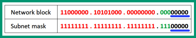
Figure 5.18 – Remaining host bits
To determine whether each of the eight new subnets will be able to support the largest network within the organization of 28 hosts, we need to calculate the total number of IPv4 addresses per network using the following formula:
Total IPv4 addresses = 2H
= 25
= 2 x 2 x 2 x 2 x 2
= 32
Using five host bits within any of the eight new networks will provide a total of 32 IPv4 addresses, inclusive of the network ID and broadcast addresses for each network. However, since the network ID and broadcast addresses can’t be assigned to devices within an IPv4 network, we need to exclude them. The following formula is used to calculate the number of usable (assignable) IPv4 addresses per network:
Usable IPv4 address = 2H – 2
= 25 – 2
= (2 x 2 x 2 x 2 x 2) – 2
= 30
Based on the results, each of the eight new subnets will contain 30 usable IPv4 addresses that can be assigned to devices. As a result, we have found a workable solution of using a Class C address block and using mathematical calculations to determine whether it’s suitable for the organization. Since this solution is workable, we are converting three host bits into network bits, and a new subnet mask is created for each of the new subnets, so they will be using 255.255.255.224 with a network prefix of /27.
Important note
When performing subnetting, the original address block is broken down into smaller networks called subnetworks (subnets), and the subnet mask changes to support each new subnet.
The following are important guidelines when creating new subnetworks:
- Ensure you do not modify/change the bits within the network portion of the IP address
- Ensure you do not modify/change the new host portion of the IP address
- Ensure you only modify the new network bits as these are used to create the new subnetworks
By changing the new network bits from 0s to 1s within the IP address, we can create all the possibilities for new network IDs. The following are the calculations for creating the eight new subnets:

Figure 5.19 – New subnets
As we can see, the first three bits within the 4th octet are the new network bits, and changing each bit value from 0 to 1 creates a new subnetwork. These are the network IDs for the new eight subnetworks with their new network prefix. Therefore, the last five bits within the 4th octet are the new host bits for each new subnet.
Tip
Since each subnet is equal in terms of total IP addresses, using the 2H formula will help you quickly determine the incremental value between the subnet and determine the network IDs.
Now that you’ve calculated the network IDs for each of the eight new subnets, next, you will discover how to calculate the IP address ranges for each subnet.
Step 3 – assigning subnets to each network
In this step, you’ll learn how to calculate the IP address ranges for each new subnet by determining the network ID, the first and last usable addresses, and the broadcast address per subnet.
To ensure your calculations are done efficiently, use the following guidelines:
- To determine the first usable IP address within a subnet, use the network ID + 1 formula. In binary notation, the first bit from the left is set to 1.
- To calculate the broadcast address within a subnet, use the Next network ID – 1 formula. In binary notation, it’s when all the host bits are 1s within the address.
- To calculate the last usable IP address within a subnet, use the Broadcast Address – 1 formula. In binary notation, it’s where all the host bits are 1s except the bit to the farthest right.
Using these guidelines, let’s calculate the network range of the first subnet and assign it to the main office LAN network:

Figure 5.20 – Subnet 1 network range
As shown in the preceding table, the network ID is determined when all the host bits are 0s within the address. While the first usable IPv4 address is when the first bit from the right is only 1, the last usable address is when all the host bits are 1s except the bit to the farthest right of the address, and the broadcast address is when all the hosts are 1s.
Next, applying the same mathematical technique, let’s determine the network range of the next subnet that will be assigned to the Branch A LAN network:

Figure 5.21 – Subnet 2 network range
Next, repeating our technique, let’s calculate the network range of the third subnet that will be assigned to the Branch B LAN network:

Figure 5.22 – Subnet 3 network range
Next, let’s determine the network range of the fourth subnet that will be assigned to the Branch C LAN network:
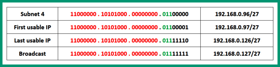
Figure 5.23 – Subnet 4 network range
So far, we can successfully assign the first four subnets to each LAN for each office location of the organization. However, three WAN networks are used to interconnect each branch router to the main office router. These WAN links are point-to-point connections that require only two IP addresses per WAN connection:
- WAN 1: Main office router to Branch A router – only two IP addresses are needed
- WAN 2: Main office router to Branch B router – only two IP addresses are needed
- WAN 3: Main office router to Branch C router – only two IP addresses are needed
If we were to assign the remaining subnets to any of the WAN networks, there will be a lot of wastage of IPv4 addresses. Since each subnet has 30 usable IPv4 addresses and each WAN link requires only two IP addresses, there will be a wastage of 28 IPv4 addresses per WAN link.
To further avoid wastage of IPv4 addresses within our new subnets while being able to assign IPv4 addresses to our WAN networks, we can use a technique known as Variable Length Subnet Masking (VLSM), which allows us to further break down a subnet into smaller subnetworks. Think of it as subnetting a subnet even further to reduce IPv4 address wastage on a network. We can use any of the remaining following subnets for VLSM:
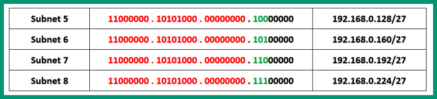
Figure 5.24 – Unallocated networks
The preceding table shows the unallocated subnets that haven’t been assigned to any networks within the organization of our scenario. Since these unallocated subnets are equal in size, we can use any one of these remaining subnets to perform our VLSM technique. To keep everything simple and easy to understand, the following subnets will be documented and reserved for future office locations:
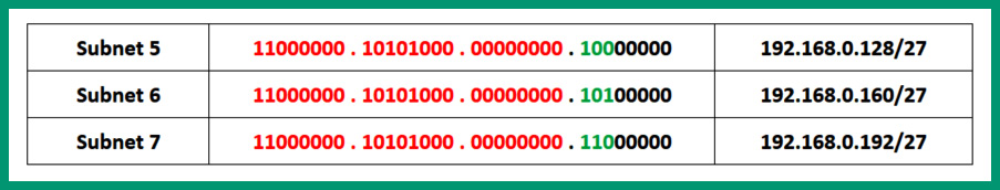
Figure 5.25 – Subnet reservations
The following subnet will be broken down using VLSM to create smaller subnetworks:

Figure 5.26 – Eighth subnet
In the next step, you will learn how to perform VLSM on the eighth subnet to create small subnets to support the WAN links between the remote offices and the main office.
Step 4 – performing Variable-Length Subnet Masking (VLSM)
In this step, you will learn how to further break down a subnet to create smaller IP networks with smaller broadcast domains while efficiently distributing IP addresses with the least wastage. Since each of the three WAN links are point-to-point networks that require only two IP addresses, we can determine the number of host bits needed within an IP address to provide two usable IP addresses.
To calculate the number of usable IP addresses within a network, use the following formula:
Number of usable IPv4 addresses = 2H – 2
As you may recall, H represents the number of host bits within an IP address.
To get started, let’s convert the 192.168.0.224/27 subnet into binary notation to visualize the network and host portions of the address:
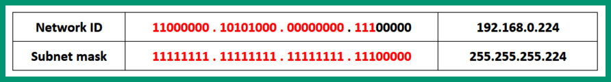
Figure 5.27 – Binary notation
As shown in the preceding table, there are five hosts within the network. If we use one host bit (the 32nd bit) from the 192.168.0.224/27 network ID within our formula, the following will be the result of usable IPv4 addresses:
Number of usable IPv4 addresses = 2H – 2
= 21 – 2
= 2 – 2
= 0
Using one host bit will result in 0 usable IP addresses. Let’s use two host bits (the 31st and 32nd bits) from the same network ID, 192.168.0.224/27, within our formula to determine the number of usable IP addresses:
Number of usable IPv4 addresses = 2H – 2
= 22 – 2
= (2 x 2) – 2
= 4 – 2
= 2
Using two host bits provides two usable addresses. At this point, we have a solution for creating new subnets from the 192.168.0.224/27 network block, which has two usable IP addresses per new subnet. To ensure this solution is workable, the two host bits that we are going to use will remain as host bits – that is, 00 within the address. This leaves us with three remaining bits within the host portion of the 192.168.0.224/27 network block. These remaining bits will be converted into network bits for creating the new subnets.
The following formula provides the number of new subnets when converting three host bits into network bits:
Number of networks = 2N
= 23
= 2 x 2 x 2
= 8
Converting three host bits into network bits will provide us with a total of eight new subnets from the 192.168.0.224/27 network block; each subnet will contain a total of four IPv4 addresses inclusive of two usable addresses. By creating eight new with two usable addresses, we can assign three of the eight new subnets to the existing WAN links; the remaining subnet can be documented as a reservation for the future growth of the organization.
The following table shows the effects of converting three host bits within the subnet mask into network bits to create eight new subnets from the 192.168.0.224/27 network block:

Figure 5.28 – Creating new network bits
As we can see, converting three host bits into network bits creates a new subnet mask of 255.255.255.252 or a network prefix of /30 for the eight new subnets from the 192.168.0.224 network block. Additionally, notice that two host bits are remaining within the host portion of the addresses. These host bits will ensure there are two usable addresses within each of the new subnets.
Before getting started with VLSM, please use the following guidelines to prevent any miscalculations of new subnets:
- Do not change or modify the original network bits within the network portion of the address
- Do not change or modify the new host bits within the host portion of the address
- Only change or modify the new network bits within the address
The following table shows all the possibilities of modifying the new network bits from the address by changing the 0s to 1s, creating eight new subnets from the 192.168.0.224 network block:

Figure 5.29 – VLSM networks
The preceding table shows the eight new networks that were created from the 192.168.0.224 network block. Each new subnet has a network prefix of /30 to support a total of four IPv4 addresses, inclusive of two usable addresses for the WAN point-to-point links within the organization.
The following are the calculations used to determine the network range of the first subnet that will be assigned between the main office router and Branch A router:
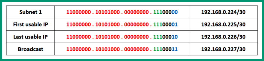
Figure 5.30 – WAN 1 allocation
The following are the calculations used to determine the network range of the second subnet that will be assigned between the main office router and Branch B router:
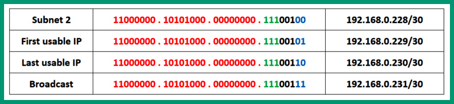
Figure 5.31 – WAN 2 allocation
The following are the calculations used to determine the network range of the third subnet that will be assigned between the main office router and Branch C router:

Figure 5.32 – WAN 3 allocation
Now that we’ve allocated the first three subnets to the WAN links within the organization, the following five subnets will be documented and reserved within the company to support future growth:

Figure 5.33 – Reserved WAN subnets
These remaining WAN subnets will be needed in the future when the organization is growing and creating new remote offices. Planning for the future growth of an organization is important when designing an IP address scheme. Network professionals should consider the growth of each department within an organization, the growth of branch offices, and the entire organization as well. Using statistical data from human resources can assist in how the organization has grown within the past 5-10 years. Using this information can help network professionals determine an appropriate address class and how to create their subnetworks to support their company.
Lastly, the following table shows the allocation for networks with a /27 network prefix:

Figure 5.34 – Subnets for LANs
The following table shows the allocation for networks that use the /30 network prefix:

Figure 5.35 – Subnets for WANs
Having completed this section, you have gained the hands-on skills to perform subnetting and VLSM as a network professional.
Summary
In this chapter, you learned about the importance of subnetting and the role it plays within the networking industry and the internet. You have acquired the skills to identify the network and host portions of addresses and determine the network prefix of an address. Furthermore, you have gained the hands-on skills needed to perform subnetting on a network address block to create subnetworks.
I hope this chapter has been informative for you and is helpful in your journey toward learning networking and becoming a network professional. In the next chapter, Chapter 6, Exploring Network Protocols and Services, you will explore various network protocols and traffic types.
Questions
The following is a short list of review questions to help reinforce your learning and help you identify areas that may require some improvement.
- Which of the following is a valid host of the 172.16.150.0/23 network?
A. 172.16.160.56
B. 172.16.150.256
C. 172.16.150.56
D. 172.17.150.1
- Which of the following is the first usable address of a network that has an end device with the 192.168.46.234/26 address?
A. 192.168.46.192
B. 192.168.46.191
C. 192.168.46.187
D. 192.168.46.197
- Which of the following subnets does the host 10.45.67.32/19 address belong to?
A. 10.45.97.0
B. 10.45.64.0
C. 10.45.63.0
D. 10.45.67.128
- Which of the following is the broadcast address for the 172.30.56.48/28 network?
A. 172.30.56.61
B. 172.30.56.62
C. 172.30.56.63
D. 172.30.56.64
- Which of the following is a valid host of the 192.16.10.0/20 network?
A. 192.16.15.100
B. 192.16.16.100
C. 192.15.15.100
D. 192.16.16.2
- Which of the following is the first usable address of a network that has an end device with the 172.10.146.24/18 address?
A. 172.10.148.1
B. 172.10.146.1
C. 172.10.148.1
D. 172.10.128.1
- Which of the following subnets does the host 100.5.67.36/29 address belong to?
A. 100.5.66.32
B. 100.5.66.64
C. 100.5.67.32
D. 100.5.67.0
- Which of the following is the broadcast address for the 12.39.6.68/28 network?
A. 12.38.6.79
B. 12.39.7.79
C. 12.39.8.79
D. 12.39.6.78
- Which of the following is a valid host of the 12.100.90.0/23 network?
A. 12.100.91.24
B. 12.100.91.257
C. 12.10.91.24
D. 12.10.93.24
- Which of the following is the first usable address of a network that has an end device with the 10.168.46.234/9 address?
A. 10.12.0.1
B. 10.167.0.1
C. 10.128.0.1
D. 10.12.0.1
Further reading
To learn more about the topics that were covered in this chapter, check out the following links:
- What Is Network Segmentation?: https://www.comptia.org/blog/security-awareness-training-network-segmentation
- IP Addressing and Subnetting: https://www.cisco.com/c/en/us/support/docs/ip/routing-information-protocol-rip/13788-3.html
- Host and Subnet Quantities: https://www.cisco.com/c/en/us/support/docs/ip/routing-information-protocol-rip/13790-8.html