
Chapter 21
Data Center Architecture and Cloud Concepts
If you didn't just skip toward the end of this book, you've trekked through enough material to know that, without a doubt, the task of designing, implementing, and maintaining a state-of-the-art network doesn't happen magically. Ending up with a great network requires some really solid planning before you buy even one device for it. And planning includes thoroughly analyzing your design for potential flaws and optimizing configurations everywhere you can to maximize the network's future throughput and performance. If you blow it in this phase, trust me—you'll pay dearly later in bottom-line costs and countless hours consumed troubleshooting and putting out the fires of faulty design.
Start planning by creating an outline that precisely delimits all goals and business requirements for the network, and refer back to it often to ensure that you don't deliver a network that falls short of your client's present needs or fails to offer the scalability to grow with those needs. Drawing out your design and jotting down all the relevant information really helps in spotting weaknesses and faults. If you have a team, make sure everyone on it gets to examine the design and evaluate it, and keep that network plan active throughout the installation phase. Hang on to this plan even after implementation has been completed because having it is like having the keys to the kingdom; it will enable you to efficiently troubleshoot any issues that could arise after everything is in place and up and running.
High-quality documentation should include a baseline for network performance because you and your client need to know what “normal” looks like in order to detect problems before they develop into disasters. Don't forget to verify that the network conforms to all internal and external regulations and that you've developed and itemized solid management procedures and security policies for future network administrators to refer to and follow.
I'll begin this chapter by going over fundamentals like plans, diagrams, baselines, rules, and regulations and then move on to cover critical hardware and software utilities you should have in your problem resolution arsenal, like packet sniffers, throughput testers, connectivity packages, and even different types of event logs on your servers. And because even the best designs usually need a little boost after they've been up and running for a while, I'll wrap things up by telling you about some cool ways you can tweak things to really jack up a network's performance, optimize its data throughput, and, well, keep it all humming along as efficiently and smoothly as possible.
Data Center Network Architectures
Modern data center networking divides the task up into three sections called tiers or layers, as shown in Figure 21.1. Each layer has a specific function in the data center for various connectivity types. In addition to the traditional data center architectures, I will show you some of the newer designs that are often called the fabric or spine-leaf.
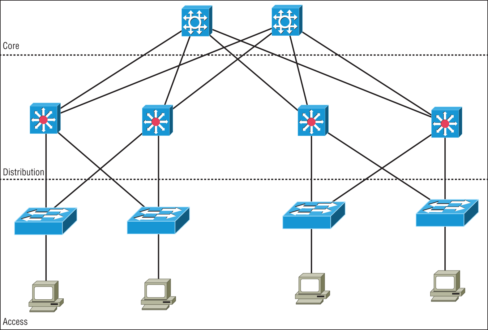
FIGURE 21.1 Data center three-tier architecture
Access/Edge Layer
Starting at the outside of the network and working toward the middle is the access layer, which is also referred to as the edge. This is where all of the devices in the data center attach to the network. This could include servers and Ethernet-based storage devices. The access layer consists of a large number of switches that are often installed at the top or end of each rack to keep cable runs to the servers at a minimum to reduce cable clutter.
Access Ethernet switches are usually fixed port configurations ranging from 12 to 48 ports and are layer two/VLAN based in the most common architecture. The Spanning Tree Protocol (STP) is implemented to prevent network loops from occurring. Access switches will feature high-speed uplink ports from 1G all the way up to 100G to connect to the rest of the network at the distribution layer.
In today's data centers, much of the data flows are between servers, sometimes called East-West traffic. Since the data often stays inside the data center and is server to server, the access switches provide high-speed, low-latency local interconnections between the servers.
Distribution Layer
The middle tier of the three-tier network is called the distribution or aggregation layer. The task of the distribution layer is to provide redundant interconnections for all of the access switches, connect to the core switches, and implement security and access control and layer 3 routing. Distribution switches are chassis-based with modules for different connection types, redundant power, fans, and control logic. Also, the distribution layer provides network redundancy; if one switch should fail, the other can assume the traffic load without incurring any downtime. So, as you would guess, there will always be at least two distribution switches and sometimes more depending on the size of the network. All of the access switches have high-speed uplinks to each of the distribution switches and the distribution switches are all interconnected.
Core Layer
The core layer provides the interconnectivity between all of the network pods in the data center. These are highly redundant and very high-speed interconnection devices. The core switches are usually high-end chassis-based switches with full hardware redundancy as is used in the distribution layer. All of the distribution switches will be connected to redundant core switches to exchange traffic. The core devices can be either routers or switches, depending on the architecture of the data center backbone network, but they do not implement advanced features such as security since the job of the core is to exchange traffic with minimal delays.
Software-Defined Networking
As modern networks grew in complexity and size, it has become increasingly difficult to configure, manage, and control them. There has traditionally been no centralized control plane, which means to make even the simplest of changes often many switches had to be individually accessed and configured.
With the introduction of software-defined networking, a centralized controller is implemented and all of the networking devices are managed as a complete set and not individually. This greatly reduces the amount of configuration tasks required to make changes to the network and allows the network to be monitored as a single entity instead of many different independent switches and routers.
Application Layer
The application layer contains the standard network applications or functions like intrusion detection/prevention appliances, load balancers, proxy servers, and firewalls that either explicitly and programmatically communicate their desired network behavior or provide their network requirements to the SDN controller.
Control Layer
The control layer, or management plane, translates the instructions or requirements received from the application layer devices, proceeds the requests, and configures the SDN-controlled network devices in the infrastructure layer.
The control layer also pushes to the application layer devices information received from the networking devices.
The SDN Controller sits in the control layer and processes configuration, monitoring, and any other application-specific information between the application layer and infrastructure layer.
The northbound interface is the connection between the controller and applications, while the southbound interface is the connection between the controller and the infrastructure layer.
Infrastructure Layer
The infrastructure layer, or forwarding plane, consists of the actual networking hardware devices that control the forwarding and processing for the network. This is where the -/leaf switches sit and are connected to the SDN controller for configuration and operation commands.
The spine and leaf switches handle packet forwarding based on the rules provided by the SDN controller.
The infrastructure layer is also responsible for collecting network health and statistics such as traffic, topology, usage, logging, errors, and analytics and sending this information to the control layer.
Management Plane
SDN network architectures are often broken into three main functions: the management plane, the control plane, and the forwarding plane.
The management plane is the configuration interface to the SDN controllers and is used to configure and manage the network. The protocols commonly used are HTTP/HTTPS for web browser access, Secure Shell (SSH) for command-line programs, and application programming interfaces (APIs) for machine-to-machine communications.
The management plane is responsible for monitoring, configuring, and maintaining the data center switch fabric. It is used to configure the forwarding plane. It is considered to be a subset of the control plane.
The control plane includes the routing and switching functions and protocols used to select the patch used to send the packets or frames as well as a basic configuration of the network.
The data plane refers to all the functions and processes that forward packets/frames from one interface to another; it moves the bits across the fabric.
Spine-Leaf–Based Two-Tier Networks
Data center networks are evolving into two-tier fabric-based networks that are also referred to as spine-leaf architecture as is shown in Figure 21.2.
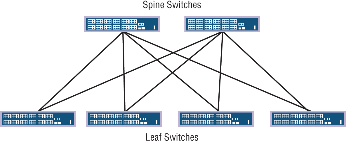
FIGURE 21.2 Spine-leaf fabric architecture
Spine switches have extremely high-throughput, low-latency, and port-dense switches that have direct high-speed (10, 25, 40 to 100 Gbps) connections to each leaf switch.
Leaf switches are very similar to traditional top-of-rack access switches in that they are often 24- or 48-port 1, 10, 25, or 40 Gbps access layer connections but have the increased capability of either 40, 100, or higher uplinks to each spine switch.
The two-tier architecture offers the following advantages over the traditional three-tier designs:
- Resiliency: Each leaf switch connects to every spine switch, the spanning tree is not needed, and due to layer 3 routing protocols being used, now every uplink can be used concurrently.
- Latency: There is a maximum of two hops for any East-West packet flow over very high-speed links, so ultra-low latency is standard.
- Performance: True active-active uplinks enable traffic to flow over the least congested high-speed links available.
- Scalability: You can increase leaf switch quantity to desired port capacity and add spine switches as needed for uplinks.
- Adaptability: Multiple spine-leaf networks across a multitenant or private cloud design are often managed from software-defined networking controllers.
Top-of-Rack Switching
Top-of-rack switching refers to the access switches in the data center network. The objective is to place the switch at the top of each rack and cable the devices in the rack to the local switch as shown in Figure 21.3. The top-of-rack (TOR) switch connects to the distribution or spine switches with high-speed links such as 10G, 25G, 40G, or 100G Ethernet interfaces.
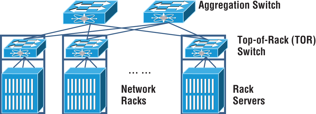
FIGURE 21.3 Top-of-rack switching
The advantage of using a top-of-rack topology is that lower-cost copper or coax cabling is used and the cable density is restricted inside each rack.
If the cable density is low, then an end-of-row approach is used where the switch is placed at the end of a row of data center cabinets and all devises in the row cable to the end-of-row switch.
Backbone
The data center backbone switches or routers are either a spine switch or core switches depending on your topology. Backbone switches have very high-speed interfaces and are used to interconnect the access or leaf switches. The backbone does not have any direct server connections, only connections to other network devices. It is common for backbone switches to have 10G and higher interface speeds and to be highly redundant.
Traffic Flows
In a data center there are server-to-server communications and also communications to the outside word. These are called North-South and East-West.
Today, there is a substantial amount of traffic between devices in the data center that is often much greater than the flows into and out of the network. It is important to understand your network and make sure it is designed properly so there are no congestion points that could cause slowdowns.
North-South
North-South traffic typically indicates data flow that either enters or leaves the data center from/to a system physically residing outside the data center, such as user to server.
North-South traffic (or data flow) is the traffic into and out of a data center. as shown in Figure 21.4.
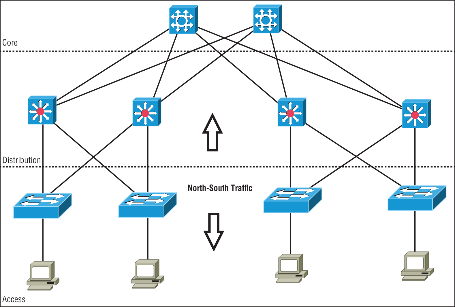
FIGURE 21.4 North-South data flow
Southbound traffic is data entering the data center from the outside, such as from the Internet or a private network. Usually the border network consists of a router and firewall to define the border of the data center network with the outside world.
Data leaving the data center is referred to as northbound traffic.
East-West
East-West traffic describes the traffic flow inside a data center and refers to the data sent and received between devices, as shown in Figure 21.5.
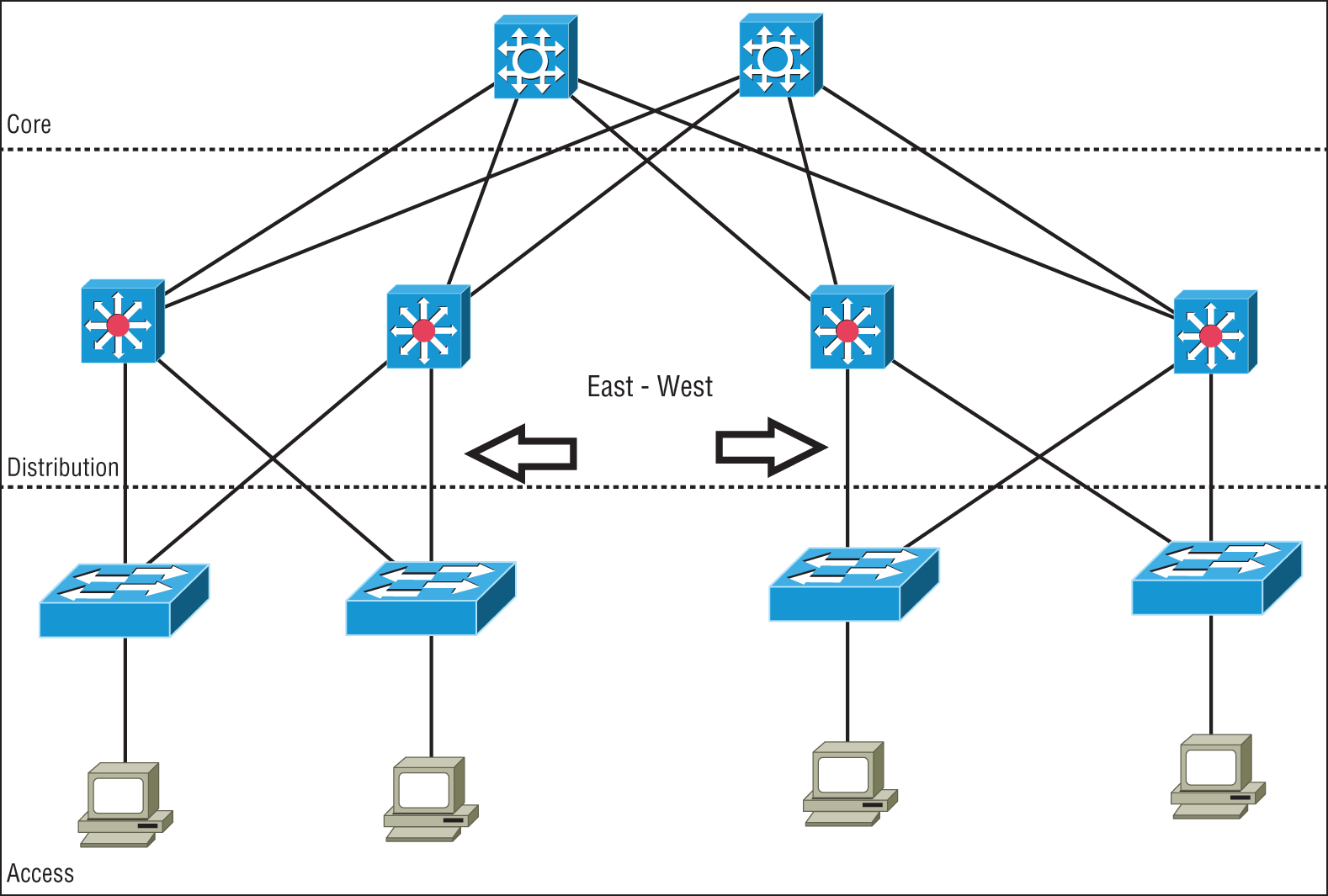
FIGURE 21.5 East-West data flow in a data center
With modern decentralized application designs, virtualizations, private clouds, converged and hyper-converged infrastructures, East-West traffic volume is usually greater than the North-South traffic into and out of the data center.
Many applications, containers, servers, and virtualized networking devices exchange data between each other inside the data center. This East-West traffic benefits from high-speed interconnections for low-latency transfers of large amounts of data that the spine-leaf architecture provides.
Branch Office vs. On-premises Data Center vs. Colocation
When deciding where to place a data center, there are many variables that must be taken into account. These factors can often be in conflict with each other when deciding how to deploy your compute and storage resources. Do you place them nearest to the end users? Do you build and manage your own data center? Maybe leasing space would be a better solution?
A branch office can be a large office campus or a remote retail or distribution center. The common factor is that you put the data center nearest the people who access and rely on the services they provide. This can increase uptime because there are no remote links that can go down. It can also add to the fragility unless redundant and backup systems are put in place, which can drive up costs due to the increased number of data centers rather than a larger, centralized data center. Branch office data centers often do not have local technical expertise, and it is generally more difficult to monitor and maintain a large number of small data centers over a more centralized approach. With hyper-converged architectures, it is feasible to place some of your compute and storage resources at the remote locations for backup and local processing while still maintaining a central data center.
The traditional approach has been to maintain one or more private on-premises data centers. This puts everything under your control. A company can place staff and security in the data center and handle all of the operations themselves. It is recommended that a backup data center be deployed that is some distance away in case of an outage at the primary data center due to man-made or natural disasters. With a distance of several hundred miles separating the primary and backup data centers, a hurricane, for example, would not affect the backup if the primary data center fails.
Many companies choose to use the services of co-located (colo) data centers. Specialized co-location data center providers build, manage, and maintain high-end data center facilities and lease space. This allows you to access high-end services such as redundant power, cooling, and telco circuits for less cost than if you were to implement these in an in-house data center.
Cloud Computing and Its Effect on the Enterprise Network
Cloud computing is by far one of the hottest topics in today's IT world. Basically, cloud computing can provide virtualized processing, storage, and computing resources to users remotely, making the resources transparently available regardless of the user connection. To put it simply, some people just refer to the cloud as “someone else's hard drive.” This is true, of course, but the cloud is much more than just storage.
The history of the consolidation and virtualization of our servers tells us that this has become the de facto way of implementing servers because of basic resource efficiency. Two physical servers will use twice the amount of electricity as one server, but through virtualization, one physical server can host two virtual machines, hence the main thrust toward virtualization. With it, network components can simply be shared more efficiently.
Users connecting to a cloud provider's network, whether it be for storage or applications, really don't care about the underlying infrastructure because, as computing becomes a service rather than a product, it's then considered an on-demand resource, as shown in Figure 21.6.
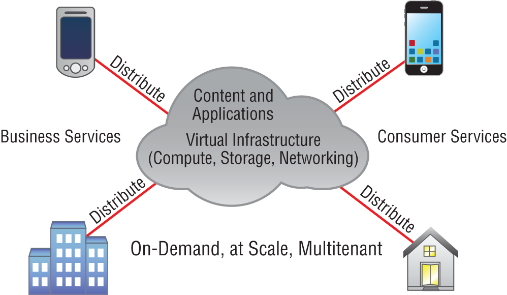
FIGURE 21.6 Cloud computing is on demand.
Centralization/consolidation of resources, automation of services, virtualization, and standardization are just a few of the big benefits cloud services offer. Let's take a look at Figure 21.7.
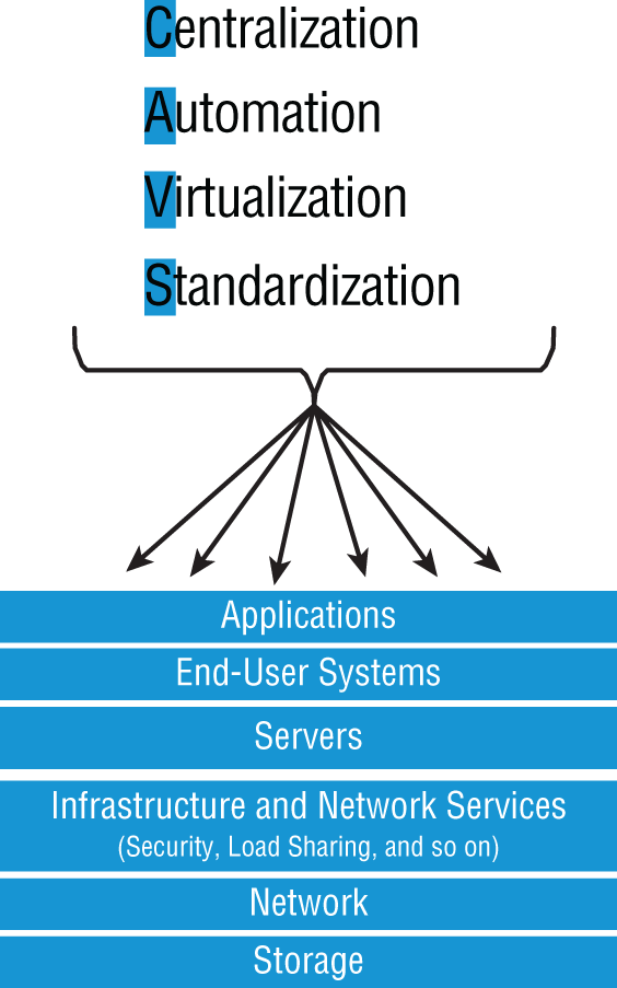
FIGURE 21.7 Advantages of cloud computing
Cloud computing has several advantages over the traditional use of computer resources. The following are the advantages to the provider and to the cloud user.
The advantages to a cloud service builder or provider are:
- Cost reduction, standardization, and automation
- High utilization through virtualized, shared resources
- Easier administration
- Fall-in-place operations model
The advantages to cloud users are:
- On-demand, self-service resource provisioning
- Fast deployment cycles
- Cost effectiveness
- Centralized appearance of resources
- Highly available, horizontally scaled application architectures
- No local backups
Having centralized resources is critical for today's workforce. For example, if you have your documents stored locally on your laptop and your laptop gets stolen, you've pretty much lost everything unless you're doing constant local backups. That is so 2005!
After I lost my laptop and all the files for the book I was writing at the time, I swore (yes, I did that too) to never have my files stored locally again. I started using only Google Drive, OneDrive, and Dropbox for all my files, and they became my best backup friends. If I lose my laptop now, I just need to log in from any computer from anywhere to my service provider's logical drives and presto, I have all my files again. This is clearly a simple example of using cloud computing, specifically SaaS (which is discussed next), and it's wonderful!
So cloud computing provides for the sharing of resources, lower cost operations passed to the cloud consumer, computing scaling, and the ability to dynamically add new servers without going through the procurement and deployment process.
Service Models
Cloud providers can offer you different available resources based on your needs and budget. You can choose just a vitalized network platform or go all in with the network, OS, and application resources.
Figure 21.8 shows the three service models available, depending on the type of service you choose to get from a cloud.
You can see that Infrastructure as a Service (IaaS) allows the customer to manage most of the network, whereas Software as a Service (SaaS) doesn't allow any management by the customer, and Platform as a Service (PaaS) is somewhere in the middle of the two. Clearly, choices can be cost-driven, so the most important thing is that the customer pays only for the services or infrastructure they use.
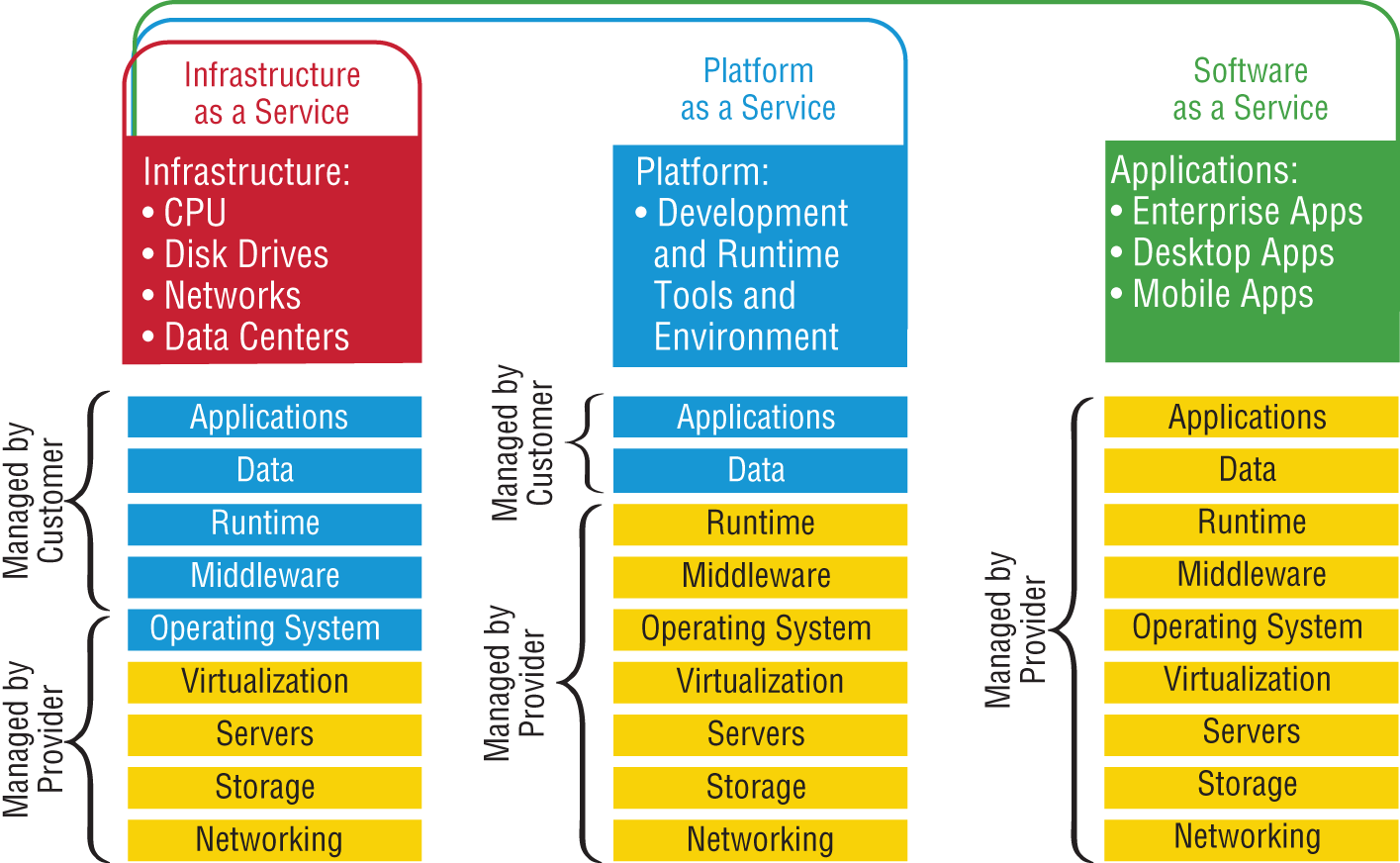
FIGURE 21.8 Cloud computing services
Let's take a look at each service:
- IaaS: Provides only the network. Delivers computer infrastructure—a platform virtualization environment—where the customer has the most control and management capability.
- PaaS: Provides the operating system and the network. Delivers a computing platform and solution stack, allowing customers to develop, run, and manage applications without the complexity of building and maintaining the infrastructure typically associated with developing and launching an application. An example is Windows Azure.
- SaaS: Provides the required software, operating system, and network. SaaS consists of common application software such as databases, web servers, and email software that's hosted by the SaaS vendor. The customer accesses this software over the Internet. Instead of having users install software on their computers or servers, the SaaS vendor owns the software and runs it on computers in its data center. Microsoft Office 365 and many Amazon Web Services (AWS) offerings are perfect examples of SaaS.
- DaaS: Provides the desktop and other resources. DaaS hosts the desktop operating system, such as Windows or Linux, plus the storage, infrastructure, and network resources inside the data center. A data stream of the desktop is accessed from the user's remote device, usually via a web browser or a small application residing on the user's computer, tablet, or phone. This allows all applications, data, and security standards to be hosted inside the data center for centralized management.
So depending on your business requirements and budget, cloud service providers market a very broad offering of cloud computing products, from highly specialized offerings to a large selection of services.
What's nice here is that you're offered a fixed price for each service that you use, which allows you to easily budget wisely for the future. It's true—at first, you'll have to spend a little cash on staff training, but with automation you can do more with less staff because administration will be easier and less complex. All of this works to free up the company resources to work on new business requirements and allows the company to be more agile and innovative in the long run.
Overview of Network Programmability in Enterprise Network
Right now in our current, traditional networks, our router and switch ports are the only devices that are not virtualized. So this is what we're really trying to do here—virtualize our physical ports.
First, understand that our current routers and switches run an operating system, such as Cisco IOS, that provides network functionality. This has worked well for us for 25 years or so, but it is way too cumbersome now to configure, implement, and troubleshoot these autonomous devices in today's large, complicated networks. Before you even get started, you have to understand the business requirements and then push that out to all the devices. This can take weeks or even months since each device is configured, maintained, and monitored separately.
Before we can talk about the new way to network our ports, you need to understand how our current networks forward data, which happens via these two planes:
- Data Plane This plane, also referred to as the forwarding plane, is physically responsible for forwarding frames of packets from its ingress to egress interfaces using protocols managed in the control plane. Here, data is received, the destination interface is looked up, and the forwarding of frames and packets happens, so the data plane relies completely on the control plane to provide solid information.
- Control Plane This plane is responsible for managing and controlling any forwarding table that the data plane uses. For example, routing protocols such as OSPF, EIGRP, RIP, and BGP as well as IPv4 ARP, IPv6 NDP, switch MAC address learning, and STP are all managed by the control plane.
Now that you understand that there are two planes used to forward traffic in our current or legacy network, let's look at the future of networking.
Software-Defined Networking
Traditional networks comprised many discreet devices that were managed and configured individually. Today, SDN controllers are deployed that contain the management plane operations for the complete network.
Now, all of the hardware infrastructure devices are not individually configured by network administrators. All commands and operations are now performed on the SDN controller, which is a computer, or cluster of computers, running specialized applications to monitor and configure the complete network. SDN controllers communicate southbound to the underlying hardware at the infrastructure layer for all control and management operations. There are software portals, or application programming interfaces (APIs), that communicate northbound to other applications that need to monitor and access the data center network fabric. The northbound applications could be any number of devices or applications, such as load balancers, ticketing systems, analytics applications, firewalls, authentication servers, or any application that needs to access the network traffic.
The software-defined network allows for very large-scale deployments to be automated and managed much more efficiently than in the past where each device was a stand-alone system.
SDN controllers also allow the fabric to be partitioned into virtual private clouds that different entities or companies can utilize and still be separated from the other networks running on the same platform.
Application Programming Interfaces (APIs)
If you have worked on any enterprise Wi-Fi installations in the past decade, you would have designed your physical network and then configured a type of network controller that managed all the wireless APs in the network. It's hard to imagine that anyone would install a wireless network today without some type of controller in an enterprise network, where the access points (APs) receive their directions from the controller on how to manage the wireless frames and the APs have no operating system or brains to make many decisions on their own.
The same is now true for our physical router and switch ports, and it's precisely this centralized management of network frames and packets that software-defined networking (SDN) provides to us.
SDN removes the control plane intelligence from the network devices by having a central controller manage the network instead of having a full operating system (Cisco IOS, for example) on the devices. In turn, the controller manages the network by separating the control and data (forwarding) planes, which automates configuration and the remediation of all devices.
So instead of the network devices each having individual control planes, we now have a centralized control plane, which consolidates all network operations in the SDN controller. APIs allow for applications to control and configure the network without human intervention. The APIs are another type of configuration interface just like the CLI, SNMP, or GUI interfaces, which facilitate machine-to-machine operations.
The SDN architecture slightly differs from the architecture of traditional networks by adding a third layer, the application plane, as described here and shown in Figure 21.9:
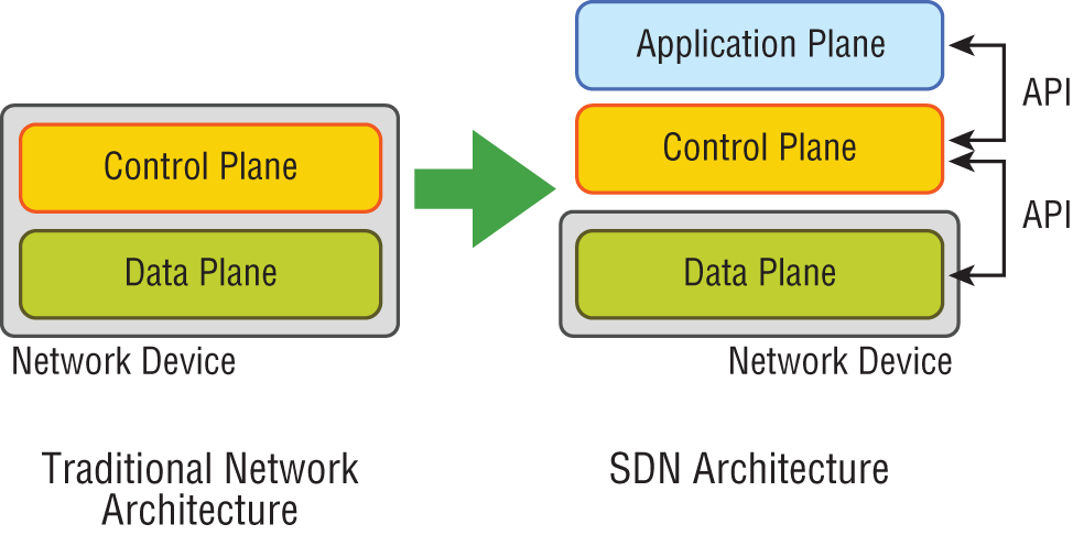
FIGURE 21.9 The SDN architecture
- Data (or Forwarding) Plane Contains network elements, meaning any physical or virtual device that deals with data traffic.
- Control Plane Usually a software solution, the SDN controllers reside here to provide centralized control of the router and switches that populate the data plane, removing the control plane from individual devices.
- Application Plane This new layer contains the applications that communicate their network requirements toward the controller using APIs.
SDN is pretty cool because your applications tell the network what to do based on business needs instead of you having to do it. Then the controller uses the APIs to pass instructions on to your routers, switches, or other network gear. So instead of taking weeks or months to push out a business requirement, the solution now only takes minutes.
There are two sets of APIs that SDN uses and they are very different. As you already know, the SDN controller uses APIs to communicate with both the application and data plane. Communication with the data plane is defined with southbound interfaces, while services are offered to the application plane using the northbound interface. Let's take a deeper look at this oh-so-vital CCNA objective.
Southbound APIs
Logical southbound interface (SBI) APIs (or device-to-control-plane interfaces) are used for communication between the controllers and network devices. They allow the two devices to communicate so that the controller can program the data plane forwarding tables of your routers and switches. SBIs are shown in Figure 21.10.
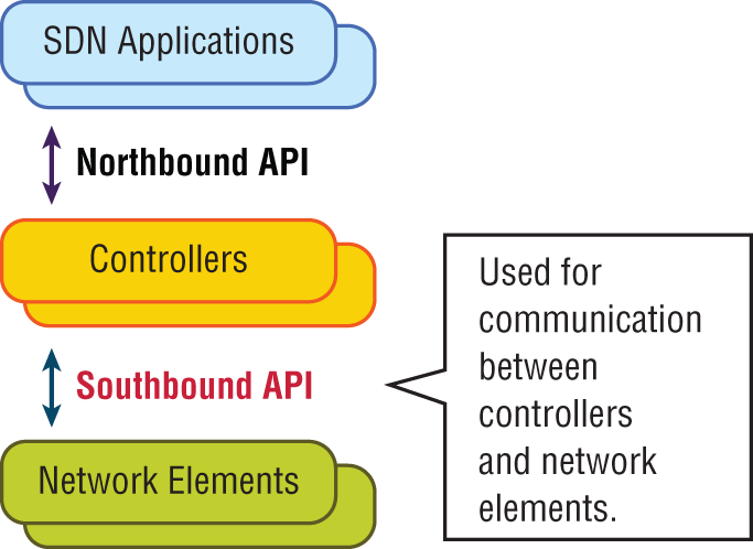
FIGURE 21.10 Southbound interfaces
Since all the network drawings had the network gear below the controller, the APIs that talked to the devices became known as southbound, meaning, “out the southbound interface of the controller.” And don't forget that with SDN, the term interface is no longer referring to a physical interface!
Unlike northbound APIs, southbound APIs have many standards, and you absolutely must know them well for the objectives. Let's talk about them now:
- OpenFlow Describes an industry-standard API, which the ONF (
opennetworking.org) defines. It configures white label switches, meaning that they are nonproprietary, and as a result defines the flow path through the network. All the configuration is done through NETCONF. - NETCONF Although not all devices support NETCONF yet, what this provides is a network management protocol standardized by the IETF. Using RPC, you can use XML to install, manipulate, and delete the configurations of network devices.
- onePK A Cisco proprietary SBI that allows you to inspect or modify the network element configuration without hardware upgrades. This makes life easier for developers by providing software development kits for Java, C, and Python.
- OpFlex The name of the southbound API in the Cisco ACI world is OpFlex, an open-standard, distributed control system. Understand that OpenFlow first sends detailed and complex instructions to the control plane of the network elements in order to implement a new application policy—something called an imperative SDN model. On the other hand, OpFlex uses a declarative SDN model because the controller, which Cisco calls the APIC, sends a more abstract, “summary policy” to the network elements. The summary policy makes the controller believe that the network elements will implement the required changes using their own control planes, since the devices will use a partially centralized control plane.
Northbound APIs
To communicate from the SDN controller and the applications running over the network, you'll use northbound interfaces (NBIs), shown in Figure 21.11.
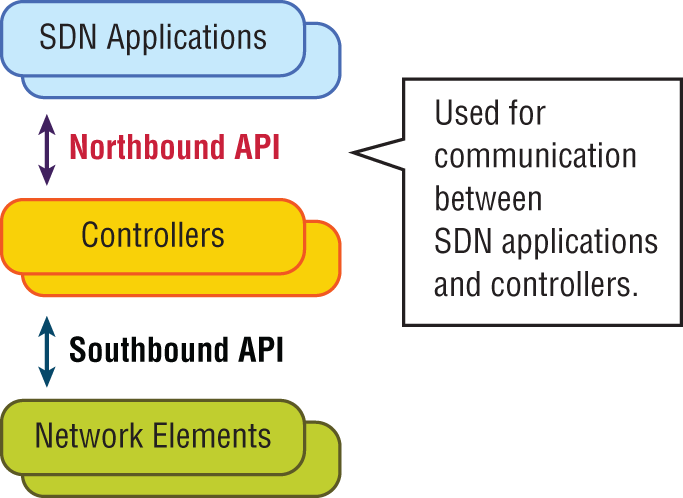
FIGURE 21.11 Northbound interfaces
By setting up a framework that allows the application to demand the network setup with the configuration that it needs, the NBIs allow your applications to manage and control the network. This is priceless for saving time because you no longer need to adjust and tweak your network to get a service or application running correctly.
The NBI applications include a wide variety of automated network services, from network virtualization and dynamic virtual network provisioning to more granular firewall monitoring, user identity management, and access policy control. This allows for cloud orchestration applications that tie together, for server provisioning, storage, and networking that enables a complete rollout of new cloud services in minutes instead of weeks!
Sadly, at the time of this writing, there is no single northbound interface that you can use for communication between the controller and all applications. So instead, you use various and sundry northbound APIs, with each one working only with a specific set of applications.
Most of the time, applications used by NBIs will be on the same system as the APIC controller, so the APIs don't need to send messages over the network since both programs run on the same system. However, if they don't reside on the same system, REST (Representational State Transfer) comes into play; it uses HTTP messages to transfer data over the API for applications that sit on different hosts.
Managing Network Documentation
I'll admit it—creating network documentation is one of my least favorite tasks in network administration. It just isn't as exciting to me as learning about the coolest new technology or tackling and solving a challenging problem. Part of it may be that I think I know my networks well enough—after all, I installed and configured them, so if something comes up, it should be easy to figure it out and fix it, right? And most of the time I can do that, but as networks get bigger and more complex, it gets harder and harder to remember it all. Plus, it's an integral part of the service I provide for my clients to have seriously solid documentation at hand to refer to after I've left the scene and turned their network over to them. So while I'll admit that creating documentation isn't something I get excited about, I know from experience that having it around is critical when problems come up—for myself and for my clients' technicians and administrators, who may not have been part of the installation process and simply aren't familiar with the system.
Using SNMP
In Chapter 6, “Introduction to the Internet Protocol,” I introduced you to Simple Network Management Protocol (SNMP), which is used to gather information from and send settings to devices that are SNMP compatible. Make sure to thoroughly review the differences between versions 1, 2, and 3 that we discussed there! Remember, I told you SNMP gathers data by polling the devices on the network from a management station at fixed or random intervals, requiring them to disclose certain information. This is a big factor that really helps to simplify the process of gathering information about your entire internetwork.
SNMP uses UDP to transfer messages back and forth between the management system and the agents running on the managed devices. Inside the UDP packets (called datagrams) are commands from the management system to the agent. These commands can be used either to get information from the device about its state (SNMP GetRequest) or to make a change in the device's configuration (SetRequest). If a GetRequest command has been sent, the device will respond with an SNMP response. If there's a piece of information that's particularly interesting to an administrator about the device, the administrator can set something called a trap on the device.
So, no whining! Like it or not, we're going to create some solid documentation. But because I'm guessing that you really don't want to redo it, it's a very good idea to keep it safe in at least three forms:
- An electronic copy that you can easily modify after configuration changes
- A hard copy in a binder of some sort, stored in an easily accessible location
- A copy on an external drive to keep in a really safe place (even off site) in case something happens to the other two or the building or part of it burns to the ground
So why the hard copy? Well, what if the computer storing the electronic copy totally crashes and burns at exactly the same time a major crisis develops? Good thing you have that paper documentation on hand for reference! Plus, sometimes you'll be troubleshooting on the run—maybe literally, as in running down the hall to the disaster's origin. Having that binder containing key configuration information on board could save you a lot of time and trouble, and it's also handy for making notes to yourself as you troubleshoot. Also, depending on the size of the intranet and the amount of people staffing the IT department, it might be smart to have several hard copies. Just always make sure they're only checked out by staff who are cleared to have them and that they're all returned to a secure location at the end of each shift. You definitely don't want that information in the wrong hands!
Now that I've hopefully convinced you that you absolutely must have tight documentation, let's take a look at the different types you need on hand so you can learn how to assemble them.
Schematics and Diagrams
Now reading network documentation doesn't exactly compete with racing your friends on jet skis, but it's really not that bad. It's better than eating canned spinach, and sometimes it's actually interesting to check out schematics and diagrams—especially when they describe innovative, elegant designs or when you're hunting down clues needed to solve an intricate problem with an elusive solution. I can't tell you how many times, if something isn't working between point A and point B, a solid diagram of the network that precisely describes what exists between point A and point B has totally saved the day. Another time when these tools come in handy is when you need to extend your network and want a clear picture of how the expanded version will look and work. Will the new addition cause one part of the network to become bogged down while another remains underutilized? You get the idea.
Diagrams can be simple sketches created while brainstorming or troubleshooting on the fly. They can also be highly detailed, refined illustrations created with some of the snappy software packages around today, like Microsoft Visio, SmartDraw, and a host of computer-aided design (CAD) programs. Some of the more complex varieties, especially CAD programs, are super pricey. But whatever tool you use to draw pictures about your networks, they basically fall into these groups:
- Wiring diagrams/schematics
- Physical network diagrams
- Logical network diagrams
- Asset management
- IP address utilization
- Vendor documentation
Wiring Schematics
Wireless is definitely the wave of the future, but for now, even the most extensive wireless networks have a wired backbone they rely on to connect them to the rest of humanity.
That skeleton is made up of cabled physical media like coax, fiber, and twisted-pair. Surprisingly, it is the latter—specifically, unshielded twisted-pair (UTP)—that screams to be represented in a diagram. You'll see why in a minute. To help you follow me, let's review what we learned in Chapter 3, “Networking Connectors and Wiring Standards.” We'll start by checking out Figure 21.12 (a diagram!) that describes the fact that UTP cables use an RJ-45 connector (RJ stands for registered jack).
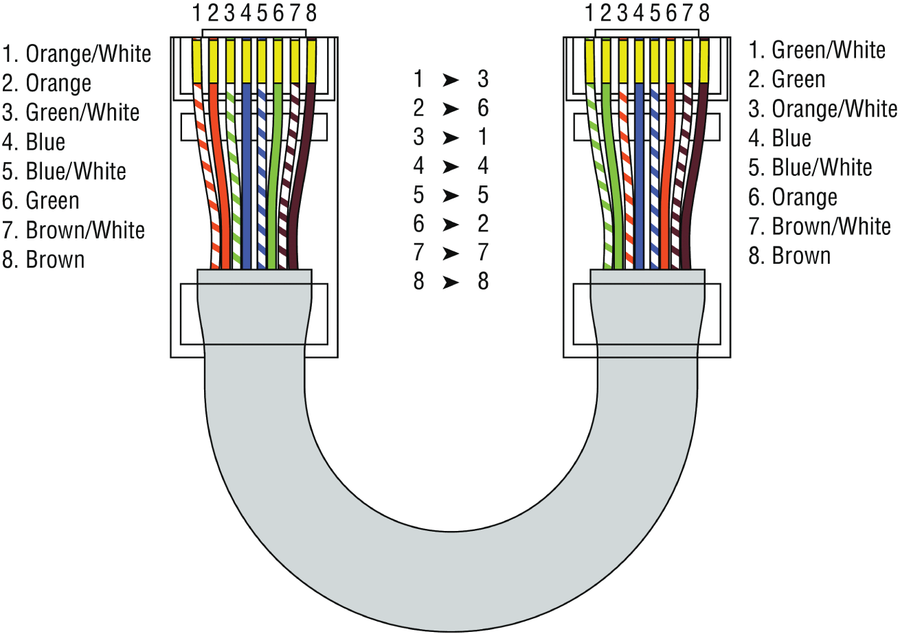
FIGURE 21.12 RJ-45 connector
What we see here is that pin 1 is on the left and pin 8 is on the right, so clearly, within your UTP cable, you need to make sure the right wires get to the right pins. No worries if you got your cables premade from the store, but making them yourself not only saves you a bunch of money, it allows you to customize cable lengths, which is really important!
Table 21.1 matches the colors for the wire associated with each pin, based on the Electronic Industries Association and the Telecommunications Industry Alliance (TIA/EIA) 568B wiring standard.
TABLE 21.1 Standard TIA/EIA 568B wiring
| Pin | Color |
|---|---|
| 1 | Orange/White |
| 2 | Orange |
| 3 | Green/White |
| 4 | Blue |
| 5 | Blue/White |
| 6 | Green |
| 7 | Brown/White |
| 8 | Brown |
Standard drop cables, or patch cables, have the pins in the same order on both connectors. If you're connecting a computer to another computer directly, you should already know that you need a crossover cable that has one connector with flipped wires. Specifically, pins 1 and 3 and pins 2 and 6 get switched to ensure that the send port from one computer's network interface card (NIC) gets attached to the receive port on the other computer's NIC. Crossover cables were also used to connect older routers, switches, and hubs through their uplink ports. Figure 21.13 shows you what this looks like.
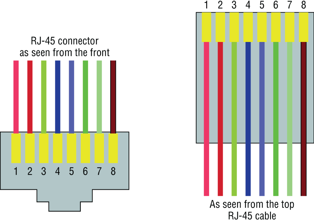
FIGURE 21.13 Two ends of a crossover cable
This is where having a diagram is golden. Let's say you're troubleshooting a network and discover connectivity problems between two hosts. Because you've got the map, you know the cable running between them is brand-new and custom made. This should tell you to go directly to that new cable because it's likely it was poorly made and is therefore causing the snag.
Another reason it's so important to diagram all things wiring is that all wires have to plug into something somewhere, and it's really good to know what and where that is. Whether it's into a hub, a switch, a router, a workstation, or the wall, you positively need to know the who, what, where, when, and how of the way the wiring is attached.
For medium to large networks, devices like switches and routers are rack-mounted and would look something like the switch in Figure 21.14.
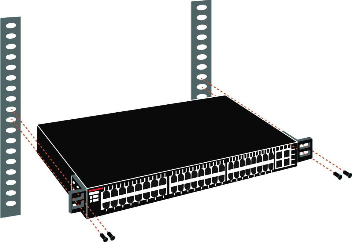
FIGURE 21.14 Rack-mounted switches
Knowing someone's or something's name is important because it helps us differentiate between people and things—especially when communicating with each other. If you want to be specific, you can't just say, “You know that router in the rack?” This is why coming up with a good naming system for all the devices living in your racks will be invaluable for ensuring that your wires don't get crossed.
Okay, I know it probably seems like we're edging over into OCD territory, but stay with me here; in addition to labeling, well, everything so far, you should actually label both ends of your cables too. If something happens (earthquake, tsunami, temper tantrum, even repairs) and more than one cable gets unplugged at the same time, it can get really messy scrambling to reconnect them from memory—fast!
Physical Network Diagrams
Physical diagrams were covered in Chapter 14, “Organizational Documents and Policies”; please refer to it for a detailed explanation.
Logical Network Diagrams
Logical diagrams were also covered in Chapter 14; please refer to that chapter for a detailed explanation.
Asset Management
Asset management involves tracking all network assets like computers, routers, switches, and hubs through their entire life cycles. Most organizations find it beneficial to utilize asset identification numbers to facilitate this process. The ISO has established standards regarding asset management. The ISO 19770 family consists of four major parts:
- 19770-1 is a process-related standard that outlines best practices for IT asset management in an organization.
- 19770-2 is a standard for machine encapsulation (in the form of an XML file known as a SWID tag) of inventory data—allowing users to easily identify what software is deployed on a given device.
- 19770-3 is a standard that provides a schema for machine encapsulation of entitlements and rights associated with software licenses. The records (known as ENTs) will describe all entitlements and rights attendant to a piece of software and the method for measurement of license/entitlement consumption.
- 19770-4 allows for standardized reporting of utilization of resources. This is crucial when considering complex data center license types and for the management of cloud-based software and hardware (Software as a Service, or SaaS, and Infrastructure as a Service, or IaaS).
IP Address Utilization
Documenting the current IP addressing scheme can also be highly beneficial, especially when changes are required. Not only is this really helpful to new technicians, it's very useful when identifying IP addressing issues that can lead to future problems. In many cases IP addresses are configured over a long period of time with no real thought or planning on the macro level.
Current and correct documentation can help administrators identify discontiguous networks (where subnets of a major network are separated by another major network) that can cause routing protocol issues. Proper IP address design can also facilitate summarization, which makes routing tables smaller, speeding the routing process. None of these wise design choices can be made without proper IP address documentation.
Vendor Documentation
Vendor agreements often have beneficial clauses that were negotiated during the purchase process. Many also contain critical details concerning SLAs and deadlines for warranties. These documents need to be organized and stored safely for future reference. Creating a spreadsheet or some other form of tracking documentation that alerts you of upcoming dates of interest can be a huge advantage!
Network Monitoring
Identifying performance issues within the network is only one of the reasons to perform structured monitoring. Security issues also require constant monitoring. In the following sections, we'll look into both types of monitoring and cover some of the best practices and guidelines for success.
Baselines
Baselines were covered in Chapter 14; please refer to that chapter for a detailed explanation.
Processes
When monitoring baselines, there are methods that can be used to enhance the process. In this section we'll look at three particularly helpful processes:
- Log Reviewing While regular log review is always recommended anyway, it can have benefits when monitoring baselines. In some cases you may be able to identify a noncompliant device by the entries in its log or in the logs of infrastructure devices.
- Patch Management Issues In some cases, applying patches, especially device driver updates, can be problematic. Issues can include the device no longer working, loss of some key functionality, or generation of odd error messages.
- Rollback While rollback is a general term that applies to reversing any operation about device drivers, it means to remove the newer driver and go back to using the previous driver. This is typically an available option if the last driver you used is the driver to which you want to roll back.
Onboarding and Offboarding of Mobile Devices
Increasingly, users are doing work on their mobile devices that they once performed on laptops and desktop computers. Moreover, they are demanding that they be able to use their personal devices to work on the company network. This presents a huge security issue for the IT department because they have to secure these devices while simultaneously exercising much less control over them.
The security team must have a way to prevent these personal devices from introducing malware and other security issues to the network. Bring your own device (BYOD) initiatives can be successful if implemented correctly. The key is to implement control over these personal devices that leave the safety of your network and return later after potentially being exposed to environments that are out of your control. One of the methods that has been employed successfully to accomplish this goal is network access control (NAC), covered in the next section.
NAC
Today's network access control (NAC) goes beyond simply authenticating users and devices before they are allowed into the network. Today’s mobile workforce presents challenges that require additional services. These services are called Network Access Control in the Cisco world, and Network Access Protection in the Microsoft world, but the goals of these features are the same: to examine all devices requesting network access for malware, missing security updates, and any other security issues any device could potentially introduce to the network.
In some cases NAC goes beyond simply denying access to systems that fail inspection. NAC can even redirect the failed system to a remediation server, which will then apply patches and updates before allowing the device access to the network. These systems can be especially helpful in supporting a BYOD initiative while still maintaining the security of the network.
Policies, Procedures, and Regulations
It's up to us, individually and corporately, to nail down solid guidelines for the necessary policies and procedures for network installation and operation. Some organizations are bound by regulations that also affect how they conduct their business, and that kind of thing clearly needs to be involved in their choices. But let me take a minute to make sure you understand the difference between policies and procedures.
Policies govern how the network is configured and operated as well as how people are expected to behave on it. They're in place to direct things like how users access resources and which employees and groups get various types of network access and/or privileges. Basically, policies give people guidelines as to what they are expected to do. Procedures are precise descriptions of the appropriate steps to follow in a given situation, such as what to do when an employee is terminated or what to do in the event of a natural disaster. They often dictate precisely how to execute policies as well.
One of the most important aspects of any policy or procedure is that it's given high-level management support. This is because neither will be very effective if there aren't any consequences for not following the rules!
Policies
I talked extensively about security policies in Chapter 16, “Common Security Concepts,” so if you're drawing a blank, you can go back there for details. Here's a summary list of factors that most policies cover:
- Security Policies These are policies applied to users to help maintain security in the network:
- Clean-desk policies: These policies are designed to prevent users from leaving sensitive documents on unattended desks.
- Network access (who, what, and how): These policies control which users can access which portions of the network. They should be designed around job responsibilities.
- Acceptable-use policies (AUPs): These policies should be as comprehensive as possible and should outline every action that is allowed in addition to those that are not allowed. They should also specify which devices are allowed, which websites are allowed, and the proper use of company equipment.
- Consent to monitoring: These policies are designed to constantly remind users that their activities are subject to monitoring as they are using company equipment and as such they should have no expectation of privacy.
- Privileged user agreement: Whenever a user is given some right normally possessed by the administrator, they obtain a privileged user account. In this agreement, they agree to use these rights responsibly.
- Password policy: This policy defines the requirements for all passwords, including length, complexity, and age.
- Licensing restrictions: These restrictions define the procedures used to ensure that all software license agreements are not violated.
- International export controls: in accordance with all agreements between countries in which the organization does business, all allowable export destinations and import sources are defined.
- Data loss prevention: This policy defines all procedures for preventing the egress of sensitive data from the network and may include references to the use of data loss prevention (DLP) software.
- Remote access policies: These policies define the requirements for all remote access connections to the enterprise. This may cover VPN, dial-up, and wireless access methods.
- Incident response policies: These policies define a scripted and repeatable process for responding to incidents and responsibilities of various roles in the network in this process.
- Nondisclosure agreement (NDA): All scenarios in which contractors and other third parties must execute a nondisclosure agreement are defined.
- System life cycle: The steps in the asset life cycle are defined, including acquisition, implementation, maintenance, and decommissioning. It specifies certain due diligence activities to be performed in each phase.
- Asset disposal: This is usually a subset of the system life cycle and prescribes methods of ensuring that sensitive data is removed from devices before disposal.
- Change Management These policies ensure a consistent approach to managing changes to network configurations:
- Disposal of network equipment
- Use of recording equipment
- How passwords are managed (length and complexity required, and how often they need to be changed)
- Types of security hardware in place
- How often to do backups and take other fault-tolerance measures
- What to do with user accounts after an employee leaves the company
Procedures
These are the actions to be taken in specific situations:
- Disciplinary action to be taken if a policy is broken
- What to do during an audit
- How issues are reported to management
- What to do when someone has locked themselves out of their account
- How to properly install or remove software on servers
- What to do if files on the servers suddenly appear to be “missing” or altered
- How to respond when a network computer has a virus
- Actions to take if it appears that a hacker has broken into the network
- Actions to take if there is a physical emergency like a fire or flood
So you get the idea, right? For every policy on your network, there should be a credible related procedure that clearly dictates the steps to take in order to fulfill it. And you know that policies and procedures are as unique as the wide array of companies and organizations that create and employ them. But all this doesn't mean you can't borrow good ideas and plans from others and tweak them a bit to meet your requirements.
Standard Business Documents
In the course of supporting mergers and acquisitions, and in providing support to departments within an organization, it's always important to keep the details of agreements in writing to reduce the risk of misunderstanding. In this section, I'll discuss standard documents that are used in these situations. You should be familiar with the purpose of the following documents:
- Statement of Work (SOW) This document spells out all details concerning what work is to be performed, deliverables, and the required timeline for a vendor to perform the specified work.
- Memorandum of Understanding (MOU) This is an agreement between two or more organizations that details a common line of action. It is often used when parties do not have a legal commitment or they cannot create a legally enforceable agreement. In some cases, it is referred to as a letter of intent.
- Master License Agreement (MLA) This is an agreement whereby one party is agreeing to pay another party for the use of a piece of software for a period of time. These agreements, as you would expect, are pretty common in the IT world.
- Service-Level Agreement (SLA) This is an agreement that defines the allowable time in which a party must respond to issues on behalf of the other party. Most service contracts are accompanied by an SLA, which often includes security priorities, responsibilities, guarantees, and warranties.
Regulations
Regulations are rules imposed on your organization by an outside agency, like a certifying board or a government entity, and they're usually totally rigid and immutable. The list of possible regulations that your company could be subjected to is so exhaustively long, there's no way I can include them all in this book. Different regulations exist for different types of organizations, depending on whether they're corporate, nonprofit, scientific, educational, legal, governmental, and so on, and they also vary by where the organization is located.
For instance, US governmental regulations vary by county and state, federal regulations are piled on top of those, and many other countries have multiple regulatory bodies as well. The Sarbanes-Oxley Act of 2002 (SOX) is an example of a regulation system imposed on all publicly traded companies in the United States. Its main goal was to ensure corporate responsibility and sound accounting practices, and although that may not sound like it would have much of an effect on your IT department, it does because a lot of the provisions in this act target the retention and protection of data. Believe me, something as innocent sounding as deleting old emails could get you in trouble—if any of them could've remotely had a material impact on the company's financial disclosures, deleting them could actually be breaking the law. All good to know, so be aware, and be careful!
I'm not going to give you a laundry list of regulations to memorize here, but I will tell you that IT regulations center around something known as the CIA triad:
- Confidentiality: Only authorized users have access to the data.
- Integrity: The data is accurate and complete.
- Availability: Authorized users have access to the data when access is needed.
One of the most commonly applied regulations is the ISO/IEC 27002 standard for information security, previously known as ISO 17799, renamed in 2007 and updated in 2013. It was developed by the International Organization for Standardization (ISO) and the International Electrotechnical Commission (IEC), and it is based on British Standard (BS) 7799-1:1999.
The official title of ISO/IEC 27002 is Information technology - Security techniques - Code of practice for information security controls. Although it's beyond our scope to get into the details of this standard, know that the following items are among the topics it covers:
- Risk assessment
- Security policy
- Organization of information security
- Asset management
- Human-resources security
- Physical and environmental security
- Communications and operations management
- Access control
- Information systems acquisition, development, and maintenance
- Information security incident management
- Business-continuity management
- Compliance
So, what do you take with you from this? Your mission is clear. Know the regulations your company is expected to comply with, and make sure your IT policies and procedures are totally in line with any regulations so it's easy for you to comply with them. No sense getting hauled off to jail because you didn't archive an email, right?
Safety Practices
In the course of doing business, it's the responsibility of the company to protect the safety of its workers, customers, vendors, and business partners. In the following sections, some of the issues that affect safety are considered, along with best practices and guidelines for preventing injuries and damage to equipment.
Electrical Safety
IT personnel spend a great deal of time dealing with electrical devices. Therefore, electrical safety should be stressed in all procedures. In this section, we'll look at key issues involved with electrical safety, including those that are relevant to preventing injuries to people and damage to computer equipment.
- Grounding Grounding is the electrical term for providing a path for an electrical charge to follow to return to earth. To prevent injuring yourself when you are working with equipment, you should ensure that you are grounded. To avoid damaging the equipment with which you are working, it should also be grounded.
You can provide grounding to yourself or the equipment with either a grounding strap or a grounding mat. Either of these should be plugged into the ground of an electrical outlet.
- ESD Electrostatic discharge (ESD) is the technical term for what happens whenever two objects of dissimilar charge come in contact. ESD can be generated easily by walking across a carpeted floor. While the amount of ESD generated doing that may shock you if you touch a doorknob, it's really not enough to harm you. However, even that small amount is enough to seriously damage sensitive parts of computers.
This is exactly why we ground both ourselves and the equipment—to prevent ESD damage. Always use mats and straps to prevent damage when working with computing equipment.
- Static When ESD is created, it's a form of static energy. Extremely dry conditions in the area where computers are utilized make the problem of static electricity worse. This is why the humidity of the area must be controlled; the area must not be too humid, which causes corrosion of electrical connections, and it should not be too dry, which causes static buildup and potential for damage.
Installation Safety
While protecting yourself from electrical injury is very important, it's not the only safety issue you've got to take into consideration. Other types of injuries can also occur, ranging from a simple pulled muscle to a more serious incident requiring a trip to the hospital. The following issues related to installing equipment should also be taken into consideration.
- Lifting Equipment Oftentimes when a piece of equipment is being installed, the time pressures involved and the rush to “get 'er done” can lead to improper lifting. Always keep in mind these safe lifting techniques:
- Be careful to not twist when lifting. Keep the weight at the center of your body.
- Keep objects as close to your body as possible and at waist level.
- Lift with your legs, not your back. When you have to pick up something, bend at the knees, not at the waist. You want to maintain the natural curve of the back and spine when lifting.
- Whenever possible, push instead of pull.
- Rack Installation Even for a small business, it's bad business to operate computing equipment in a poor environment such as on a shelf. There is a reason so many devices come “rack ready.” Racks not only make for a neat and clean server room or closet, but when combined with proper cable management and environmental control, they provide an environment that allows the devices to breathe and stay cool.
When installing racks, always follow the manufacturer's directions and always use the correct tools! Countless screws have been ruined using the wrong tool.
Server racks are measured in terms of rack units, usually written as RU or simply U. One rack unit equals 1.75 inches (44.45 mm) in height, with compliant equipment measured in multiples of U. Network switches are generally 1U to 2U, servers can range from 1U to 4U, and blade servers can be anywhere from 5U to 10U or more.
I'll cover the types of racks you're likely to encounter in more detail later in this chapter.
- Placement The most important issue when placing devices is to ensure proper cooling and protection from moisture. It's a good idea to align the racks and install your equipment in hot and cold aisles. The goal of a hot aisle/cold aisle configuration is to conserve energy and lower cooling costs by managing air flow.
Hot aisle/cold aisle design involves lining up racks in alternating rows with cold air intakes facing one way and hot air exhausts facing the other. The rows composed of rack fronts are called cold aisles. Typically, cold aisles face air conditioner output ducts. The rows the heated exhausts pour into are called hot aisles and face air conditioner return ducts. Moreover, all of the racks and the equipment they hold should never be on the floor. There should be a raised floor to provide protection against water.
Figure 21.15 shows a solid arrangement.
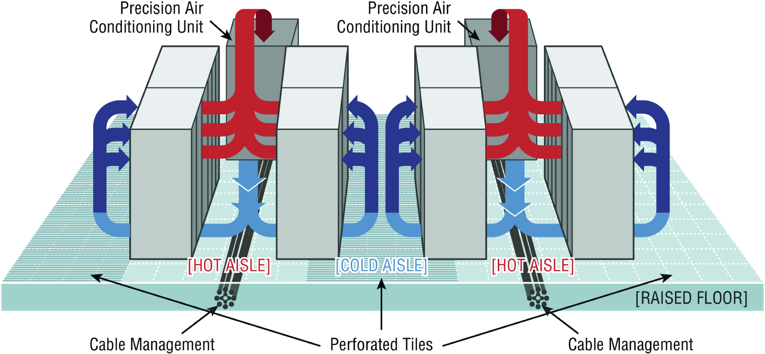
FIGURE 21.15 Hot and cold aisles
- Tool Safety It's worth mentioning again that the first step on safely using tools is to make sure you're properly grounded. Besides practicing tool safety for your own welfare, you should do so to protect the equipment. Here are some specific guidelines to follow:
- Avoid using pencils inside a computer. They can become a conductor and cause damage.
- Be sure that the tools you are using have not been magnetized. Magnetic fields can be harmful to data stored on magnetic media.
- When using compressed air to clean inside the computer, blow the air around the components with a minimum distance of 4 inches (10 centimeters) from the nozzle.
- Clean the contacts on components with isopropyl alcohol. Do not use rubbing alcohol.
- Never use a standard vacuum cleaner inside a computer case. The plastic parts of the vacuum cleaner can build up static electricity and discharge to the components. Use only vacuums that are approved for electronic components.
- MSDS In the course of installing, servicing, and repairing equipment, you'll come in contact with many different types of materials. Some are safer than others. You can get all the information you need regarding the safe handling of materials by reviewing the Material Safety Data Sheet (MSDS).
Any type of chemical, equipment, or supply that has the potential to harm the environment or people has to have an MSDS associated with it. These are traditionally created by the manufacturer and describe the boiling point, melting point, flash point, and potential health risks. You can obtain them from the manufacturer or from the Environmental Protection Agency (EPA).
Emergency Procedures
Every organization should be prepared for emergencies of all types. If possible, this planning should start with the design of the facility and its layout. In this section, I'll go over some of the components of a well-planned emergency system along with some guidelines for maintaining safety on a day-to-day basis.
- Building Layout Planning for emergencies can start with the layout of the facility. Here are some key considerations:
- All walls should have a two-hour minimum fire rating.
- Doors must resist forcible entry.
- The location and type of fire suppression systems should be known.
- Flooring in server rooms and wiring closets should be raised to help mitigate flooding damage.
- Separate AC units must be dedicated to the information processing facilities.
- Backup and alternate power sources should exist.
- Fire Escape Plan You should develop a plan that identifies the escape route in the event of a fire. You should create a facility map showing the escape route for each section of the building, keeping in mind that it's better to use multiple exits to move people out quickly. These diagrams should be placed in all areas.
- Safety/Emergency Exits All escape routes on the map should have the following characteristics:
- Clearly marked and well lit
- Wide enough to accommodate the expected number of people
- Clear of obstructions
- Fail Open/Fail Close Door systems that have electronic locks may lose power during a fire. When they do, they may lock automatically (fail close) or unlock automatically (fail open). While a fail close setting may enhance security during an electrical outage, you should consider the effect it will have during an evacuation and take steps to ensure that everyone can get out of the building when the time comes.
- Emergency Alert System All facilities should be equipped with a system to alert all employees when a fire or any other type of emergency occurs. It might be advisable to connect the facility to the Emergency Alert System (EAS), which is a national warning system in the United States. One of the functions of this system is to alert the public of local weather emergencies such as tornadoes and flash floods. EAS messages are transmitted via AM and FM radio, broadcast television, cable television, and the Land Mobile Radio Service as well as VHF, UHF, and FiOS (wireline video providers).
- Fire-Suppression Systems While fire extinguishers are important and should be placed throughout a facility, when large numbers of computing devices are present, it is worth the money to protect them with a fire-suppression system. The following types of systems exist:
- Wet pipe systems use water contained in pipes to extinguish the fire.
- Dry pipe systems hold the water in a holding tank instead of in the pipes.
- Preaction systems operate like a dry pipe system except that the sprinkler head holds a thermal-fusible link that must melt before the water is released.
- Deluge systems allow large amounts of water to be released into the room, which obviously makes this not a good choice where computing equipment will be located.
- Today, most companies use a fire suppressant like halon, which is known as a “Clean Agent, an electrically non-conducting, volatile, or gaseous fire extinguisher that does not leave a residue upon evaporation.” Leaving no residue means not rendering inoperative expensive networking equipment as water can do if released in a data center. It's remarkably safe for human exposure, meaning that it won't poison living things, and it will allow you to leave the area safely, returning only after the fire department gives the all-clear.
HVAC
The heating and air-conditioning systems must support the massive amounts of computing equipment deployed by most enterprises. Computing equipment and infrastructure devices like routers and switches do not like the following conditions:
- Heat. Excessive heat causes reboots and crashes.
- High humidity. It causes corrosion problems with connections.
- Low humidity. Dry conditions encourage static electricity, which can damage equipment.
Here are some important facts to know about temperature:
- At 100 degrees, damage starts occurring to magnetic media.
- At 175 degrees, damage starts occurring to computers and peripherals.
- At 350 degrees, damage starts occurring to paper products.
Implementing Network Segmentation
Maintaining security in the network can be made easier by segmenting the network and controlling access from one segment to another. Segmentation can be done at several layers of the OSI model. The most extreme segmentation would be at layer 1 if the networks are actually physically separated from one another. In other cases, it may be sufficient to segment a network at layer 2 or layer 3. Coming up next, we'll look at some systems that require segmentation from other networks at one layer or another.
SCADA Systems/Industrial Control Systems
Industrial control system (ICS) is a general term that encompasses several types of control systems used in industrial production. The most widespread is supervisory control and data acquisition (SCADA). SCADA is a system operating with coded signals over communication channels to provide control of remote equipment. It includes the following components:
- Sensors, which typically have digital or analog I/O, and these signals are not in a form that can be easily communicated over long distances
- Remote terminal units (RTUs), which connect to the sensors and convert sensor data to digital data (includes telemetry hardware)
- Programmable logic controllers (PLCs), which connect to the sensors and convert sensor data to digital data (does not include telemetry hardware)
- Telemetry systems, which connect RTUs and PLCs to control centers and the enterprise
- Human interface, which presents data to the operator
- ICS server, also called a data acquisition server, which uses coded signals over communication channels to acquire information about the status of the remote equipment for display or for recording functions
The distributed control system (DCS) network should be a closed network, meaning it should be securely segregated from other networks. The Stuxnet virus hit the SCADA used for the control and monitoring of industrial processes.
Medianets
Medianets are networks primarily devoted to VoIP and video data that often require segmentation from the rest of the network at some layer. We implement segmentation for two reasons: first, to ensure the security of the data, and second, to ensure that the network delivers the high performance and low latency required by these applications. One such high-demand application is video teleconferencing (VTC), which I'll cover next.
Video Teleconferencing (VTC)
IP video has ushered in a new age of remote collaboration. This has saved a great deal of money on travel expenses and enabled more efficient use of time. When you're implementing IP video systems, consider and plan for the following issues:
- Expect a large increase in the need for bandwidth.
- QoS will need to be configured to ensure performance.
- Storage will need to be provisioned for the camera recordings.
- Initial cost may be high.
There are two types of VTC systems. Let's look at both:
- ISDN The first VTC systems were ISDN based. These systems were based on a standard called H.320. While the bandwidth in each ISDN line is quite low by today's standard (128 Kbps per line), multiple lines could be combined or bonded.
- IP/SIP VTC systems based on IP use a standard called H.323. Since these work on a packet-switched network, you don't need a direct ISDN link between the sites. Session Initiation Protocol (SIP) can also be used, and it operates over IP but lacks many of the structured call control functions that H.323 provides.
Legacy Systems
Legacy systems are systems that are older and incompatible with more modern systems and equipment. They may also be less secure and no longer supported by the vendor. In some cases, these legacy systems, especially with respect to industrial control systems, use propriety protocols that prevent them from communicating on the IP-based network. It's a good idea to segment these systems to protect them from security issues they aren't equipped to handle or even just to allow them to function correctly.
Separate Private/Public Networks
Public IP addressing isn't typically used in a modern network. Instead, private IP addresses are used and network address translation (NAT) services are employed to convert traffic to a public IP address when the traffic enters the Internet. While this is one of the strategies used to conserve the public IP address space, it also serves to segment the private network from the public network (Internet). Hiding the actual IP address (private) of the hosts inside the network makes it very difficult to make an unsolicited connection to a system on the inside of the network from the outside.
Honeypot/Honeynet
Another segmentation tactic is to create honeypots and honeynets. Honeypots are systems strategically configured to be attractive to hackers and to lure them into spending enough time attacking them to allow information to be gathered about the attack. In some cases, entire networks called honeynets are attractively configured for this purpose.
You need to make sure that either of these types of systems do not provide direct connections to any important systems. Their ultimate purpose is to divert attention from valuable resources and to gather as much information about an attack as possible. A tarpit is a type of honeypot designed to provide a very slow connection to the hacker so that the attack takes enough time to be properly analyzed.
Testing Lab
Testing labs are used for many purposes. Sometimes they're created as an environment for developers to test applications. They may also be used to test operating system patches and antivirus updates. These environments may even be virtual environments. Virtualization works well for testing labs because it makes it easier to ensure that the virtual networks have no physical connection to the rest of the network, providing necessary segmentation.
Security
One of the biggest reasons for implementing segmentation is for security purposes. At layer 1, this means complete physical separation. However, if you don't want to go with complete segmentation, you can also segment at layer 2 on switches by implementing VLANs and port security. This can prevent connections between systems that are connected to the same switch. They can also be used to organize users into common networks regardless of their physical location.
If segmentation at layer 3 is required, this is achieved using access control lists on routers to control access from one subnet to another or from one VLAN to another. Firewalls can implement these types of access lists as well.
Compliance
Finally, network segmentation may be required to comply with an industry regulation. For example, while it's not strictly required, the Payment Card Industry Data Security Standard (PCI DSS) strongly recommends that a credit card network should be segmented from the regular network. If you choose not to do this, your entire network must be compliant with all sections of the standard.
Network Optimization
Regardless of how well a network is functioning, you should never stop trying to optimize its performance. This is especially true when latency-sensitive applications such as VoIP, streaming video, and web conferencing are implemented. In the next several sections, I'll discuss some techniques you can use to ensure that these applications and services deliver on their promise of increased functionality.
Reasons to Optimize Your Network's Performance
So why do we have networks, anyway? I don't mean this in a historical sense; I mean pragmatically. The reason they've become such precious resources is that as our world becomes increasingly smaller and more connected we need to be able to keep in touch now more than ever. Networks make accessing resources easy for people who can't be in the same location as the resources they need—including other people.
In essence, networks of all types are really complex tools we use to facilitate communication from afar and to allow lots of us to access the resources we need to keep up with the demands imposed on us in today's lightning-paced world. And use them we do—a lot! And when we have many, many people trying to access one resource like a valuable file server or a shared database, our systems can get as bogged down and clogged as a freeway at rush hour. Just as road rage can result from driving on one of those not-so-expressways, frustrated people can direct some serious hostility at you if the same thing happens when they're trying to get somewhere using a network that's crawling along at snail speed.
This is why optimizing performance is in everyone's best interest—it keeps you and your network's users happily humming along. Optimization includes things like splitting up network segments, stopping unnecessary services on servers, offloading one server's work onto another, and upgrading outmoded hardware devices to newer, faster models. I'll get to exactly how to make all this happen coming up soon, but first, I'm going to talk about the theories behind performance optimization and even more about the reasons for making sure performance is at its best.
In a perfect world, there would be unlimited bandwidth, but in reality, you're more likely to find Bigfoot. So, it's helpful to have some great strategies up your sleeve.
If you look at what computers are used for today, there's a huge difference between the files we transfer now versus those transferred even three to five years ago. Now we do things like watch movies online without them stalling, and we can send huge email attachments. Video teleconferencing is almost more common than Starbucks locations. The point is that the files we transfer today are really large compared to what we sent back and forth just a few years ago. And although bandwidth has increased to allow us to do what we do, there are still limitations that cause network performance to suffer miserably. Let's start with a few reasons why you need to carefully manage whatever amount of precious bandwidth you've got.
Latency Sensitivity
Most of us have clicked to open an application or clicked a web link only to have the computer just sit there staring back at us, helplessly hanging. That sort of lag comes when the resources needed to open the program or take us to the next page are not fully available. That kind of lag on a network is called latency—the time between when data is requested and the moment it actually gets delivered. The more latency, the longer the delay and the longer you have to stare blankly back at your computer screen, hoping something happens soon.
Latency affects some programs more than others. If you are sending an email, it may be annoying to have to wait a few seconds for the email server to respond, but that type of delay isn't likely to cause physical harm to you or a loved one. Applications that are adversely affected by latency are said to have high latency sensitivity. A common example of this is online gaming. Although it may not mean actual life or death, playing certain online games with significant delays can mean the untimely demise of your character—and you won't even know it. Worse, it can affect the entire experience for those playing with you, which can get you booted from some game servers. On a much more serious level, applications like remote surgery also have high latency sensitivity.
High-Bandwidth Applications
Many of the applications we now use over the network would have been totally unserviceable in the past because of the high amount of bandwidth they consume. And even though technology is constantly improving to give us more bandwidth, developers are in hot pursuit, developing new applications that gobble up that bandwidth as soon as it becomes—even in advance of it becoming—available. A couple of good examples of high-bandwidth applications are VoIP and video streaming:
- VoIP Voice over Internet Protocol (VoIP) describes several technologies that work to deliver voice communications over the Internet or other data networks. In many cases, VoIP includes not only voice but video transmissions as well. VoIP allows us to send voice, video, and data all over the same connection to another location. Its most common application is video teleconferencing.
Many companies are investing in VoIP systems to reduce travel costs. Ponying up for pricey plane tickets, lodging, and rental cars adds up fast, so investing in a good VoIP system that allows the company to have virtual conferences with people in another state or country pays for itself in no time.
But sadly, VoIP installations can be stressed heavily by things like really low bandwidth, latency issues, packet loss, jitter, security flaws, and reliability concerns. And in some cases, routing VoIP through firewalls and routers using address translation can prove pretty problematic as well.
- Video Applications Watching real-time video on the Internet today is great if you have a decent high-speed connection. You can watch the news, sports, movies, and pretty much anything else that you watch on television. Although viewing digital media online is so common that anyone born after the year 2000 won't be able to remember a time when we had to watch videos on anything other than a computer, again, this requires lots of bandwidth. And excessive use can cause traffic problems even on the most robust networks!
Other Real-Time Services
While VoIP and video traffic certainly require the most attention with respect to performance and latency, other real-time services are probably in use in your network. We're going to briefly look at presence, another example of real-time services you may not give a lot of thought to, and then I'll compare the use of unicast and multicast in real-time services.
- Presence Presence is a function provided by many collaboration solutions that indicates the availability of a user. It signals to other users whether a user is online, busy, in a meeting, and so forth. If enabled across multiple communication tools, such as IM, phone, email, and videoconferencing, it also can help determine the communication channel on which the user is currently active and therefore which channel provides the best possibility of an immediate response.
- Multicast vs. Unicast Unicast transmissions represent a one-to-one conversation, that is, data sent from a single device to another single device. On the other hand, multicast is a technology that sends information for a single source to multiple recipients and is far superior to using unicast transmission when it comes to video streaming and conferencing.
While unicast transmission creates a data connection and stream for each recipient, multicast uses the same stream for all recipients. This single stream is replicated as needed by multicast routers and switches in the network. The stream is limited to branches of the network topology that actually have subscribers to the stream. This greatly reduces the use of bandwidth in the network.
Uptime
Uptime is the amount of time the system is up and accessible to your end users, so the more uptime you have the better. And depending on how critical the nature of your business is, you may need to provide four-nines or five-nines uptime on your network—that's a lot. Why is this a lot? Because you write out four nines as 99.99 percent, or better, you write out five nines as 99.999 percent! Now that is some serious uptime!
How to Optimize Performance
You now know that bandwidth is to networking as water is to life, and you're one of the lucky few if your network actually has an excess of it. Cursed is the downtrodden administrator who can't seem to find enough, and more fall into this category than the former. At times, your very sanity may hinge upon ensuring that your users have enough available bandwidth to get their jobs done on your network, and even if you've got a 10 Gbps connection, it doesn't mean all your users have that much bandwidth at their fingertips. What it really means is that they get a piece of it, and they share the rest with other users and network processes. Because it's your job to make sure as much of that 1 Gbps as possible is there to use when needed, I'm going to discuss some really cool ways to make that happen for you.
Quality of Service
Quality of service (QoS) refers to the way the resources are controlled so that the quality of service is maintained. It's basically the ability to provide a different priority to one or more types of traffic over other levels for different applications, data flows, or users so that they can be guaranteed a certain performance level.
QoS methods focus on one of five problems that can affect data as it traverses network cable:
- Delay Data can run into congested lines or take a less-than-ideal route to the destination, and delays like these can make some applications, such as VoIP, fail. This is the best reason to implement QoS when real-time applications are in use in the network—to prioritize delay-sensitive traffic.
- Dropped Packets Some routers will drop packets if they receive them while their buffers are full. If the receiving application is waiting for the packets but doesn't get them, it will usually request that the packets be retransmitted—another common cause of service delays.
- Error Packets can be corrupted in transit and arrive at the destination in an unacceptable format, again requiring retransmission and resulting in delays.
- Jitter Not every packet takes the same route to the destination, so some will be more delayed than others if they travel through a slower or busier network connection. The variation in packet delay is called jitter, and this can have a nastily negative impact on programs that communicate in real time.
- Out-of-Order Delivery Out-of-order delivery is also a result of packets taking different paths through the network to their destinations. The application at the receiving end needs to put them back together in the right order for the message to be completed, so if there are significant delays or the packets are reassembled out of order, users will probably notice degradation of an application's quality.
QoS can ensure that applications with a required bit rate receive the necessary bandwidth to work properly. Clearly, on networks with excess bandwidth, this is not a factor, but the more limited your bandwidth is, the more important a concept like this becomes.
DSCP
One of the methods that can be used for classifying and managing network traffic and providing quality of service (QoS) on modern IP networks is Differentiated Services Code Point (DSCP), or DiffServ. DiffServ uses a 6-bit code point (DSCP) in the 8-bit Differentiated Services field (DS field) in the IP header for packet classification. This allows for the creation of traffic classes that can be used to assign priorities to various traffic classes.
In theory, a network could have up to 64 different traffic classes using different DSCPs, but most networks use the following traffic classifications:
- Default, which is typically best-effort traffic
- Expedited Forwarding (EF), which is dedicated to low-loss, low-latency traffic
- Assured Forwarding (AF), which gives assurance of delivery under prescribed conditions
- Class Selector, which maintains backward compatibility with the IP Precedence field (a field formerly used by the Type of Service (ToS) function)
Class of Service (COS)
The second method of providing traffic classification and thus the ability to treat the classes differently is a 3-bit field called the Priority Code Point (PCP) within an Ethernet frame header when VLAN tagged frames as defined by IEEE 802.1Q are used.
This method is defined in the IEEE 802.1p standard. It describes eight different classes of service as expressed through the 3-bit PCP field in an IEEE 802.1Q header added to the frame. These classes are shown in Table 21.2.
TABLE 21.2 Eight levels of QoS
| Level | Description |
|---|---|
| 0 | Best effort |
| 1 | Background |
| 2 | Standard (spare) |
| 3 | Excellent load (business-critical applications) |
| 4 | Controlled load (streaming media) |
| 5 | Voice and video (interactive voice and video, less than 100 ms latency and jitter) |
| 6 | Layer 3 Network Control Reserved Traffic (less than 10 ms latency and jitter) |
| 7 | Layer 2 Network Control Reserved Traffic (lowest latency and jitter) |
QoS levels are established per call, per session, or in advance of the session by an agreement known as a service-level agreement (SLA).
Unified Communications
Increasingly, workers and the organizations for which they work are relying on new methods of communicating and working together. Unified communications (UC) is the integration of real-time communication services such as instant messaging with non-real-time communication services such as unified messaging (integrated voicemail, email, SMS, and fax). UC allows an individual to send a message on one medium and receive the same communication on another medium.
UC systems are made of several components that make sending a message on one medium and receiving the same communication on another medium possible. The following may be part of a UC system:
- UC Servers The UC server is the heart of the system. It provides call control mobility services and administrative functions. It may be a stand-alone device or in some cases a module that is added to a router.
- UC Devices UC devices are the endpoints that may participate in unified communications. This includes computers, laptops, tablets, and smartphones.
- UC Gateways UC gateways are used to tie together geographically dispersed locations that may want to make use of UC facilities. They are used to connect the IP-based network with the public switched telephone network (PSTN).
Traffic Shaping
Traffic shaping, or packet shaping, is another form of bandwidth optimization. It works by delaying packets that meet a certain criteria to guarantee usable bandwidth for other applications. Traffic shaping is basically traffic triage—you're really just delaying attention to some traffic so other traffic gets A-listed through. Traffic shaping uses bandwidth throttling to ensure that certain data streams don't send too much data in a specified period of time as well as rate limiting to control the rate at which traffic is sent.
Most often, traffic shaping is applied to devices at the edge of the network to control the traffic entering the network, but it can also be deployed on devices within an internal network. The devices that control it have what's called a traffic contract that determines which packets are allowed on the network and when. You can think of this as the stoplights on busy freeway on-ramps, where only so much traffic is allowed onto the road at one time, based on predefined rules. Even so, some traffic (like carpools and emergency vehicles) is allowed on the road immediately. Delayed packets are stored in the managing device's first-in, first-out (FIFO) buffer until they're allowed to proceed per the conditions in the contract. If you're the first car at the light, this could happen immediately. If not, you get to go after waiting briefly until the traffic in front of you is released.
Load Balancing
Load balancing refers to a technique used to spread work out to multiple computers, network links, or other devices.
Using load balancing, you can provide an active/passive server cluster in which only one server is active and handling requests. For example, your favorite Internet site might actually consist of 20 servers that all appear to be the same exact site because that site's owner wants to ensure that its users always experience quick access. You can accomplish this on a network by installing multiple, redundant links to ensure that network traffic is spread across several paths and to maximize the bandwidth on each link.
Think of this as having two or more different freeways that will both get you to your destination equally well—if one is really busy, just take the other one.
High Availability
High availability is a system-design protocol that guarantees a certain amount of operational uptime during a given period. The design attempts to minimize unplanned downtime—the time users are unable to access resources. In almost all cases, high availability is provided through the implementation of duplicate equipment (multiple servers, multiple NICs, etc.). Organizations that serve critical functions obviously need this; after all, you really don't want to blaze your way to a hospital ER only to find that they can't treat you because their network is down!
One of the highest standards in uptime is the ability to provide the five-nines availability I mentioned earlier. This actually means the network is accessible 99.999 percent of the time—way impressive! Think about this. In one non-leap year, there are 31,536,000 seconds. If you are available 99.999 percent of the time, it means you can be down only 0.001 percent of the time, or a total of 315.36 seconds, or 5 minutes and 15.36 seconds per year—wow!
Caching Engines
A cache is a collection of data that duplicates key pieces of original data. Computers use caches all the time to temporarily store information for faster access, and processors have both internal and external caches available to them, which speeds up their response times.
A caching engine is basically a database on a server that stores information people need to access fast. The most popular implementation of this is with web servers and proxy servers, but caching engines are also used on internal networks to speed up access to things like database services.
Fault Tolerance
Fault tolerance means that even if one component fails, you won't lose access to the resource it provides. To implement fault tolerance, you need to employ multiple devices or connections that all provide a way to access the same resource(s).
A familiar form of fault tolerance is configuring an additional hard drive to be a mirror image of another so that if either one fails, there's still a copy of the data available to you. In networking, fault tolerance means that you have multiple paths from one point to another. What's really cool is that fault-tolerant connections can be configured to be available either on a standby basis only or all the time if you intend to use them as part of a load-balancing system.
Archives/Backups
While providing redundancy to hardware components is important, the data that resides on the components must also be archived in case a device where the data is stored has to be replaced. It could be a matter of replacing a hard drive on which the data cannot be saved and restoring the data from tape backup. Or suppose RAID has been enabled in a system; in that case, the loss of a single hard drive will not present an immediate loss of access to the data (although a replacement of the bad drive will be required to recover from another drive failure).
With regard to the data backups, they must be created on a schedule and tested regularly to ensure that a data restoration is successful. The three main data backup types are full backups, differential backups, and incremental backups. But to understand them, you must grasp the concept of archive bits. When a file is created or updated, the archive bit for the file is enabled. If the archive bit is cleared, the file will not be archived during the next backup. If the archive bit is enabled, the file will be archived during the next backup.
The end result is that each type of backup differs in the amount of time taken, the amount of data backed up, whether unchanged data is backed up repeatedly, and the number of tapes required to restore the data. Keep these key facts in mind:
- If you use a full backup once a week and differential backups the other days of the week, to restore you will only need the last full backup tape and the last differential tape. This is the fastest restore.
- If you use a full backup once a week and incremental backups the other days of the week, to restore you will need the last full backup tape and all of the incremental tapes. This is the slowest restore.
A comparison of the three main backup types is shown in Figure 21.16.
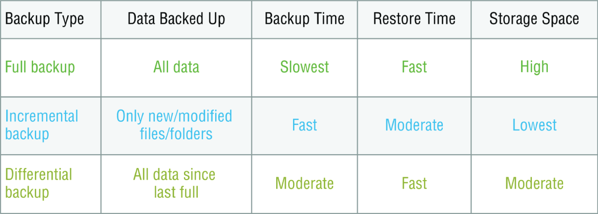
FIGURE 21.16 Backup types
Common Address Redundancy Protocol
Common Address Redundancy Protocol (CARP) provides IP-based redundancy, allowing a group of hosts on the same network segment (referred to as a redundancy group) to share an IP address. One host is designated the master and the rest are backups. The master host responds to any traffic or ARP requests directed toward it. Each host may belong to more than one redundancy group at a time.
One of its most common uses is to provide redundancy for devices such as firewalls or routers. The virtual IP address (this is another name for the shared group IP address) will be shared by a group of routers or firewalls.
The client machines use the virtual IP address as their default gateway. In the event that the master router suffers a failure or is taken offline, the IP will move to one of the backup routers and service will continue. Other protocols that use similar principles are Virtual Router Redundancy Protocol (VRRP) and the Hot Standby Router Protocol (HSRP).
Virtual Networking
Over the last few years, one of the most significant developments helping to increase the efficient use of computing resources—leading to an increase in network performance without an increase in spending on hardware—has been the widespread adoption of virtualization technology. You can't read an industry publication without coming across the term cloud computing within 45 seconds!
The concept of virtualization is quite simple. Instead of dedicating a physical piece of hardware to every server, run multiple instances of the server operating system, each in its own “virtual environment” on the same physical piece of equipment. This saves power, maximizes the use of memory and CPU resources, and can even help to “hide” the physical location of each virtual server.
Virtual computing solutions come from a number of vendors. The following are some of the more popular currently:
- VMware vSphere
- Microsoft Hyper-V
- Citrix XenServer
All of these solutions work on the same basic concept but each has its own unique features, and of course all claim to be the best solution. In the following sections, I will discuss the building blocks of virtualization rather than the specific implementation from any single vendor.
On-site vs. Off-site
Often you hear the terms public cloud and private cloud. Clouds can be thought of as virtual computing environments where virtual servers and desktops live and can be accessed by users. A private cloud is one in which this environment is provided to the enterprise by a third party for a fee. This is a good solution for a company that has neither the expertise nor the resources to manage its own cloud yet would like to take advantage of the benefits that cloud computing offers:
- Increased performance
- Increased fault tolerance
- Constant availability
- Access from anywhere
These types of clouds might be considered off-site or public. On the other hand, for the organization that has the expertise and resources, a private or on-site solution might be better and might be more secure. This approach will enjoy the same benefits as a public cloud and may offer more precise control and more options to the organization.
Virtual Networking Components
The foundation of virtualization is the host device, which may be a workstation or a server. This device is the physical machine that contains the software that makes virtualization possible and the containers or virtual machines for the guest operating systems. The host provides the underlying hardware and computing resources, such as processing power, memory, and disk and network I/O, to the VMs. Each guest is a separate and independent instance of an operating system and application software. From a high level, the relationship is shown in Figure 21.17.
Virtualization can be deployed in several different ways to deliver cost-effective solutions to different problems. Each of the following components can have its place in the solution:
- Hypervisor The host is responsible for allocating compute resources to each of the VMs as specified by the configuration. The software that manages all of this is called the hypervisor. Based on parameters set by the administrator, the hypervisor may take various actions to maintain the performance of each guest as specified by the administrator. This may include the following actions:
- Turning off a VM not in use
- Taking CPU resources away from one VM and allocating them to another
- Turning on additional VMs when required to provide fault tolerance
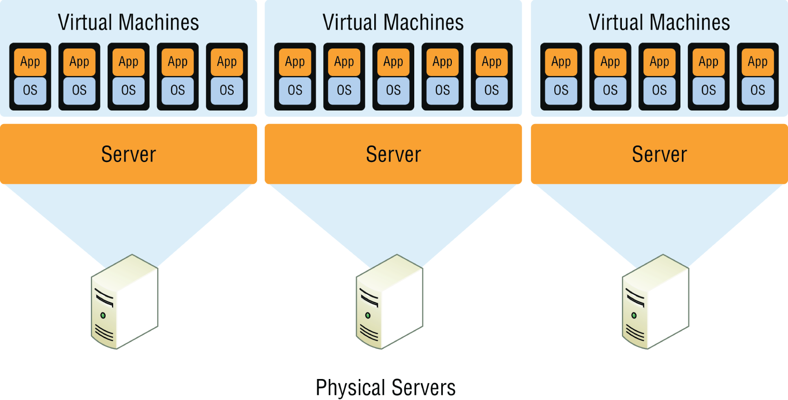
FIGURE 21.17 Guests and hosts
The exact nature of the relationship between the hypervisor, the host operating system, and the guest operating systems depends on the type of hypervisor in use. There are two types of hypervisors in use today. Let's review both of these.
- Type 1 A Type 1 hypervisor (or native, bare metal) runs directly on the host's hardware to control the hardware and to manage guest operating systems. A guest operating system runs on another level above the hypervisor. Examples of these are VMware vSphere and Microsoft Hyper-V.
- Type 2 A Type 2 hypervisor runs within a conventional operating system environment. With the hypervisor layer as a distinct second software level, guest operating systems run at the third level above the hardware. VMware Workstation and VirtualBox exemplify Type 2 hypervisors. A comparison of the two approaches is shown in Figure 21.18.
- Virtual Servers Virtual servers can perform all the same functions as physical servers but can enjoy some significant advantages. By clustering a virtual server with other virtual servers located on different hosts, you can achieve fault tolerance in the case of a host failure. Increased performance can also be derived from this approach.
The virtualization software can allow you to allocate CPU and memory resources to the virtual machines (VMs) dynamically as needed to ensure that the maximum amount of computing power is available to any single VM at any moment while not wasting any of that power on an idle VM. In fact, in situations where VMs have been clustered, they may even be suspended or powered down in times of low demand in the cluster.
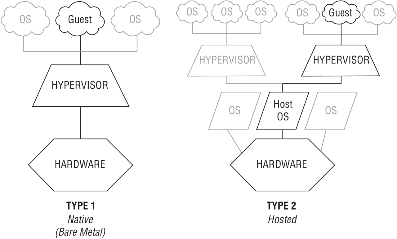
FIGURE 21.18 Hypervisors
- Virtual Switches Virtual switches are software versions of a layer 2 switch that can be used to create virtual networks. They can be used for the same purposes as physical switches. VLANs can be created, virtual servers can be connected to the switches, and the virtual network can be managed, all while residing on the same physical box. These switches can also span multiple hosts (the physical machines that house multiple virtual servers, desktops, and switches are called hosts).
Distributed virtual switches are those switches that span multiple hosts, and they are what links together the VMs that are located on different hosts yet are members of the same cluster.
- Virtual vs. Physical NICs Figure 21.19 shows the relationship between a physical server and the virtual servers and virtual switches that it hosts. The virtual servers, called virtual machines (VMs), have virtual network cards (vNICs) that connect to the virtual switch. Keep in mind that all three of these components are software running on the same physical server. Then the virtual switch makes a software connection to the physical NIC on the physical host, which makes a physical connection to the physical switch in the network.
It is interesting to note and important to be aware of the fact that the IP address of the physical NIC in Figure 21.19 will actually be transmitting packets from multiple MAC addresses since each of the virtual servers will have a unique virtual MAC address.
- Virtual Routers In virtualized environments, virtual routers are typically implemented as specialized software. They consist of individual routing and forwarding tables, each of which could be considered a virtual router.
- Virtual Firewall Virtual firewalls are also implemented as software in the virtualized environment. Like their physical counterparts, they can be used to restrict traffic between virtual subnets created by virtual routers.
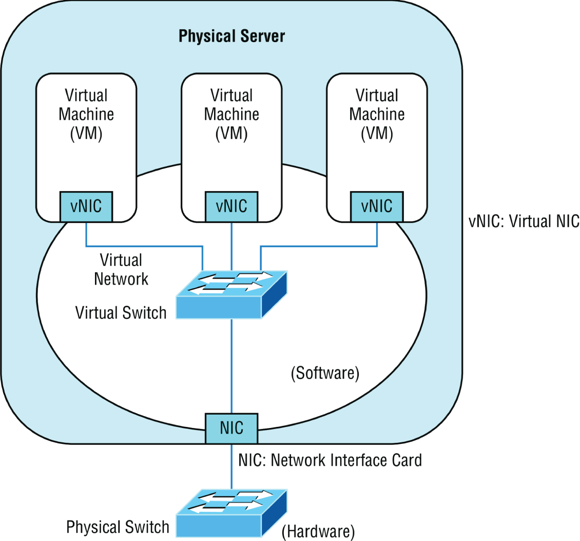
FIGURE 21.19 Virtualization
- Software-Defined Networking Software-defined networking (SDN) is an approach to computer networking that allows network administrators to manage network services through abstraction of lower-level functionality. SDN architectures decouple network control and forwarding functions, enabling network control to become directly programmable and the underlying infrastructure to be abstracted from applications and network services.
- Virtual Desktops Using operating system images for desktop computers is not a new concept, but delivering these desktop images to users from a virtual environment when they start their computer is. This allows for the user desktop to require less computing power, especially if the applications are also delivered virtually and those applications are running in a VM in the cloud rather than in the local desktop eating up local resources. Another benefit of using virtual desktops is the ability to maintain a consistent user environment (same desktop, applications, etc.), which can enhance user support.
Thin computing takes this a step further. In this case, all of the computing is taking place on the server. A thin client is simply displaying the output from the operating system running in the cloud, and the keyboard is used to interact with that operating system in the cloud. Does this sound like dumb terminals with a GUI to anyone yet? Back to the future indeed! The thin client needs very little processing power for this job.
- Virtual PBX Virtual PBX is an example of what is called Software as a Service (SaaS). A hosting company manages the entire phone system for the company, freeing the organization from the need to purchase and manage the physical equipment that would be required otherwise to provide the same level of service. To the outside world, the company appears to have a professional phone system while everything is actually being routed through the hosting company's system.
- Network as a Service (NaaS) Now that you know what SaaS is you can probably guess what NaaS is. You guessed it: a network hosted and managed by a third party on behalf of the company. For many enterprises, it makes more sense to outsource the management of the network to a third party when it is not cost effective to maintain a networking staff.
An example of this is the Cisco OpenStack cloud operating system, which is an open-source platform that provides computers and storage.
Storage Area Network
Storage area networks (SANs) comprise high-capacity storage devices that are connected by a high-speed private network (separate from the LAN) using a storage-specific switch. This storage information architecture addresses the collection, management, and use of data. In this section, we'll take a look at the protocols that can be used to access the data and the client systems that can use those various protocols. We'll also look at an alternative to a SAN: network-attached storage (NAS).
- iSCSI Internet Small Computer Systems Interface (iSCSI) is an IP-based networking storage standard method of encapsulating SCSI commands (which are used with storage area networks) within IP packets. This allows the use of the same network for storage as is used for the balance of the network. A comparison of a regular SAN that uses the Fibre Channel protocol, and one using iSCSI is shown in Figure 21.20. I'll talk more about Fibre Channel later in this list.
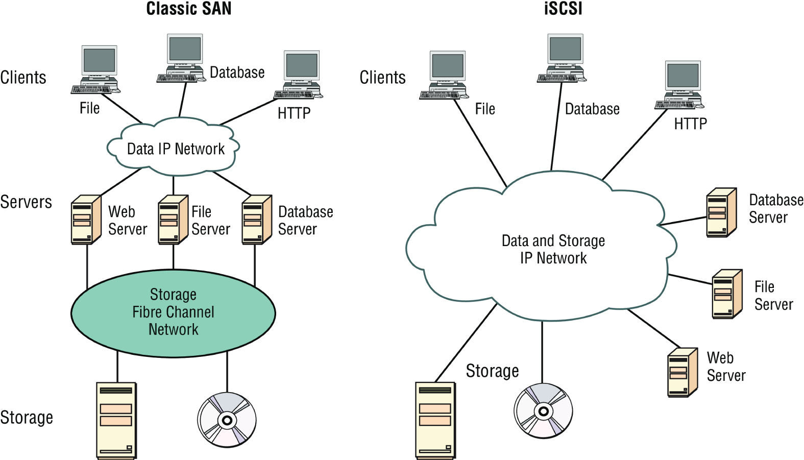
FIGURE 21.20 Classic SAN vs. iSCSI
- InfiniBand InfiniBand is a communications standard that provides high performance and low latency. It is utilized as a direct, or switched, interconnect between servers and storage systems as well as an interconnect between storage systems. It uses a switched fabric topology. The adaptors can exchange information on QoS.
- Fibre Channel Fibre Channel, or FC, is a high-speed network technology (commonly running at 2, 4, 8, and 16 gigabits per second rates) primarily used to connect computer data storage. It operates on an optical network that is not compatible with the regular IP-based data network. As you can see in Figure 21.20, this protocol runs on a private network that connects the servers to the storage network.
Fibre-Channel over Ethernet (FCoE), on the other hand, encapsulates Fibre Channel traffic within Ethernet frames much like iSCSI encapsulates SCSI commands in IP packets. However, unlike iSCSI, FCoE does not use IP at all, but does allow this traffic on the IP network.
- Jumbo Frames Jumbo frames are Ethernet frames with more than 1500 bytes of payload. Jumbo frames with more than 9000-byte payloads have the potential to reduce overhead and CPU cycles. In high-speed networks such as those typically used in a SAN, it may be advisable to enable jumbo frames to improve performance.
- Network Attached Storage Network attached storage (NAS) serves the same function as SAN, but clients access the storage in a different way. In a NAS configuration, almost any machine that can connect to the LAN (or is interconnected to the LAN through a WAN) can use protocols such as NFS, SMB2/3, and HTTPS to connect to the NAS and share files. In a SAN configuration, only devices that can use the Fibre Channel SCSI network can access the data, so it's typically done through a server with this capability. A comparison of the two systems is shown in Figure 21.21.
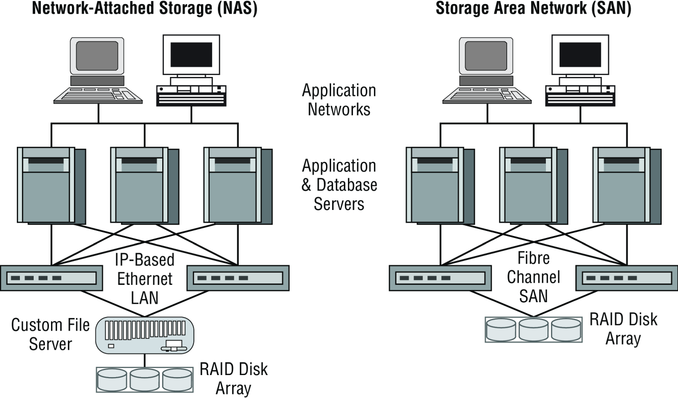
FIGURE 21.21 NAS and SAN
Cloud Concepts
Cloud storage locates the data on a central server, but unlike with an internal data center in the LAN, the data is accessible from anywhere and in many cases from a variety of device types. Moreover, cloud solutions typically provide fault tolerance and dynamic computer resource (CPU, memory, network) provisioning.
Cloud deployments can differ in two ways:
- The entity that manages the solution
- The percentage of the total solution provided by the vendor
First, let's look at the options relative to the entity that manages the solution:
- Private cloud: This is a solution owned and managed by one company solely for that company's use.
- Public cloud: This is a solution provided by a third party. It offloads the details to the third party but gives up some control and can introduce security issues.
- Hybrid cloud: This is some combination of private and public. For example, perhaps you only use the facilities of the provider but still manage the data yourself.
- Community cloud: This is a solution owned and managed by a group of organizations that create the cloud for a common purpose.
There are several levels of service that can be made available through a cloud deployment:
- Infrastructure as a Service (IaaS). The vendor provides the hardware platform or data center, and the company installs and manages its own operating systems and application systems.
- Platform as a Service (PaaS). The vendor provides the hardware platform or data center and the software running on the platform.
- Software as a Service (SaaS). The vendor provides the entire solution. This includes the operating system, infrastructure software, and the application.
- Desktop as a Service (DaaS). The end user's PC is hosted in the cloud and accessed remotely using a web browser or a small piece of client software. The desktop interface is streamed to the client but all Window or Linux desktops, storage, and applications are securely running in the data center.
Infrastructure as Code
With the new hyperscale cloud data centers, it is no longer practical to configure each device in the network individually. Also, configuration changes happen so frequently it would be impossible for a team of engineers to keep up with the manual configuration tasks. Infrastructure as Code (IaC) is the managing and provisioning of infrastructure through code instead of through manual processes.
The concept of Infrastructure as Code allows all configurations for the cloud devices and networks to be abstracted into machine-readable definition files instead of physical hardware configurations. IaC manages the provisioning through code so manually making configuration changes is no longer required.
These configuration files contain the infrastructure requirements and specifications. They can be stored for repeatable use, distributed to other groups, and versioned as you make changes. Faster deployment speeds, fewer errors, and consistency are advantages of Infrastructure as Code over the older, manual process.
Deploying your infrastructure as code allows you to divide your infrastructure into modular components that can be combined in different ways using automation. Code formats include JSON and YAML, and they are used by tools such as Ansible, Salt, Chef, Puppet, Terraform, and AWS CloudFormation.
Automation/Orchestration
Automation and orchestration define configuration, management, and the coordination of cloud operations. Automation involves individual tasks that do not require human intervention and are used to create workflows that are referred to as orchestration. This allows you to easily manage very complex and large tasks using code instead of a manual process.
Automation is a single task that orchestration uses to create the workflow. By using orchestration in the cloud, you can create a complete virtual data center that includes all compute, storage, database, networking, security, management, and any other required services. Very complex tasks can be defined in code and used to create your environment.
Common automation tools used today include Puppet, Docker, Jenkins, Terraform, Ansible, Kubernetes, CloudBees, CloudFormation, Chef, and Vagrant.
Connectivity Options
By default, traffic into and out of your public cloud traverses the Internet. This is a good solution in many cases, but if you require additional security when accessing your cloud resources and exchanging your data, there are two common solutions that we will discuss. The first is a virtual private network (VPN) that sends data securely over the Internet or dedicated connections. The second solution is to install a private non-Internet connection and then a direct connection can be configured.
Virtual Private Network (VPN)
Cloud providers offer site-to-site VPN options that allow you to establish a secure and protected network connection across the public Internet. The VPN connection verifies that both ends of the connection are legitimate and then establishes encrypted tunnels to route traffic from your data center to your cloud resources. If a bad actor intercepts the data, they will not be able to read it due to the encryption of the traffic.
VPNs can be configured with redundant links to back up each other or to load-balance the traffic for higher-speed interconnections.
Another type of VPN allows desktops, laptops, tablets, and other devices to establish individual secure connections into your cloud deployment.
Private Direct Connection
A dedicated circuit can be ordered and installed between your data center and an interconnection provider or directly to the cloud company. This provides a secure, low latency connection with predictable performance.
Direct connection speeds usually range from 1 Gbps to 10 Gbps and can be aggregated together. For example, four 10 Gbps circuits can be installed from your data center to the cloud company for a total aggregate bandwidth of 40 Gbps.
It is also a common practice to establish a VPN connection over the private link for encryption of data in transit.
There are often many options when connecting to the cloud provider that allow you to specify which geographic regions to connect to as well as which areas inside of each region, such as storage systems or your private virtual cloud.
Internet exchange providers maintain dedicated high speed connections to multiple cloud providers and will connect a dedicated circuit from your facility to the cloud providers as you specify.
There are several ways to connect to a virtual server that is in a cloud environment:
- Remote Desktop: While the VPN connection connects you to the virtual network, an RDP connection can be directly connected to a server. If the server is a Windows server, then you will use the Remote Desktop Connection (RDC) client. If it is a Linux server, then the connection will most likely be an SSH connection to the command line.
- File Transfer Protocol (FTP) and Secure File Transfer Protocol (SFTP): The FTP/FTPS server will need to be enabled on the Windows/Linux server and then you can use the FTP/FTPS client or work at the command line. This is best when performing bulk data downloads.
- VMware Remote Console: This allows you to mount a local DVD, hard drive, or USB drive to the virtual server. This is handy for uploading ISO or installation media to the cloud server.
Multitenancy
Public clouds host hundreds of thousands of different customer accounts in the same cloud. This is often referred to as multitenancy, and it presents a number of technical considerations. Tenants and even networks inside of a customer's account need complete isolation from each other and the ability to selectively and securely interconnect to each other. Multitenancy can also be an issue in a private cloud where the development, test, and production networks should be securely isolated.
In a private cloud, the tenants may be different groups or departments within a single company, while in a public cloud, entirely different organizations share services such as compute and storage systems that are isolated from each other.
Multitenant clouds offer isolated space in the data centers to run services such as compute, storage, databases, development applications, artificial intelligence, network applications (such as firewalls and load balancers), and many other services. Think of this as your own private data center in the cloud.
Each tenant controls access, security roles, permissions inside your space, and traffic in and out of your virtual private cloud. All resources are not accessible unless you explicitly allow them to be.
Software multitenancy refers to an architecture where a single instance of an application runs on a server and is shared by multiple tenants.
With software multitenancy, the application software is designed to provide every tenant a dedicated instance of the application, including the data, security, and configuration management. Many instances of the same application support different tenants.
Elasticity
One of the benefits of deploying your workloads in the cloud is to take advantage of the dynamic allocation of cloud resources. Elasticity allows you to meet the fluctuating workload requirements by adding or removing resources in near real time.
Elasticity is the process that cloud providers offer to allocate the desired amount of service resources needed to run your workloads at any given moment.
Elasticity provides on-demand resources such as computing instances or stage space that can meet your existing workloads and automatically adds or subtracts capacity to meet peak and off-peak workloads.
For example, you could be hosting an e-commerce site in the public cloud and expect a large increase in traffic for a big sale you are advertising. Your deployment can be configured to monitor activity and, if needed, add more capacity to meet the demand. When the demand lowers, by using network automation, you can automatically remove that capacity, allowing you to only pay for the cloud resources you actually need and use.
Elasticity allows you to add services such as storage and compute on-demand, often in seconds or minutes.
Scalability
Scalability is a cloud feature that allows you to use cloud resources that meet your current workload needs and later migrate to a larger system to handle growth. Scalability allows you to better manage static resources. With the pay-as-you-go pricing model of the cloud, you do not have to buy expensive hardware that you may outgrow. You can use the cloud to stop the lower-performing services and migrate to larger instances. There are two types of scalabilities, scaling up to a larger server instance or scaling out by adding additional cloud servers in parallel to handle the larger workloads.
Scalability enables you to reliably grow your cloud deployments based on demand, whereas elasticity enables you to scale resources up or down based on real-time workload requirements. This allows you to efficiently manage resources and costs.
Security Implications/Considerations
While an entire book could be written on the security implications of the cloud, there are some concerns that stand above the others. Among them are these:
- While clouds increasingly contain valuable data, they are just as susceptible to attacks as on-premises environments. Cases such as the
Salesforce.comincident in which a technician fell for a phishing attack that compromised customer passwords remind us of this. - Customers are failing to ensure that the provider keeps their data safe in multitenant environments. They are failing to ensure that passwords are assigned, protected, and changed with the same attention to detail they might desire.
- No specific standard has been developed to guide providers with respect to data privacy.
- Data security varies greatly from country to country, and customers have no idea where their data is located at any point in time.
Relationship Between Local and Cloud Resources
When comparing the advantages of local and cloud environments and the resources that reside in each, several things stand out:
- A cloud environment requires very little infrastructure investment on the part of the customer, while a local environment requires an investment in both the equipment and the personnel to set it up and manage it.
- A cloud environment can be extremely scalable and at a moment's notice, while scaling a local environment either up or out requires an investment in both equipment and personnel.
- Investments in cloud environments involve monthly fees rather than capital expenditures as would be required in a local environment.
- While a local environment provides total control for the organization, a cloud takes some of that control away.
- While you always know where your data is in a local environment, that may not be the case in a cloud, and the location may change rapidly.
Locating and Installing Equipment
When infrastructure equipment is purchased and deployed, the ultimate success of the deployment can depend on selecting the proper equipment, determining its proper location in the facility, and installing it correctly. Let's look at some common data center or server room equipment and a few best practices for managing these facilities.
Main Distribution Frame
The main distribution frame connects equipment (inside plant) to cables and subscriber carrier equipment (outside plant). It also terminates cables that run to intermediate distribution frames distributed throughout the facility.
Intermediate Distribution Frame
An intermediate distribution frame (IDF) serves as a distribution point for cables from the main distribution frame (MDF) to individual cables connected to equipment in areas remote from these frames. The relationship between the IDFs and the MDF is shown in Figure 21.22.
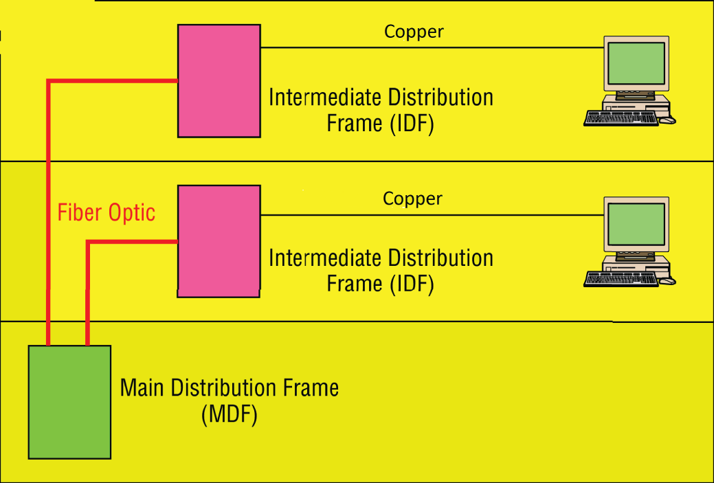
FIGURE 21.22 MDF and IDFs
Cable Management
While some parts of our network may be wireless, the lion's share of the network will be connected with cables. The cables come together in large numbers at distribution points where managing them becomes important both to protect the integrity of the cables and to prevent overheating of the infrastructure devices caused by masses of unruly cabling. The points of congestion typically occur at the patch panels.
Patch panels terminate cables from wall or data outlets. These masses of wires that emerge from the wall in a room will probably feed to the patch panel in a cable tray, which I'll talk more about soon. The critical maintenance issues at the patch panel are to ensure that cabling from the patch panel to the switch is neat, that the patch cables are as short as possible without causing stress on the cables, and that the positioning of the cabling does not impede air flow to the devices, which can cause overheating.
Power Management
Computing equipment of all types needs clean and constant power. Power fluctuations of any sort, especially complete outages and powerful surges, are a serious matter. In this section, we'll look at power issues and devices that can be implemented to avoid or mitigate them.
- Power Converters Power conversion is the process of converting electric energy from one form to another. This conversion could take several forms:
- AC to DC
- From one voltage level to another
- From one frequency to another
Power converters are devices that make these conversions, and they typically are placed inline, where the energy flowing into one end is converted to another form when it exits the converter.
- Circuits In situations where high availability is required, it may be advisable to provision multiple power circuits to the facility. This is sometimes called A+B or A/B power. To provision for A+B power, you should utilize a pair of identically sized circuits (e.g., 2 × 20 amperes). In the final analysis, even these systems can fail you in some natural disasters and so you should always also have power generators as well as a final backup.
- UPS All infrastructure systems and servers should be connected to an uninterruptible power supply (UPS). As described in Chapter 15, “High Availability and Disaster Recovery,” a UPS can immediately supply power from a battery backup when a loss of power is detected. They provide power long enough for you to either shut the system down gracefully or turn on a power generator.
- Inverters A power inverter is a type of power converter that specifically converts DC to AC. It produces no power and must be connected to a DC source.
- Power Redundancy While the facility itself needs redundant power circuits and backup generators, a system can still fail if the power supply in the device fails. Mission-critical devices should be equipped with redundant power supplies, which can mitigate this issue.
Device Placement
When locating equipment in a data center, server room, or wiring closet, you should take several issues into consideration when placing the equipment.
- Air Flow Air flow around the equipment is crucially important to keep devices running. When hot air is not removed from the area and replaced with cooler air, the devices overheat and start doing things like rebooting unexpectedly. Even if the situation doesn't reach that point, the high heat will shorten the life of costly equipment.
One of the approaches that has been really successful is called hot/cold aisles. As explained earlier in this chapter, hot aisle/cold aisle design involves lining up racks in alternating rows with cold air intakes facing one way and hot air exhausts facing the other. The rows composed of rack fronts are called cold aisles. Typically, cold aisles face air conditioner output ducts. The rows the heated exhausts pour into are called hot aisles. They face air conditioner return ducts. Moreover, all of the racks and the equipment they hold should never be on the floor. There should be a raised floor to provide some protection against water.
- Cable Trays Masses of unruly cables can block air flow and act as a heat blanket on the equipment if the situation is bad enough. Cable trays are metal trays used to organize the cabling neatly and keep it away from the areas where it can cause heat buildup. In Figure 21.23, some examples of cable tray components are shown. These are used to organize the cables and route them as needed.
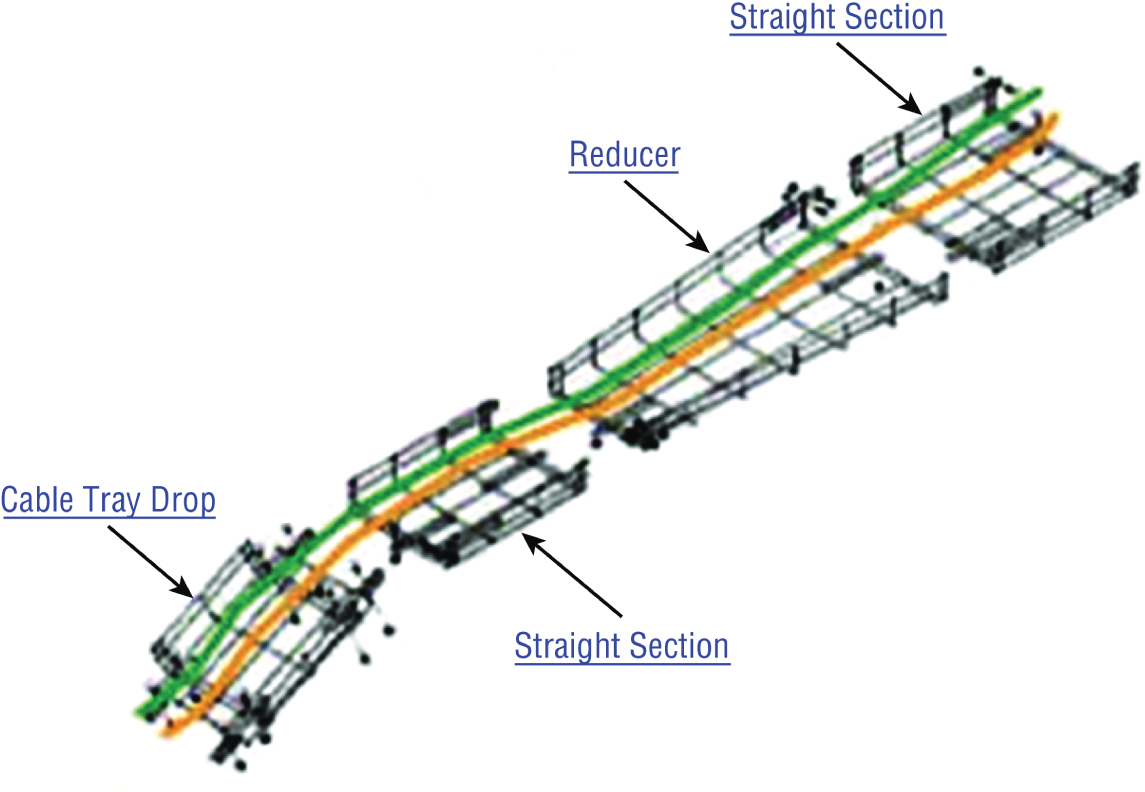
FIGURE 21.23 Cable trays
- Rack Systems Rack systems are used to hold and arrange the servers, routers, switches, firewalls, and other rack-ready equipment. Rack devices are advertised in terms of Us. U is the standard unit of measure for designating the vertical usable space, or the height of racks. 1U is equal to 1.75 inches. For example, a rack designated as 20U has 20 rack spaces for equipment and 35 (20 × 1.75) inches of vertical usable space. You should be familiar with the following types of rack systems and components:
- Server Rail Racks Server rail racks are used to hold servers in one of the types of racks described next. They are designed to hold the server while allowing the server to be slid out from the rack for maintenance.
- Two-Post Racks A two-post rack is one in which only two posts run from the floor. These posts may reach to the ceiling or they may not (freestanding). Several sizes of two-post racks are shown in Figure 21.24.
- Four-Post Racks As you would expect, these racks have four rails and can be either floor to ceiling or freestanding. One is shown in Figure 21.25.
- Freestanding racks A freestanding rack is one that does not reach the ceiling and stands on its own. A four-post freestanding rack is shown in Figure 21.26.
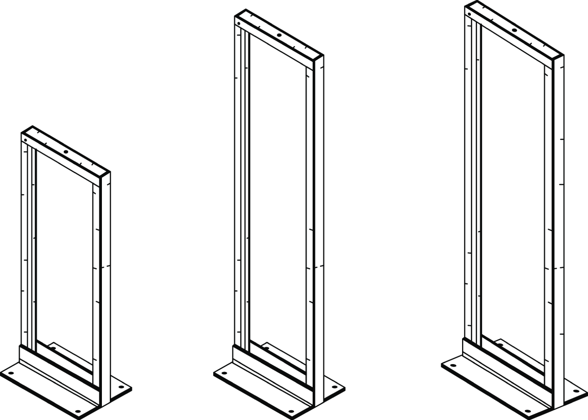
FIGURE 21.24 Two-post racks
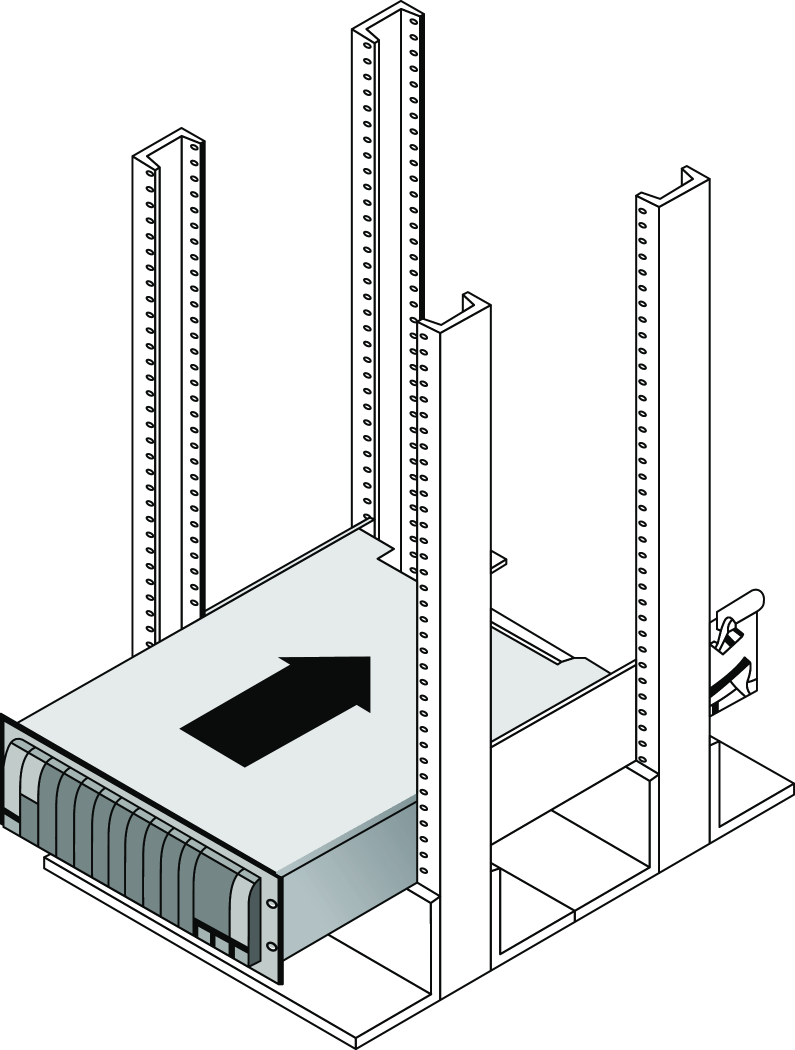
FIGURE 21.25 Four-post rack

FIGURE 21.26 Freestanding rack
Labeling
In a data center, server room, or wiring closet, correct and updated labeling of ports, systems, circuits, and patch panels can prevent a lot of confusion and mistakes when configuration changes are made. Working with incorrect or incomplete (in some cases nonexistent) labeling is somewhat like trying to locate a place with an incorrect or incomplete map. In this section, we'll touch on some of the items that should be correctly labeled.
- Port Labeling Ports on switches, patch panels, and other systems should be properly labeled, and the wall outlets to which they lead should match! You should arrive at an agreement as to the naming convention to use so that all technicians are operating from the same point of reference. They also should be updated any time changes are made that require an update.
- System Labeling Other systems that are installed in racks, such as servers, firewall appliances, and redundant power supplies, should also be labeled with IP addresses and DNS names that the devices possess.
- Circuit Labeling Circuits entering the facility should also be labeled. Label electrical receptacles, circuit breaker panels, and power distribution units. Include circuit information, voltage and amperage, the type of electrical receptacle, and where in the data center the conduit terminates.
- Naming Conventions A naming system or convention guides and organizes labeling and ensures consistency. No matter what name or numbering system you use, be consistent.
- Patch Panel Labeling The key issue when labeling patch panels is to ensure that they're correct. Also, you need to make sure that the wall outlet they're connected to is the same. The American National Standards Institute/Telecommunications Industry Association (ANSI/TIA) 606-B.1 Administration Standard for Telecommunications Infrastructure for identification and labeling approved in April 2012 provides clear specifications for labeling and administration best practices across all electrical and network systems premise classes, including large data centers.
Rack Monitoring
Racks should contain monitoring devices that can be operated remotely. These devices can be used to monitor the following issues:
- Temperature
- Humidity
- Physical security (open doors)
- Smoke
- Water leaks
- Vibration
Rack Security
Rack devices should be secured from theft. There are several locking systems that can be used to facilitate this. These locks are typically implemented in the doors on the front of a rack cabinet:
- Swing handle/wing knob locks with common key
- Swing handle/wing knob locks with unique key
- Swing handle with number and key lock
- Electronic locks
- Radio-frequency identification (RFID) card locks
Change Management Procedures
Throughout this chapter I've stressed that network operations need to occur in a controlled and managed fashion. For this to occur, an organization must have a formal change management process in place. The purpose of this process is to ensure that all changes are approved by the proper personnel and are implemented in a safe and logical manner. Let's look at some of the key items that should be included in these procedures.
Document Reason for a Change
Clearly, every change should be made for a reason, and before the change is even discussed, that reason should be documented. During all stages of the approval process (discussed later), this information should be clearly communicated and attached to the change under consideration.
Change Request
A change should start its life as a change request. This request will move through various stages of the approval process and should include certain pieces of information that will guide those tasked with approving or denying it.
Configuration Procedures
The exact steps required to implement the change and the exact devices involved should be clearly detailed. Complete documentation should be produced and submitted with a formal report to the change management board.
Rollback Process
Changes always carry a risk. Before any changes are implemented, plans for reversing the changes and recovering from any adverse effects should be identified. Those making the changes should be completely briefed in these rollback procedures, and they should exhibit a clear understanding of them prior to implementing the changes.
Potential Impact
While unexpected adverse effects of a change can't always be anticipated, a good-faith effort should be made to identity all possible systems that could be impacted by the change. One of the benefits of performing this exercise is that it can identify systems that may need to be more closely monitored for their reaction to the change as the change is being implemented.
Notification
When all systems and departments that may be impacted by the change are identified, system owners and department heads should be notified of all changes that could potentially affect them. One of the associated benefits of this is that it creates additional monitors for problems during the change process.
Approval Process
Requests for changes should be fully vetted by a cross section of users, IT personnel, management, and security experts. In many cases, it's wise to form a change control board to complete the following tasks:
- Assure that changes made are approved, tested, documented, and implemented correctly.
- Meet periodically to discuss change status accounting reports.
- Maintain responsibility for assuring that changes made do not jeopardize the soundness of the verification system.
Maintenance Window
A maintenance window is an amount of time a system will be down or unavailable during the implementation of changes. Before this window of time is specified, all affected systems should be examined with respect to their criticality in supporting mission-critical operations. It may be that the time required to make the change may exceed the allowable downtime a system can suffer during normal business hours, and the change may need to be implemented during a weekend or in the evening.
Authorized Downtime
Once the time required to make the change has been compared to the maximum allowable downtime a system can suffer and the optimum time for the change is identified, the authorized downtime can be specified. This amounts to a final decision on when the change will be made.
Notification of Change
When the change has been successfully completed and a sufficient amount of time has elapsed for issues to manifest themselves, all stakeholders should be notified that the change is complete. At that time, these stakeholders (those possibly affected by the change) can continue to monitor the situation for any residual problems.
Documentation
The job isn't complete until the paperwork is complete. In this case, the following should be updated to reflect the changed state of the network:
- Network configurations
- Additions to network
- Physical location changes
Summary
In this chapter, I talked a lot about the layout and basic architectures in modern data centers. I started off discussing the tiering of the data center networks, including the access/distribution/core designs, and then you learned about the newer spine-leaf architectures. Next you learned about the placement of network hardware in the data center with top of rack and backbone switching being introduced and discussed. The flow of data inside the data center was introduced with North-South traffic going into and out of a data center and East-West traffic being inside the data center between servers and storage or server-to-server flows.
We went into great detail on cloud computing because it continues to evolve and take on more and more IT workloads. You learned about the most common services models, including Infrastructure as a Service, Platform as a Service, and Software as a Service.
You learned about software-defined networking and how SDN is used to centrally configure large networks. We discussed the components of a software-defined network, including the management and forwarding planes, the use of application programming interfaces, and the north- and southbound configuration flows.
Next we looked at managing network documentation and the tools needed for that, such as SNMP and schematics. You learned about both physical and logical diagrams, managing IP addresses, and vendor documentation.
Network monitoring helps address performance issues in the network and includes creating baselines, defining processes such as log viewing, and patch management. You learned about the documentation processes including change management, security policies, statements of work, service-level agreements, and master license agreements. Next, we touched on the regulations you may need to adhere to depending on your business.
Safety is important in the data center, including proper electrical grounding and preventing static discharge. Installation safety includes handling of heavy equipment, rack installations, and tool safety. Fire suppression, emergency alerting, and HVAC systems are all a part of safely operating a data center.
We discussed network optimization and the network requirements for real-time applications such as voice and video, including low latency and jitter. Quality of service can be implemented in the network to prioritize applications.
You were introduced to the modern cloud designs and architectures that are highly virtualized. The two types of hypervisors were discussed along with the virtual machines and NICs that are part of virtualization. I compared private, public, and hybrid clouds and you learned about cloud operations using infrastructure as code, automation, orchestration, scalability, and elasticity.
Finally we ended with device placement in the data center and how to design for air flow and cabling.
I talked a lot about the documentation aspects of network administration. I started off discussing physical diagrams and schematics and moved on to the logical form as well as configuration-management documentation. You learned about the importance of these diagrams as well as the simple to complex forms they can take and the tools used to create them—from pencil and paper to high-tech AutoCAD schematics. You also found out a great deal about creating performance baselines. After that, I delved deep into a discussion of network policies and procedures and how regulations can affect how you manage your network.
Next, you learned about network monitoring and optimization and how monitoring your network can help you find issues before they develop into major problems. You learned that server operating systems and intelligent network devices have built-in graphical monitoring tools to help you troubleshoot your network.
We got into performance optimization and the many theories and strategies you can apply to optimize performance on your network. All of them deal with controlling the traffic in some way and include methods like QoS, traffic shaping, load balancing, high availability, and the use of caching servers. We discussed how Common Address Redundancy Protocol (CARP) can be used to increase availability of gateways and firewalls. You also learned how important it is to ensure that you have plenty of bandwidth available for any applications that vitally need it, like critical service operations, VoIP, and real-time multimedia streaming.
Exam Essentials
- Compare and contrast cloud technologies. Understand the differences between IaaS, SaaS, PaaS, and DaaS. Also know the difference between a NAS and a SAN.
- Understand common data center network architectures. Data center architectures include the standard three-tier core, distribution/aggregation, and access/edge model. Newer architectures use a spine and leaf design for a higher throughput switching fabric. Traffic flows in the data center or cloud are often referred to as North-South, which refers to traffic into and out of the data center. East-West traffic refers to the flows inside the data center between devices such as storage and servers.
- Know the basic concepts of software-defined networking. SDN controllers are centralized management plane systems that use application programming interfaces (APIs) to configure the data network as a whole, which eliminates the need to log in and make changes individually to a large number of individual networking devices. Infrastructure as Code allows you to divide your infrastructure into modular components that can be combined in different ways using automation.
- Know the basic cloud architectures. Having many different customers or groups all sharing the same cloud provider's data centers is called multitenancy. Understand that elasticity is the ability to scale your resources up and down on demand and scalability is the ability to reliably grow your cloud deployment based on demand. The public cloud relies on the Internet for access, however, private direct connections can be deployed for secure, reliable, low-latency connections from your data center to your cloud operations.
- Understand the difference between a physical network diagram and a logical network diagram. A physical diagram shows all of the physical connections and devices, and in many cases, the cables or connections between the devices. It's a very detail-oriented view of the hardware on your network. A logical network diagram takes a higher-level view, such as your subnets and the protocols those subnets use to communicate with each other.
- Identify the elements of unified communications technology. This includes the proper treatment of traffic types such as VoIP and video. You should also understand what UC servers, devices, and gateways are. Finally, describe the methods used to provide QoS to latency-sensitive traffic.
- Understand the difference between policies, procedures, and regulations. A policy is created to give users guidance as to what is acceptable behavior on the network. Policies also help resolve problems before they begin by specifying who has access to what resources and how configurations should be managed. Procedures are steps to be taken when an event occurs on the network, such as what to do when a user is fired or how to respond to a natural disaster. Regulations are imposed on your organization; you are required to follow them, and if you don't, you may be subject to punitive actions.
- Know how your servers and network devices can help you monitor your network. Most servers and network devices have monitoring tools built in that are capable of tracking data and events on your network. These include graphical tools as well as log files.
- Understand several theories of performance optimization. There are several ways to manage traffic on your network to speed up access and in some cases guarantee available bandwidth to applications. These include QoS, traffic shaping, load balancing, high availability, and using caching servers.
- Know some examples of bandwidth-intensive applications. Two examples of high-bandwidth applications are Voice over IP (VoIP) and real-time video streaming.
- Describe the major building blocks of virtualization. Understand how virtual servers, virtual switches, and virtual desktops are used to supply the infrastructure to deliver cloud services. Differentiate on-site or private clouds from off-site or public cloud services. Identify services that can be provided, such as Network as a Service (NaaS) and Software as a Service (SaaS).
- Summarize safety and environmental issues in the data center. Understand electrical safety as it relates to both devices and humans. Understand the use of fire suppression systems. Describe proper emergency procedures.
Written Lab
You can find the answers to the written labs in Appendix A. In this section, write the answers to the following management questions:
- ___________________ and ___________________ are the two main components of modern data center fabric-based networks.
- Traffic flow inside the data center is referred to as ___________________.
- _____________ and orchestration define configuration, management, and the coordination of cloud operations.
- ___________________ is a single task that orchestration uses to create the workflow.
- ___________________ allows you to add cloud services such as storage and compute on demand, often in seconds or minutes.
- A standard of normal network performance is called ___________________.
- If you need to connect two PCs directly together using their network adapters, what type of cable do you need?
- What is another name for using virtualization to provide services?
- List at least three major components of virtualization.
- ___________________ is the managing and provisioning of resources through software instead of through manual processes.
Review Questions
You can find the answers to the review questions in Appendix B.
- On a three-tiered network, servers connect at which level?
- Core
- Distribution
- Aggregation
- Access
- Which type of cable will have the pins in the same order on both connectors?
- Crossover cable
- Straight-through cable
- Console cable
- Telephone cable
- Which pins are switched in a crossover cable?
- 1 and 2, 3 and 4
- 1 and 3, 2 and 6
- 2 and 4, 5 and 7
- 1 and 4, 5 and 8
- UTP cable has specific colors for the wire associated with each pin. Based on the TIA/EIA 568B wiring standard, what is the correct color order, starting with pin 1?
- White/Orange, Orange, Blue, White/Green, White/Blue, Green, White/Brown, Brown
- Orange, White/Orange, White/Green, Blue, White/Blue, White/Brown, Brown, Green
- White/Orange, Orange, White/Green, Blue, White/Blue, Green, White/Brown, Brown
- White/Green, Green, White/Orange, Blue, White/Blue, Orange, White/Brown, Brown
- What is used to describe network traffic flows that remain inside the data center?
- Ingress
- Aggregation
- East-West
- North-South
- Which of the following govern how the network is configured and operated as well as how people are expected to behave on the network?
- Baselines
- Laws
- Policies
- Procedures
- You have upgraded the firmware on your switches and access points. What documentation do you need to update?
- Baselines and configuration documentation
- Physical network diagram
- Logical network diagram
- Wiring schematics
- Where does the SDN controller interface with the switching fabric?
- Spine
- Control plane
- Forwarding plane
- P Core
- Load testing, connectivity testing, and throughput testing are all examples of what?
- Load balancing
- Network monitoring
- Packet sniffing
- Traffic shaping
- Abstracting the Cloud hardware into software objects for automated configuration is referred to as ___________________.
- Application programming interface
- Elasticity
- Infrastructure as Code
- Software-defined networking
- Which of the following identifies steps to recover from adverse effects caused by a change?
- Rollback process
- Approvable process
- Notification process
- Impact assessment
- After a network configuration change has been made, which three of the following is not a document that needs to be updated?
- Network configurations
- Additions to the network
- Physical location changes
- Application document
- When the vendor provides the hardware platform or data center, and the company installs and manages its own operating systems and application systems, which service type is being used?
- Software as a Service
- Infrastructure as a Service
- Platform as a Service
- Desktop as a Service
- You have added a new cable segment to your network. You need to make sure you document this for troubleshooting purposes. What should you update?
- The disaster recovery plan
- The wiring schematics
- The router connections document
- The baseline document
- Machine to machine configuration interfaces are called ___________________ .
- Northbound interfaces
- Southbound interfaces
- APIs
- SDN
- Public clouds are divided into logical groupings that allow many different customers to access a section as if it were their own private data center. This is known as ___________________ .
- Multi-fabric
- Elasticity
- Multitenancy
- Platform as a Service
- Which of the following are methods used to connect a private cloud to a public cloud? (Choose all that apply.)
- Internet
- SDN
- VPN
- Direct Connect
- Virtual switches
- Which of the following are reasons to optimize network performance? (Choose all that apply.)
- Maximizing uptime
- Minimizing latency
- Using VoIP
- Using video applications
- None of the above
- What term describes technologies that can deliver voice communications over the Internet?
- Jitter
- Uptime
- Voice over Internet Protocol
- None of the above
- Which virtualization approach is run as an application?
- Type 1 hypervisor
- Type 2 hypervisor
- SDN
- Virtual switch
- None of the above