
Chapter 1
Introduction to Networks
You'd have to work pretty hard these days to find someone who would argue when we say that our computers have become invaluable to us personally and professionally. Our society has become highly dependent on the resources they offer and on sharing them with each other. The ability to communicate with others—whether they're in the same building or in some faraway land—completely hinges on our capacity to create and maintain solid, dependable networks.
And those vitally important networks come in all shapes and sizes—ranging from small and simple to humongous and super complicated. But whatever their flavor, they all need to be maintained properly, and to do that well, you have to understand networking basics. The various types of devices and technologies that are used to create networks, as well as how they work together, is what this book is about, and I'll go through this critical information one step at a time with you. Understanding all of this will not only equip you with a rock-solid base to build on as you gain IT knowledge and grow in your career, it will also arm you with what you'll need to ace the Network+ certification exam!
First Things First: What's a Network?
The dictionary defines the word network as “a group or system of interconnected people or things.” Similarly, in the computer world, the term network means two or more connected computers that can share resources such as data and applications, office machines, an Internet connection, or some combination of these, as shown in Figure 1.1.
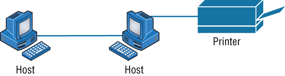
FIGURE 1.1 A basic network
Figure 1.1 shows a really basic network made up of only two host computers connected; they share resources such as files and even a printer hooked up to one of the hosts. These two hosts “talk” to each other using a computer language called binary code, which consists of lots of 1s and 0s in a specific order that describes exactly what they want to “say.”
Next, I'm going to tell you about local area networks, how they work, and even how we can connect LANs together. Then, later in this chapter, I'll describe how to connect remote LANs together through something known as a wide area network.
The Local Area Network
Just as the name implies, a local area network (LAN) is usually restricted to spanning a particular geographic location such as an office building, a single department within a corporate office, or even a home office.
Back in the day, you couldn't put more than 30 workstations on a LAN, and you had to cope with strict limitations on how far those machines could actually be from each other. Because of technological advances, all that's changed now, and we're not nearly as restricted in regard to both a LAN's size and the distance a LAN can span. Even so, it's still best to split a big LAN into smaller logical zones known as workgroups to make administration easier.
In a typical business environment, it's a good idea to arrange your LAN's workgroups along department divisions; for instance, you would create a workgroup for Accounting, another one for Sales, and maybe another for Marketing—you get the idea. Figure 1.2 shows two separate LANs, each as its own workgroup.
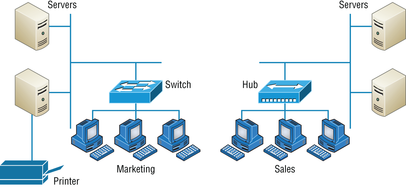
FIGURE 1.2 Two separate LANs (workgroups)
First, don't stress about the devices labeled hub and switch—these are just connectivity devices that allow hosts to physically connect to resources on an LAN. Trust me; I'll describe them to you in much more detail in Chapter 5, “Networking Devices.”
Anyway, back to the figure. Notice that there's a Marketing workgroup and a Sales workgroup. These are LANs in their most basic form. Any device that connects to the Marketing LAN can access the resources of the Marketing LAN—in this case, the servers and printer.
There are two problems with this:
- You must be physically connected to a workgroup's LAN to get the resources from it.
- You can't get from one LAN to the other and use the server data and printing resources remotely.
This is a typical network issue that's easily resolved by using a cool device called a router to connect the two LANs, as shown in Figure 1.3.
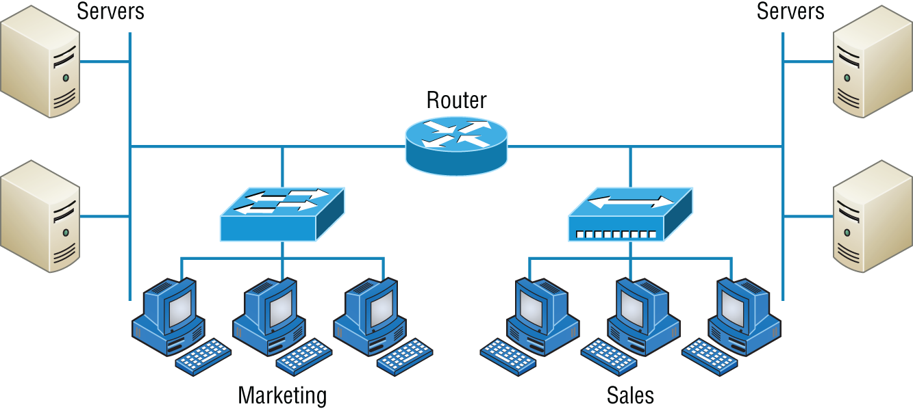
FIGURE 1.3 A router connects LANs.
Nice—problem solved! Even though you can use routers for more than just connecting LANs, the router shown in Figure 1.3 is a great solution because the host computers from the Sales LAN can get to the resources (server data and printers) of the Marketing LAN, and vice versa.
Now, you might be thinking that we don't really need the router—that we could just physically connect the two workgroups with a type of cable that would allow the Marketing and Sales workgroups to hook up somehow. Well, we could do that, but if we did, we would have only one big, cumbersome workgroup instead of separate workgroups for Marketing and Sales, and that kind of arrangement just isn't practical for today's networks.
This is because with smaller, individual-yet-connected groups, the users on each LAN enjoy much faster response times when accessing resources, and administrative tasks are a lot easier too. Larger workgroups run more slowly because there's a legion of hosts within them that are all trying to get to the same resources simultaneously. So the router shown in Figure 1.3, which separates the workgroups while still allowing access between them, is a really great solution!
So let me define the other terms I've used so far: workstations, servers, and hosts.
Common Network Components
There are a lot of different machines, devices, and media that make up our networks. Let's talk about three of the most common:
- Workstations
- Servers
- Hosts
Workstations
Workstations are often seriously powerful computers that run more than one central processing unit (CPU) and whose resources are available to other users on the network to access when needed. With this much power, you might think I am describing a server—not quite because there is an important difference between these devices that I'll cover in the next section. Workstations are often employed as systems that end users use on a daily basis. Don't confuse workstations with client machines, which can be workstations but not always. People often use the terms workstation and client interchangeably. In colloquial terms, this isn't a big deal; we all do it. But technically speaking, they are different. A client machine is any device on the network that can ask for access to resources like a printer or other hosts from a server or powerful workstation.
Servers
Servers are also powerful computers. They get their name because they truly are “at the service” of the network and run specialized software known as the network operating system to maintain and control the network.
In a good design that optimizes the network's performance, servers are highly specialized and are there to handle one important labor-intensive job. This is not to say that a single server can't do many jobs, but more often than not, you'll get better performance if you dedicate a server to a single task. Here's a list of common dedicated servers:
- File Server Stores and dispenses files
- Mail Server The network's post office; handles email functions
- Print Server Manages printers on the network
- Web Server Manages web-based activities by running Hypertext Transfer Protocol Secure (HTTPS) for storing web content and accessing web pages
- Fax Server The “memo maker” that sends and receives paperless faxes over the network
- Application Server Manages network applications
- Telephony Server Handles the call center and call routing and can be thought of as a sophisticated network answering machine
- Proxy Server Handles tasks in the place of other machines on the network, particularly an Internet connection
As I said, servers are usually dedicated to doing one specific important thing within the network. Not always, though—sometimes they have more than one job. But whether servers are designated for one job or are network multitaskers, they can maintain the network's data integrity by backing up the network's software and providing redundant hardware (for fault tolerance). And no matter what, they all serve a number of client machines.
Back in Figure 1.2, I showed you an example of two really simple LAN networks. I want to make sure you know that servers must have considerably superior CPUs, hard-drive space, and memory—a lot more than a simple client's capacity—because they serve many client machines and provide any resources they require. Because they're so important, you should always put your servers in a very secure area. My company's servers are in a locked server room because not only are they really pricey workhorses, they also store huge amounts of important and sensitive company data, so they need to be kept safe from any unauthorized access.
In Figure 1.4, you can see a network populated with both workstations and servers. Also notice that the hosts can access the servers across the network, which is pretty much the general idea of having a network in the first place!
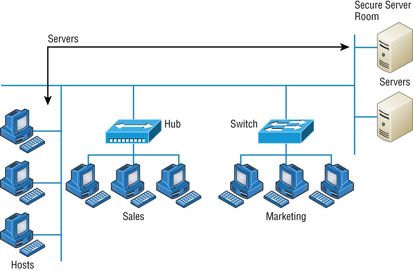
FIGURE 1.4 A network populated with servers and workstations
You probably picked up on the fact that there are more workstations here than servers, right? Think of why that is. If you answered that it's because one server can provide resources to what can sometimes be a huge number of individual users at the same time but workstations don't, you nailed it!
Hosts
This can be kind of confusing because when people refer to hosts, they really can be referring to almost any type of networking devices—including workstations and servers. But if you dig a bit deeper, you'll find that usually this term comes up when people are talking about resources and jobs that have to do with Transmission Control Protocol/Internet Protocol (TCP/IP). The scope of possible machines and devices is so broad because, in TCP/IP-speak, host means any network device with an IP address. Yes, you'll hear IT professionals throw this term around pretty loosely; for the Network+ exam, stick to the definition of hosts as being network devices, including workstations and servers, with IP addresses.
Here's a bit of background: The name host harks back to the Jurassic period of networking when those dinosaurs known as mainframes were the only intelligent devices able to roam the network. These were called hosts whether they had TCP/IP functionality or not. In that bygone age, everything else in the network-scape was referred to as dumb terminals because only mainframes—hosts—were given IP addresses. Another fossilized term from way back then is gateways, which was used to talk about any layer 3 machines like routers. We still use these terms today, but they've evolved a bit to refer to the many intelligent devices populating our present-day networks, each of which has an IP address. This is exactly the reason you hear host used so broadly.
Metropolitan Area Network
A metropolitan area network (MAN) is just as it sounds, a network covering a metropolitan area used to interconnect various buildings and facilities usually over a carrier provided network. Think of a MAN as a concentrated WAN and you've got it. MANs typically offer high speed interconnections using in-ground fiber optics and can be very cost effective for high-speed interconnects.
Wide Area Network
There are legions of people who, if asked to define a wide area network (WAN), just couldn't do it. Yet most of them use the big dog of all WANs—the Internet—every day! With that in mind, you can imagine that WAN networks are what we use to span large geographic areas and truly go the distance. Like the Internet, WANs usually employ both routers and public links, so that's generally the criteria used to define them.
Here's a list of some of the important ways that WANs are different from LANs:
- WANs usually need a router port or ports.
- WANs span larger geographic areas and/or can link disparate locations.
- WANs are usually slower.
- We can choose when and how long we connect to a WAN. A LAN is all or nothing—our workstation is connected to it either permanently or not at all, although most of us have dedicated WAN links now.
- WANs can utilize either private or public data transport media such as phone lines.
We get the word Internet from the term internetwork. An internetwork is a type of LAN and/or WAN that connects a bunch of networks, or intranets. In an internetwork, hosts still use hardware addresses to communicate with other hosts on the LAN. However, they use logical addresses (IP addresses) to communicate with hosts on a different LAN (on the other side of the router).
And routers are the devices that make this possible. Each connection into a router is a different logical network. Figure 1.5 demonstrates how routers are employed to create an internetwork and how they enable our LANs to access WAN resources.
The Internet is a prime example of what's known as a distributed WAN—an internetwork that's made up of a lot of interconnected computers located in a lot of different places. There's another kind of WAN, referred to as centralized, that's composed of a main, centrally located computer or location that remote computers and devices can connect to. A good example is remote offices that connect to a main corporate office, as shown in Figure 1.5.
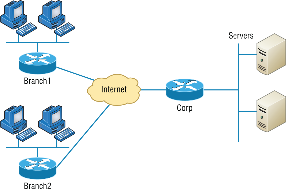
FIGURE 1.5 An internetwork
Personal Area Network
For close proximity connections there are PANs, or personal area networks. These are seen with smartphones and laptops in a conference room where local connections are used to collaborate and send data between devices. While a PAN can use a wired connection such as Ethernet or USB, it is more common that short distance wireless connections are used such as Bluetooth, infrared, or ZigBee.
PANs are intended for close proximity between devices such as connecting to a projector, printer, or a coworker's computer, and they extend usually only a few meters.
Campus Area Network
A CAN, or campus area network, covers a limited geographical network such as a college or corporate campus. The CAN typically interconnects LANs in various buildings and offers a Wi-Fi component for roaming users.
A campus area network is between a LAN and WAN in scope. They are larger than a local area network (LAN) but smaller than a metropolitan area network (MAN) or wide area network (WAN).
Most CANs offer Internet connectivity as well as access to data center resources.
Storage Area Network
A storage area network (SAN) is designed for, and used exclusively by, storage systems. SANs interconnect servers to storage arrays containing centralized banks of hard drive or similar storage media. SANs are usually only found in data centers and do not mix traffic with other LANs. The protocols are designed specifically for storage with Fibre Channel being the most prevalent along with iSCSI. The network hardware is different from LAN switches and routers and are designed specifically to carry storage traffic.
Software-Defined Wide Area Network
A software-defined wide area network (SDWAN) is a virtual WAN architecture that uses software to manage connectivity, devices, and services and can make changes in the network based on current operations.
SDWANs integrate any type of transport architectures such as MPLS, LTE, and broadband Internet services to securely connect users to applications. The SDWAN controller can make changes in real time to add or remove bandwidth or to route around failed circuits. SDWANs can simplify wide area networking management and operations by decoupling the networking hardware from its control mechanism.
Multiprotocol Label Switching
The term Multiprotocol Label Switching (MPLS), as used in this chapter, will define the actual layout of what is one of the most popular WAN protocols in use today. MPLS has become one of the most innovative and flexible networking technologies on the market, and it has some key advantages over other WAN technologies:
- Physical layout flexibility
- Prioritizing of data
- Redundancy in case of link failure
- One-to-many connection
MPLS is a switching mechanism that imposes labels (numbers) to data and then uses those labels to forward data when it arrives at the MPLS network, as shown in Figure 1.6.
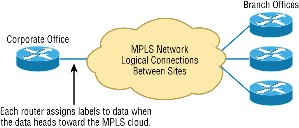
FIGURE 1.6 Multiprotocol Label Switching layout
The labels are assigned on the edge of the MPLS network, and forwarding inside the MPLS network (cloud) is done solely based on labels through virtual links instead of physical links. Prioritizing data is a huge advantage; for example, voice data could have priority over basic data based on the labels. And since there are multiple paths for the data to be forwarded through the MPLS cloud, there's even some redundancy provided as well.
Multipoint Generic Routing Encapsulation
The Multipoint Generic Routing Encapsulation (mGRE) protocol refers to a carrier or service provider offering that dynamically creates and terminates connections to nodes on a network. mGRE is used in Dynamic Multipoint VPN deployments. The protocol enables dynamic connections without having to pre-configure static tunnel endpoints.
The protocol encapsulates user data, creates a VPN connection to one or many nodes, and when completed, tears down the connection.
Network Architecture: Peer-to-Peer or Client-Server?
We've developed networking as a way to share resources and information, and how that's achieved directly maps to the particular architecture of the network operating system software. There are two main network types you need to know about: peer-to-peer and client-server. And by the way, it's really tough to tell the difference just by looking at a diagram or even by checking out live video of the network humming along. But the differences between peer-to-peer and client-server architectures are pretty major. They're not just physical; they're logical differences. You'll see what I mean in a bit.
Peer-to-Peer Networks
Computers connected together in peer-to-peer networks do not have any central, or special, authority—they're all peers, meaning that when it comes to authority, they're all equals. The authority to perform a security check for proper access rights lies with the computer that has the desired resource being requested from it.
It also means that the computers coexisting in a peer-to-peer network can be client machines that access resources and server machines and provide those resources to other computers. This actually works pretty well as long as there isn't a huge number of users on the network, if each user backs things up locally, and if your network doesn't require much security.
If your network is running Windows, macOS, or Linux in a local LAN workgroup, you have a peer-to-peer network. Figure 1.7 gives you a snapshot of a typical peer-to-peer network. Keep in mind that peer-to-peer networks definitely present security-oriented challenges; for instance, just backing up company data can get pretty sketchy!
Since it should be clear by now that peer-to-peer networks aren't all sunshine, backing up all your critical data may be tough, but it's vital! Haven't all of us forgotten where we've put an important file? And then there's that glaring security issue to tangle with. Because security is not centrally governed, each and every user has to remember and maintain a list of users and passwords on each and every machine. Worse, some of those all-important passwords for the same users change on different machines—even for accessing different resources. What a mess!
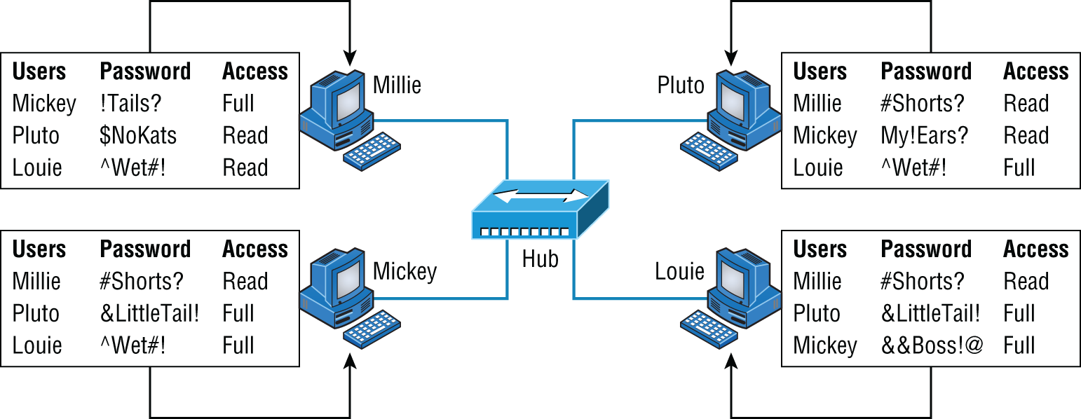
FIGURE 1.7 A peer-to-peer network
Client-Server Networks
Client-server networks are pretty much the polar opposite of peer-to-peer networks because in them, a single server uses a network operating system for managing the whole network. Here's how it works: A client machine's request for a resource goes to the main server, which responds by handling security and directing the client to the desired resource. This happens instead of the request going directly to the machine with the desired resource, and it has some serious advantages. First, because the network is much better organized and doesn't depend on users remembering where needed resources are, it's a whole lot easier to find the files you need because everything is stored in one spot—on that special server. Your security also gets a lot tighter because all usernames and passwords are on that specific server, which is never ever used as a workstation. You even gain scalability—client-server networks can have legions of workstations on them. And surprisingly, with all those demands, the network's performance is actually optimized—nice!
Check out Figure 1.8, which shows a client-server network with a server that has a database of access rights, user accounts, and passwords.
Many of today's networks are hopefully a healthy blend of peer-to-peer and client-server architectures, with carefully specified servers that permit the simultaneous sharing of resources from devices running workstation operating systems. Even though the supporting machines can't handle as many inbound connections at a time, they still run the server service reasonably well. And if this type of mixed environment is designed well, most networks benefit greatly by having the capacity to take advantage of the positive aspects of both worlds.
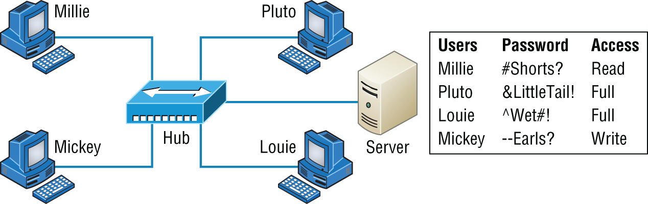
FIGURE 1.8 A client-server network
Physical Network Topologies
Just as a topographical map is a type of map that shows the shape of the terrain, the physical topology of a network is also a type of map. It defines the specific characteristics of a network, such as where all the workstations and other devices are located and the precise arrangement of all the physical media such as cables. On the other hand, the logical topologies we covered earlier delineate exactly how data moves through the network. Now, even though these two topologies are usually a lot alike, a particular network can actually have physical and logical topologies that are very different. Basically, what you want to remember is that a network's physical topology gives you the lay of the land and the logical topology shows how a digital signal or data navigates through that layout.
Here's a list of the topologies you're most likely to run into these days:
- Bus
- Star/hub-and-spoke
- Ring
- Mesh
- Point-to-point
- Point-to-multipoint
- Hybrid
Bus Topology
This type of topology is the most basic one of the bunch, and it really does sort of resemble a bus, but more like one that's been in a wreck! Anyway, the bus topology consists of two distinct and terminated ends, with each of its computers connecting to one unbroken cable running its entire length. Back in the day, we used to attach computers to that main cable with wire taps, but this didn't work all that well so we began using drop cables in their place. If we were dealing with 10Base2 Ethernet, we would slip a “T” into the main cable anywhere we wanted to connect a device to it instead of using drop cables.
Figure 1.9 depicts what a typical bus network's physical topology looks like.
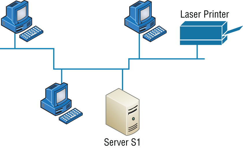
FIGURE 1.9 A typical bus network's physical topology
Even though all the computers on this kind of network see all the data flowing through the cable, only the one computer, which the data is specifically addressed to, actually gets the data. Some of the benefits of using a bus topology are that it's easy to install and it's not very expensive, partly because it doesn't require as much cable as the other types of physical topologies. But it also has some drawbacks: For instance, it's hard to troubleshoot, change, or move, and it really doesn't offer much in the way of fault tolerance because everything is connected to that single cable. This means that any fault in the cable would basically bring the whole network down!
Star Topology
A star (hub-and-spoke) topology's computers are connected to a central point with their own individual cables or wireless connections. You'll often find that central spot inhabited by a device like a hub, a switch, or an access point.
Star topology offers a lot of advantages over bus topology, making it more widely used even though it obviously requires more physical media. One of its best features is that because each computer or network segment is connected to the central device individually, if the cable fails, it only brings down the machine or network segment related to the point of failure. This makes the network much more fault tolerant as well as a lot easier to troubleshoot. Another great thing about a star topology is that it's a lot more scalable—all you have to do if you want to add to it is run a new cable and connect to the machine at the core of the star. In Figure 1.10, you'll find a great example of a typical star topology.
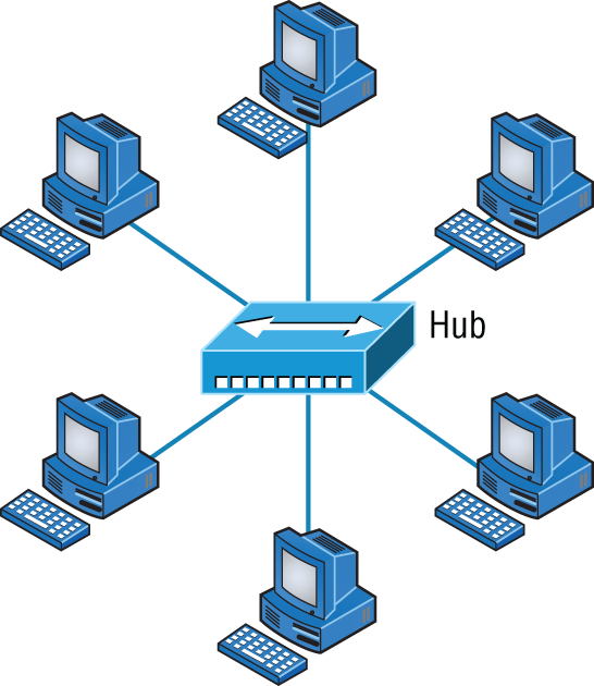
FIGURE 1.10 Typical star topology with a hub
Although it is called a star (hub-and-spoke) topology, it also looks a lot like a bike wheel with spokes connecting to the hub in the middle of the wheel and extending outward to connect to the rim. And just as with that bike wheel, it's the hub device at the center of a star topology network that can give you the most grief if something goes wrong with it. If that central hub happens to fail, down comes the whole network, so it's a very good thing hubs don't fail often!
Just as it is with pretty much everything, a star topology has its pros and cons. But the good news far outweighs the bad, which is why people often opt for star topology. And here's a list of benefits you gain by going with it:
- New stations can be added or moved easily and quickly.
- A single cable failure won't bring down the entire network.
- It's relatively easy to troubleshoot.
And here are the disadvantages to using a star topology:
- The total installation cost can be higher because of the larger number of cables, even though prices are becoming more competitive.
- It has a single point of failure—the hub or other central device.
There are two more sophisticated implementations of a star topology. The first is called a point-to-point link, where you have not only the device in the center of the spoke acting as a hub but also the device on the other end, which extends the network. This is still a star-wired topology, but as I'm sure you can imagine, it gives you a lot more scalability!
Another refined version is the wireless version, but to understand this variety well, you've got to have a solid grasp of all the capabilities and features of any devices populating the wireless star topology. No worries, though—I'll be covering wireless access points later on in Chapter 12, “Wireless Networking.” For now, it's good enough for you to know that access points are pretty much just wireless hubs or switches that behave like their wired counterparts. Basically, they create a point-by-point connection to endpoints and other wireless access points.
Ring Topology
In this type of topology, each computer is directly connected to other computers within the same network. Looking at Figure 1.11, you can see that the network's data flows from computer to computer back to the source, with the network's primary cable forming a ring. The problem is, the ring topology has a lot in common with the bus topology because if you want to add to the network, you have no choice but to break the cable ring, which is likely to bring down the entire network!
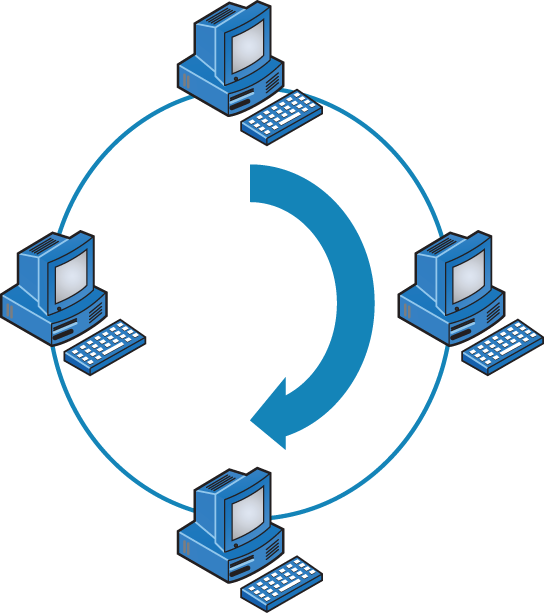
FIGURE 1.11 A typical ring topology
This is one big reason that ring topology isn't very popular—you just won't run into it a lot as I did in the 1980s and early 1990s. It's also pricey because you need several cables to connect each computer, it's really hard to reconfigure, and as you've probably guessed, it's not fault tolerant.
But even with all that being said, if you work at an ISP, you may still find a physical ring topology in use for a technology called SONET or some other WAN technology. However, you just won't find any LANs in physical rings anymore.
Mesh Topology
In this type of topology, you'll find that there's a path from every machine to every other one in the network. That's a lot of connections—in fact, the mesh topology wins the prize for “most physical connections per device”! You won't find it used in LANs very often, if ever, these days, but you will find a modified version of it known as a hybrid mesh used in a restrained manner on WANs, including the Internet.
Often, hybrid mesh topology networks will have quite a few connections between certain places to create redundancy (backup). And other types of topologies can sometimes be found in the mix too, which is another reason it's dubbed hybrid. Just remember that it isn't a full-on mesh topology if there isn't a connection between all devices in the network. And understand that it's fairly complicated. Figure 1.12 gives you a great picture of just how much only four connections can complicate things!
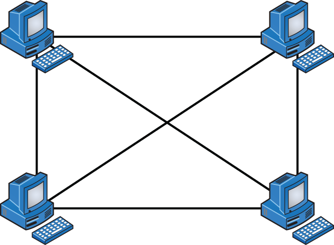
FIGURE 1.12 A typical mesh topology
You can clearly see that everything gets more and more complex as both the wiring and the connections multiply. For each n locations or hosts, you end up with n(n–1)/2 connections. This means that in a network consisting of only four computers, you have 4(4–1)/2, or 6 connections. And if that little network grows to, say, a population of 10 computers, you'll then have a whopping 45 connections to cope with! That's a huge amount of overhead, so only small networks can really use this topology and manage it well. On the bright side, you get a really nice level of fault tolerance, but mesh still isn't used in corporate LANs anymore because they were so complicated to manage.
This is also the reason you'll usually find the hybrid version in today's WANs. In fact, the mesh topology is actually pretty rare now, but it's still used because of the robust fault tolerance it offers. Because you have a multitude of connections, if one goes on the blink, computers and other network devices can simply switch to one of the many redundant connections that are up and running. And clearly, all that cabling in the mesh topology makes it a very pricey implementation. Plus, you can make your network management much less insane than it is with mesh by using what's known as a partial mesh topology solution instead, so why not go that way? You may lose a little fault tolerance, but if you go the partial mesh route, you still get to use the same technology between all the network's devices. Just remember that with partial mesh, not all devices will be interconnected, so it's very important to choose the ones that will be very wisely.
Point-to-Point Topology
As its name implies, in a point-to-point topology you have a direct connection between two routers or switches, giving you one communication path. The routers in a point-to-point topology can be linked by a serial cable, making it a physical network, or if they're located far apart and connected only via a circuit within a Frame Relay or MPLS network, it's a logical network instead.
Figure 1.13 illustrates three examples of a typical T1, or WAN, point-to-point connection.

FIGURE 1.13 Three point-to-point connections
What you see here is a lightning bolt and a couple of round things with a bunch of arrows projecting from them, right? Well, the two round things radiating arrows represent our network's two routers, and that lightning bolt represents a WAN link. These symbols are industry standard, and I'll be using them throughout this book, so it's a good idea to get used to them!
Okay—so part two of the diagram shows two computers connected by a cable—a point-to-point link. By the way, this should remind you of something we just went over. Remember peer-to-peer networks? Good! I hope you also remember that a big drawback to peer-to-peer network sharing is that it's not very scalable. With this in mind, you probably won't be all that surprised that even if both machines have a wireless point-to-point connection, this network still won't be very scalable.
You'll usually find point-to-point networks within many of today's WANs, and as you can see in part three of Figure 1.13, a link from a computer to a hub or switch is also a valid point-to-point connection. A common version of this setup consists of a direct wireless link between two wireless bridges that's used to connect computers in two different buildings together.
Point-to-Multipoint Topology
Again, as the name suggests, a point-to-multipoint topology consists of a succession of connections between an interface on one router and multiple destination routers—one point of connection to multiple points of connection. Each of the routers and every one of their interfaces involved in the point-to-multipoint connection are part of the same network.
Figure 1.14 shows a WAN and demonstrates a point-to-multipoint network. You can clearly see a single, corporate router connecting to multiple branches.
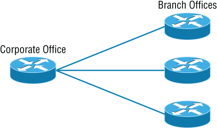
FIGURE 1.14 A point-to-multipoint network, example 1
Figure 1.15 shows another prime example of a point-to-multipoint network: a college or corporate campus.
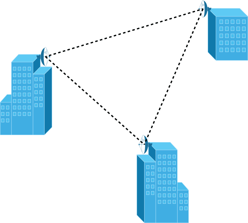
FIGURE 1.15 A point-to-multipoint network, example 2
Hybrid Topology
I know I just talked about the hybrid network topology in the section about mesh topology, but I didn't give you a mental picture of it in the form of a figure. I also want to point out that hybrid topology means just that—a combination of two or more types of physical or logical network topologies working together within the same network.
Figure 1.16 depicts a simple hybrid network topology; it shows a LAN switch or hub in a star topology configuration that connects to its hosts via a bus topology.
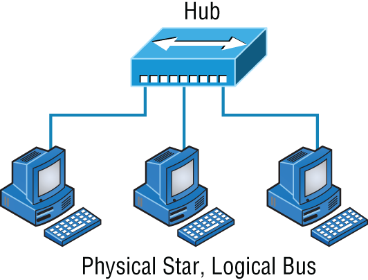
FIGURE 1.16 A simple hybrid network
Topology Selection, Backbones, and Segments
Now that you're familiar with many different types of network topologies, you're ready for some tips on selecting the right one for your particular network. You also need to know about backbones and segments, which I'll cover in the very last part of this chapter.
Selecting the Right Topology
As you now know, not only do you have a buffet of network topologies to choose from, but each one also has pros and cons to implementing it. It really comes down to that well-known adage “Ask the right questions.” First, how much cash do you have? How much fault tolerance and security do you really need? Also, is this network likely to grow like a weed—will you need to quickly and easily reconfigure it often? In other words, how scalable does your network need to be?
For instance, if your challenge is to design a nice, cost-effective solution that involves only a few computers in a room, getting a wireless access point and some wireless network cards is definitely your best way to go because you won't need to part with the cash for a bunch of cabling and it's super easy to set up. Alternatively, if you're faced with coming up with a solid design for a growing company's already-large network, you're probably good to go with using a wired star topology because it will nicely allow for future changes. Remember, a star topology really shines when it comes to making additions to the network, moving things around, and making any kind of changes happen quickly, efficiently, and cost effectively.
If, say, you're hired to design a network for an ISP that needs to be up and running 99.9 percent of the time with no more than eight hours a year allowed downtime, well, you need Godzilla-strength fault tolerance. Do you remember which topology gives that up the best? (Hint: Internet.) Your primo solution is to go with either a hybrid or a partial mesh topology. Remember that partial mesh leaves you with a subset of n(n–1)/2 connections to maintain—a number that could very well blow a big hole in your maintenance budget!
Here's a list of things to keep in mind when you're faced with coming up with the right topology for the right network:
- Cost
- Ease of installation
- Ease of maintenance
- Fault-tolerance requirement
- Security requirement
The Network Backbone
Today's networks can get pretty complicated, so we need to have a standard way of communicating with each other intelligibly about exactly which part of the network we're referencing. This is the reason we divide networks into different parts called backbones and segments.
Figure 1.17 illustrates a network and shows which part is the backbone and which parts are segments.
You can see that the network backbone works similar to how a human backbone does. It's what all the network segments and servers connect to and what gives the network its structure. As you can imagine, being such an important nerve center, the backbone must use some kind of seriously fast, robust technology—often Gigabit Ethernet. And to optimize network performance—its speed and efficiency—it follows that you would want to connect all of the network's servers and segments directly to the network's backbone.
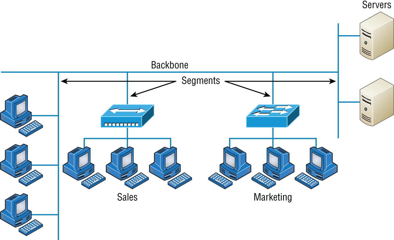
FIGURE 1.17 Backbone and segments on a network
Network Segments
When we refer to a segment, we can mean any small section of the network that may be connected to, but isn't actually a piece of, the backbone. The network's workstations and servers organized into segments connect to the network backbone, which is the common connecting point for all segments; you can see this by taking another look at Figure 1.17, which displays four segments.
Service-Related Entry Points
In the networking world, there are clearly defined boundaries where one entity hands off a connection to another. These are common when connecting to a service provider's or carrier's WAN circuit. The service entry point defines the point of responsibility. The common term used is the demarcation point, or demarc for short. A carrier will usually terminate with a piece of equipment called a smart jack that allows them to run diagnostics up to the physical point where the customer’s network connects.
Service Provider Links
Service providers are Internet service providers and cable and telephone companies that provide networking services. There are many different technologies used to provide these services such as satellite links for earth station to satellite connections.
Traditional telephone companies may have extensive copper connections to homes and businesses that use Digital Subscriber Lines, or DSL, to provide last hop high speed digital services. DSL used to be a popular method to connect to the Internet and a solid alternative to cable or fiber connections.
Cable companies now offer data and Internet services over their hybrid fiber/coax networks in additional to their traditional video offerings. A cable modem is installed at the customer's site and provides data, video, and voice services off the cable network.
Another common link is the leased line. When the provider installs a leased line, it is either a copper or fiber termination that interconnects two endpoints and is exclusive to the customer; there is no shared bandwidth and leased lines are very secure as they are dedicated for the customer's use.
As you learned earlier in this chapter, a MAN uses optical; it is sometimes referred to as metro optical network instead of a MAN.
Virtual Networking
Just as the server world has been moving to virtualized processes, so has the network world. It is now common to provide networking services without deploying a hardware switch or router; it is all done in software! Companies such as VMware offer virtual switch (vSwitch) technology that provides the Ethernet switched and routing functions on the hypervisor, eliminating the need for external networking hardware. A vSwitch can operate and be configured the same as an external hardware appliance; just remember, a vSwitch is similar to software virtualization.
Virtualized servers do not have the means for inserting a hardware network interface card since they only exist in software. A virtual network interface card (vNIC) is installed to connect the virtual device to the hypervisor, and from there, out to the LAN.
Network function virtualization (NFV) is the process of taking networking functions such as routers, switches, firewalls, load balancers, and controllers and virtualizing them. This process allows all of these functions to run on a single device.
The magic behind all of the virtual networking popularity is the hypervisor. The hypervisor is software that is installed directly on a bare metal server and allows for many virtual machines (VMs) to run thinking they are using the server's hardware directly. This allows for many servers and virtual network devices to run a on a single piece of computing hardware.
Summary
This chapter created a solid foundation for you to build your networking knowledge on as you go through this book.
In it, you learned what, exactly, a network is, and you got an introduction to some of the components involved in building one—routers, switches, and hubs—as well as the jobs they do in a network.
You also learned that the components required to build a network aren't all you need. Understanding the various types of network connection methods, like peer-to-peer and client-server, is also vital.
Further, you learned about the various types of logical and physical network topologies and the features and drawbacks of each. I wrapped up the chapter with a discussion about network virtualization and equipped you with the right questions to ask yourself to ensure that you come up with the right network topology for your networking needs.
Exam Essentials
- Know your network topologies. Know the names and descriptions of the topologies. Be aware of the difference between physical networks (what humans see) and logical networks (what the equipment “sees”).
- Know the advantages and disadvantages of the topologies. It is important to know what each topology brings to the table. Knowing the various characteristics of each topology comes in handy during troubleshooting.
- Understand the terms LAN and WAN. You need to understand when you would use a LAN and when you would use a WAN. A LAN is used to connect a group of hosts together, and a WAN is used to connect various LANs together.
Written Lab
You can find the answers to the written labs in Appendix A.
- What are the three basic LAN topologies?
- What common WAN topology often results in multiple connections to a single site (leading to a high degree of fault tolerance) and has one-to-many connections?
- What is the term for a device that shares its resources with other network devices?
- What network model draws a clear distinction between devices that share their resources and devices that do not?
- Which network topology or connection type can be implemented with only two endpoints?
- What device is generally implemented as a star topology?
- What does MPLS stand for?
- What does WAN stand for?
- Will a computer that shares no resources most likely be connected to the backbone or to a segment?
- Which LAN topology is characterized by all devices being daisy-chained together with the devices at each end being connected to only one other device?
Review Questions
You can find the answers to the review questions in Appendix B.
- You need a network that provides centralized authentication for your users. Which of the following logical topologies should you use?
- VLANs
- Peer-to-peer
- Client-server
- Mesh
- You need a topology that is scalable to use in your network. Which of the following will you install?
- Bus
- Ring
- Star
- Mesh
- Which of the following physical topologies has the most connections and is the least popular for LANs?
- Bus
- Star
- Ring
- Mesh
- In a physical star topology, what happens when a workstation loses its physical connection to another device?
- The ring is broken, so no devices can communicate.
- Only that workstation loses its ability to communicate.
- That workstation and the device it's connected to lose communication with the rest of the network.
- No devices can communicate because there are now two unterminated network segments.
- Which type of WAN technology uses labels, which enables priority of voice through the network?
- VPN
- T1
- MPLS
- LAN
- Bus
- What is a logical grouping of network users and resources called?
- WAN
- LAN
- MPLS
- Host
- Which of the following is a concern when using peer-to-peer networks?
- Where to place the server
- Whose computer is least busy and can act as the server
- The security associated with such a network
- Having enough peers to support creating such a network
- Which of the following is an example of when a point-to-multipoint network is called for?
- When a centralized office needs to communicate with many branch offices
- When a full mesh of WAN links is in place
- When multiple offices are daisy-chained to one another in a line
- When there are only two nodes in the network to be connected
- Which of the following is an example of a LAN?
- Ten buildings interconnected by Ethernet connections over fiber-optic cabling
- Ten routers interconnected by Frame Relay circuits
- Two routers interconnected with a T1 circuit
- A computer connected to another computer so they can share resources
- Which of the following is a disadvantage of the star topology?
- When a single port on the central concentrating device fails, the entire network loses connectivity.
- When the central concentrating device experiences a complete failure, all attached devices lose connectivity to the rest of the network.
- In a star topology, a more expensive type of host must be used compared to the host used when implementing a physical bus.
- It is more difficult to add stations and troubleshoot than with other topologies.
- What is a difference between a LAN and a WAN?
- WANs require a router.
- WANs cover larger geographical areas.
- WANs can utilize either private or public data transport.
- All of the above.
- Which of the following provides the most physical layout flexibility in a very large, geographically dispersed enterprise network?
- Bus topology
- LAN switch
- Star topology
- MPLS cloud network
- In what type of network are all computers considered equal and do not share any central authority?
- Peer-to-peer
- Client-server
- Physical topology
- None of the above
- What advantage does the client-server architecture have over peer-to-peer?
- Easier maintenance
- Greater organization
- Tighter security
- All of the above
- Which of the following is an example of a hybrid network?
- Ethernet switch
- Ring topology
- Bus topology
- Star topology
- You have a network with multiple LANs and want to keep them separate but still connect them together so they can all get to the Internet. Which of the following is the best solution?
- Use static IP addresses.
- Add more hubs.
- Implement more switches.
- Install a router.
- Which type of topology has the greatest number of physical connections?
- Point-to-multipoint
- Star
- Point-to-point
- Mesh
- What type of topology gives you a direct connection between two routers so that there is one communication path?
- Point-to-point
- Star
- Bus
- Straight
- Which network topology is a combination of two or more types of physical or two or more types of logical topologies?
- Point-to-multipoint
- Hybrid
- Bus
- Star
- When designing a network and deciding which type of network topology to use, which item(s) should be considered? (Choose all that apply.)
- Cost
- Ease of installation
- Ease of maintenance
- Fault-tolerance requirements