As I mentioned in the last chapter, one of the chief objections to the use of electronic flash is the stark, flat look of direct/on-camera flash, as you can see in Figure 10.1. But as flash wizard Joe McNally, author of The Hotshoe Diaries, has proven, small flash units can produce amazingly creative images when used properly.
An on-camera flash is useful for fill light or as a master flash to trigger other units; the real key to effective flash photography is to get the flash off the camera, so its illumination can be used to paint your subject in interesting and subtle ways from a variety of angles.
Of course, often, using a cable to liberate your external flash from the accessory shoe isn’t enough. Nor is the use of just a single electronic flash always the best solution; two or more units can be combined in interesting ways to sculpt with light. What we have really needed is a way to trigger one—or more—flash units wirelessly, giving us the freedom to place the electronic flash anywhere in the scene and, if our budgets and time allow, to work in this mode with multiple flashes.
Nikon shooters have long had wireless flash capabilities, ever since the creation of the Nikon Creative Lighting System, described in Chapter 9. Like the i-TTL exposure system, the Advanced Wireless Lighting (AWL) system uses pre-flashes that fire before the main exposure to transmit triggering and exposure information to external flash units that aren’t physically connected to the Z6. Depending on whether you’re using the SB-5000 or one of the older flash units, you may be able to divide multiple flash units into as many as three different “groups” (six with the SB-5000) and communicate with them using your choice of any of up to four “channels” (to avoid interference from other Nikon photographers within range of your flash units who might be using the same channel).

Figure 10.1 Direct flash is harsh and flat.
It’s not possible to cover every aspect of wireless flash in one chapter. There are too many permutations involved. For example, you can use external flash like the SB-700 or SB-5000, an SU-800 wireless trigger, or a PocketWizard-type device as the master. You may have one external “slave” flash, or use several. It’s possible to control all your wireless flash units as if they were one multi-headed flash, or you can allocate them into “groups” that can be managed individually. You may select one of four “channels” to communicate with your strobes. These are all aspects that you’ll want to explore as you become used to working with the Z6’s wireless capabilities.
What I hope to do in this chapter is provide the introduction to the basics so that you’ll have the information you need to understand the step-by-step instructions for your Speedlight using the detailed manual supplied with the unit. Once you learn how to operate the Z6’s wireless capabilities, you can then embark on your own exploration of the possibilities.
Elements of Wireless Flash
Here are some of the key concepts to electronic flash and wireless flash that I’ll be describing in this chapter:
- Master flash. The master is the flash (or other device) that commands each of the additional flashes when using Commander mode.
- Remote flashes. For wireless operation, you need at least one flash unit not mounted on the camera, in addition to the master device (which can be another flash or a transmitter unit).
- Channels. Nikon’s wireless flash system offers users the ability to determine on which of four possible channels the flash units can communicate.
- Groups. Nikon’s wireless flash system lets you designate multiple flash units in separate groups (as many as three groups, or six groups with the SB-5000). You can then have flash units in one group fire at a different output level than flash units in another group. This lets you create different styles of lighting for portraits and other shots.
- Lighting ratios. You can control the power of multiple off-camera Speedlights assigned to each group, in order to adjust each unit’s relative contribution to the image, for more dramatic portraits and other effects.
- Control system. The SB-5000, whether used alone or with other flashes, can use either the existing optical/infrared control system deployed with earlier Speedlights or the newer radio control offered with the SB-5000 flash or with the WR-R10 as a radio trigger.
Master Flash
The master flash is the commander that tells all the other units in a setup what to do, including when to fire, and at what intensity. It communicates with your Z6, and then, when the firing parameters are determined by the camera (or you, manually), passes along the information to the individual remote flash units. Your master can be one of the following:
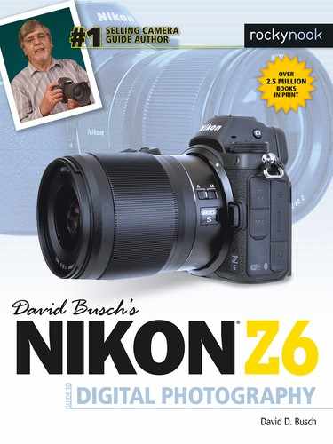
- An external flash with Commander capabilities. Use a Nikon SB-5000, SB-910, SB-700, SB-500, or compatible earlier units to communicate with the remote Speedlights using optical or, with the SB-5000, radio control. When used as a master flash, the external strobe must be physically connected to the Z6. You can mount the flash on the camera’s accessory hot shoe, or mount it on a cable, such as the SC-28 or SC-29, and then connect the other end of the cable to the Z6’s accessory shoe. (See Figure 10.2.) The master flash can be set so that it does or does not contribute to the exposure, although, because it can be used off-camera, the latter mode offers more advantages.
- The Nikon SU-800. This device is an expensive non-flash (about $340) that does nothing but serve as an optical commander for CLS-compatible flash units (see Figure 10.3). It mounts on the hot shoe of the camera and emits infrared signals (rather than monitor pre-flashes) to trigger the remote flash units. It otherwise functions exactly like a “real” master flash, communicating to groups of Speedlights over the same channels, and allowing i-TTL exposure control. It has two main uses. One application is as a commander for Nikon’s wireless “macro” lights, the SB-R200 units. In that mode, it’s ideal for any Nikon dSLR, as it serves as a trigger for models without a built-in flash, such as the Z6, Z7, D850, D810, D5, D4, D4s, D3, D3s, or D3x, and some earlier models. It’s also a more convenient close-range substitute for an attached master because it emits no light to cast shadows.
I like to use my SU-800 for off-camera flash with no need to fuss with a cable connection or camera-mounted master flash unit. The Robert E. Lee re-enactor was standing in the shade, and the diffused light was not harsh (which is the most common reason for adding flash fill.)
However, the difference in illumination between him and the background was significant, making it impossible to set an exposure that would capture both him and the flag and tent behind him (Figure 10.4, left.) I set the SB-500 to Manual exposure and 1/4 power, held it off to the left, and shot at 1/200th second and f/16 to get the photo at right. The SU-800’s infrared control has an impressive 66-foot range under these conditions (that is, not under direct sunlight). It helped me enhance the image with the off-camera flash—which provided a nice catchlight in the General’s eye—as the fill illumination.
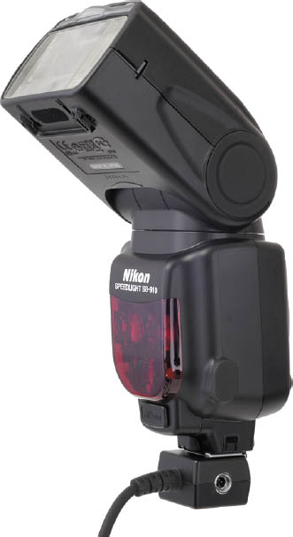
Figure 10.2 An external flash can be used as an off-camera master when connected to a cable that links it to the camera.
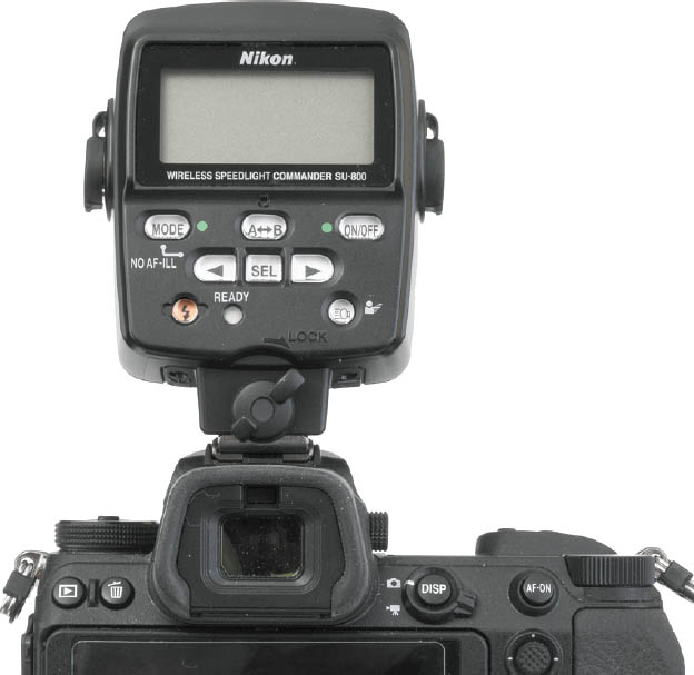
Figure 10.3 The Nikon SU-800 can serve as a master unit.
- Nikon WR-R10. When working with the SB-5000 in radio control mode, this device, plugged into the remote control/accessory connector on the side of the camera, can serve as a master controller. Unless you purchased your unit very recently, you may need to send your unit in to Nikon for a firmware upgrade to Version 3.00 to allow flash control. The firmware upgrade cannot be performed by the user. To see if your unit requires an upgrade, attach it to the Z6, navigate to the Firmware Version entry in the Setup menu, and view the WR firmware notification.
- Compatible third-party triggering devices. These include models from PocketWizard and Radio Popper. The advantage of these devices is that, unlike the optical system used by Nikon’s CLS products (limited to about 30 feet), third-party devices use radio control to extend your remote “reach” to as far as 1,500 feet or more. Their transmitters/receivers can work in concert with your own master flash, which controls the remote flashes normally when they’re in range, with the radio control taking over when the transmitter senses that the remote flash isn’t responding to the master’s instructions.

Figure 10.4 A flash can provide pleasing fill illumination outdoors in the shade.
THIRD-PARTY SOLUTIONS
I’m generally covering only Nikon-branded products in this book, because there are so many third-party devices that it’s difficult to sort out all the options. However, there are two product lines I’ve had a lot of luck with—the PocketWizard transmitters and receivers (www.pocketwizard.com) and the X-series wireless devices available from Godox (www.godox.com). These devices attach to your camera (generally by mounting on the hot shoe) and connect to your flash to allow one or more flashes to communicate with the Z6.
PocketWizard makes several products specifically for Nikon cameras, including a transmitter, which locks onto the camera’s accessory shoe (a shoe-mount flash can be mounted on top of the transmitter, if you wish). Your remote flash units can use PocketWizard transceivers. The transmitter interprets the i-TTL data from the camera and converts it into a digital radio signal to command your remote flash units. Note that this radio control system is more versatile than the pulsed light pre-flashes and infrared communications the Speedlights and SU-800 use (respectively), working through walls and in bright daylight. The PocketWizard ControlTL system switches to high-speed sync mode automatically when you choose a fast shutter speed.
Cost-conscious shooters may also want to look into the Godox X-series wireless products, available in a variety of configurations. The advantage of the Godox system is that the company offers triggers, as well as both shoe mount and studio-style electronic flash units, all compatible with Nikon’s CLS system. The Godox XProN TTL wireless flash trigger ($69) can be mounted on the Z6’s hot shoe, and used to control Nikon SB-series Speedlights (with the flash connected to the Godox X1R-N receiver [$40]). No extra receiver is required for Godox’s own shoe-mounted CLS-compatible flash units and studio flash.
Remote Flashes
To use the Advanced Wireless System, you’ll want to work with at least one remote, or slave flash unit. You can use units that are compatible with CLS or, with the (now discontinued) SU-4 accessory, other Speedlights. The remote flash for optical control can be any unit compatible with the Creative Lighting System, including the current SB-5000 and SB-700, or simpatico discontinued models, such as the SB-910/SB-900, SB-800, or SB-600. (Of these, the SB-600 can’t function as a master flash on its own.) You’ll need to set the auxiliary Speedlights to remote mode. For radio control mode, at this writing only the SB-5000 is compatible as a remote. I expect additional remote flash units will be introduced by Nikon during the life of this book.
Channels
Channels are the discrete lines of communication used by the master flash to communicate with each of the remote units. The pilots, ham radio operators, or scanner listeners among you can think of the channels as individual communications frequencies.
If you’re working alone, you’ll seldom have to fuss with channels. Just remember that all the Speedlights you’ll be triggering must be using the same channel, exactly like a CB radio or walkie-talkie. (Google these terms if you’re younger than 40.) If every flash isn’t set for the same channel, they will be unable to “talk” to each other, good buddy. I’ll show you how to adjust channels shortly.
The channel ability is most important when you’re working around other photographers who are also using the same Nikon CLS system. Each photographer sets his or her flash units to a different channel as to not accidentally trigger other users’ strobes. (At big events with more than four photographers using Nikon flash, you may need to negotiate.)
Personally, I think it’s unfortunate that Nikon was able to include only four channels when using optical control. Radio control is much more flexible; third parties with CLS-compatible systems offer many more channels. Godox, for example, provides 32 discrete channels and allows up to 99 different wireless ID settings, which makes signal interference highly unlikely no matter how many similar setups are in use simultaneously at a given venue. Radio control with the SB-5000 or WR-R10 offers just three channels (Ch5, Ch10, and Ch15), but the flash units are linked using pairing or a PIN code, which effectively increases the number of non-interfering connections. Don’t worry about Canon or Sony photographers at the same event. Their wireless flash systems use different communication systems that won’t interfere with yours.
It’s always a good idea to double-check your flash units before you set them up to make sure they’re all set to the same channel, and this should also be one of your first troubleshooting questions if a flash doesn’t fire the first time you try to use it wirelessly.
Groups
Each flash unit can be assigned to one of three groups, labeled A, B, and C. (The SB-5000 has additional groups, D, E, and F.) All the flashes in a single group perform together as if they were one big flash, using the same output level and flash compensation values. That means you can control the relative intensity of flashes in each group, compared to the intensity of flashes assigned to a different group. A group needs at least one flash unit, but can have more.
For example, you could assign one (or more) flash to Group A, and use it as the main light in your setup. Group B could be used as the fill light, and Group C designated as a hair or background light. The power output of each group could be set individually, so your main light(s) in Group A might be two or three times as intense as the light(s) in Group B (used for fill), while another power level could be set for the Group C auxiliary lights. You don’t have to use all three groups, but it is an option.
But there’s a lot more you can do if you’ve splurged and own two or more compatible external flash units. Some photographers own five or six Nikon Speedlights, including me, who has one of each model Nikon has offered, starting with the SB-800. As I mentioned, Nikon wireless photography lets you collect individual strobes into groups, and control all the Speedlights within a given group together. You can operate as few as two strobes in two groups or three strobes in three groups, while controlling more units if desired. You can also have them fire at equal output settings versus using them at different power ratios. Setting each group’s strobes to different power ratios gives you more control over lighting for portraiture and other uses.
This is one of the more powerful options of the Nikon wireless flash system. I prefer to keep my Speedlights set to different groups normally. I can always set the power ratio to 1:1 if I want to operate the flash units all at the same power. If I change my mind and need to make adjustments, I can just change the wireless flash controller and then be able to manipulate the different groups’ output as desired.
Remember that with whatever equipment you are using, outdoors if you are using optical triggering, you must have a clear line-of-sight between the master flash or SU-800 unit and sensors on the front of the slave flash units. Indoors, this requirement isn’t as critical because the pre-flash and IR signals bounce off walls and other surroundings. Radio control has a longer 98-foot (30 meter) range.
Lighting Ratios
Lighting ratios are the relative proportions of the illumination among the groups, as I just described. To get the most from the CLS system, you’ll want to understand how ratios work. That’s a topic that deserves a chapter of its own, but many Nikon Z6 owners will already be familiar with the concept. If not, there are plenty of good books and online tutorials available.
Using Ratios
When lighting a subject, you can use several electronic flash units, as shown in the highly simplified arrangement in Figure 10.5. In this case, the main flash is an external unit placed to the left of the subject, and slightly behind her. An additional flash mounted on the Z6’s hot shoe provides less intense illumination to fill in the shadows. A third flash illuminates the background, providing separation between it and the subject. All three flashes are set to the same channel, and are assigned to different groups: A, B, and C.
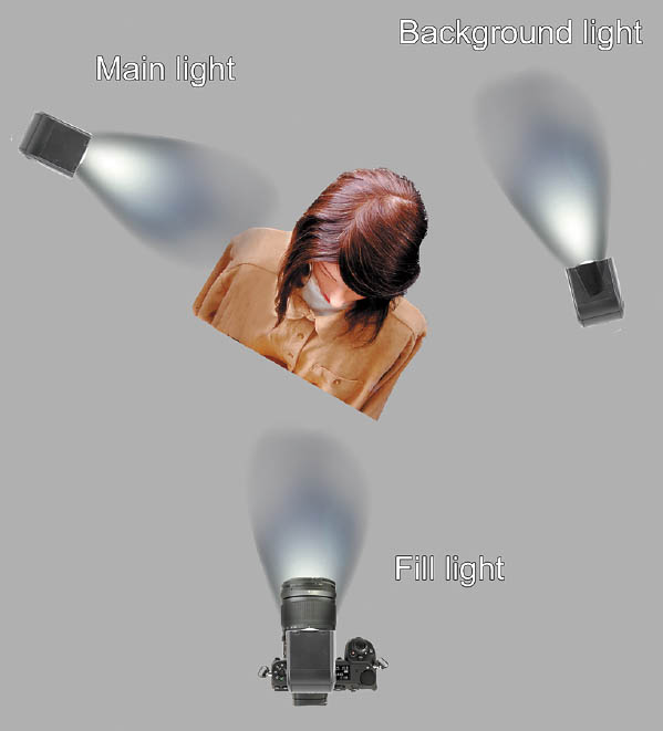
Figure 10.5 Multiple electronic flash units can be set to different intensities.
That setup makes it possible to specify Manual flash mode, in which you control the intensity of the flash, instead of TTL mode, in which the Z6 interprets the light from the preflash and adjusts output automatically. In Manual mode you can specify a different intensity to each group, with, say, the main light (Group A) firing at full power, the fill light (Group B) at 1/4 power, and the background light (Group C) at one-eighth power. The most common way to balance lights set to different power outputs is to use ratios, which are easy to calculate by setting (or measuring, with an external light meter) the exposure of each light source alone. Once you have the light calculated for each source alone, you can figure the lighting ratio.
For example, suppose that the main light for the portrait setup in Figure 10.5 provides enough illumination that you would use an f/stop of f/11. The fill light you’ll be adding is less intense, set to 1/4 power, and also located farther away from the subject (or is diffused, say, with an umbrella reflector). If the fill light produces an exposure, all by itself, of f/5.6, that translates into two f/stops’ difference or, putting it another way, the main light source is four times as intense as the fill light. You can express this absolute relationship as the ratio 4:1. Because the main light is used to illuminate the highlight portion of your image, while the secondary light is used to fill in the dark, shadow areas left by the main light, this ratio tells us a lot about the lighting contrast for the scene.
In practice, only the lighting ratio produced by illumination falling on the main subject “counts.” The light illuminating the background is just supplementary light and in most cases need not be taken into account in calculating the lighting ratio.
In practice, a 4:1 lighting ratio (or higher) is quite dramatic and can leave you with fairly dark shadows to contrast with your highlights. For portraiture, you probably will want to use 3:1 or 2:1 lighting ratios for a softer look that lets the shadows define the shape of your subject without cloaking parts in inky blackness.
If you use electronic flash equipped with a modeling light feature (or incandescent lighting), you will rarely need to calculate lighting ratios while you shoot. Instead, you’ll base your lighting setups on how the subject looks, making your shadows lighter or darker depending on the effect you want. If you use electronic flash without a modeling light, or flash with modeling lights that aren’t proportional to the light emitted by the flash, you can calculate lighting ratios. If you do need to know the lighting ratio, it’s easy to figure by measuring the exposure separately for each light and multiplying the number of f/stops difference by two. A two-stop difference means a 4:1 lighting ratio; two-and-a-half stops difference adds up to a 5:1 lighting ratio; three stops is 6:1; and so forth. Figure 10.6 shows an example of 2:1, 3:1, 4:1, and 5:1 lighting ratios.

Figure 10.6 Left to right: Lighting ratios of 2:1, 3:1, 4:1, and 5:1.
Setting Your Master Flash
Nikon’s wireless flash system gives you a number of advantages that include the ability to use directional lighting, which can help bring out detail or emphasize certain aspects of the picture area. It also lets you operate multiple strobes and establish lighting ratios, as described above, although most of us won’t own more than two Nikon Speedlights. You can set up complicated portrait or location lighting setups. Since the top-of-the-line Nikon SB-5000 (and former champ SB-910) pump out a lot of light for a shoe-mount flash, a set of these units can give you near studio-quality lighting. Of course, the cost of these high-end Speedlights approaches that of some studio monolights—but the Nikon battery-powered units are more portable and don’t require an external AC power source.
This chapter builds on the information in Chapter 9 and shows how to take advantage of the Z6’s wireless capabilities. While it may seem complicated at first, it really isn’t. Learning the Z6’s controls takes a lot of effort, and once you get the hang of it, you’ll be able to make changes quickly.
Since it’s necessary to set up both the camera and the strobes for wireless operation, this guide will help you with both, starting with prepping the camera. To configure your camera for wireless flash, just follow these steps. (I’m going to condense them a bit, because many of these settings have been introduced in previous chapters.) I’m going to assume that you’re using an external flash connected to the Z6 as a master strobe. I’ll use the SB-5000 in the example that follows.
Setting Commander Mode for the SB-5000
If you’re using an SB-5000 as your Master flash, setting it for Commander mode for automatic, through-the-lens (TTL) exposure calculation can be done using the Flash Control entry in the Photo Shooting menu. Just follow these steps:
- 1. Mount the SB-5000 flash on the Z6’s accessory shoe and power it up. The Flash Control entry in the Photo Shooting menu is grayed out if a compatible flash unit (SB-500 or SB-5000) is not mounted and turned on.
- 2. Navigate to the Flash Control entry. As with all menu functions, you can press OK or press the right directional button to select this and the following entries.
- 3. The Flash Control screen will look like Figure 10.7, left. If you have not been using your flash as a wireless master, the Wireless Flash Options choice will be set to OFF.
- 4. When wireless flash is disabled, you can access the Flash Control Mode entry and switch among TTL, Auto external flash, Guide Number (Distance Priority Manual), Manual, and Repeating Flash. (See Figure 10.7, right.)
- Set the TTL Flash Control Mode if you want the Z6 to calculate flash exposure for the main Commander flash and remote flash units.
- Set the TTL Flash Control Mode to Manual if you want to set the output levels for your electronic flash yourself, rather than allow the Z6 to set the output automatically. (See “Lighting Ratios,” above.)
- 5. In the Flash Control screen, select the Wireless Flash Options choice, shown at left in Figure 10.8.
- 6. In the next screen, shown at right in Figure 10.8, select Optical AWL.
- 7. Next, select Remote Flash Control, as seen in Figure 10.9, left.
- 8. Select Group Flash from the screen shown in Figure 10.9, right.
- 9. You will need to specify a group, mode, and output level. Select Group Flash Options, as seen at left in Figure 10.10. If you’re working in TTL mode, the screen at right in the figure appears.
- Master Flash sets the current flash as a Commander.
- Group A, Group B, and Group C settings specify the mode of the individual groups. (Groups D and E are available in Radio control mode with the SB-5000.) Choose from TTL, AA, M, or --. If you select -- for any flash or Group, that flash or Group will not contribute to the exposure. (For example, you can set your Master Commander flash to -- and it will trigger other flashes wirelessly, but will not emit a burst during the exposure.)
- 10. Comp. The term Comp. is misleading; it actually refers to output level. In the Comp. column you can specify flash exposure compensation (for TTL mode), or flash power level (for M mode).
- 11. Channel. Specify a Channel, selecting from available channels numbered 1–4. (Not all Nikon flashes can use all four channels.)

Figure 10.7 Flash control mode.
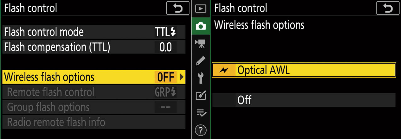
Figure 10.8 Activate Optical AWL.
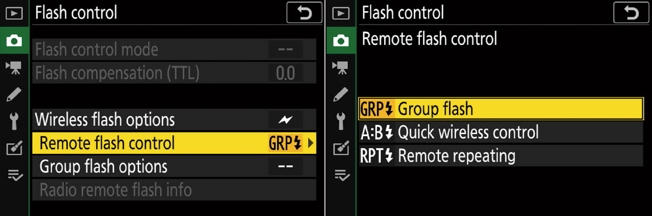
Figure 10.9 Specifying Group flash.

Figure 10.10 Setting group, mode, output level, and channel.
Wireless Flash Options
All adjustments of an SB-5000 or SB-500 mounted on the camera can be made using the Z6’s menus. And, as I mentioned earlier, SB-910, SB-900, SB-800, SB-700, and SB-600 flash can be adjusted only using the controls on the flash units themselves.
Under Wireless Flash Options, you can select three wireless modes:
- Optical AWL. Optical Advanced Wireless Lighting is the traditional wireless triggering method, available when using the SB-5000 or SB-500 flash units mounted on the camera. Radio AWL can be chosen when you have the WR-R10 unit attached to the camera’s 10-pin connector and are using a radio-compatible off-camera flash, such as the SB-5000/SB-500.
- Optical/Radio AWL. This option combines both modes, allowing you to use a WR-R10 unit attached to the camera to trigger radio-compatible flashes, and an additional compatible flash unit mounted on the Z6 to trigger non-radio off-camera flash as a Commander using Optical AWL. When the combined mode is selected, Remote Flash Control (described in the list following this one) is set to Group Flash automatically.
At this writing, the radio-controlled flash units must be SB-5000 Speedlights triggered either by another SB-5000, or by the WR-R10 transmitter mounted on the camera as a radio master. The camera-mounted optical master can be the SB-910/SB-900, SB-800, SB-700, SB-500, or SU-800 flash controller. If you’re using the SB-500 as the optical Commander/master, you must choose this Optical/Radio AWL option. You do not need to specify this option with the other flash units listed; the combined mode is activated automatically.
- Radio AWL. Note that if you want to use the SB-5000 as a radio-controlled master flash, before attaching it to your camera, you should use the flash’s controls to specify radio-controlled master flash mode, and choose group or remote repeating flash. Then, turn the flash off, attach the SB-5000 to the Z6, and power it up again. You will then be able to adjust the SB-5000 using the Z6’s Flash Control menu, or with the controls on the flash itself.
Under the Remote Flash Control entry (shown earlier in Figure 10.9), these are your choices:
- Group flash. I described flash Groups earlier in this chapter. This entry allows you to specify separate flash control modes and flash levels for each group of remote units. When working with Optical AWL or Optical/Radio AWL, you can select the channel flashes use to communicate.
- Quick wireless control. This option is a fast way to specify flash ratios by adjusting the balance between Groups A and B, with the exposure being determined by TTL metering. That is, the camera determines the intensity of the flash units in Groups A and B, and you specify the ratio between them, with, say, Group A twice as powerful as Group B. Flash compensation for Groups A and B can also be set to add or subtract from the TTL-metered exposure.
You can also set the output for any Group C flashes you use manually, perhaps to provide fill light. As with Group flash, if you’re using Optical AWL or Optical/Radio AWL, you can select the channel used for communication.
- Remote repeating. This option is the multi-flash version of Repeating flash, which I explained at the end of Chapter 9. It is available only when using SB-5000 Speedlights. As with the single-flash version, you can choose flash output level, maximum number of flashes (Times), and Frequency (flashes per second). As with the previous two modes, if you’re using Optical AWL or Optical/Radio AWL, you can select the channel used for communication.
- Radio Remote Flash Info. If you are using radio control, this entry appears, and the flash units currently being managed are shown.
The next step is to set up each of your off-camera flashes as a remote. That’s done using controls on the flash units themselves. I’ll get to that after I’ve explained how to set Commander modes for some other Speedlights.
Setting Commander Modes for the SB-910 or SB-900
Setting Commander modes for the SB-910/SB-900 has been greatly simplified, compared to some previous Nikon Speedlights. If you’d rather use an attached flash as the master, just rotate the On/Off/Wireless mode switch to the Master position. Figure 10.11 shows the rear controls for the SB-700, SB-5000, SB-910, and SB-900.
You’ll want to tell the SB-910/SB-900 which channel it is using to communicate with the other Speedlights. You’ll need to do this separately for each of the SB-910/SB-900 units you are working with, if you’re using more than one. Here are the steps to follow. (I recommend doing several dry runs to see how setting up multiple flashes works before trying it “live.”) The steps are almost identical between the SB-910 and SB-900 (shown at the bottom of Figure 10.11), differing primarily in the Function buttons used. In each case, the buttons numbered 1 through 3 are the first three buttons just south of the LCD panel starting from left to right.

Figure 10.11 Location of the control buttons on the SB-700, SB-5000, SB-910, and SB-900 Speedlights.
Follow these steps:
- 1. Set master flash to Commander mode. On the master flash, rotate the power switch to the Master position, holding down the center lock release button of the switch so that it will move to the Master position. (This extra step is needed because Nikon knows you won’t want to accidentally change from Master to Remote.)
- 2. Access Mode. Press the Function 2 button (Function 1 button on the SB-900) to highlight M on the LCD. (Note: M in this case stands for Master, not Manual.)
- 3. Select Mode. Press the MODE button and then spin the selector dial to choose the flash mode you want to use for that flash unit, from among TTL, A (Auto Aperture), M (Manual), or - -. Then, press OK.

Tip
Reminder: At the - - setting, the master flash is disabled; it will trigger the other units, but its flash won’t contribute to the exposure—except if you’re shooting very close to the subject using a high ISO setting. If an external flash is the master, try tilting or rotating the flash head away from your subject to minimize this spill-over effect.
- 4. Set Flash Exposure Compensation. Press the Function 3 button (Function 2 button on the SB-900), and rotate the selector dial to choose the flash compensation level (–3 to +3) or manual power level (1/1 to 1/128). The amount of EV correction appears at the right side of the display, opposite the master flash’s mode indicator.
- 5. Specify group. Press the Function 2 button (Function 1 button on the SB-900) to move on to the Group Selection option. Press OK to choose Group A, or rotate the selector dial to choose Group B or C, then press OK to confirm the group you’ve chosen.
- 6. Set modes for group. Once a group is highlighted, select the mode for that group. Press the MODE button and then spin the selector dial to choose the flash mode you want to use for that flash unit, from among TTL, A (Auto Aperture), M (Manual), or - -. Then, press OK.
- 7. Set Flash Exposure Compensation for group. Press the Function 3 button (Function 2 button on the SB-900), and rotate the selector dial to choose the flash compensation level for the current group as you did in Step 3. The amount of EV correction appears at the right side of the display, opposite the group’s mode indicator.
- 8. Repeat for other groups. If you’re using Group B and Group C, repeat steps 4 to 7 to set the mode and Flash Exposure Compensation for the additional groups.
- 9. Specify channel. Once the modes and compensation for all the groups have been set on the master flash, press the Function 3 button (Function 2 button on the SB-900) and rotate the selector dial to set a channel number that the master flash will use to control its groups.
- 10. Set up remote flashes. Now take each of the remote flash units and set the correct group and channel number you want to use for each of them. I’ll describe this step later.
Setting Commander Modes for the SB-700
Setting Commander modes for the SB-700 is similar in concept to the settings for the SB-910 or SB-900. The controls for the SB-700 are shown at top left in Figure 10.11. If you want to use an attached SB-700 as the master flash, follow these steps:
- 1. Set master flash to Commander mode. On the master flash, rotate the power switch to the Master position, holding down the center lock release button of the switch so that it will move to the Master position.
- 2. Choose mode. There’s a sliding switch on the left side of the SB-700. You can choose TTL, M (Manual), or GN modes.
- 3. Set Flash Exposure Compensation. Press the SEL button to select the master flash, then choose a flash compensation value/output level using the selector dial. Press OK to confirm.
- 4. Specify group. Press the SEL button to move on to the Group Selection option. Press OK to choose Group A, or rotate the selector dial to choose Group B. (Group C is not available with the SB-700.) Set the flash exposure compensation value for each group using the selector dial. Then press OK to confirm.
- 5. Specify channel. Once the modes and compensation for all the groups have been set on the master flash, press the SEL button to highlight the Channel, then rotate the selector dial to set a channel number that the master flash will use to control its groups.
- 6. Set up remote flashes. Now take each of the remote flash units and set the correct group and channel number you want to use for each of them.
Setting Commander Modes for the SB-500
Setting Commander modes for the SB-500 is similar in concept to the settings for the SB-5000. If you want to use an attached SB-500 as the master flash, follow these steps:
- 1. Mount the SB-500 on the Z6 and turn on the power. Rotate the SB-500’s power switch, located on the lower-right corner of the back of the unit, to the lightning bolt icon.
- 2. On your Z6, navigate to the Flash Control entry. Under the Flash Control entry, choose Commander mode. Select TTL flash mode in the center column, and any flash compensation in the third column (Comp.).
- 3. Specify group. In the Z6 menu, choose Group A or Group B. (Group C is not available with the SB-500.) Choose the exposure mode and flash exposure compensation value for each group using the entries in the second and third columns.
- 4. Specify channel. Once the modes and compensation for all the groups have been set on the master flash, choose a Channel. The mode indicator lamp (CMD) on the flash illuminates when settings are made on the Z6.
- 5. Set up remote flashes. Now take each of the remote flash units and set the correct group and channel number you want to use for each of them. I’ll describe this step next.
Setting Remote Modes
Each of the external remote flash units must be set to Remote mode. With the SB-5000, that’s as easy as rotating the On/Off switch to the Remote position. Then press the wireless setting button located at the 11 o’clock position above the switch and choose optical, direct remote, or radio control remote modes. (I’m covering only optical triggering here.)
Here’s how to set up the Nikon SB-500, SB-700, SB-900, and SB-910 Speedlights as remote slave flash units. Note that you don’t need to specify compensation/output level; that’s handled by the master/commander flash. You just need to set the flash to Remote, then choose Group, Channel, and Zoom head function.
- 1. Switch flash to remote mode. With the SB-900/SB-910 or SB-700, rotate the power switch to the Remote position, holding down the center lock release button of the switch so that it will move to the Remote position. If you’re using the SB-500, you’ll set remote mode in Step 2.
- 2. Select group. With the SB-500, rotate the power switch to A or B to correspond with the remote flash group you selected for the master flash. With the SB-910, press the Function 2 button (Function 1 button on the SB-900) and choose Group A with the selector dial, and press OK. With the SB-700, press the SEL button to highlight the group, then press OK. Repeat for Group B or (with the SB-900/SB-910 only) Group C.
- 3. Set channel. With the SB-500, set the remote flash channel to Channel 3 (the only one available with that unit). With the SB-900/SB-910, press the Function 2 button to highlight the channel. If you’re using the SB-700, press the SEL button until the channel is highlighted. Then, rotate the selector dial to choose the channel number. Make sure you choose the same channel number you set earlier on the master flash. Press OK to confirm.
- 4. Choose zoom head position. With the SB-910, press the Function 1 button (or the Zoom button on the SB-900 or SB-700) to highlight Zoom Head Position, and choose a zoom head setting with the selector dial. Press OK to confirm. With the SB-900 and SB-700 push the Zoom button multiple times to change zoom settings. The SB-500 does not have a zoom head.
- 5. Repeat for each remote flash. If you’re using more than one remote/slave flash, repeat steps 1 to 4 for each of the additional CLS-compatible units.
QUICK WIRELESS CONTROL
You can choose the balance between groups A and B, and set the output for Group C manually.
Radio Control
Radio control for all flashes used with Nikon dSLR and mirrorless cameras is still in its infancy. At the time I write this, only the expensive SB-5000 flash unit can be triggered by radio signals, and the only way to trigger an off-camera SB-5000 using radio control is with another SB-5000 or the Wireless Remote Controller WR-R10. So, you’ll end up spending at least $1,000 for a two-flash radio-controlled setup. Fortunately, Nikon allows you to mix optically and radio-controlled flash units. You do gain three extra groups (Groups D, E, and F, if you can afford flashes to populate them with), but only three groups (A, B, and C) can be used with Nikon’s Quick Wireless Control setup. As always, I recommend consulting Nikon’s 120-page guide to the SB-5000 if you want to sort out all the configurations and features of this complex flash. I can provide only an overview here, rather than a detailed how-to that explains all the available combinations.
TIP
As I mentioned earlier, a more affordable radio control system is available from vendors like Godox. You can purchase inexpensive receivers/transceivers (around $70) and some less pricey Godox flash units and retain TTL exposure calculation and control of the flash output levels right at the transmitter. Unfortunately, third-party solutions are updated more frequently than Nikon’s own products (the SB-700, introduced in 2010, is still a current Nikon offering), so it’s not practical to cover them in detail in a book like this. That’s why I stick to describing Nikon’s more stable product line almost exclusively.
The WR-R10 plugs into the remote/accessory port on the side of the Z6, as seen in Figure 10.12. You’ll need to set the channel for this controller to the same channel used for your SB-5000, from Channel 5, 10, or 15. Then, you’ll need to link the controller using the Wireless Remote (WR) Options entry in the Setup menu. You can connect using pairing (the most common, and easiest) or with a PIN, which is more secure and generally used only by professionals to avoid interference in environments in which there are multiple cameras being used with this same system.
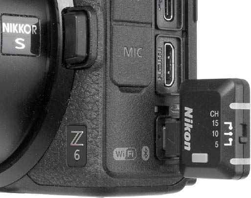
Figure 10.12 The WR-R10 plugs into the remote/accessory port.
Once you’ve set the channel on the WR-R10, press the MENU button on the SB-5000 (it’s at lower left of the unit’s back panel, as seen at upper right in Figure 10.11). Select CHANNEL, and press the right button on the SB-5000’s rotary multi selector to set the same channel as the WR-R10. Then press the OK button on the SB-5000’s multi selector.
NOTE
You must update the WR-R10’s firmware to Version 3.0 to use radio control with your SB-5000. The update cannot be done by the user; you’ll have to mail in your unit to Nikon’s repair service, as I did.
From the SB-5000’s MENU again, select Link Mode and choose either Pairing or PIN, to match the setting you specified in the Z6’s Setup menu. Press the SB-5000’s OK button to confirm. You can select PAIR>EXECUTE, and press the SB-5000’s OK button to commence pairing. Once the SB-5000 and WR-R10 have been paired, you won’t have to do it again. However, you can pair with a second WR-R10 if you have multiple cameras or multiple WR-R10 controllers.
Concurrent use of optical control and radio control is tricky. You must use a Speedlight other than the SB-5000 (such as the SB-910) as an optical master flash mounted in the hot shoe and set to trigger optically controlled remote Speedlights in Groups A, B, C, and also have the WR-R10 attached to the camera so it can trigger additional radio-controlled SB-5000 flashes in Groups D, E, and F. It’s unlikely that you’ll have such a need (or even own the appropriate flash units). This mode could come in handy if you have a complex setup and need to control some flashes at a greater distance (which radio control provides, and optical control may not).
However when using radio control, the distance between masters and remotes should be 98 feet or less. Up to 18 remote flash units can be used. Keep in mind that in radio control remote mode, the Z6’s normal Standby Timer is disabled, over-riding any setting you’ve made in the camera. It’s easy to run down your battery with extensive use, or if you forget to turn the flash or camera off.