"Any event which has not been provided with some symbol will remain fortuitous and unrepeatable."
Designers of gestural interfaces face the same problem illustrators and artists have faced for several millennia: how do you display three-dimensional movement in a two-dimensional format? Luckily for us, our tool set is broader than just paper, although paper is still our major format for documentation and will likely continue to be for some time to come.
This chapter covers documentation for those on the development team (sometimes called specifications or requirements), not for end-users, although some of the documentation can certainly be repurposed for users. Chapter 7 covers communicating to users.
A current school of thought advocates skipping documentation entirely and heading straight into prototyping. If that's your philosophy and process (and you have the team or skills to do that), simply jump ahead to Chapter 6.
Note
The difference between documentation and prototyping can be blurry. Often, one goes back and forth between them. One could also prototype first and document second if the purpose of documentation is to spell out the final design. For the purposes of this book, a prototype is an object that a user can interact with in some manner, not just view.
There are, however, good reasons for doing documentation. As Dan Brown explains in his book, Communicating Design: Developing Web Site Documentation for Design and Planning, documentation does several important things. It engenders a consistency of vision so that everyone on the project understands what is being built. It creates accountability; everyone on the project is able to see what decisions were made (and hopefully why).Finally, it creates traceability. One can determine who made decisions along the way and how. Paradoxically, the best documentation also suggests answers to questions that arise in the development or manufacturing process that aren't documented.
Designers should, however, never forget that documentation is a means to an end—a launched product—and shouldn't "fetishize" the documentation process.
Note
The amount and type of documentation that should be created should be just enough to get the product efficiently and effectively built, and exactly no more.
Several systems of documentation focus on movement. Most of these existing notation systems are far too complex for use in documenting interfaces, except perhaps for the most complicated of gestural systems. But there are some things we can extract from their methodologies.
Most of these systems of notation have sprung up around dance.Dance notation is used for the analysis and recreation of choreography, so it has similar aims as interface documentation; however, the subject (dance), the actors/users (dancers), the audience(choreographers), and the fact that there is no digital or mechanical system for the actors to interact with are some of the obvious differences.
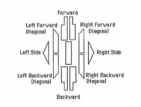
Figure 5-1. The nine different directions of Labanotation. Shadings of these symbols indicate the height of the gesture.
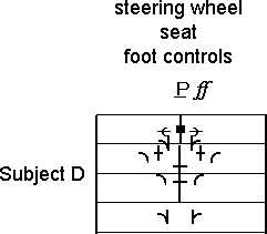
Invented in the twentieth century by dance theorist Rudolf Laban, Labanotation is a system of movement notation that is most commonly used for dance notation. Labanotation uses a set of abstract symbols to define the part of the body doing the movement, the direction and level of the movement, and the time it takes to do the movement.
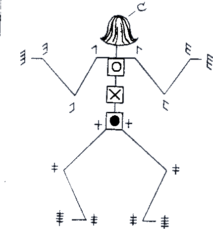
Figure 5-2. The human figure in Labanotation. The movable parts of the body are clearly called out and can be placed on a Labanotation score to help show body positioning.
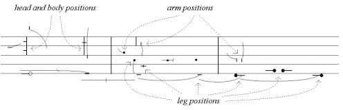
Related to Western music notation, Labanotation uses a staff of three lines on which to display its symbols. But unlike musical staves, a Labanotation staff runs vertically and is read from bottom to top. Motions that happen on the right side of the body are written on the right side of the staff and visa versa. The staff thus represents the body, with the center line marking the center of the body. The location of the symbol on the staff defines the body part it represents. Jumps, turns, spatial distance and relationships, paths of movement, and even floor plans can all be conveyed using Labanotation symbols. (Facial expressions, however, cannot be captured.[28]
Timing is displayed in two ways. Since dance is usually synchronized with music, horizontal bar lines that match the music mark overall time, and the length of a symbol defines the duration of that particular movement. Double bar lines mark the start and end of the movement score. The actor's starting position is shown before the double bar lines at the beginning of the score.

The Benesh System is another form of movement notation most frequently used for documenting choreography, particularly traditional ballet. Created by Rudolf Benesh and Joan Benesh in the late 1940s and published in 1956, the Benesh System has many similarities with Labanotation in that it uses abstract symbols on a staff to mark movement through time that can be synchronized with music. Unlike Labanotation, the staff has five lines and is read from left to right. The top of the staff indicates the top of the head, and the bottom line indicates the floor, with shoulders, waist, and knees in between.
Eshkol Wachman Movement Notation (EWMN) was created in 1958 by Noa Eshkol and Avraham Wachman. Although it is most frequently used for dance, it has also been applied to physical therapy, animal behavior, and even early diagnosis of autism. Unlike Labanotation and Benesh notation, EWMN doesn't take into account style or context (musical or otherwise).
EWMN uses a stick-figure skeleton (human or animal) as its conceptual starting point. EWMN looks at the body as a series of "limbs" that are bound by joints. For example, the forearm is a limb, with the wrist and elbow joints defining its endpoints, as is the foot between the ankle and the end of the toe. In EWMN terminology, limbs can be heavy. Heavy limbs are those that, when moved, force the lighter limbs attached to them to move involuntarily as well. Thus, moving the upper arm will also move the (relatively light) lower arm and the (even lighter) hand. Heavy limbs are relative, however. A typically light limb such as the hand can become a heavy limb if a handstand is being performed, for instance.
EWMN uses a three-dimensional sphere to plot the movements of the figure in space. Positions on the sphere can be mapped out with coordinates, similar to how positions on the globe can be indicated by longitude and latitude.
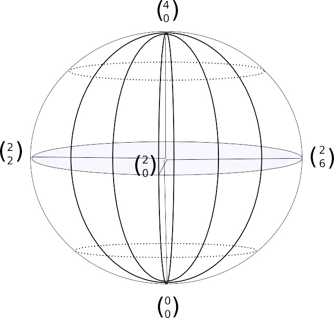
Figure 5-6. The EWMN sphere. The "North Pole" is indicated by a 4, the "Equator" by a 2, and the "South Pole" by a 0.
Unlike the other two major notation systems, the EWMN movement diagram is about as interesting to look at as a spreadsheet. Each limb has a row, and the position of the limb on the sphere is indicated by two numbers: the vertical position on top and the horizontal below. Read left to right, the stages of the action (i.e., time) are indicated by double lines, whereas the direction and amount of the movement are indicated by arrows and the number next to the arrow, with each number indicating a 45-degree change. For example, a ↑2 would mean to raise the limb 90 degrees.
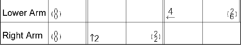
Figure 5-7. An example of EWMN, showing raising an arm that was pointing down, then bringing the forearm close to the shoulder. Courtesy Zen Faulkes.
All of the existing systems of movement notation are also notoriously painful to read and write. They require hours of time to transcribe simple movements, which is time that most designers simply don't have. Although we can draw inspiration and borrow parts from each notation system, designers of gestural interfaces will likely need lighter weight alternatives to document their work.
The importance of all of these traditional means of notation, however, is an understanding that diagramming movement is complicated and should answer some of these important questions:
What part(s) of the body are involved in the movement, and how are they positioned?
How long does the movement take to perform?
How many stages are there to the movement? What is the start point and what is the end point?
What traditional dance notation doesn't take into account is the interplay between humans and an interactive system, with which (obviously) designers and developers of gestural interfaces must be concerned. For the questions relevant to the interactive system, Victoria Bellotti and her team have devised a set of questions[29] that all documentation should address:
- Address
How do users direct communication to a system?
- Attention
How does the system establish that it is ready for input?
- Action
What can be done with the system?
- Alignment
How does the system respond?
- Accident
How does the system avoid or recover from errors or misunderstandings?
To answer these questions for interactive gestures requires a different kind of documentation, one that is informed by traditional movement notation, but is faster to produce and more easily understood by a wide variety of people—namely, the team that has to build the gestural system.
Designers and developers currently use various forms of documentation to demonstrate and specify what a product should be. Rather than throw the baby out with the bathwater, we can use this existing documentation, combined with some of the best practices of existing movement notation systems, to help document gestural interfaces.
It should be noted that no single kind of document will work for all situations; when it comes to documentation, there is no magic bullet or "one ring to rule them all," just a set of techniques that can be applied based on the needs of the system and how the team operates.
Scenarios are sketches with words. They are stories about what it will be like to use the system once it has been made and the context in which it will be used. Consider this example for a touchscreen mobile device in a theme park:
"When she purchases her entrance ticket, Lily is handed the ParkPass device. Glancing at it, she sees the main screen has a map on it and one area is blinking. She touches the blinking area, and the map zooms in and shows that a parade will take place in that part of the park in 15 minutes.She's not interested in that and instead wants to see what rides are nearby, so using a slider she zooms out from the map, then taps a button to display rides on the map. The rides appear and she taps one to select it; information about the ride, including the wait time, is then displayed."
This scenario took only a few minutes to write, but it might take hours to storyboard or wireframe, days to animate or film, and weeks to prototype.
Note
Use scenarios to rapidly sketch the final product in context for both inspiration and product definition.
One common scenario that works well is one that imagines first-time use, like the preceding example does. What happens when users encounter the gestural system for the first time? How do they know what to do and how to use it? What does it feel like to them? A scenario is a fast way to explore this, and especially since gestural interfaces can be difficult to rapidly prototype, scenarios are one way to get a rapid view of how the system will function.
Scenarios are also an excellent source for extracting tasks and features that the product will have to support.
Use cases are the dinosaur of documentation that doesn't seem to want to become extinct. But some developers swear by them and will look at few other documents. Their use is in roughing out features, specifying in plain language what a piece of functionality does and why.
Use cases begin by identifying a set of potential actors, the two most common being "the user" and "the system." For complicated gestural interfaces, one could imagine limbs and even individual sensors or input devices as actors.
Use cases have the following parts:
- Title
Give the use case a snappy, easily remembered title.It will be referenced often.
- Actors
List who or what is involved in this use case. Possible actors are the user and the system. For gestural interfaces, the user could be broken down into limbs (e.g., the hand).
- Purpose
Briefly note what this use case is meant to accomplish and why—for example, "A user wants to turn on the lights in the room."
- Initial condition
Describe the state of the system and the position of the user when the use case begins—for example, "The room is dark, and the user is in the room."
- Terminal condition
Describe the outcome once the use case is done—for example, "The lights in the room are on."
- Steps
List in order the discreet moments in this piece of functionality.
- Alternatives
List other use cases that may consider the same or similar functionality.
- Related or alternative use cases
List other use cases that are similar to or that reference this use case.
Use cases, although time-consuming and, frankly, boring, are an excellent tool for breaking down tasks and showing what the system will have to support. They do, however, suffer the same sort of issues as do scenarios, task flows, and wireframes (discussed shortly)—namely, the difficulty of explaining human gestures in words.
For gestural interfaces, the most important parts of a use case are the initial and terminal conditions. Developers will make good use of those when determining the pattern for identifying when a gesture has begun and when it has ended.

A task analysis is a list of activities that the product will have to support. Tasks can be drawn from the scenarios and use cases, as well as from requirements documentation and user research.
Once there is a task analysis, it is often helpful to put those tasks into a certain order, or task flow. Task flows are typically flowcharts that illustrate the activities and decisions throughout a process.
Task flows for gestural interfaces need to show decision points and the resultant actions for both the user and the system. The logic of the system (e.g., if a user makes X gesture, then Y happens;otherwise, Z happens) can determine not only the types and kinds of sensors required, but also the number of different gestures needed to "power" the system.
Initially, a task flow might contain generic actions ("User makes a gesture") until that gesture is determined and more richly documented via a wireframe, storyboard, animation, or movie.
Wireframes are a form of paper prototype (see Chapter 6 for more on prototypes) that frequently strip down the visual and industrial design to a bare minimum so that viewers can focus their attention on the raw features, functionality, and content of a product. They explain the structure of a product in the same way that blueprints explain the structure of a building.
When they are for touchscreen systems, they are also often what designers call "pixel-perfect," meaning that the size of the objects on the wireframe matches to the pixel what will be seen on-screen. This is a good practice for touchscreens, as it prevents designers from overcrowding the screen and not leaving enough screen real estate for adequate touch targets.
Wireframes for gestural systems need to show:
- Controls
What can be manipulated and how? What happens when a user touches the screen or an object, waves a hand, points, and so forth? Where are the controls placed? Unlike web design or even software design, the placement of controls for size, ergonomics, and to prevent screen coverage (see Chapter 1) needs to be specifically mapped out in wireframes.
- Conditional objects and states
Wireframes need to define objects that change based on context. If a button cannot be tapped until an item is selected, that needs to be shown and explained. Ideally, every state that an object can be in (e.g., idle, selected, while dragged, while dropped, idle again) and the gesture that triggers that change in state should be shown.
- Constraints
This means anything with a business, legal, technical, or physical constraint that prevents an action—especially if that action seems like it would be logical to perform, but cannot be performed. Sensor constraints are important to note (e.g., "The heat sensor only detects people within 5 meters").
- Sensor settings
For free-form systems and even some projected interactive surfaces, it is important to note the setup of the sensors: their range, sphere of detection, and sensitivity. This may be difficult to determine on paper, as sensors can give a wide range of readings that can be accurately determined only via prototyping.
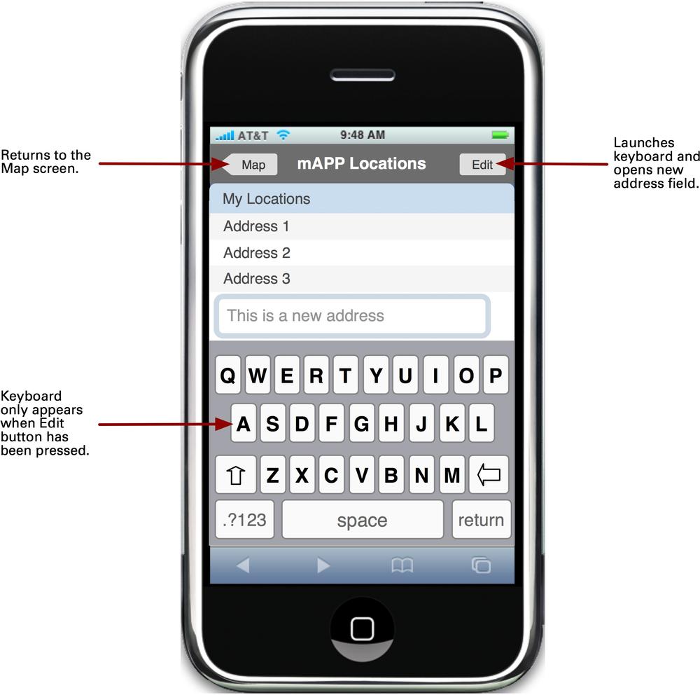
Figure 5-9. An example of a pixel-perfect wireframe for a (fake) iPhone application, built using OmniGraffle stencils created by Theresa Neil.
Describing how a product that makes use of interactive gestures works obviously requires showing how gestures engage the system. There are two ways to do this with wireframes: annotations and keyframes.
Annotations are the notes that explain pieces of functionality or controls that aren't obvious. For instance, an annotation might describe what happens when a user pushes a button or turns a dial.
Note
Use annotations to describe interactive gestures that are easy to understand, are in common use, and trigger a simple action.
There is likely no need, for instance, to document anything more complicated than noting "When the user taps this button with a finger, the device turns off." It's a simple, known gesture with a basic outcome. Any additional documentation is really overkill.
When the interactive gesture (or the triggered system behavior) is slightly more complicated, designers can use keyframes to describe them. Keyframes are a concept appropriated from classic animation, when a senior animator would draw the important moments (key frames) in a story, leaving the junior animators to "fill in" the frames in between. For instance, the senior animator would draw the anvil falling from the sky and the coyote being crushed—enough to see the major incident—but other animators would draw the in-between frames later.
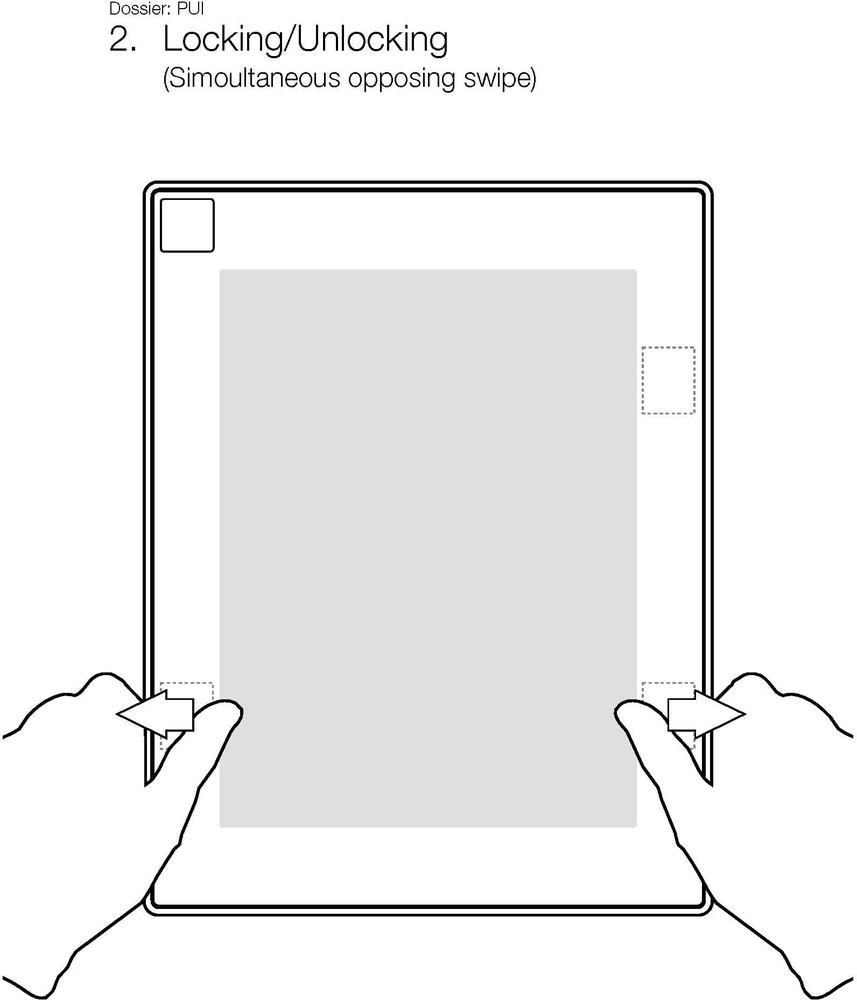
Figure 5-10. An example of a simple, single-frame keyframe, showing how this tablet device with small touchpads can be locked. Courtesy David Fisher and Plastic Logic.
Keyframes in wireframes work the same way, except that nothing is filled in between the keyframes other than, perhaps, annotations. Keyframes illustrate graphically the major moments—or even just one major moment—of an interactive gesture.
Note
Use keyframes to demonstrate something that you cannot easily describe with words but that isn't complicated enough to warrant a detailed treatment as a storyboard, movie, or animation.
Keyframes (and their accompanying annotation) should contain the answers to the questions posed by traditional movement notation: what parts of the body are involved? How long does it take to perform? What are the stages?And how does the system respond?
One framework[30] for keyframes that can work well is to illustrate the following stages for any interactive gesture (or any digital behavior, for that matter): initiation, activation, and updates. Initiation is how an action begins. What is the default state before a user initiates an action? What does the screen (if any)look like, and what does the user do to change that (e.g., touching the screen, waving an arm)? Activation is what happens while the action is going on. For example, what happens while the user is dragging an item across the screen or when a button is pushed? Updatesare what happen when the user is finished with an action. What is the state of the gestural interface once the action is complete? In other words, how does the system ultimately respond to the action?
Keyframes can also make use of traditional movement notation if the designer is so inclined. For instance, one can see Labanotation's directional key (shown in Figure 5-1) being used in conjunction with keyframes.
As more and more gestural interfaces are larger and inhabit spaces, wireframes can also indicate the environment. This can mean including the physical device form factor in the wireframe, but it can also mean the addition of indicators of height, width, sightlines, and even positions in a particular space if they are known.
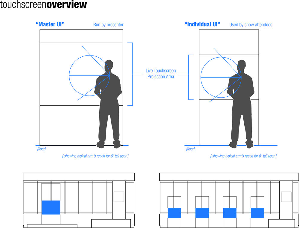
Figure 5-11. Wireframes for gestural interfaces occasionally need ergonomic, architectural-style drawings to understand the placement of the device in context. Courtesy Stimulant.
Wireframes can also function as the key document that holds all the other documents together. For instance, a wireframe annotation can note (or even directly link to) an animation of that gesture.
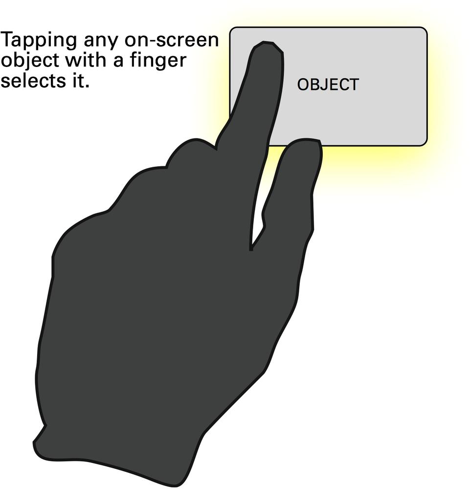
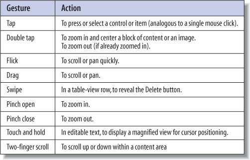
Depending on the type of system you are designing, it may be helpful to have a paper document that provides an overview of the gestures that apply to the whole system and the rules that apply to them, thus outlining the basic gestural vocabulary of the system. If, for instance, a tap on the screen always selects an item, that could be called out as a module that applies across the whole system instead of cluttering up wireframe after wireframe.
Note
Use gestural modules to document common gestures in use across the whole system.
Gestural modules work well with wireframes, and indeed can be made part of the wireframes or stand alone as their own document. For simple systems, it might be the only document you need.
If an interactive gesture is complicated or is difficult to understand out of context, a storyboard might be the best way to document it. Storyboarding is a technique borrowed from movies and comic books whereby illustrations or still photographs are used to tell a story as a sequence of images, often with accompanying text. For our purposes, the story can be short (simply displaying step by step a gesture and the resultant action), or it can be long, showing more context and narrative.
Note
Use storyboards to show detailed gestures, a sequence of gestures, or context.
Storyboards can be time-consuming to create, but not necessarily so. A sequence of stick figures or a set of crudely drawn hands can often convey gestures much more usefully and easily than any other method.
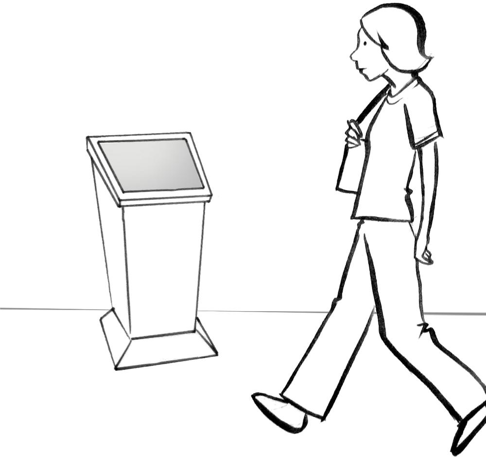
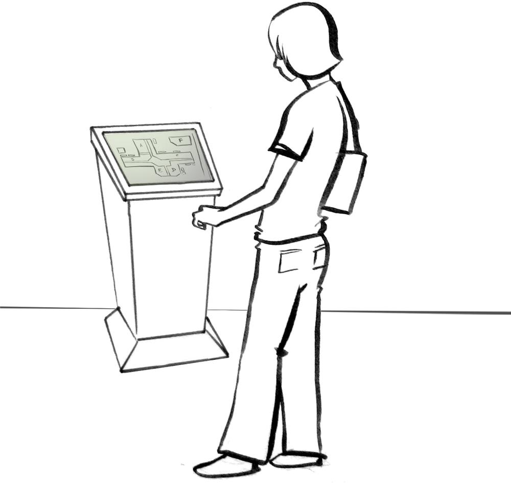
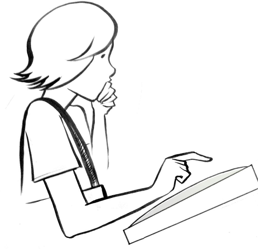
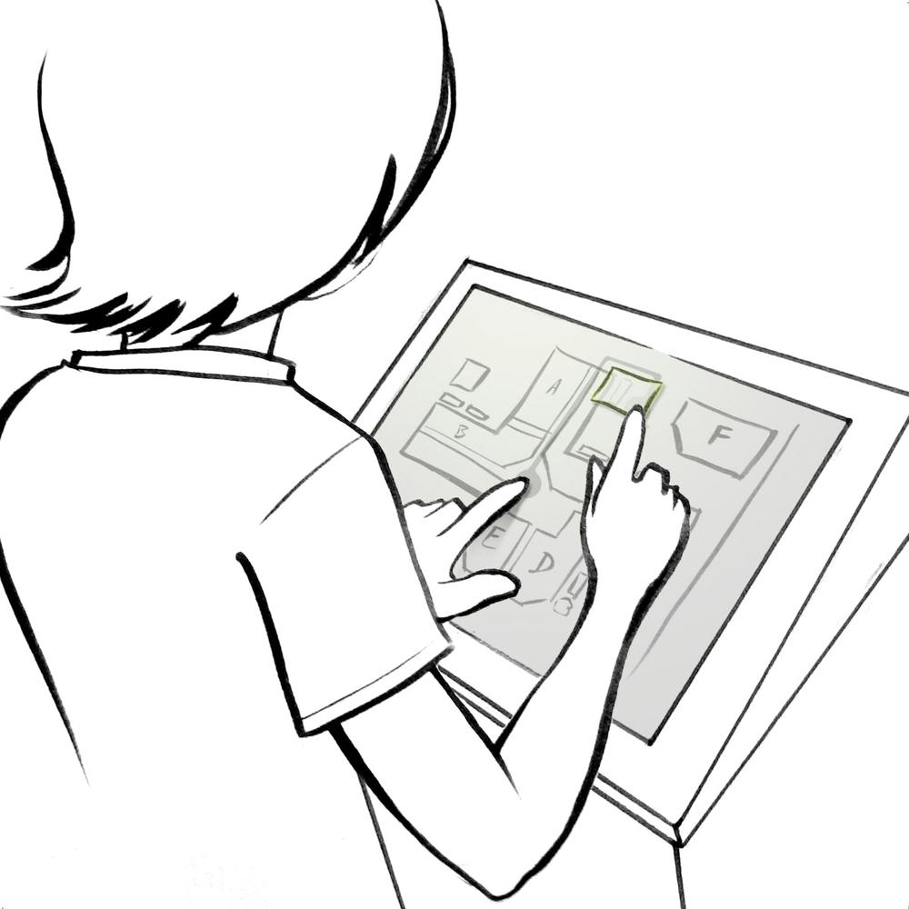
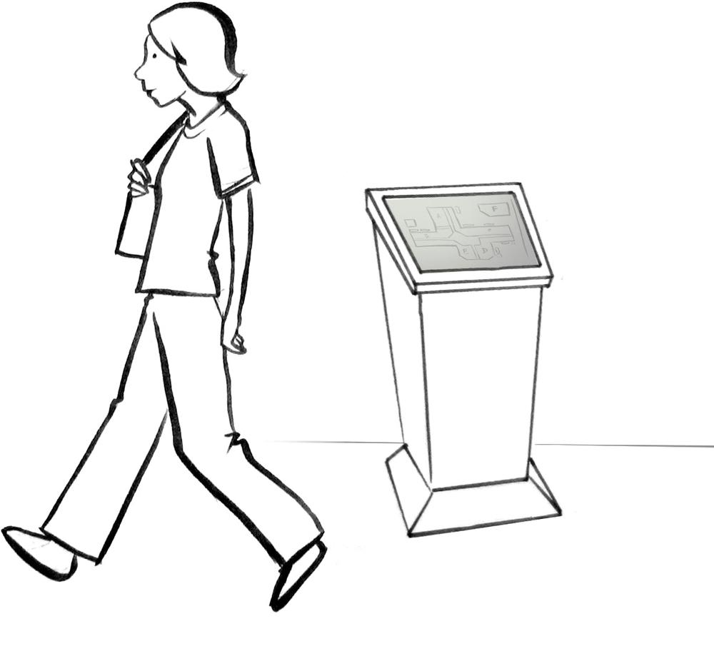
Figure 5-14. A drawn storyboard for a kiosk with a map. Note the scenes of initiation, activation, and update.
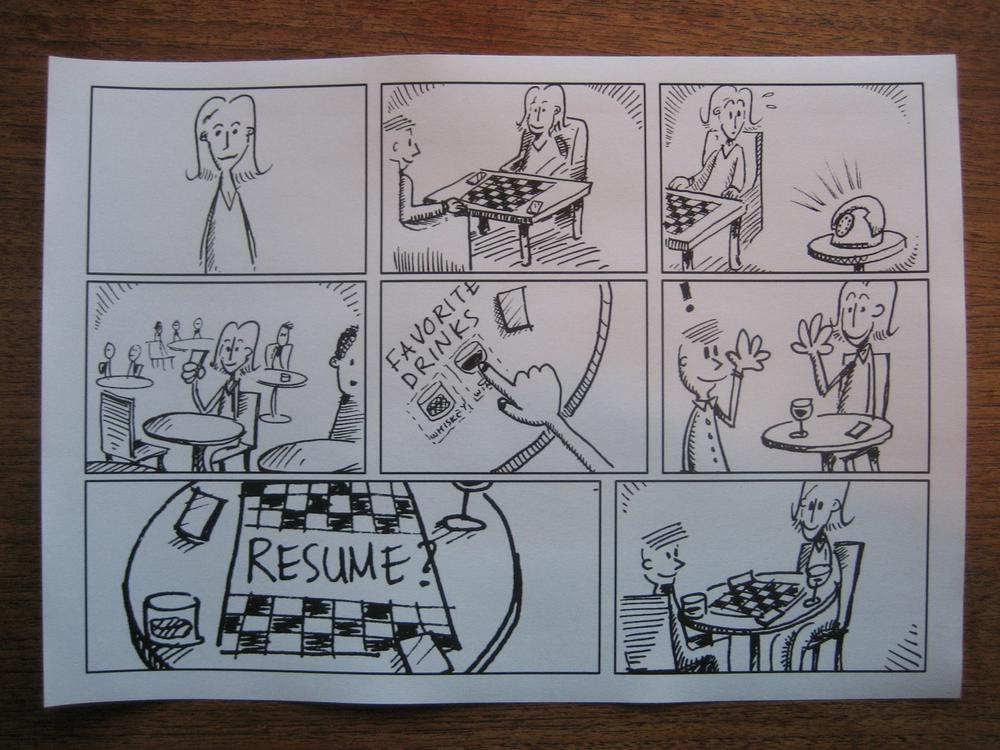
Figure 5-15. This storyboard of an interactive table tells more of a story and is more contextual, and thus more conceptual. Courtesy Kars Alfrink and InUse.
If you can't draw or if the gestures are simply too difficult to convey usefully in sketches, a set of photographs can also provide the images for a storyboard, often with very little work.
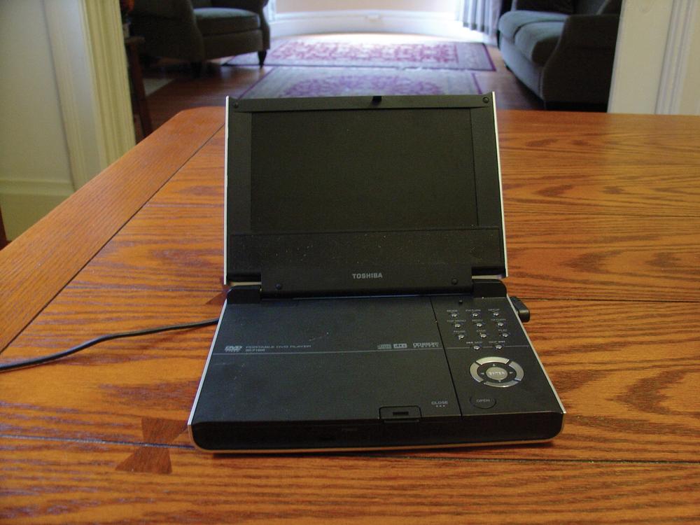
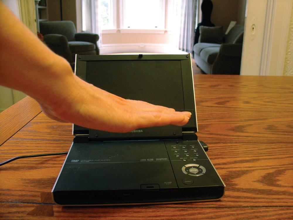
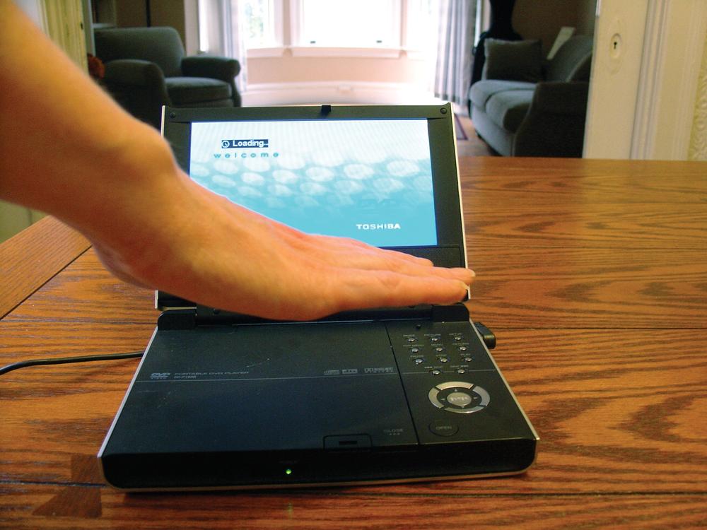
Figure 5-16. A storyboard for turning on a portable DVD player via a gesture, made up of quick snapshots.
Storyboards can also be combined with other alternative views of the gesture into what is called the swim lanes framework. Swim lanes show an overview of a scenario from several different perspectives on one sheet of paper.
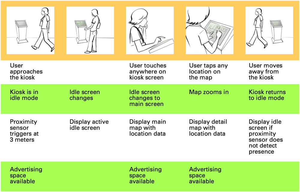
Figure 5-17. Swim lanes get their name because they are shaped like a lap pool when viewed from above.
The different views can be almost anything, but the ones that are commonly shown are:
- Top lane
The storyboard itself, including narrative
- Second lane
On-screen changes
- Third lane
System flow
- Bottom lane
Business processes
Another use for swim lanes is to combine their display with the interaction analysis framework created by Lucy Suchman in her seminal study of copy machines.[31] Suchman suggested a way to document interactions with devices that showed four things: actions not available to the machine (e.g., those performed by the user), actions available to the machine (i.e., what it can do in response to human action), effects available to the user (i.e., the system feedback and the next possible steps), and the design rationale for these items. This framework would fit well into swim lanes.
Thus, storyboards, especially when integrated into a swim lanes overview, can be a powerful and detailed way to document gestures—perhaps the most powerful because they document the gesture in context and detail the effects the gesture has on the system. But what storyboards (and wireframes)cannot easily show (because of their static, 2D nature) are flow and timing. For those, other tools are required: animations and movies.
Since timing is often a key factor in gestures, one way to demonstrate timing is via animations. An animationis a representation of a gesture in a digital format that allows for motion. Animations can be as basic as animated .gif files, or they can be more sophisticated, such as what you can create using Adobe Flash or Adobe After Effects software. Like storyboards, animations can be brief to demonstrate a solo gesture or longer to illustrate context and tell a story.
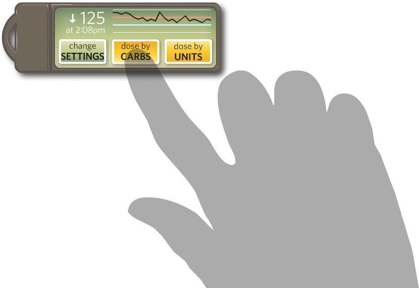
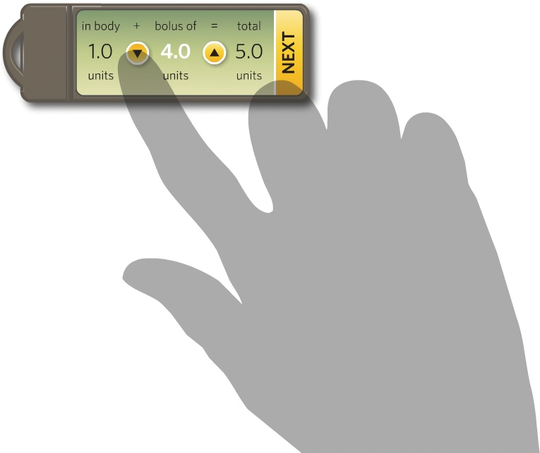
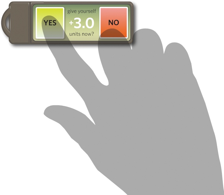
Figure 5-18. Screen captures from an animation depicting a diabetes management system.[32] The transparent hand allows for the interface to clearly show through. Courtesy Sebastian Heycke and Adaptive Path.
Obviously, one easy way to create animations is simply to place storyboard frames into a program such as Flash and have them run into each other, perhaps with a voiceover describing what is happening. This process, called animatics or previz, does give a better idea of how the product flows together, but it is more time-consuming and more difficult to mark up than paper storyboards.
The best kind of animation is that which allows viewers to run the animation uninterrupted or to pause at certain points to get more detailed information—the kind of information that would be found in an annotation.
Note
Allow for animations to pause and contain annotations at key moments.
Animations made this way can be a powerful tool for communicating gestures.
However, most animations (and movies) are not standalone documents; they simply do not have enough information density to be the sole document used by developers, manufacturers, or other designers for development and manufacturing.
Aside from the aforementioned Flash and After Effects, other software is available to facilitate creating animations:
- Pivot Stickfigure Animator
Create your own stick figure animations using your own stick figures and backgrounds. The animations can be saved as animated .gif files. For more information on this freeware software, visit http://www.geocities.com/peter_bone_uk/software.html.
- DanceForms Choreography
Create movements in a 3D environment. As the name suggests, this software, from Credo Interactive, is mainly meant for dance, but it can be adapted for interactive gestures. For more information, visit http://www.charactermotion.com/danceforms/.
- Blender
This free, open source 3D animation software is available at http://www.blender.org/.
- 3D Studio Max and Maya
These powerful (and powerfully expensive) 3D modeling and animation programs are available from Autodesk (http://www.autodesk.com/).
In theory, movies are the best way to convey gestures, as they can show a human being performing the gesture in real time and possibly in a particular context. This removes much of the ambiguity of a written description, drawings, or even animation.
Movies, however, suffer the same limitations as animations in that they are an unusual deliverable and can be time-consuming to create. It can be difficult (or at least time-consuming)to insert annotations and detail into them as well.
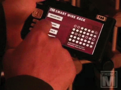
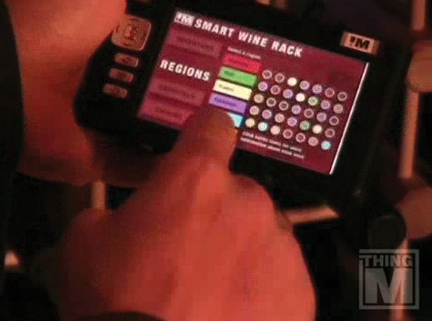
Figure 5-19. Stills from a movie prototyping WineM,[33] an RFID system for storing wine that employs a touchscreen device to manage the wine rack. This sort of single-camera scenario can convey a lot of information rapidly without too much production effort. Courtesy ThingM.
At the low end, gestural movies can be a simple, single-shot, multisecond capture done with a hand-held video camera. At the high end, they can be complete stories with multiple shots using motion capture technology. Motion capture is the digital recording of an actor's movements via sensors (usually attached to the actor's body). In a motion capture session, the actor's movements (not her visual appearance) are sampled many times per second and recorded as animation data. A computer artist then overlays that data onto a digital 3D model, causing the model to move in the same manner. The artist can then manipulate the model using computer animation software.
Motion capture is obviously going to be out of the range of all but the most sophisticated (and well-funded!) companies. Rapid, guerilla-style filmmaking with a small digital camera is much more likely, and can be accomplished in a matter of minutes if necessary. After the motion is shot, simple movie-editing software such as Apple's iMovie or Microsoft's Windows Movie Maker can be used to edit, annotate, and export the video into something suitable for documentation.
Once you have an animation or movie, the next challenge is to incorporate it into the world of traditional paper documentation since, let's face it, paper documentation is likely not going away anytime soon. The easiest way to ensure that movies and animations are used is, perhaps, to establish a website where they can be stored, viewed, and downloaded alongside other documentation. Paper documentation should contain links back to the site and, if possible, the animation or movie attached to emails sent with supporting documentation (or with documentation they support).
No matter which method or methods you choose to document your designs, it is important that the documentation allows the design to be prototyped and ultimately built. After all, as technologist David Verba pointed out,[34] few people get excited about a product from a wireframe. For that, you need a prototype, and that is the subject of the next chapter.
Communicating Design: Developing Web Site Documentation for Design and Planning, Dan Brown (New Riders Press)
Sketching User Experiences: Getting the Design Right and the Right Design, Bill Buxton (Morgan Kaufmann)
Choreographics: A Comparison of Dance Notation Systems from the Fifteenth Century to the Present, Anne Hutchinson Guest (Routledge)
Understanding Comics: The Invisible Art, Scott McCloud(Harper Paperbacks)
Physical Computing—Representations of Human Movement in Human-Computer Interaction, Astrid Twenebowa Larssen (Springer Berlin)
[28] See http://0x09.com/content/ drivel-on-movement-notation for a critique of the limitations of Labanotation.
[29] Victoria Bellotti et al. "Making sense of sensing systems: Five questions for designers and researchers." CHI 2002, ACM Press.
[30] This framework, and the importance of the term keyframes, comes from Ryan Freitas's presentation, "Beyond Wireframes: Documenting Applications," which you can download at http://www.adaptivepath.com/blog/wp-content/uploads/2006/11/ap_beyond_wireframes.pdf.
[31] See Plans and Situated Actions: The Problem of Human–Machine Communication, by Lucy Suchman (Cambridge University Press).
[32] See http://www.adaptivepath.com/charmr for more information and to watch the animation.
[33] Watch it at http://thingm.com/sketches/winem.
[34] See his presentation, "Sketching in Code," at http://uxweek2007.adaptivepath.com/slides/uxweek-slides_verba_sketching_in_code.pdf.