CHAPTER1
What Is a Network?
In this chapter, you will learn about
• The definition of the modern network and why AV professionals might want to use one
• Network classifications
• Network topologies
• Network architectures
• Networking standards and organizations
It’s easy to say this book is about networking. But what does that really mean? What is a network? Forgive what may seem like an obvious question. Computer networks have been around for so long, but have had an impact on professional audiovisual systems so recently, that it would be presumptuous to think we are all on the same page.
This chapter begins by defining a network the way information technology (IT) professionals have defined it for years. It explains why networking is so popular and why AV systems benefit from it, lays out different types of networks, and introduces you to the standard bodies that govern how networks work. For some of you this will be review; for others it will be foundational knowledge for understanding the future (and present) of AV systems design and integration.
Defining the Modern Network
A network can be made up of anything that is interconnected in a netlike manner. In the IT world, “network” is generally short for “computer network” or “data network.” From this point forward, whenever you see the word network, think in these terms: A network consists of two or more nodes interconnected so that they can share meaningful data.
Indeed, all networks have two main parts: nodes and connections. Nodes are the devices that send and receive data. In the early days of networking, a node was basically a computer. Today a node can be a computer, a mobile device, a video server, a projector, a control panel, or some other electronic system capable of sharing data.
Connections are the means by which data travels from one node to another. They can be any signal-transmission medium: radio frequency, copper cabling, light, and so on. For our purposes, passive devices, such as patch panels, also fall into this category.
But back to the network. One significant precursor to modern computer networks was ARPANET, created in 1969. ARPANET was commissioned by the Advanced Research Projects Agency (ARPA), a United States government organization dedicated to practical science and technology research (ARPA would become DARPA, the Defense Advanced Research Projects Agency).
The original ARPANET had four nodes, each of which was produced by a different manufacturer. The ARPANET project engineers had to find a way to allow four computers from different manufacturers to talk to each other simultaneously. The network they designed would eventually become the Internet.
These four computers weren’t the first electronic devices to share data over distance—people had been using telephones and fax machines for years. ARPANET’s revolutionary feature was packet switching, as opposed to circuit switching. Packet switching was a new technology that allowed several devices to use the network at the same time.
A circuit-switched network sends data in a continuous stream. No other devices can use the channel while the connection is active. The public switched telephone network (PSTN) is a circuit-switched network. A dedicated connection is made between two phones. Even if no one is actually talking (i.e., no data is being sent), no one else can use that channel. Circuit-switched networks provide reliable, dedicated links. But if you have a large number of devices that need to communicate with each other, circuit-switched networks are inefficient.
By dividing data into smaller chunks, or packets, several nodes can send information on the same channel at the same time. No single device can monopolize the connection. Put another way, a circuit-switched connection is like a railroad between two cities. A train (data) can travel from one city to the other, but nothing else can use the railroad at the same time. A packet-switched connection is like a highway with many on- and off-ramps. Cars (packets) of various sizes can get on and off the highway at different points. See Figure 1-1 for help visualizing the difference between circuit-switched and packet-switched networks.
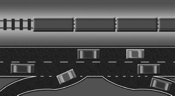
Figure 1-1 Circuit-switched networks are like a train (top); packet-switched networks resemble a highway.
 NOTE Circuit switching is a method of data transmission in which a dedicated communication channel is established between any two nodes prior to data transmission. Packet switching is a method of data transmission in which data is divided into small individual units (i.e., packets) before it is transmitted.
Why Use a Network?
The audiovisual industry has been successfully integrating systems for years without the benefit of packet-switched networks. So why have such networks become so popular and important to the commercial AV market?
When surveying networking technology from the viewpoint of traditional AV systems, networking presents potential disadvantages. For example, if there is no existing network infrastructure in a facility over which an AV system might communicate, up-front installation costs can be high. In general, pulling new wire and fiber-optic cabling throughout an existing building, office, school, or church can be expensive. Moreover, managing an AV network requires trained specialists, adding more cost. And if the network connects to the Internet, it has to be extra secure. Suddenly you have an AV system—which longtime professionals in and around the AV industry thought they understood well—that needs to be protected from things like worms, viruses, and malware. Neglected, that networked AV system can provide an avenue for hackers and malcontents into an organization’s mission-critical data.
Today, however, most organizations already have existing network infrastructure, as well as the staff or resources to support it. The capacity of modern packet-switched networks is such that you can transport a lot more data over a single cable than you can by any other signal transportation means. Packet-switched networks are flexible and scalable. A well-designed network will grow as an organization’s data and communication needs grow. It lets the organization share resources among devices. In the long run, networking can actually lower overall operating costs and boost productivity. Plus, networked devices enable rich, often real-time, face-to-face communication across vast distances. When you think about it, this is really what the AV industry is all about.
 NOTE Using existing data infrastructure may be easier said than done. Depending on the technologies employed, you may have to replace some networking equipment in order to integrate the AV system. You will learn more about network infrastructure technologies and AV-specific network protocols in later chapters.
Network Classifications
When people refer to networking today, they’re usually talking about a small subset of networks: packet-switched data networks, primarily those that use Ethernet and Internet Protocol technology. Even within that narrow definition, there are different types of packet-switched networks, including local area networks (LANs), wide area networks (WANs), campus area networks (CANs), metropolitan area networks (MANs), personal area networks (PANs), and others. Some are readily applicable; others are really buzzwords that describe uses of the most common network classifications (and the only two that really matter): LANs and WANs. It’s important to distinguish between network types so you can understand, for example, where a LAN ends and a WAN begins. Here we describe the basic network classifications that define most operational networks.
Local Area Networks
As noted, geography isn’t a useful way to classify networks. Networks are better classified according to how their nodes communicate. Data sent across a network must be sent to an address. That address is either physical or logical. Networks are classified according to whether nodes use physical or logical addresses to communicate.
LANs use physical addresses to communicate. The physical address is the media access control (MAC) address, which is hard-coded into each network interface card (NIC). MAC addresses are unique—no other device on the planet should have the same MAC address as your video server or laptop.
Data sent across a LAN is addressed to the MAC address of a device on that LAN. A node sends the packet. A network switch receives the packet and examines the MAC address to which it’s addressed. The switch then forwards the packet to the device that matches the MAC address. Figure 1-2 shows a simple LAN diagram.
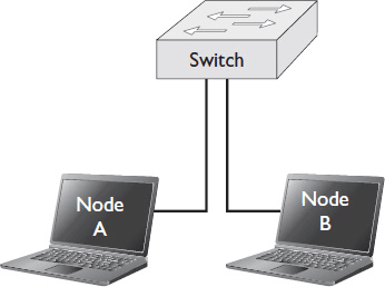
Figure 1-2 A simple LAN.
 NOTE MAC addresses are unique identifiers. Two devices having the same MAC address would be like two people having the same fingerprints. However, it’s not unheard of. When two devices on the same LAN have the same MAC address, the switch doesn’t know which node should receive which communications. Messages intended for one node may go to either, both, or neither. Always document the MAC addresses of all devices in an AV network—both to coordinate with IT stakeholders and to avoid hard-to-troubleshoot errors.
LANs are usually privately owned and operated. They are fast and high capacity. They require devices to be directly connected. This requirement effectively limits their geographical size. You can send an electrical signal only so far before it degrades beyond use.
Wide Area Networks
A WAN is a network that connects one or more LANs together. WANs use logical addresses to communicate. The form a logical address takes depends on the type of WAN. However, for the purposes of this book—and in the case of most modern WANs—the logical address is an Internet Protocol (IP) address. An IP address is assigned to a device, either manually or automatically. It may be permanently assigned, or it may change over time. It may or may not be unique.
The nodes on a WAN are routers. If a LAN is connected to other networks via a WAN, a router sits at the top of its network hierarchy. Any data that needs to travel to a device outside the LAN gets forwarded to the router. The router strips the packet of identifying LAN information, such as the MAC address of the originating device, before forwarding the packet to its intended IP address. This protects the devices on the LAN.
A WAN can be any size. It may connect two LANs within the same building or span the globe. Think of the Internet as the world’s biggest WAN.
Unlike LAN connections, long-distance WAN connections are rarely owned privately. Usually, WAN connections are leased from Internet service providers (ISPs). The speed and capacity of a WAN connection is often tied directly to how much an organization pays for it. WAN communications travel farther than LAN communications and therefore are usually slower. WANs may be slower only by a fraction of a second, but in live audio and video transmission, second fragments matter. As a result, many networked AV protocols can’t travel over WANs. Figure 1-3 shows a simple WAN diagram.
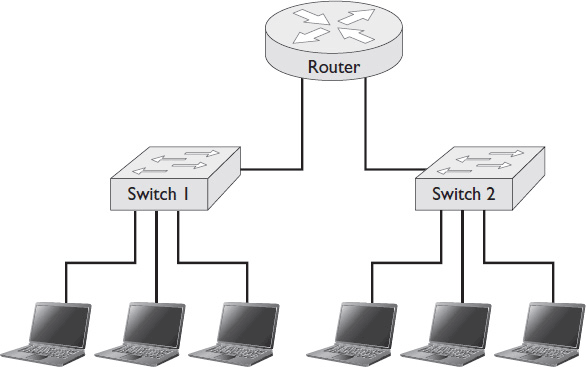
Figure 1-3 A simple WAN.
Private and Public WANs
An ISP usually owns the connection media that a WAN uses to communicate. The network itself, however, may be either public or private. ISPs provide access to the Internet, a massive public WAN.
However, ISPs also lease secure, often dedicated communication media to individual organizations. Some organizations, especially secure government entities, may even own their own long-distance communication media. Such private WANs are sometimes referred to as enterprise networks.
 NOTE The term “enterprise network” is commonly used in one of two ways: to describe the communication backbone for a large network (every node connects to the core backbone, either physically or virtually) or to describe any large, geographically dispersed private network.
Today networks of all sizes connect to a backbone in order to communicate. Even small companies are often very geographically dispersed, with offices around the world. An enterprise network or private WAN connects an organization’s resources and assets at different locations. It allows distant nodes within the same organization to communicate with far greater security than they could over the public Internet. (Although there are ways to create secure, private WANs that span the public Internet. See Chapter 10 for more information on technologies such as virtual private networks.) Depending on what you pay for it, an enterprise network may also provide superior reliability and speed.
Network Topologies
One of the most important characteristics of any network is its topology. Network topology determines how far data must travel in order to reach its destination. It determines the path that data must take as well as how many stops it may make along the way. Topology also impacts which network connections carry the most traffic. All of these factors are crucial in determining whether and how to send AV signals over a network.
All networks, including LANs and WANs, have a topology. Network topologies fall into two basic categories: physical topologies and logical topologies. A physical topology maps the physical placement of each network device and the cable installation path. Where will the devices and cables actually be located? Physical topology is constrained by the space the network equipment occupies. A logical topology maps the flow of data across a network. Which network segments and devices must data pass through in order to get from its source to its destination? Logical topology is not defined or constrained by physical topology. Two networks with the same physical topologies could have completely different logical topologies and vice versa.
LAN Topologies
When examining a local area network topology, it is important to look for single points of failure. A single point of failure is any device that, if it failed, would bring down the entire system. In a bus network, every device is a single point of failure. In a meshed or partially meshed network, there are no single points of failure.
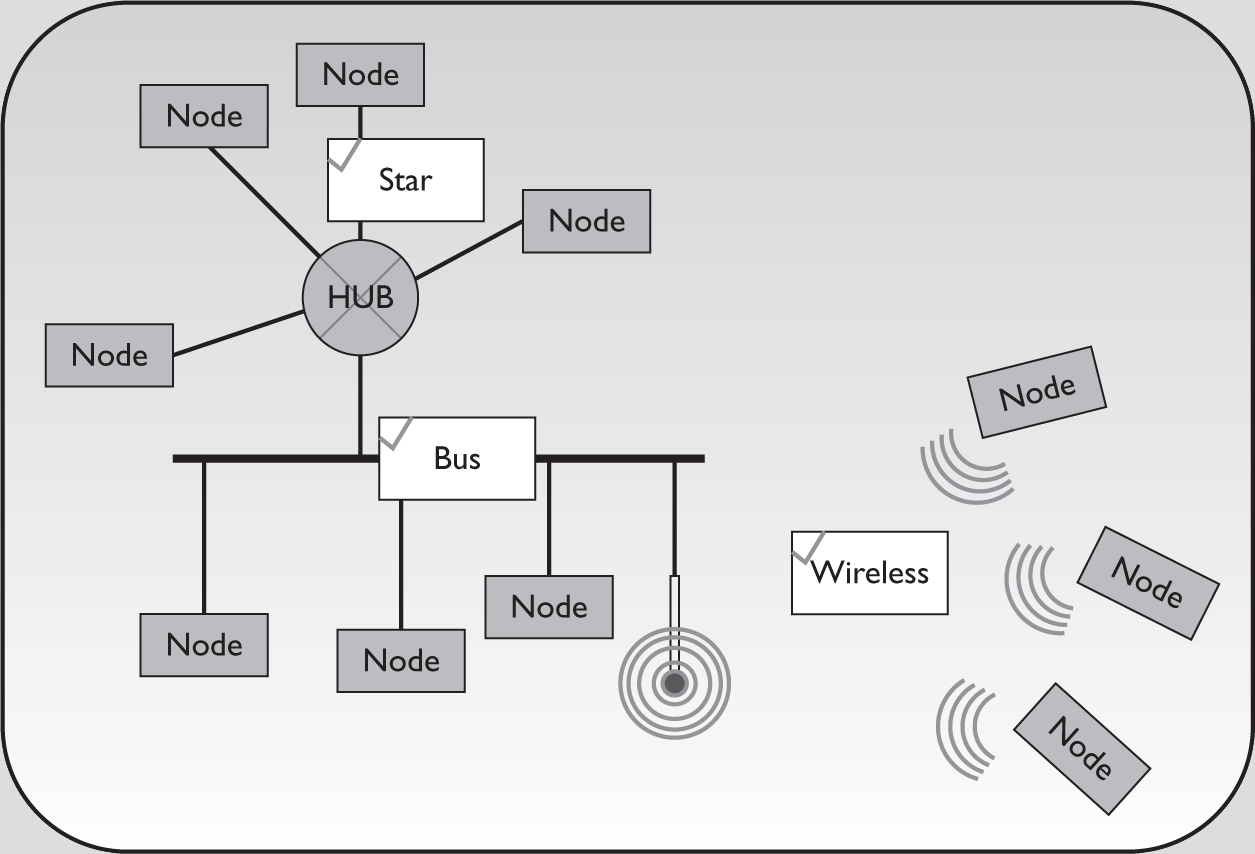
Here are some common LAN topologies. Each is pictured in Figure 1-4.
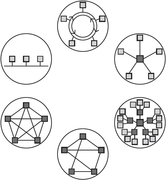
Figure 1-4 Six common LAN topologies, pictured clockwise from top: ring, star, meshed, partially meshed, extended star, and bus.
• Bus topology All nodes are connected to each other through a single cable. Data passes through each node on the cable until it reaches its destination. If any node fails, data cannot pass beyond that point.
• Ring topology Like bus topology, ring topology connects nodes in sequence, and each node in the path handles data until it reaches its destination. Instead of a single line, however, the network forms a continuous ring. In a ring network, you can create redundant paths, with data traveling clockwise and counterclockwise. That way, if one node fails, information can still flow.
• Star topology All nodes connect to a central point. This central point may be a router, switch, or hub. Star networks are hierarchical. Each node has access to the other nodes through the hub. If any node fails, information still flows. But the central device is a single point of failure; if it fails, communication stops. Star topologies are often extended to include more than one layer of hierarchy (often called an extended star topology). If any device fails, access to devices below it is cut off, but the rest of the network keeps operating. The central device, however, remains a single point of failure.
• Meshed topology Each node connects to every other node. Meshed topologies provide fast communication and excellent redundancy, ensuring that the failure of no one device can bring down the whole network. However, providing a physical connection among all devices is expensive. Therefore, fully meshed networks are rare.
• Partially meshed topology Each node connects to several other nodes but not to all. Partially meshed topologies provide good redundancy, as several devices must fail at the same time to interrupt communications.
WAN Topologies
WAN topologies also come in a few common varieties. When examining a WAN topology, it is important to identify the best place to locate shared resources. After all, sharing AV resources, such as streaming servers and multipoint control units (MCUs), is one of the major advantages of networked AV systems.
Here is a description of the common WAN topologies.
• Hub-and-spoke topology In a hub-and-spoke WAN, each LAN connects to a central location. For example, several branch offices may connect to a corporate headquarters. Like a star LAN, a hub-and-spoke WAN may have several layers of hierarchy, with hubs attaching to several spokes. With a hub-and-spoke topology, shown in Figure 1-5, shared resources should be located at the hub.
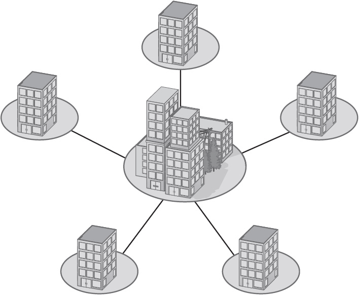
Figure 1-5 A hub-and-spoke WAN topology.
• Common-carrier topology In a common-carrier WAN, each LAN runs a spoke to an ISP backbone. With a common-carrier topology, a company may choose to lease space at an ISP and host shared resources there, or it may choose to pay for a lot of bandwidth to and from one of its sites and locate resources there. Figure 1-6 shows a common-carrier WAN topology.
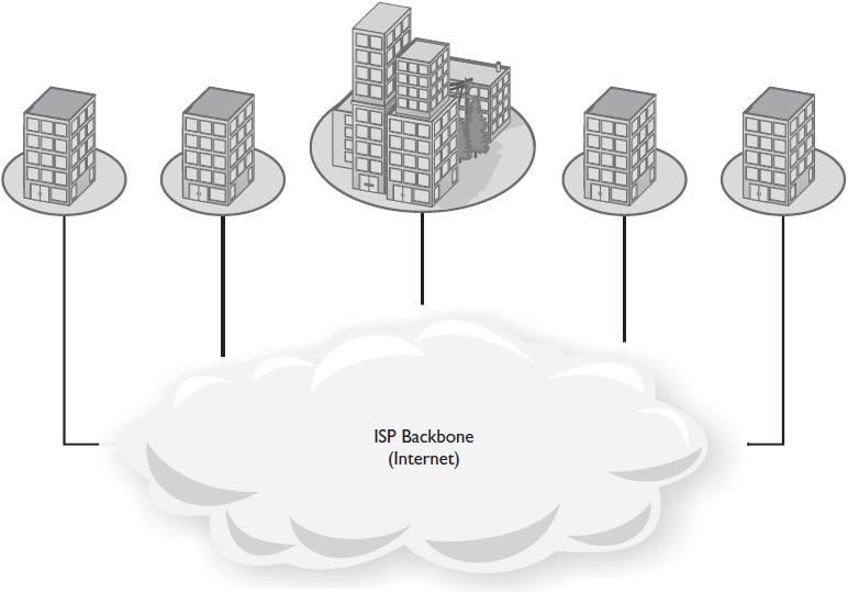
Figure 1-6 A common-carrier WAN topology.
• Meshed WAN topology In a fully meshed WAN, every LAN connects to every other LAN, providing excellent redundancy. With meshed WAN topology, resource location is generally accomplished by building a network map, including the data throughput of all connections, and locating resources “in the middle.” Figure 1-7 shows a meshed WAN topology.
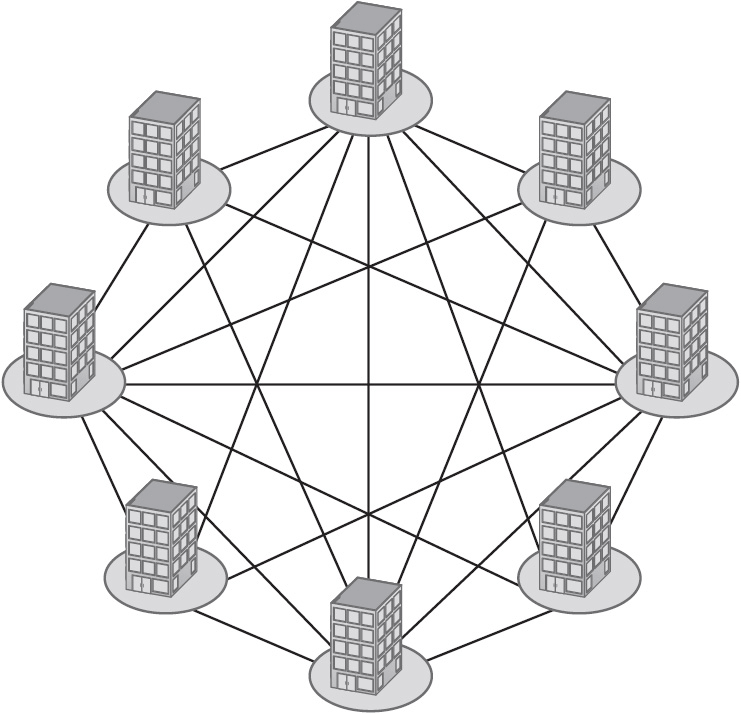
Figure 1-7 A meshed WAN topology.
Shared AV resources will ideally be stored in the same physical location as shared IT resources. In some cases, however, you may not have access to IT server closets for security reasons.
Wireless Topology
A wireless LAN (WLAN) topology is a type of physical topology. Because it uses radio frequency (RF) signals as a connection medium, a WLAN’s size and shape aren’t defined by cables. That said, a wireless topology’s size is not unlimited.
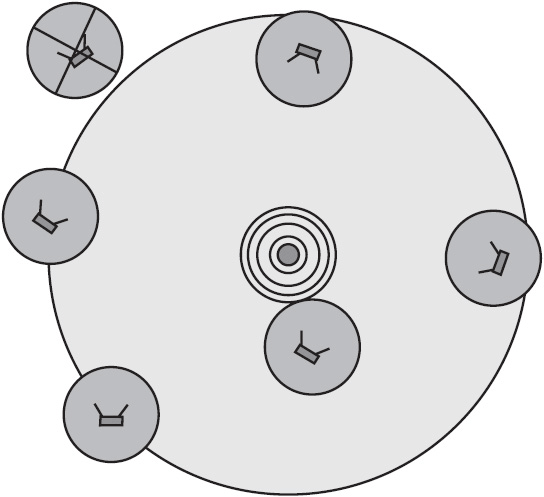
Nodes access a wireless topology through a wireless access point (WAP) instead of a physical cable. WAPs connect to each node via RF signals. The signals emitted by a wireless device—a node or an access point—form transmission lobes, which must overlap for communication to occur. With that in mind, the range and placement of devices in a wireless topology are constrained by several factors, including antenna type, signal strength, and physical obstructions to wave propagation. Figure 1-8 shows a WLAN topology where one device is out of range.
Of all physical topologies, wireless topologies create the greatest risk of exposure to outside intruders. This is because anyone can carry a wireless device into range of the WLAN. The WLAN must therefore be secured using methods such as encryption and strong authentication to ensure that no one joins the WLAN who is not supposed to.
Network Architectures
Network architecture is different from topology. Topology determines what paths data takes when devices communicate. Architecture defines what type of communication occurs, as well as the roles and interactions of devices on the network. In general, network architecture can be divided into two categories: client-server and peer to peer (P2P).
Client-Server Architecture
A client-server architecture is a two-tiered, managed architecture. The top tier of this architecture is composed of the servers; the lower tier comprises clients (personal computers or other devices). In a client-server architecture, the roles and responsibilities of client and server devices are separated and defined, with centralized management as a defining feature.
Servers provide services to clients. These services might include printing, processing power, storage, database access, and more. For example, video-on-demand servers store large video files and present them to authorized clients upon request.
A client computer runs some software through its own central processing unit (CPU), but it relies on the server to run more high-performance applications. Figure 1-9 shows a simple client-server architecture.
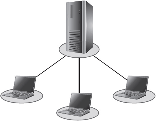
Figure 1-9 A client-server architecture.
Peer-to-Peer Architecture
In a pure peer-to-peer (P2P) architecture, there is only one level of hierarchy. All nodes act as clients and servers. Any node can request resources from or provide resources to any other node.
P2P architectures have many uses. P2P networks are often used for collaborative computing, whereby nodes borrow each other’s idle processing power, memory, and/or hard drive capacity. The scientific community, for example, uses P2P networks to solve extremely complex problems with the resources from many nodes. Instant messaging and videoconferencing applications also use P2P architectures to allow nodes to communicate directly. Figure 1-10 shows a simple P2P architecture.
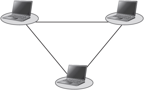
Figure 1-10 A simple peer-to-peer architecture.
Unlike a client-server architecture, the relationships between devices in a P2P architecture are unmanaged. This presents a significant security risk, especially if anyone is allowed to join the P2P group. If you have ever used a P2P file-sharing service you may have accidentally downloaded malware instead of the expected file. P2P file-sharing services are also frequently abused in order to pirate copyrighted material.
Hybrid Architectures
Hybrid architectures that incorporate both client-server and P2P architectures have become popular. Enterprise networks often allow limited peer-to-peer applications to operate on their managed client-server architectures. They recognize that they can increase productivity by allowing instant messaging, videoconferencing, distributed computing, and file sharing within their own organization. Still, they may or may not allow enterprise network nodes to join P2P groups that include nodes outside the enterprise. The risk in talking to strangers is much greater. In any case, a good risk assessment should be performed before any P2P groups are permitted.
Network Standards and Organizations
The first networks were born before there were any standards to govern how they should operate. Individual network vendors and equipment manufacturers came up with their own network card designs, wiring plans, and communication protocols.
But as networking grew in popularity—and networks grew in size—interoperability, or the ability for networking products from different manufacturers to speak a common language, became a must. Several organizations have contributed to the standardization of modern networks. Here are a few of the most important.
• The Institute of Electrical and Electronics Engineers (IEEE) creates standards relating to communications, computer engineering, computer science, electrical engineering, electronics, and information technology. The IEEE maintains IEEE 802, a family of standards for LANs and MANs. The family includes IEEE 802.3, the standard that defines Ethernet. In 1997 the IEEE published the original 802.11 standard, which governs wireless networking and provides the basis for products labeled “Wi-Fi.”
• The International Organization for Standardization (ISO) is one of the leading standard-making organizations in the world. The ISO’s primary focus is international standardization. Its greatest contribution to networking has been the Open Systems Interconnection (OSI) model (see Chapter 2). The OSI model gives developers and network engineers greater insight into how a network should function.
• The Internet Engineering Task Force (IETF) creates standards (called “Requests for Comments,” or RFCs) that apply to the Internet. The IETF cooperates closely with the World Wide Web Consortium (see following) and the ISO. The IETF maintains the Transmission Control Protocol/Internet Protocol (TCP/IP) suites, which define how data should be formatted, addressed, transmitted, routed, and received on a network. The Internet Protocol suite came out of ARPANET.
• The World Wide Web Consortium (W3C) is the international standards body for the World Wide Web. It develops standards and guidelines for advancing communication via the Internet. The W3C maintains standards for HyperText Markup Language (HTML) and Cascading Style Sheets (CSS), among others. HTML and CSS are two main ways of defining the way websites appear in web browsers.
• The Telecommunications Industry Association (TIA) develops voluntary industry standards and specifications for telecommunications equipment and fiber-optic products. TIA co-authored EIA/TIA 568 standards, which define Ethernet copper cabling and the proper wiring of Ethernet connectors.
 NOTE InfoComm International is an American National Standards Institute (ANSI) accredited standards developer (ASD). ANSI is the official US representative to the ISO and promulgates standards across a wide variety of industries, including AV.
Although it does not specifically develop networking standards, InfoComm creates standards that improve the performance of AV systems. There are currently five ANSI/InfoComm standards, governing acoustics, AV systems design processes, projected video, energy management, and AV systems verification or commissioning. For more information, visit infocomm.org/standards.
Chapter Review
A network can be a lot of things. You should now understand that, for the purpose of this book, a network is a packet-switched IT network, based primarily on Ethernet and IP technology. You have learned ways to describe networks according to classification, topology, or architecture. This is foundational information for successfully partnering with IT departments and deploying networked AV systems.
Now that you’ve read this chapter, you should be able to
• Identify the characteristics and advantages of a packet-switched network
• Classify a packet-switched network according to geographical layout
• Differentiate between network topologies and identify single points of failure
• Distinguish between client-server and peer-to-peer networks
• Identify important networking standards and standards organizations
Review Questions
1. A wide area network (WAN) uses _____ to send information between nodes.
A. logical addresses, such as IP addresses
B. peer-to-peer addresses, such as instant message addresses
C. client-server addresses, such as server names
D. physical addresses, such as MAC addresses
2. In order for a node to access a wireless network, the node must be within ____.
A. the same horizontal plane as a wireless access point
B. 90 degrees off axis from the wireless access point’s antenna(e)
C. the same room as a wireless access point
D. a wireless access point’s transmission lobe
3. In a _____ topology, every node on the network can access every other node through a central device.
A. bus
B. ring
C. star
D. meshed
4. In a _____ WAN topology, all LAN sites connect to an ISP backbone.
A. hub-and-spoke
B. common-carrier
C. star
D. meshed
5. In a client-server architecture, the top tier of the network hierarchy is occupied by _____, which provide services to the lower tier.
A. servers
B. switches
C. clients
D. nodes
6. A _____ uses unique, hard-coded physical addresses, known as media access control (MAC) addresses, to send data between nodes.
A. personal area network (PAN)
B. local area network (LAN)
C. global area network (GAN)
D. wide area network (WAN)
7. A(n) _____ network forms a dedicated channel between two nodes and sends data in a continuous stream.
A. packet-switched
B. circuit-switched
C. Internet Protocol (IP)
D. Ethernet
8. _____ topology provides the best possible redundancy, but is so expensive that it’s rarely used.
A. Ring
B. Extended star
C. Fully meshed
D. Partially meshed
9. In order to determine the location of network infrastructure and hardware, you should examine the network’s _____.
A. physical topology
B. communication method
C. logical topology
D. architecture
Answers
1. A. A wide area network (WAN) uses logical addresses, such as IP addresses, to send information between nodes.
2. D. In order for a node to access a wireless network, the node must be within a wireless access point’s transmission lobe.
3. C. In a star topology, every node on the network can access every other node through a central device.
4. B. In a common-carrier WAN topology, all LAN sites connect to an ISP backbone.
5. A. In a client-server architecture, the top tier of the network hierarchy is occupied by servers, which provide services to the lower tier.
6. B. A local area network uses unique, hard-coded physical addresses, known as media access control (MAC) addresses, to send data between nodes.
7. B. A circuit-switched network forms a dedicated channel between two nodes and sends data in a continuous stream.
8. C. Fully meshed topology provides the best possible redundancy, but is so expensive that it’s rarely used.
9. A. In order to determine the location of network infrastructure and hardware, you should examine the network’s physical topology.

