CHAPTER 2
Layers of a Network
In this chapter, you will learn about
• The Open Systems Interconnection (OSI) model, its seven layers, and how they determine the way data moves across a network
• The characteristics of Physical Layer transmission media, including copper, fiber, and wireless media
• The Physical Layer and how it pertains to networked AV systems, with specifics about twisted-pair (CAT) cabling and fiber-optic cabling
• Long-distance communication media at the Physical Layer
• The Data Link Layer, how it pertains to networked AV systems, and why AV-specific protocols are important
Now that you understand the underlying concepts of a packet-switched network, it’s time to start delving into what makes it function. In this chapter, you will learn about the layers of an IP network, as defined by industry standards bodies. We start by defining all the layers of a network, then go deeper into two layers that most affect networked AV systems: the Physical and Data Link layers.
The Physical Layer of a network describes the actual media used to transport data from one point to another—the cables and connectors. It is important to be aware of the advantages and limitations of common network transmission media so you can choose the right cables and connectors for your networked AV applications. You also need to understand what causes cables and connectors to fail so you can manage and maintain networked AV systems.
The Data Link Layer comprises protocols used to transport data from one node to another across a network. The most important Data Link Layer technology is Ethernet. In fact, it’s so important that it needs its own chapter (Chapter 6). We introduce Ethernet here and make the case for AV-specific Data Link Layer protocols, but if you want your crash course in Ethernet and related technologies right away, feel free to jump ahead.
The OSI Model
The Open Systems Interconnection (OSI) model provides a conceptual map for the transfer of data across a network. It was created in the early days of digital networking to provide a common language for technology designers and manufacturers. The OSI model can be used to describe the functions of any networking hardware or software, regardless of equipment, vendor, or application.
As the networking has matured, it has become harder to fit networking technologies into the strict categories of the OSI model. Many operate at several different layers. Still, the OSI model provides useful shorthand for discussing networking software and devices.
The OSI model defines a stack of layers to communicate or transmit data from one networked device to the next. Layers 1–3, known as the Media layers, define hardware-oriented functions like routing, switching, and cable specifications. Layers 4–5, the Host layers, define the software that implements network services. Each layer contains a broad set of protocols and standards that regulate a certain portion of the data-transfer process. A data transfer on any given network likely uses several different protocols at each layer in order to communicate.
The OSI model is often used to describe the purpose or functionality of networking protocols, software, or devices. Knowing the OSI layer(s) at which a technology operates can be useful in several ways. The OSI model can
• Tell you what a technology does, and when those events occur in the data-transfer process. For instance, Application Layer error checking occurs at the host, looking for the kinds of errors that really matter to the application. Transport Layer error checking has no awareness of the application; it just looks for any missing packets.
• Provide a road map for troubleshooting data-transfer errors. The OSI model describes the signal flow of networked data. Just as you would use a signal-flow diagram to troubleshoot a display system in a conference room, checking at each point in the path, you can troubleshoot a network by observing the data-transfer process one layer at a time.
• Indicate which service providers are responsible for each stage of data transfer. Layers of the OSI model often represent a service provider handoff. For instance, an AV technology manager may be responsible for Layer 1 and 2 devices and Layer 5–7 software, while the network manager controls all Layer 3 and 4 technology.
Layers of the OSI Model
Data is sent across a network by applications. This means that when a computer sends a message, the message starts at Layer 7, the Application Layer, and moves down through the OSI model until it leaves the sending device on Layer 1, the Physical Layer. The data travels to the receiving device on Layer 1 and moves up through the OSI model until it can be interpreted by the receiving device at Layer 7.
Let’s define each layer in the OSI model, beginning with Layer 7. Figure 2-1 offers a visual representation of the OSI model.
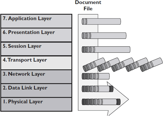
Figure 2-1 The OSI model.
• Layer 7, the Application Layer The Application Layer defines how a user accesses and interacts with data on the network. Application Layer protocols present network data to user application software, such as a media player or a word processor, and vice versa. The Application Layer gives applications access to network services such as email, FTP file transfers, and databases. For example, when a computer user’s web browser requests information from another computer over the Internet, it uses the Application Layer protocol Hypertext Transfer Protocol (HTTP).
• Layer 6, the Presentation Layer Streaming video and a word processor file are very different. The Presentation Layer translates data to an intermediate form that masks the differences between types of data. It also compresses data to reduce the size of the data moving over the network. Presentation Layer protocols may also encrypt and decrypt data for security purposes. For example, say a user needs to send private data over the Internet. The Presentation Layer protocol Transport Layer Security (TLS) is used to encrypt the data and decrypt it at its destination, hiding its contents during transport.
• Layer 5, the Session Layer Session Layer standards and protocols manage dialogues between devices. This layer allows two applications on different devices to “talk.” It establishes the session, manages it, and ends it. This layer establishes dialogue control between the two computers in a session, regulating which side transmits, when, and for how long. For example, when a user holds a web conference, the Session Layer protocol Session Description Protocol (SDP) invites other participant devices to the session and negotiates what kind of media each participant can send and receive. It does not, however, deliver any media itself.
• Layer 4, the Transport Layer Transport Layer protocols manage end-to-end message delivery. When sending information, a Transport Layer protocol may divide long packets into smaller segments as necessary. At the receiving end, the Transport Layer builds segments back into the original message. The Transport Layer may also detect errors and send receipt acknowledgments. Ports are a Transport Layer technology (see Chapter 9).
For IP networks, the Transport Layer protocol will be either Transmission Control Protocol (TCP) or User Datagram Protocol (UDP). The two methods differ in speed and reliability. You must be able to identify, and in many cases decide, what kind of transport protocol your AV devices will use to send information over the network. For example, during a web conference, audio and video are sent using the Transport Layer protocol User Datagram Protocol (UDP). UDP continuously sends the media packets to their destination without waiting for a receipt confirmation.
• Layer 3, the Network Layer The Network Layer addresses data packets and routes them to addresses on the network. This layer translates between physical addresses (MAC addresses) and logical addresses (IP addresses, DNS names). The data unit associated with the Network Layer is the packet. For example, a router receives a web conference packet stream addressed to a particular IP address. It identifies the device that corresponds to the IP address and sends the stream along the most logical route.
• Layer 2, the Data Link Layer The Data Link Layer is responsible for transferring data from one device to another, without errors. The Data Link Layer handles switch-to-switch or router-to-router communication. It converts packets into frames, adding the hardware address (MAC) of the source and destination devices. It sends frames to their physical destination. After sending a frame, the Data Link protocol may wait for acknowledgment from the receiving computer. The data unit associated with the Data Link Layer is the frame. For example, web conference packets are transmitted within Ethernet frames as defined in the Data Link standard 802.3 Ethernet frame structure. The frame identifies the source and destination MAC addresses of the data, includes the data payload and its IP header, and checks for corruption of the data in transit.
• Layer 1, the Physical Layer Physical Layer standards and protocols define the physical means of sending data from one device to another, such as how cables are attached to network adapters or how data is transmitted over radio waves. The Physical Layer doesn’t change the data in any way. The transmission medium itself can vary greatly over the course of transferring data. For example, a signal might start on twisted-pair wiring, move onto a wireless network, and then ultimately end up on fiber. The data unit associated with the Physical Layer is the bit. When Ethernet frames are transmitted from a wireless router to a user’s laptop, they use the Physical Layer 802.11 wireless networking standard. The standard defines what frequency bands the signals are transmitted across and the modulation techniques used to send the data over radio waves.
Physical Layer Transmission Media
Layer 1 of the OSI model, the Physical Layer, deals with how data physically travels from one location to another. It’s also the layer that AV professionals are the most expert in.
As with AV signals, network-based data transmissions take the form of electromagnetic energy, which itself can take many forms: voltage, radio frequency(RF), infrared light, visible light, microwaves, and more. Electromagnetic energy is a flexible medium. As a result, data can travel through many different physical media. The three most common physical transmission media are
• Copper, over which data moves as voltage
• Glass, over which data moves as visible light
• Air, over which data moves as radio frequency
Manufacturers and scientists are always experimenting with ways to transport data faster or more cheaply. Copper wires may someday be replaced by aluminum, or glass fibers with plastic. For the time being, though, these three media dominate.
Within each transmission medium are several options. Different copper cables may have different capabilities, limitations, and designs. The same holds true for fiber cables and wireless transmission technologies. As an AV professional, you should know which medium is best for your application and why.
Copper
The most popular transmission medium for local area networks (LANs) is copper. Copper is an excellent conductor, and it’s a lot cheaper than its neighbors on the periodic table—silver and gold. Although some early networks did employ coaxial cables, today copper network cables are almost exclusively twisted pair.
In a twisted-pair cable, one or more pairs of wires are twisted together to form a single cable run. Each wire is isolated from the others by insulation. All the pairs are further protected by an outer jacket. Twisting the wires helps ensure that each wire is subjected to the same outside interference. This means that the resulting noise can be canceled out in the input circuit, providing significant protection from electromagnetic interference at low frequencies. Figure 2-2 shows four twisted pairs in a category 5e cable.
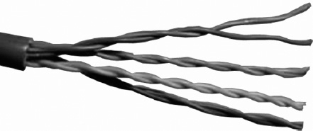
Figure 2-2 Four twisted pairs.
Twisted-pair cables have a defined distance limitation and a certain number of twists per inch depending on the cable type and purpose. The more twists, the higher the manufacturing cost. The closer and more exact the spacing between the conductors, the more balanced the pair is and the greater the noise reduction.
Twisted-pair cable may be either unshielded (UTP) or shielded (STP). Unshielded twisted pair (UTP) is lighter weight, more flexible, and lower in cost than shielded twisted pair. It is commonly used for computer network applications. This cable is ideal for simple system installations, as long as the cable capability is not exceeded. However, as systems demand more bandwidth and greater geographic reach, they’re outgrowing the capabilities of UTP. As a result, STP is increasingly being used in networked applications.
Fiber Optics
Fiber is a glass medium used for transmitting modulated light from point A to point B. The makeup of fiber is pretty simple; at the core is the glass medium used to carry light. The cladding is the next layer of the fiber, which is used to reflect the light back onto the core and keep the signal moving down the fiber. The final layer is the coating, which protects the fiber from damage. An example of a fiber-optic cable is shown in Figure 2-3.
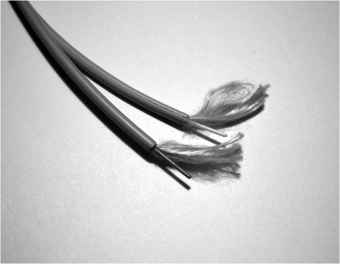
Figure 2-3 A fiber-optic cable.
Fiber-optic cable offers high bandwidth and maintains total electrical isolation. It is able to maintain signal integrity in noisy environments, experiencing little signal degradation over long distances. Fiber-optic cable is also totally immune to electromagnetic and radio frequency interference (EMI and RFI, respectively). It does not burn and withstands aging and corrosion. Fiber-optic lines are also popular for security reasons. It is much more difficult to covertly capture data from a fiber-optic line than by copper wires or radio waves.
There are two modes—or paths of light—that characterize fiber optics: single mode and multimode. Think of single mode as a straight shot; the light path is small in diameter, which makes the signal path mostly straight, with some of the signals bouncing off the walls of the glass. Multimode is a bit different. Some of the signal goes straight down the fiber while the rest of the signal bounces off the cladding. This makes for signal dispersion, which limits the bandwidth. Because the signals are not shooting straight down the cable like they are in single mode, the signals take longer to reach the end of the fiber. This means that transmission over multimode takes longer than transmission over single-mode fiber.
Wireless Transmission
“Wireless” applies to any electromagnetic wave that travels through free space (air). The two main wireless technologies used in networking are Wi-Fi and Bluetooth, although Wi-Fi is predominant.
There are also new wireless technologies coming to market created specifically for AV applications. Although they were designed for consumer electronics, WirelessHD and Wireless Home Digital Interface (WHDI) could also find a place in professional AV installations. Already, companies have introduced WHDI-based presentation and professional camera/monitor products. And, increasingly, AV professionals must pay attention to proprietary wireless technologies, such as Apple’s AirPlay, as clients request their functionality in networked AV systems.
For our purposes, however, Wi-Fi and Bluetooth are the main wireless transmission methods for networked AV systems. Wi-Fi is defined by the IEEE 802.11 standard and has been revised several times to keep up with the growing demands for wireless communication. Bluetooth, which is for low-cost, short-range radio links between devices, has been standardized under IEEE 802.15.1. It transmits and receives in 2.45 GHz frequency band, features built-in encryption and verification, and can carry up to three voice channels, in addition to data.
Both Wi-Fi and Bluetooth allow users to create ad hoc, peer-to-peer networks that are not centrally managed. (Bluetooth is used only for peer-to-peer networking.) Ad hoc networks are great for short-term, low-risk networking. Using a Wi-Fi ad hoc network, a visiting instructor can walk into a classroom and connect her laptop to a wireless projector with minimal effort. Minimal configuration requirements and ease of deployment also make ad hoc networking invaluable during emergencies. In a natural disaster, an ad hoc network can be established quickly for command and control purposes.
However, Wi-Fi is better known for its infrastructure mode, whereby Wi-Fi–enabled devices integrate with a LAN. When you use Wi-Fi in a coffee shop or conference room, you’re in infrastructure mode. The network device that handles a Wi-Fi connection is called an access point (AP) because it controls access to network resources, including WANs, LANs, and the Internet. Figure 2-4 shows a wireless access point.
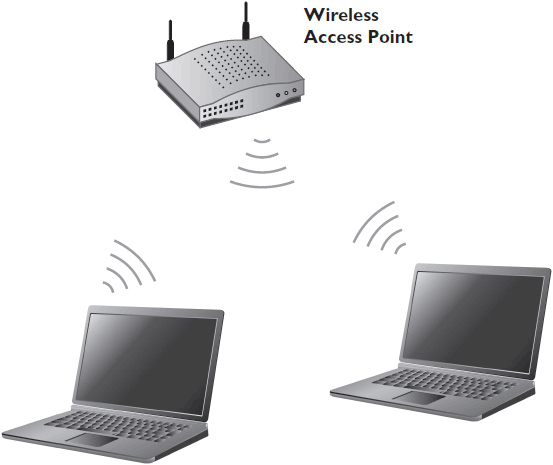
Figure 2-4 A wireless access point.
For devices to establish a wireless connection, the RF signals for transmission must maintain minimum signal strength. To maintain proper signal strength, the devices should be as close together as reasonably possible. Though some wireless systems claim distance limitations of 50 meters (or about 150 feet), the real distance limitations have more to do with the transmitting antenna, the receiving antenna, physical obstructions, and the power output of the transmitters on both ends.
The speed of a Wi-Fi connection depends on the RF signal strength and the version of the 802.11 standard that the networked equipment uses. As signal strength weakens, the speed of the connection slows. The number of users accessing the wireless devices also affects connection speed.
Table 2-1 outlines the most prominent 802.11 wireless standards. Note, though popular once, 802.11b is rarely used today.
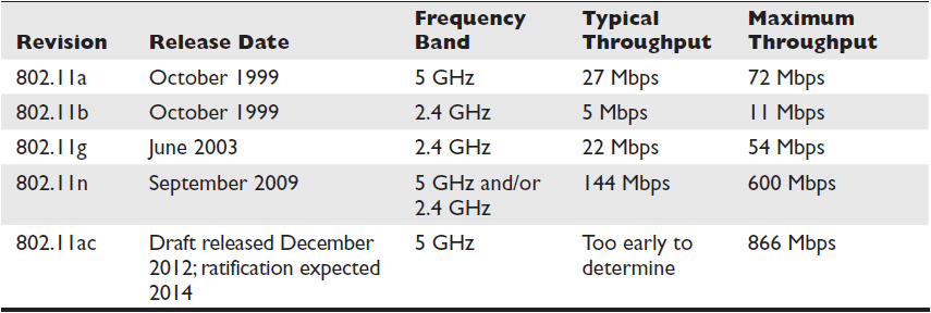
Table 2-1 802.11 Wireless Standards
Common Transmission Media Problems
As you probably know from experience, the signal a transmitter sends out is not always the same as the signal a receiver receives. All data transmission is subject to certain physical realities that can affect the quality of the signal. Fiber, twisted-pair (category or CAT) cabling, and Wi-Fi are all subject to attenuation—signal loss over distance. In addition, fiber is subject to reflective loss; CAT cables are subject to EMI and RFI; and Wi-Fi is subject to RFI.
Properly performed terminations are very important for fiber-optic cabling. If the core is damaged during termination, the cable won’t work. Reflective loss occurs because of a poorly prepared butt splice or end connector, which causes light to reflect back down the fiber instead of reaching the receiving end of the connection.
Electricity on a conductor creates or induces a small magnetic field. The direction of the magnetic field is determined by the direction of the flow of the electricity. This field induces noise onto the adjacent wires or circuits. EMI is caused when a magnetic field comes within range of a wire’s signal and that signal is not strong enough (i.e., high enough voltage) to withstand the disturbance. Magnetic fields are radiated from many sources, including power cables, electric motors, transformers, fluorescent lights, car engines, and dimmers. In analog signals, these magnetic fields induce a voltage heard as a hum or buzz at higher frequencies. In digital signals, the induced voltage can create new “1” bits.
RFI is just EMI at radio frequencies. RFI occurs when noise is induced into a signal through the air. RF signals can induce noise into a circuit or interfere with transmission of other RF signals. In the case of RFI, a wire or Wi-Fi antenna acts as a receiving antenna for the unwanted signal.
EMI in CAT cables is often referred to as cross talk (XT). Cross talk is usually categorized according to where it occurs with respect to testing equipment. When testing a cable, interference measured at the same end as the signal transmitter is called near-end cross talk (NEXT). Interference measured at the opposite end from the signal transmitter is called far-end cross talk (FEXT). Ultimately, it’s all just EMI. Most cross talk can be prevented with proper termination techniques, including minimal untwisting and jacket removal.
Alien cross talk (AXT) is EMI that occurs between two different cables running parallel in close proximity. Alien cross talk is uncommon in UTP cabling that complies with T568A or T568B standards, but it is not unheard of. However, AXT can also occur when low-voltage UTP cables are inadvertently bundled with high-voltage cables, or when UTP cables set in a plenum space (the area above a dropped ceiling used for HVAC air handling without ductwork) are allowed to drape across fluorescent light fixtures.
 TIP If cables carrying signals with different voltages must cross, it is best if they do so at 90 degrees to minimize cross talk.
The Physical Layer and Networked AV Systems
If you’re an experienced AV professional, much of this section will be familiar to you. Networks use many of the same cables and connectors that you use for digital AV signals.
When it comes to networked AV systems, the Physical Layer is likely to be either unshielded twisted-pair (category) or fiber-optic cabling, both of which are discussed in more detail in this section. See Table 2-2 for a rundown of common Physical Layer connections.
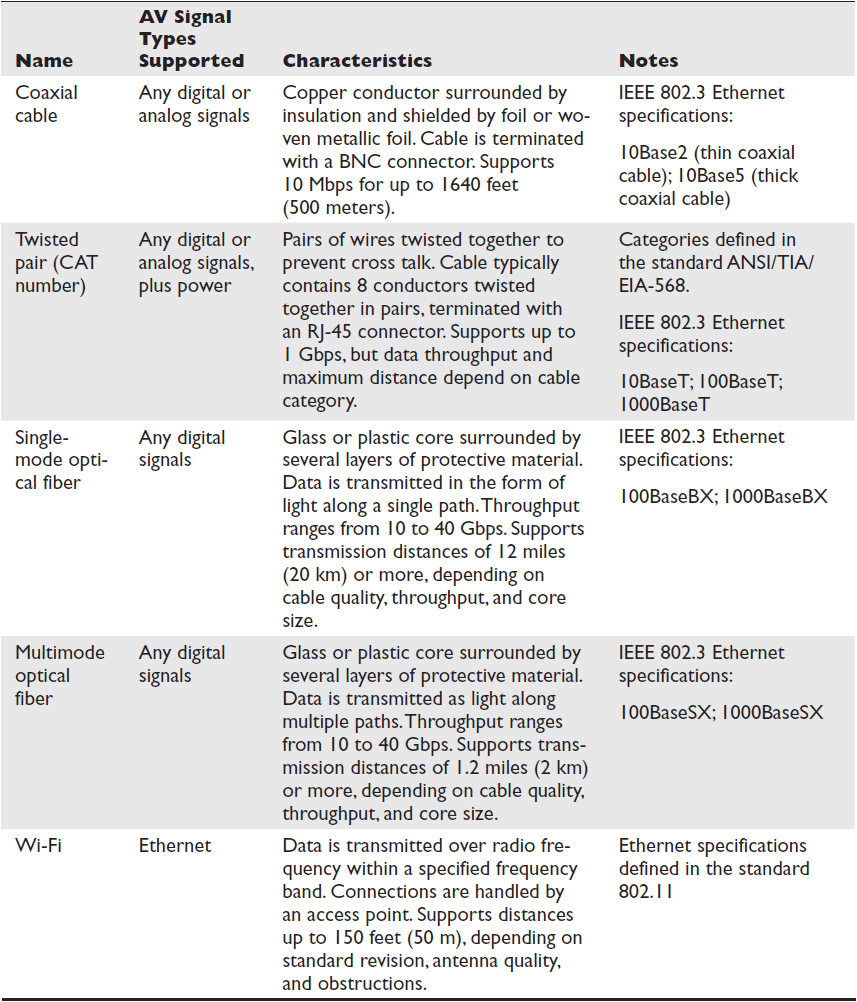
Table 2-2 Common IP Network Physical Layers
At the network edges, where endpoint devices like flat-panel displays or control panels connect, signals may be carried to the user endpoint via nonroutable physical connections, such as the High-Definition Multimedia Interface (HDMI). These interfaces are well known to AV professionals and can carry a combination of audio, video, and data/control signals.
See Table 2-3 for a list of common non-network-specific AV connections and the signals they support. If you require a review, you can find information in the Certified Technology Specialist Exam Guide, Second Edition (McGraw-Hill Education, 2013) or InfoComm International’s online course Essentials of AV Technology Online, which is free to members (infocomm.org/education).
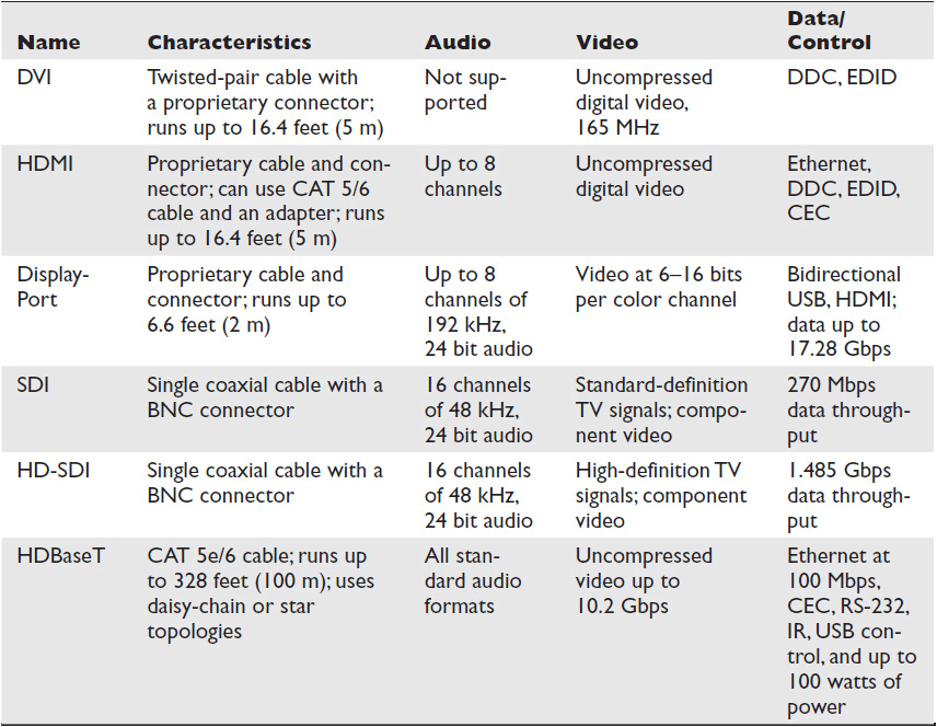
Table 2-3 Common Non-Network Physical Interfaces for Digital AV
Category (CAT) Cabling
As an AV professional, you’re likely to encounter only the twisted- pair cables used in networking, which come in several categories. These categories, often abbreviated CAT, are Ethernet standards under the TIA/EIA-568 standard. In most LANs, you’re likely to encounter only CAT 5, CAT 5e, and CAT 6.
To advertise a cable as CAT cable, all manufacturers must create cable that meets the minimum specified standards for the category. If the manufactured cables are installed and terminated correctly, they should perform as specified. Table 2-4 shows the speeds based on the category cable designation.
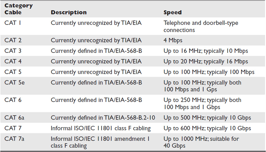
Table 2-4 Rated Performance for Category Cable
Category 5 (CAT 5) is the designation for 100-ohm unshielded twisted-pair cables. It is associated with connecting hardware specified for data transmission up to 100 megabits per second (Mbps). Category 5e (CAT 5e) is an enhanced version of the CAT 5 cable standard. It adds specifications for far-end cross talk.
Category 6 (CAT 6) is a cable standard for Gigabit Ethernet. It is backward compatible with CAT 5, CAT 5e, and CAT 3. CAT 6 features more stringent specifications for cross talk and system noise. The conductors in CAT 6 cables have more twists per inch. They also operate at a high speed (measured in gigabits), which means that they have high frequencies with tiny wavelengths. All of this adds up to CAT 6 cables being susceptible to noise. Therefore, CAT 6 cables should be shielded.
How do you choose between CAT 5e and CAT 6 cables? Both have a maximum distance of 328 feet (100 meters) per cable segment. Both have considerable bandwidth capabilities. CAT 6 is capable of faster speeds, but because of its shielding, it is also heavier, more expensive, and more difficult to field-terminate. See Figure 2-5 for an example of CAT 6 cabling.
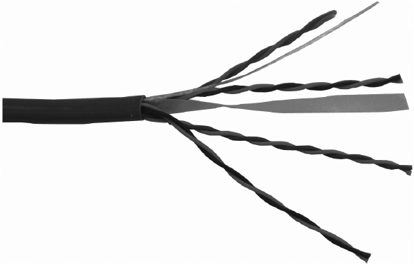
Figure 2-5 CAT 6 cabling.
The choice comes down to what you’re transporting. You may need the higher bandwidth capabilities of CAT 6 for some applications, such as live video or audio streaming. Applications that are less sensitive to dropped packets or latency, such as control systems, can get by just fine using CAT 5e.
 CAUTION If network cables will run through plenum airspace, they must be plenum-rated. In case of a fire, plenum cables must self-extinguish and not reignite. They are coated with materials that produce less smoke and are less toxic than standard PVC cables. In the United States, plenum cabling must comply with international NFPA-262 and American UL-910 standards.
 NOTE Be careful when it comes to riser cabling. Riser cables are used in vertical tray applications (e.g., cable runs between floors, cable risers, or elevator shafts). The spaces these cables run in cannot be used for environmental air. Riser cables must self-extinguish and must prevent the flame from traveling up the cable in a vertical burn test. In the United States, riser cables must comply with UL-1666 standards.
RJ-45 Connectors
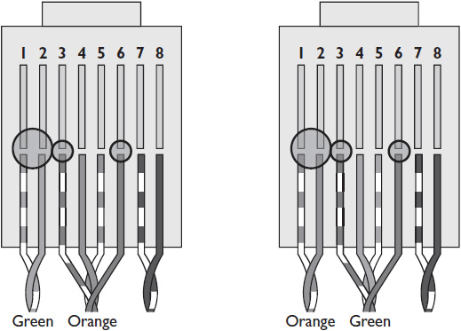
There are two wiring formats within the IEEE 802 standard: T568A and T568B. Both formats are acceptable for use in networked AV systems. An AV installation technician needs to ask the IT manager which format their facility uses. The connector used for CAT cabling is the RJ-45. For Ethernet and Fast Ethernet (100 Mbps) connections, only four of the eight wires in the cables are actually used for data transmission. Gigabit Ethernet uses all eight. The specific pinout depends on the connection standard you are using. The T568A termination standard uses green wires for transmit and orange wires for receive. T568B uses orange for transmit and green for receive. Figures 2-6 and 2-7 show T568A and T568B terminations, respectively.
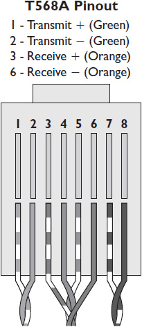
Figure 2-6 A T568A termination.
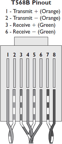
Figure 2-7 A T568B termination
As CAT 6 cables replace CAT 5e in the field, the RJ-45 connectors used to terminate them will begin to look a little different. The shielded CAT 6 cable requires a shielded RJ-45 connector. Shielded connectors have an extra hood on the connector. You must crimp the shield and drain wire onto this hood.
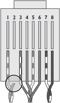
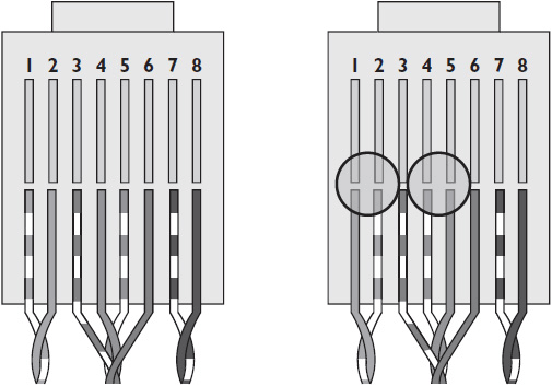
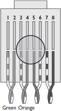
If an RJ-45-terminated CAT cable fails, the likely culprit is improper termination. There are eight wires in a CAT cable. If any one of them is damaged or inserted into the wrong jack hole, the cable can fail. These are some of the most common wiring faults:
• Short circuit Short circuits occur when two bare wires are close enough for electrical energy to arc between them, as shown below. If two wires are punched down into the same jack hole, the cable can short-circuit.
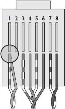
• Open circuit If electrical energy has nowhere to go, the result is an open circuit (shown below). An open circuit can occur in a CAT cable if one or more of the wires is pulled loose or severed instead of being inserted into the proper jack hole.
• Reverse A reverse occurs when a pair is correctly terminated at one end of the cable but incorrectly terminated at the other, as shown below.
• Cross A cross occurs when the orange pair and green pair are crossed (shown below)—essentially, there’s a T568A connection on one end and a T568B connection on the other. The result is a crossover cable, which is useful in some situations as you will learn shortly. It can’t be used as a regular network cable, though.
• Split In RJ-45 connections, pin 1 transmits a positive signal; pin 2 transmits a negative signal; pin 3 receives a positive signal; and pin 6 receives a positive signal. A split occurs when, instead of green being used for transmit and orange for receive—or vice versa—one wire from each of two pairs is used to receive, as shown next.
Crossover Cables
If a cable is terminated with a T568A on one end and a T568B on the other, the cable is known as a crossover cable. See Figure 2-8 for an illustration. A crossover cable allows two devices, such as two computers, to connect and share information without the use of a switch or router that normally does the crossover electronically.
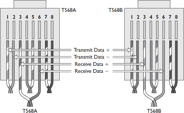
Figure 2-8 Crossover cable with T568A termination on one end and T568B on the other.
In a crossover cable, all pairs have opposite pinning on the near and far ends. Crossover cables are not used as network infrastructure cables in TCP/IP networks. However, they may be used to connect a network device console port to a computer so that configuration changes can be made. As a result, it is common to find a crossover cable in the data closet. Never make assumptions about a cable; always test it before using it.
Fiber-Optic Cabling
One of the most common misconceptions about fiber-optic cabling is that it doesn’t suffer from distance limitations. It does, and the limitations differ depending on which mode you’re using.
Single-mode fiber has one optical path of light that shoots straight down the cable. Multimode, on the other hand, has many paths that light can take, which can limit bandwidth because some of the signal shoots straight down while the rest bounces around until the entire signal reaches the end of the cable.
Typically, single mode can run up to 2,000 meters. The distance limitation of a multimode cable depends on its modal bandwidth, which is the capacity of multimode fiber to carry data over distance. This capacity is normally measured in megahertz over one kilometer (MHz/km).
The ISO, in cooperation with the International Electrotechnical Commission (IEC), published ISO/IEC 11801, and the International Telecommunication Union (ITU) published TAI-492-AAAD to define Optical Multimode (OM) 1 through 4. Table 2-5 shows the OM characteristics associated with current standards. OM transmission standards are given in core diameter (e.g., 62.5) and cladding diameter (e.g., 125).

Table 2-5 Optical Multimode Transmission Standards
When it comes to properly terminating fiber-optic cabling, you have a choice of connectors. All fiber connectors include the same basic components: a ferrule, which holds the fiber in place after termination; a connector body, which holds the ferrule and fiber in place; a cable, which attaches to the connector body to be the point of entry for the fiber; and a coupling device, which mates connectors of the same gender—a common practice in fiber optics.
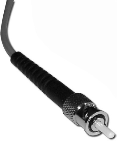
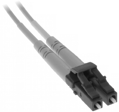
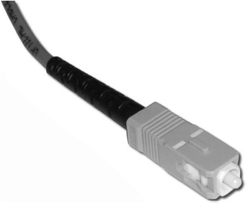
There are a handful of different fiber-optic connectors, described in the following. Currently, the ST, LC, and SC connectors are the most popular for the AV market.
• ST connector The ST connector, shown on the next page, can be found on transmitter-receiver equipment and is very similar to the BNC. It’s a bayonet connector, meaning that all you have to do is “stab and twist” to lock it into place, which keeps the fiber and ferrule from rotating during connection. This connector can be used on both multimode and single-mode fiber.
• LC connector The LC connector, shown below, is much smaller in diameter than the ST and is used for basic wiring applications. It has great low-loss qualities and is known as a “push-pull” connector.
• SC connector The SC connector, shown on the next page, is larger in diameter than the LC. It is a “stab-and-click” connector, which means that when the connector is pushed in or pulled out, there is an audible click. This is a great connector to get in and out of tight spaces.
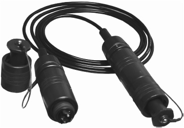
• Hermaphroditic connector While we normally consider connectors to be either male or female, a hermaphroditic connector could be considered both. A hermaphroditic connector, shown below, contains identically paired male and female parts so that it can be mated with another connector sharing the same identically paired male and female parts. These connectors are limited to fiber-optic applications.
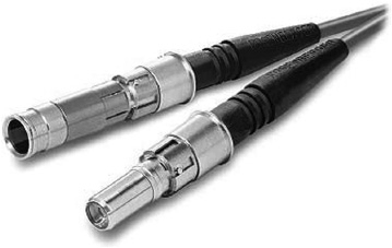
• Expanded-beam connector The expanded-beam connector, shown below, is well suited to use in an outdoor environment because it is more tolerant of dust and dirt and is easier to clean than other connectors.
Long-Distance Communication Media
Wi-Fi and CAT cable are used to transmit data across relatively short distances. Even fiber has distance limitations. So how does the Internet span the entire globe? There are many different long-distance communication technologies at the Physical Layer.
Wi-Fi and CAT cable are designed to carry Ethernet frames (Layer 2) and IP packets (Layer 3). However, in order to travel long distances reliably, data is often translated into a different Layer 2 or Layer 3 technology. It must also typically make a transition from baseband to broadband. These transformations are accomplished by the modem or router that connects the system or LAN to outside networks, resulting in a WAN. The technology used to connect to the Internet or WAN determines the bandwidth available to the end user.
You won’t typically be responsible for choosing your customers’ WAN medium, but it does affect the networked AV systems you install or specify. If your systems send or receive data over the Internet, including remote monitoring and management (see Chapter 13), your clients’ WAN communication medium will affect how quickly that can happen.
Some of the long-distance communication media you are likely to encounter include ISDN, DSL, cable, satellite, T-carrier, and SONET. Let’s take a closer look.
• Integrated Services Digital Network (ISDN) ISDN transmits voice, data, video, and other types of traffic over the digital public switched telephone network (PSTN). ISDN works by logically subdividing the digital signal into two types of channels: bearer channels (B channels) and signaling channels (D channels). B channels carry the data the user is sending. D channels carry call control and other administrative signals. Most data-transmission technologies use one channel for both data and signaling.
ISDN can be divided into two categories: basic and primary. Basic rate ISDN (BRI) is for small businesses and home users. The BRI digital signal is split into two B channels, each supporting 64 Kbps of data. Typically, one B channel is used for voice and the other B channel is used for data. BRI also includes a 16 kbps D channel. The combined rate for BRI is 144 Kbps.
Primary rate ISDN (PRI) is used for larger organizations and for joining multiple BRIs. PRI has twenty-three 64 Kbps B channels and one 64 Kbps D channel. The total capacity of a PRI is 1.54 Mbps.
• Digital subscribers line (DSL) In many places, DSL has replaced ISDN as the preferred solution for small businesses and home users. Like ISDN, DSL uses the twisted-pair PSTN infrastructure to send data. The major difference between DSL and ISDN is the way the modem manages the digital stream. DSL uses 256 discrete multitones to send voice and data over the same line. Tone 1 is used for voice, tones 2–5 are used to buffer between voice and data, and the remaining 250 tones are available for data. By sacrificing four tones, DSL can support simultaneous voice and data on the same wire. There are several varieties of DSL, ranging greatly in speed and capability. Depending on the infrastructure available, a DSL line can offer from 16 kbps to 52 Mbps.
DSL typically offers higher download speeds than upload speeds. This is adequate for users who consume more Internet content than they produce. However, synchronous DSL provides equal upstream and downstream connections.
• Cable Cable Internet access is an alternative to DSL and uses a different preexisting infrastructure. Cable Internet is designed to take advantage of the cable TV network infrastructure to transmit data. Cable networks already support broadband communication, so the transition to data services is relatively simple. Customers are issued a cable modem, which is used to modulate data on a specific frequency that does not interfere with existing television frequencies. Cable Internet access is encrypted from the modem to the cable service provider location. The encryption prevents data disclosure between different users on the cable loop.
• Satellite Modern satellite Internet service is provided via a dedicated set of geostationary satellites. Satellite is available to any user with line-of-sight access to a low-orbit satellite above the equator. However, satellite Internet service is typically more expensive than local, wired Internet access, where available.
Satellite Internet access is affected by weather and dish condensation, making it a less than viable option in areas with excessive rainfall. Initially, satellite communication went one direction only: downstream. Uploading data was accomplished over standard telephone lines. These days, data can be uploaded and downloaded via satellite, although upload speeds are typically slow.
• T-Carrier T-carriers have been around since the late 1950s. Standard T-carrier service for data is still used for WANs to connect high-demand customers to the Internet. A T-carrier line can also provide site-to-site WAN links, without spanning the Internet, for large private networks, or it can act as a secure link to an ISP. In general, the longer the distance required of the T-carrier, the more expensive it is to lease.
T-1 and T-3 lines are the most widely used T-carrier formats. T-carriers work by combining multiple data channels into a single stream. These channels can be individually configured to carry voice or data. The T-carrier line may be purely voice, purely data, or a combination of both. A T-1 is a single twisted-pair wire connected at the customer site to data circuit-terminating equipment (DCE).
A T-1 line offers 24 64-kilobits-per-second (Kbps) channels. The combined data rate for a full T-1 is approximately 1.5 Mbps. A T-3 line combines 28 T-1 circuits for a total of 672 channels, or 44.7 Mbps.
• SONET Synchronous optical network (SONET) is Physical Layer technology that provides high-bandwidth data transfers over fiber optics. SONET is capable of transmitting multiple digital bit streams over single-mode fiber with laser or light-emitting diodes (LEDs). SONET can support transfer speeds up to 40 Gbps.
SONET was originally designed for the transmission of asynchronous transfer mode (ATM) network traffic, but it can now be used for all kinds of traffic: ATM, T-carrier, IP, and so on. SONET is also known as synchronous digital hierarchy (SDH).
Data Link Layers and Networked AV
Now that you understand the important Physical Layer concepts for networked AV systems, let’s turn to the Data Link Layer. The Data Link Layer defines how data is divided and sent to a physical address. The most common Data Link Layer in IP networking is Ethernet.
Ethernet is defined in the IEEE standard 802.3. It can be transported over many Physical layers: coaxial cable, CAT cable, optical fiber, HDMI, and more. Ethernet transports data in frames, including the physical addresses of the sender and destination, control, data, and physical error checking. It supports data throughput speeds of 10 Mbps to 100 Gbps.
The IEEE 802.3 Ethernet standards define a data frame format, network design requirements, and Physical Layer requirements for Ethernet networks. They also define a collision avoidance mechanism for half-duplex Ethernet networks called carrier sense multiple access with collision detection (CSMA/CD). (A half-duplex system provides communication in both directions, but only one direction at a time.) CSMA/CD is really only relevant to networks with multiple-device collision domains—that is, networks that use hubs. Since most enterprise networks now rely solely on switches, CSMA/CD is no longer a critical facet of Ethernet. In fact, the latest Ethernet standards—10 Gbps Ethernet and faster—don’t allow the use of hubs.
Ethernet is the main Data Link Layer technology used to transport information on LANs. Ethernet relies on MAC addresses to identify sources and destinations on a data network. Devices on the same LAN can use Ethernet switches to communicate directly, without having to send their traffic through a router. The switches know the MAC addresses of all connected nodes, so if the destination node is on the same LAN as the sender, the switch can pass the Ethernet frame directly to it. Compared to routing, this is an efficient means of communication, like calling someone on the phone. If your communication has to pass through a router, it’s as if you have to call someone else to get the phone number first. That person may have to call another person and then get back to you, and so on. This is one reason why LANs are so much faster than WANs. It’s also why time-sensitive data, such as live audio and video signals, can often travel through a switch but not a router.
AV Data Link Protocols
Ethernet was not originally designed with real-time communication in mind. Therefore, in order to send AV over Ethernet, other technologies must be used in conjunction with it, either at the Data Link Layer or higher.
Data link protocols such as CobraNet, EtherSound, and Audio Video Bridging (AVB) all use Ethernet frames to package data. Any AV streaming protocol requires a minimum data throughput of 100 Mbps. Many AV link layer protocols require specialized infrastructure (routers, switches, etc.) specifically designed to support them. Choose a link layer according to what signal types you need to transport; whether signals will remain within a LAN or must be openly routable over a WAN; and which signal types the current infrastructure supports. (For more on Ethernet and data link protocols, see Chapter 6.)
There are many reasons developers are working on AV-specific protocols, but the main reason is audio and video streaming. Internet users have grown accustomed to streaming audio and video. In fact, as of 2012, 65 percent of all data downloaded in North America from 9 p.m. to midnight came from audio and video streaming services. That’s an enormous amount of AV being consumed over a network. And it doesn’t require special equipment or network configurations. Just visit YouTube or Netflix on an Internet-connected device and you know how easy it is to stream AV.
But that’s consumer AV. Pro AV does indeed require different solutions.
Why Pro AV Needs Its Own Protocols
Internet services like YouTube and Netflix can offer quality streams of media to multiple users. The AV data has been compressed and encoded before it’s delivered to users—a time-consuming and CPU-intensive process that service providers largely handle behind the scenes.
Even so, users know they have to wait for streaming media. Many videos load for a short time before they play, and the streaming experience is often interrupted by “buffering” while more data downloads. If there isn’t enough bandwidth to deliver the full stream, the service provider may switch to a lower-quality stream or simply pause the stream temporarily.
These inconveniences aren’t permissible in many pro AV applications. Pro AV applications are often live. You’re transporting audio and video that’s being transduced into data in real time. Think about the difference in quality you’ve seen between recorded and live video feeds you see on the Internet. The live feeds are typically much lower resolution, and they often refresh only a few times per second, or even less. That level of quality isn’t acceptable in a pro AV enterprise application. When you’re streaming audio and video in real time, it can’t stop to buffer. If there isn’t enough bandwidth to deliver all the data, the data gets lost or delayed. If the data is lost, the result is unintelligible, clipped audio and blocky video. Some amount of delay, what’s known as latency, may be permissible. It depends on your application. In general, the more interactive the AV application, the less latency it can tolerate. A lecture that’s being streamed live to a spillover room can tolerate several seconds of latency. A live, two-way conversation cannot. A networked audio system in a stadium can’t tolerate much latency either; you don’t want the announcer’s commentary to lag behind the action on the field.
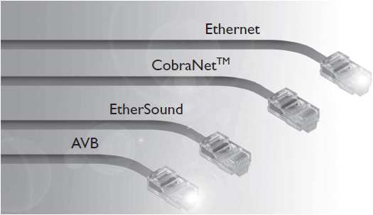
Transporting real-time audio and video to multiple destinations on a LAN typically requires special data link protocols, such as CobraNet, EtherSound, and AVB, designed for that purpose. And there are other AV-specific protocols you will explore in Chapter 6. These protocols make sure that the AV data arrives in sequence, with minimal latency. They also have special network design requirements associated with them: permissible topologies, minimum Ethernet standard requirements, and so on. They may require special hardware or software. They may require AV devices to be isolated in a virtual LAN.
Implementation can be challenging. In the end, though, these special AV protocols allow you to leverage existing IT infrastructures to transport professional-quality AV signals to hundreds of endpoints at once.
Chapter Review
Before you can send any signals across a network, especially AV signals, you have to understand how data travels through that network. In this chapter you learned the seven layers of the OSI model, which define how data moves over a network. One of the most basic and well known to AV professionals is the Physical Layer, which defines the media available for transporting data around an enterprise network. Choosing a transmission medium with the bandwidth and distance range required for your application is crucial to networked AV systems.
You also learned about common transmission problems and what causes them. For example, if you’re responsible for service or field terminations, it’s a good idea to practice proper RJ-45 terminations.
Finally, you got a first glimpse at the Data Link Layer, where Ethernet has come to define the way data is transferred from one device to another on a network. There is much more to learn about Ethernet and Ethernet-related technology in Chapter 6.
Now that you’ve completed this chapter, you should be able to
• Compare and contrast the three most popular network physical transmission media, as well as different category and fiber-optic cable offerings
• Identify the causes of common physical transmission problems
• Describe the most prevalent long-distance communication media
• Understand the basic underpinnings of Ethernet
• Describe the need for and name several networked AV data link protocols
Review Questions
1. What standard best identifies the purpose and use of a wireless connection?
A. SCP X.25
B. IEEE 802.11
C. RFC 761
D. Signaling system 7
2. What happens to the connection speed in a Wi-Fi connection if the signal strength declines?
A. It speeds up.
B. It stops.
C. It remains constant.
D. It slows down.
3. Twisted-pair cables offer protection from electromagnetic interference by _____.
A. shielding each pair inside a foil or braided shield
B. physically separating conductors from higher-voltage signals
C. exposing each wire to the same outside interference, allowing it to be canceled at the input circuit
D. comparing the signal that arrives at the destination device against a checksum
4. The TIA/EIA-568 cable categories you are most likely to encounter on a modern local area network include ______.
A. CAT 1 through CAT 3
B. CAT 5 and lower
C. CAT 5 and higher
D. CAT 8 and higher
5. Crossover cables are used to connect_____.
A. two devices without the use of an electronic crossover device such as a switch or router
B. a device’s network interface card to its MAC address
C. analog devices to digital devices
D. devices configured to accept different Data Link Layer protocols
6. Fiber-optic cable offers longer cable runs than copper because it is _____.
A. immune to electromagnetic and radio frequency interference
B. a better conductor of electricity
C. typically better shielded than CAT cabling
D. less easily damaged
7. Which of the following statements best describes the limitations of Ethernet traffic?
A. Ethernet frames can travel through a router but not a gateway.
B. Ethernet frames can travel through a switch but not a router.
C. Ethernet frames can travel through a hub but not a switch.
D. Ethernet frames can travel through a gateway but not over the open Internet.
8. The IEEE 802.3 standard defines _____. Select all that apply.
A. the connector pinout for Ethernet cables
B. a collision avoidance mechanism for half-duplex networks
C. Physical Layer requirements for Ethernet traffic
D. the data format for Ethernet frames
Answers
1. B. The IEEE 802.11 standard identifies the purpose and use of a wireless connection.
2. D. A Wi-Fi connection slows down if the signal strength declines.
3. C. Twisted-pair cables offer protection from electromagnetic interference by exposing each wire to the same outside interference, allowing it to be canceled at the input circuit.
4. C. The TIA/EIA-568 cable categories you are most likely to encounter on a modern local area network include CAT 5 and higher.
5. A. Crossover cables are used to connect two devices without the use of an electronic crossover device such as a switch or router.
6. A. Fiber-optic cable offers longer cable runs than copper because it is immune to electromagnetic and radio frequency interference.
7. B. The fact that Ethernet frames can travel through a switch but not a router is a limitation of Ethernet traffic.
8. B, C, D. The IEEE 802.3 standard defines a collision avoidance mechanism for half-duplex networks, the Physical Layer requirements for Ethernet traffic, and the data format for Ethernet frames.
