CHAPTER 7
Network Addressing
In this chapter, you will learn about
• Network Layer protocols
• IP addresses
• Types of IP addresses you’re likely to encounter
• How to assign IP addresses to networked devices
• Naming services
Until now, you’ve learned mostly about LAN technologies—those that operate at Layer 2 of the OSI model, the Data Link Layer. Understanding these technologies is foundational for networked AV systems because a lot of networked AV data never leaves the LAN. In fact, as you learned in Chapter 6, it isn’t even possible to route many AV-specific protocols over a wide area network (WAN). Does that mean you don’t need to care about Layers 3 and above? It does not.
Even AV devices that are on their own LAN are connected to a TCP/IP network. You’ll need to assign IP addresses to those devices. The IP addresses are a Network Layer technology. Plus, even if you’re not sending audio or video over a WAN, you may want to send control signals. Layers 3 and higher allow you to monitor and control a networked device from outside the LAN.
What’s more, although networked AV started out primarily on the LAN, it’s fast expanding to the WAN. Routable AV protocols such as Dante and Q-Sys are expanding the range of networked audio; video streaming often takes place primarily over a WAN; and the entire purpose of videoconferencing is long-distance communication. You have to understand the upper layers to understand how tomorrow’s systems will work.
This chapter deals with network addressing—how devices find each other over a WAN. IP addresses allow users and networked AV systems to exchange data securely, without giving away information that might allow unauthorized people to access networked AV devices.
The TCP/IP Stack
A protocol is a set of rules. It defines what a technology will and will not do. Protocols are defined by standards such as the IEEE 802.3 Ethernet standard. Every manufacturer that implements Ethernet protocols in its technology must follow the rules laid out in IEEE 802.3.
On a network, protocols define the rules by which devices communicate. In the early days of networking, there were a wide variety of protocol options at the Network Layer and above. Since the rise of the Internet, though, one suite of protocols has become dominant. It is the set of protocols that ARPANET, and therefore the Internet itself, was based on. It’s practically the only protocol suite that matters at the Network and Transport Layers: the TCP/IP protocol stack.
The OSI model was created to describe any kind of network; its creators didn’t have any specific protocols in mind. The TCP/IP stack is a specific set of protocols, developed by the Internet Engineering Task Force (IETF), divided into four categories (instead of the OSI’s seven): Link, Internet, Transport, and Application. The functions performed by these four categories of protocols can be mapped to the OSI model, as shown in Figure 7-1.
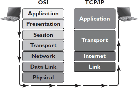
Figure 7-1 The seven layers of the OSI model (left) can be mapped to the four levels of the TCP/IP stack.
The Link Layer of the TCP/IP stack corresponds to the Data Link layer of the OSI model. The Internet Layer of TCP/IP corresponds to the Network Layer of OSI. The protocols categorized as Transport Layer in the TCP/IP stack perform Transport Layer and some Session Layer functions under the OSI model. The TCP/IP Application Layer protocol performs both Presentation and Application Layer functions under OSI. The TCP/IP protocol stack doesn’t address Physical Layer technologies.
Address Resolution Protocol
The purpose of the TCP/IP stack is to take data communication beyond the LAN. Once information leaves the LAN, it’s no longer safe (or practical) to identify it by its MAC address. For one thing, no one wants outsiders to be able to identify an organization’s unique networked devices. Moreover, in order for devices to find each other via MAC addresses, every single device on the Internet would have to register its MAC address in a giant lookup table. Each message would then have to search the enormous table for its destination, slowing things down considerably.
The main role of the TCP/IP Link Layer is to translate between the physical MAC addresses used by Ethernet and the logical IP addresses used on the Internet. This function is performed by the address resolution protocol (ARP).
When a device sends data across an IP network, it knows its own MAC and IP addresses, but it usually knows only the IP address of the destination device. Ethernet can’t read IP addresses; it needs a MAC address to forward data to a destination. When data arrives at a destination LAN, the IP address it used to get there must be translated back into a MAC address. ARP performs this conversion by broadcasting a request containing the destination IP address. The device holding that IP address responds with its MAC address. If no device responds, the data is forwarded to a router to be sent to a new network.
The purpose of the OSI Data Link Layer is to make sure data reaches its next stop. The TCP/IP protocol suite monitors the data’s entire path, making sure it reaches its final destination. The Ethernet header contains the MAC address of the next physical device on the data’s journey. The IP address contains the final destination. When data travels from one destination to another, many separate ARP resolutions are performed on the same packet. When the IP and MAC addresses match, the journey ends.
ARP uses broadcast messaging to resolve addresses, basically asking every device on a LAN, “Is this your IP address?” If that broadcast message had to recur every time a new packet arrived, the LAN connections would get clogged with ARP traffic. In order to avoid this, networking devices such as routers and switches cache the MAC addresses that ARP discovers. In other words, they briefly save MAC addresses resolved through ARP in case they’re needed again. That way, if a stream of packets is addressed to one device—for instance, if a user is streaming video from the Internet to a tablet—ARP has to resolve the address only once for the stream.
Internet Protocol
You’ve heard of Internet Protocol (IP) addresses. You may have even configured an IP address or two. Every device on a TCP/IP network uses at least one IP address. IP covers several crucial functions that make wide area networking possible:
• Addressing Rules for how each system is identified, what the addresses look like, and who is allowed to use which addresses
• Packaging What information must be included with each data packet
• Fragmenting How big each packet can be and how overly large packets will be divided
• Routing What path packets will take from their source to their destination
IP is basically the postal service of the Internet. The postal service sets rules for how to package and address mail. If you don’t include the right information in the address, it won’t be delivered. If you don’t package it correctly, it will get damaged in transit. The postal service also has different levels of service—standard, guaranteed delivery, next-day air, and so on. Similarly, an IP packet contains information about which QoS DiffServ category data belongs to. And just like the postal service, IP assumes responsibility for making sure data arrives at its destination, even though, regrettably, some messages still get lost in the mail.
When you mail a package, it doesn’t travel directly from your doorstep to the address on the label. It first goes to the post office, then to a distribution center, and so on. Similarly, data rarely travels directly from its source to its destination. On a LAN, IP packets are encapsulated within Data Link Layer frames (e.g., Ethernet). The IP address is the final destination of the packet; the frame contains the MAC address of the packet’s next stop. Every intermediate stop the IP packet has to make is called a “hop.”
If the source and destination are on the same network, ARP will be able to resolve the IP address to a MAC address right away. Then the MAC address in the frame header will be the MAC address of the destination device. If the source and destination are on different networks, the packet has to leave the network. Here’s how it works:
• A packet sent by a device receives no resolution to its first ARP broadcast.
• The Ethernet frame header is then addressed to the MAC address of the router that will forward the packet across the WAN.
• When the packet gets to the router, that frame is stripped off and discarded.
• The router generates a new frame, containing the MAC address of the next device the packet will travel to.
• The packet may use and discard several Data Link frames throughout its journey, but the IP packet and address remain unchanged.
IPv4 Packet Format
The Internet Protocol has a lot of responsibilities. The standardized format of IP packets helps networking devices keep track of all the information they need in order to send IP messages. Though IP packets can vary in length, they are all transmitted in 4-byte (32-bit) chunks.
Each byte in an IP package has a specific role. Some bytes contain the data you’re trying to send. Others contain the source or destination address, or they indicate the QoS class. We’ll discuss briefly the function of each field in the IPv4 packet, as depicted in Figure 7-2.
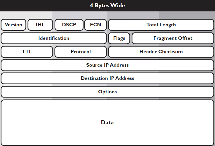
Figure 7-2 IPv4 packet fields.
• Version tells you what version of IP the packet uses.
• Internet header length (IHL) tells you how many 4-byte chunks make up the package’s header. The header must have at least five, but if any IP options are used, it can have more.
• Differentiated services code point (DSCP) tells you which DiffServ class the data belongs to if QoS is implemented.
• Explicit congestion notification (ECN), if implemented throughout the network, notifies network devices of congestion, causing them to lower their transmission rates.
• Total length indicates the total length of the packet, including data. This field is how network devices know when one packet ends and the next begins.
• Identification contains a unique identifier for each packet. If a data message has to be fragmented into several different packets on its journey, this field helps the destination device reassemble them.
• Flags control the data fragmentation process. This field indicates whether the last fragment in a series has been sent. This field can also be set to “Don’t fragment,” which prevents data from being broken up in the first place.
• Fragment offset specifies which fragment the packet is carrying (the first fragment, second, third, etc.), if data is fragmented, so that the data can be reassembled at the destination.
• Time to live (TTL) specifies the number of allowable hops a packet can take on its journey to its destination. This field counts down by one at every hop. If it reaches zero, the packet “times out” and is discarded. TTL prevents orphaned packets from wandering the Internet forever.
• Protocol tells which upper-layer protocol sent the data.
• Header checksum is used to check whether the entire header arrived intact.
• Source address contains the IP address of the device that originally sent the data.
• Destination address contains the IP address of the data’s final destination.
• Options allows optional information to be appended to the packet, such as a time stamp.
• Data, a variable-length field, contains all the actual data you’re trying to send. Typically, this field can be any length, from 1 to more than 65,000 bytes.
IPv6 Packet Format
There are two different versions of IP in use right now: Version 4 and Version 6. The IPv6 packet format is a lot simpler than IPv4, but the addresses themselves are far longer and more complex. Let’s go over the fields included in an IPv6 packet, as shown in Figure 7-3.
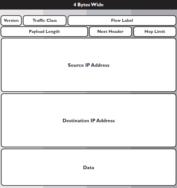
Figure 7-3 IPv6 packet fields.
• Version tells you what version of IP the packet uses.
• Traffic class indicates the data’s class of service, similar to the DSCP field in IPv4.
• Flow label gives “special delivery” instructions. This field indicates if data is part of a sequenced series or belongs to a particular application, such as voice or video.
• Payload length indicates the length, in bytes, of the data payload.
• Next header indicates the upper-layer protocol that sent the data, similar to the Protocol field in IPv4.
• Hop limit indicates the number of allowable hops before data is discarded, similar to the TTL field in IPv4.
• Source address gives the 128-bit IPv6 address of the device that sent the data.
• Destination address gives the 128-bit IPv6 address of the device that is intended to receive the data.
• Data, a variable-length field, contains the data payload and may be up to 65,535 bytes in length.
Fragmenting
One function performed by IP (and something that makes IP decidedly different than the postal service) is fragmenting. If you send a heavy package, the postal service can’t chop it into smaller packages and reassemble it at its destination. IP can.
The original packet of data sent out by a device is called a datagram. Whether that datagram is fragmented during transmission depends on the maximum transmission unit (MTU) of the network connections it encounters. MTU is the size in bytes and includes any header information of the largest frame that can pass over a Data Link Layer connection.
If a packet’s total length is less than the MTU of all the network connections it encounters, it will never be fragmented. The datagram will arrive at its destination unchanged. If the packet is too big for the pipe, however, it will be fragmented before being forwarded to its next hop.
Each fragment becomes its own packet, with its own header. Most of the header information is the same for each fragment, including—crucially—the identification field. The only fields that change are total length (to reflect the length of the newly independent packet), flags (to indicate that there are fragments and whether this packet contains the last one), and fragment offset (to indicate where this fragment belongs in the reassembled datagram).
A datagram could travel through several different network types to reach its destination. Different network connections have different MTUs. For example, an Ethernet network has an MTU of 1,512 bytes and a minimum of 64 bytes. An ATM network has an MTU of 53 bytes. Therefore, in the event a datagram passes from Ethernet to ATM, it will have to be fragmented. A packet may be fragmented many times before it reaches its destination. Moreover, once a datagram is fragmented, it stays fragmented until it is reassembled at its destination, even if it passes through a network segment big enough to render fragmenting unnecessary.
Internet Control Messaging Protocol (ICMP)
In addition to IP, the TCP/IP suite contains another important OSI Network Layer protocol: Internet Control Messaging Protocol (ICMP). It falls under the Internet Layer of TCP/IP. IP defines all the rules for successful data delivery; ICMP notifies devices when data delivery fails.
Network technicians use ICMP to diagnose connectivity issues. ICMP messages are encapsulated in IP packets. Most ICMP transactions occur automatically, generated when an IP packet TTL reaches zero. In such a case, an ICMP “TTL exceeded in transit” message is sent to the source IP address. This lets the sending device know that the packet didn’t arrive. It can then resend the packet or take another corrective action.
Technicians can also send ICMP messages manually. There are two programs that use ICMP to check connectivity—Ping and Traceroute. Ping sends ICMP requests to distant nodes and listens for a reply. Traceroute uses ICMP packets to trace a route across the Internet.
 NOTE With all this talk about IP, ICMP, and the TCP/IP stack, how can there be no mention of TCP? You’ll learn about the Transmission Control Protocol in Chapter 9.
IP Addresses
When data travels across a TCP/IP network, it is identified by the IP address, the protocol identifier, and the port (more on ports in Chapter 9). Together, these three pieces of information make up a socket. In a TCP/IP network, a socket uniquely identifies a session of a given transport protocol. Understanding the first part of the socket—namely, the IP addresses for the device from which data originates and the device to which it’s going—is critical to ensuring proper functionality of networked AV systems. The IP address is defined by the Network/Internet Layer protocol. As noted earlier, it is a logical address that allows devices to locate each other anywhere in the world.
IP addresses can look very different depending on which version of the Internet Protocol—IPv4 or IPv6—was used to create them. The two versions have many differences, but they share some fundamental traits. No matter which version you’re dealing with, an IP address requires three distinct components, which you should be able to recognize and interpret regardless of which version you’re using. These components are as follows:
• Network identifier bits, which help the IP packet find its destination LAN. Network bits are always the first digits in an IP address.
• Host identifier bits, which identify a specific node and help the IP packet find its destination device. Host bits are always the last bits in a network address.
• Netmask, which tells you which bits in the IP address are the network bits and which are the host bits. The netmask also reveals the size of the network. It’s actually a separate address that must be included in the IP address.
In order to understand IP addresses, you need to be familiar with the three main numbering systems used in modern networks: decimal, binary, and hexadecimal.
Decimal Numbering
Remember, the only numbers that a computer understands are 1 and 0. That said, you rarely see network addresses written using only 1s or 0s.
The decimal system is the numbering system you’re probably most familiar with. It’s a base-10 system, meaning it uses ten characters to form numeric values: 0, 1, 2, 3, 4, 5, 6, 7, 8, and 9. It also uses dot-decimal notation, which is any string of decimal numbers separated by a “dot” or decimal mark. In math, you use dot-decimal notation to express fractions of an integer. For example, in dot-decimal notation, 7/4 is expressed as 1.75.
IPv4 addresses are written in what’s called quad-dotted notation—four decimal numbers, each separated by a dot. For example: 192.167.0.8.
 NOTE Most networking professionals refer to quad-dotted notation simply as dot-decimal.
For IP addresses written in dot-decimal/quad-dotted notation, each value will be between 0 and 255. That’s because each decimal number in a quad-dotted address actually represents 8 bits (or 1 byte) of binary digits. Using only 8 bits, you can’t count higher than 255 in binary.
Binary Numbering
Binary is the language computers actually speak. Everything is translated into binary prior to transmission across the network. Binary is a base-2 system, meaning it uses only two characters: 0 and 1. Read aloud, the decimal number 1,101 is “one thousand, one hundred one.” The binary number 1101 would be read aloud as “one one zero one.”
Considering binary is the language computers actually use, why don’t people just express IP addresses in binary? Simply put, it’s long.
An IPv4 address is made up of 32 bits. Here again is our earlier example of an IP4 address: 192.167.0.8. That same IPv4 address, expressed in binary, would be 11000000 10100111 00000000 00001000. (Didn’t catch that? The calculator program that comes with your computer operating system can easily translate decimal into binary. So can your scientific calculator. Give it a try.)
As you can tell, binary numbers just aren’t human friendly. Decimal notation allows you to decrease the number of characters needed to express an IP address. Figure 7-4 illustrates decimal and binary numbering.

Figure 7-4 Decimal and binary numbering.
Hexadecimal Numbering
Hexadecimal numbering is used to express IPv6 and MAC addresses. It’s a base-16 system that uses the same ten characters as decimal notation, plus six letters—A, B, C, D, E, and F.
Hexadecimal characters are often grouped in pairs or groups of four, separated by a colon or dash. The colon or dash isn’t required; it just makes the hexadecimal number easier to read. The letters in a hexadecimal number are not case sensitive, and sometimes you’ll see hexadecimal numbers preceded by “0x” (long story and not relevant to networked AV systems). For example, the following all represent the same value in hexadecimal:
• FFDB12C8
• 0xffdb12c8
• FF:dB:12:c8
• FF-DB-12-C8
• FFDB:12c8
Decimal numbering already offers perfectly good shorthand for binary numbering. So why, you might ask, use hexadecimal notation? Hexadecimal is even shorter. Each hexadecimal character represents 4 binary bits. An IPv6 address is made up of 128 bits. For example, here is the same IPv6 address in binary, decimal, and hexadecimal:
• Binary: 11111110 11001000 10111010 10011000 01110110 10010100 00001000 00000000 11111101 11101100 10111010 10011000 01110110 10010100 00110010 00000001
• Decimal: 65224.47768.30356.2048.65004.47768.30356.12801
• Hexadecimal: fec8:ba98:7654:0080:fdec:ba98:7654:3201
As you can see, writing an IPv6 address in either binary or decimal notation is impractical. Hexadecimal is simply the shortest, most efficient way to express a lot of data.
Figures 7-5 and 7-6 map decimal to hexadecimal numbering and binary to hexadecimal numbering, respectively.

Figure 7-5 Decimal and hexadecimal numbering.

Figure 7-6 Binary and hexadecimal numbering.
IPv4 Addressing
IPv4 was originally defined in 1980, in the IETF standard RFC 760. These days IPv4 is slowly (very slowly) being phased out in favor of IPv6. That said, it’s still the most prevalent IP addressing scheme, so you need to be familiar with its structure. As noted earlier, an IPv4 address is composed of 4 bytes, usually expressed in dot-decimal notation, such as 192.168.1.25. Remember, each of those decimal numbers actually represents 8 bits, so that same address in binary looks like this: 11000000 10101000 00000001 00011001.
The entire range of IPv4 addresses includes every possible combination of 0 and 1 bits. In dot-decimal notation, the range is expressed as 0.0.0.0 to 255.255.255.255. In total, that amounts to almost 4.3 billion possible IPv4 addresses. Several are reserved for specific purposes, but that’s still a lot of possible addresses. Unfortunately, however, it’s not enough. Think about it: There are 7 billion people in the world, about 2.4 billion of whom have Internet access. Now consider how many different Internet-connected devices you personally use each day. This is why IPv4 is being phased out—it can’t support addresses for all the devices that connect to the Internet.
IPv4 Netmask
Looking at an IPv4 address, how can you tell which bits identify the network and which bits identify the host? In order to interpret any IPv4 address, you need a separate 32-bit number called a netmask, or subnet mask.
A netmask is a binary number whose bits correspond to IP addresses on a network. Bits equal to 1 in a subnet mask indicate that the corresponding bits in the IP address identify the network. Bits equal to 0 in a subnet mask indicate that the corresponding bits in the IP address identify the host. IP addresses with the same network identifier bits, as identified by the subnet mask, are on the same subnet.
In structure, an IPv4 netmask looks a lot like an IPv4 address. It is made up of 4 bytes, expressed in dot-decimal notation. A subnet mask could be written something like this: 225.255.255.0. Figure 7-7 shows an IP address and subnet mask, written in binary.

Figure 7-7 Binary representation of an IP address and subnet.
When you write out the netmask in binary, though, you can see the difference between an IPv4 address and a netmask. A netmask never alternates 1s and 0s. The first part of the netmask will be all 1s. The second part of the netmask will be all 0s. Written in binary, the subnet mask for the IPv4 address above would be 11111111 11111111 11111111 00000000.
Used in combination with an IP address, the netmask identifies which bits in the IP address are the network identifier bits and which are the host bits. All the devices on the same network have the same network identifier bits in their IP addresses. Only the host bits differ.
 NOTE When an IP address has all 0s in its host bits, the address refers not to a single device but to an entire network. This address is known as the “network address” or “broadcast domain.” The network address is not routable, and usually can’t be assigned to any one device.
Network Classes and Classless Interdomain Routing
IPv4 addresses were originally assigned and divided into classes, based mainly on the size of the network they were a part of. There were also address classes reserved for specific purposes. Today the size of a network no longer dictates its class; however, you may still hear people refer to a network’s class as shorthand for its size or purpose. Here are the five IPv4 network classes:
• Class A For very large networks. Apple, General Electric, and the US Department of Defense own class A networks. Each class A network can accommodate more than 16.7 million devices with unique addresses.
• Class B For medium-sized networks. A large college campus might have a class B network, which can accommodate up to 65,536 devices.
• Class C For small networks. Class C networks can accommodate up to 256 devices. Initially, they were issued their IPv4 addresses in pairs.
• Class D Networks used for multicasts.
• Class E Reserved for experimental purposes.
You can identify an IP address’s network class by looking at its first byte. Each class also has a default netmask, which is what controls the size of the network. Class A’s netmask had one byte of 1s, class B’s had two, and class C’s had three, leaving the last byte(s) for host bits. See Table 7-1.

Table 7-1 Network Classes by Address and Netmask
In the original IPv4 addressing scheme, all networks were “classful.” That meant every network was a full-class network. If a company requested a class A address space, the requester would get an entire class A network, with more than 16.7 million host addresses. If the company requested class B, it would get class B and more than 65,000 possible addresses.
This scheme wasn’t scalable. As you can see in Table 7-1, there are only 128 possible class A network addresses. In addition, many organizations needed somewhere between 16.7 million and 65,000 addresses, or between 65,000 addresses and 256 addresses. Eventually, IPv4 abandoned strict address classes (IPv6 doesn’t include classful addressing at all).
In 1993 the IETF standard RFC 1517 defined a new netmask system that allowed more flexibility: classless interdomain routing (CIDR). CIDR allows networks of any size to be divided in the middle of a byte of the IP address. This process of network division is known as subnetting, which you will learn more about in Chapter 8.
 NOTE Classless interdomain routing (CIDR) is a method of IP addressing that allows variable-length subnet masks. As opposed to the classful system, under CIDR a network of any size can be issued on an as-needed basis.
CIDR notation is used to identify the size of and boundaries between networks. In CIDR notation, an IPv4 address is followed by a “/” and then a number. That number identifies how many of the address’s most significant bits are network bits. Basically, it’s a shorthand way of writing out the netmask. For example, an IP address written 192.168.1.25/20 has 20 network identifier bits. The remaining 12 are host identifier bits. See Figure 7-8 for an illustration.
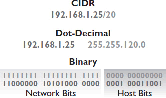
Figure 7-8 CIDR notation.
IPv6 Addressing
IPv6 was defined in 1995 by the IETF standard RFC 1883. Its purpose is to solve IPv4 scalability problems while also improving and easing routing, security, and network administration. As illustrated earlier, IPv6 addresses are much longer than IPv4 addresses, making it possible to include more information and ensuring a virtually unlimited supply of unique IPv6 addresses.
An IPv6 address is composed of 16 bytes (that’s four times as long as an IPv4 address), usually written in eight, four-character hexadecimal “words” separated by colons. Because each hexadecimal character represents 4 bits, each word represents 16 bits. The first three hexadecimal words are the network identifier bits; the next hexadecimal word identifies the subnet; and the final four hexadecimal words are the host identifier bits (see Figure 7-9).

Figure 7-9 An IPv6 address.
Note that the host identifier portion of an IPv6 address is longer than a MAC address. Like an IPv6 address, MAC addresses are expressed in hexadecimal notation. As a result, IPv6 can actually use a device’s MAC address as the host identifier. Some IPv6 implementations even do this automatically. Because a MAC address uniquely identifies a device, using the MAC address as the host identifier should ensure that no two devices ever have the same IPv6 address.
Here is a sample IPv6 address: ca30:0000:0000:00a3:013f:ff4e:070c:000f. That’s pretty long. Fortunately, IPv6 allows you to compress the address by dropping preceding 0s when you write each hexadecimal word. So the address above can be shortened to ca30:0:0:a3:13f:ff4e:70c:f. Notice how the 0s that preceded any part of a hexadecimal word have been dropped.
In addition, some IPv6 addresses have many continuous 0s. You can replace a continuous sequence of all-zero hexadecimal words with a double colon (::). This is called “zero compression.” It only works for hexadecimal words composed entirely of 0s, however, and you can only use zero compression once per address. Here are some examples:
• The address above can be compressed to ca30::a3:13f:ff4e:70c:f.
• The address fd70:0:0:0:0:0:0:0 can be compressed to fd70::.
• The address ffc7:0:0:0:96af:0:0:1 can be compressed to ffc7::96af:0:0:1.
IPv6 Netmasks
IPv6 still uses netmasks, but the netmasks “mask” only a certain part of the address. An IPv6 subnet mask can be written out in eight full hexadecimal words, but the first three words of the netmask will always be 1s and the last four will always be all 0s. As a result, many implementations of IPv6 allow you to enter the subnet mask as a single four-character hexadecimal word. See Figure 7-10.

Figure 7-10 An IPv6 subnet mask.
An IPv6 netmask doesn’t really tell you which bits identify the network and which identify the host. An IPv6 netmask allows you to subdivide the network. You always have 48 more than 281 trillion possible network addresses. Each network address can have more than 18 quintillion unique hosts. As you can tell, we’re not going to run out of IPv6 addresses any time soon.
Even though almost all IPv6 networks are the same size, CIDR notation may still be used to describe an IPv6 network. An IPv6 network that has not been subdivided has a CIDR prefix of /48. If you use all sixteen bits in the subnet group to divide the network, the network will have a CIDR prefix of /64. The IETF recommends using prefixes no smaller than /64, meaning the first 64 bits are the network and subnet identifiers and the remaining 64 bits are the host bits. You may occasionally see an IPv6 address with a CIDR prefix of /128. This is used for loopback connections, that is, connections where the node talks to itself. We explore loopback addresses later in this chapter.
Types of IP Addresses
Under both IPv4 and IPv6, portions of an address range are set aside for specific purposes. As a result, there are several different types of IP addresses that all look pretty much the same. But if you can recognize an IP address’s type, you’ll be able to distinguish which addresses can be used for AV devices and which cannot.
The Internet Assigned Numbers Authority (IANA) is in charge of giving out IP addresses or reserving them for specific purposes. IANA maintains three categories of addresses: reserved, global, and local. Most of the reserved addresses are not routed over the public Internet. Tables 7-2 and 7-3 detail important reserved IP addresses and their purposes.
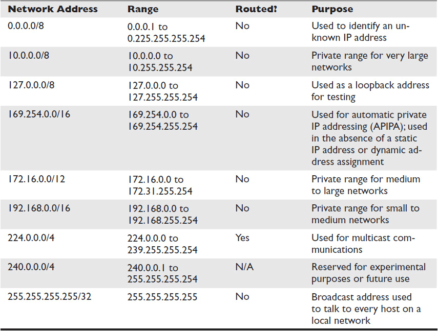
Table 7-2 Reserved IPv4 Addresses
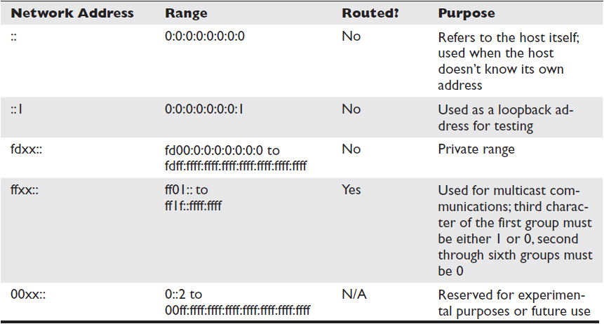
Table 7-3 Reserved IPv6 Addresses
Global IP Addresses
As you know, most LANs connect to the Internet at some point. In order to access the Internet, you need a global IP address. That is, you need a public address that any other Internet-connected device can find.
Global addresses go by many names in the networking community, including globally routable addresses, public addresses, or publicly routed addresses. IANA assigns global addresses upon request. Any IP address that’s not in one of the local or reserved address ranges can be a global address. Basically, global addresses are like an “other” category. If an IP address isn’t a local or reserved address, it’s a global address.
Private Addresses
Not all devices need to access the Internet directly. Many devices only need to communicate with other devices on their LAN. This is particularly true of networked audio implementations.
IANA reserves three IPv4 address ranges and one IPv6 address range for local networking. The addresses in these ranges are private. Devices with private IP addresses can’t access the Internet or communicate directly with devices on other networks. Let’s look at IPv4 and IPv6 private addresses.
IPv4 Private Address Ranges
There are three IPv4 private address ranges. The range you use depends on the size of your network. These ranges were defined before CIDR, so the ranges correspond to the old address classes (see Table 7-4).

Table 7-4 IPv4 Private Addresses
If your network is so big that it would have required a class A address under the old classful system, your IPv4 private address range will start with 10.x.x.x. If your network would have required a class B address, your private address range will start with 172.16-31.x.x. Small networks use private addresses that start with 192.168.x.x.
IPv6 Private Address Range
Under IPv6, all networks are the same size. Therefore, IPv6 only needs one private address range. Private IPv6 addresses are identified by the first two characters of the hexadecimal address. All private IPv6 addresses begin with the hexadecimal characters “fd.” Therefore, the IPv6 private address range is fd00:: to fdff:ffff:ffff:ffff:ffff:ffff:ffff:ffff.
Advantage of Private Addresses
The major advantage of private network addresses is that they are reusable. Global addresses have to be unique—no two organizations can use the same IP address to access the Internet. Otherwise, whenever data was sent to or from that address, there would be no way to know which network was intended.
Because private addresses can’t access the Internet, several different organizations can use the same private address range. Devices on different networks can have the same private IP address because they will never try to talk to each other. As long as no devices on the same LAN have the same IP address, there’s no confusion.
Network Address Translation
The obvious disadvantage of private addresses is that they can only communicate with devices on the same network. They can’t be routed to the Internet. Initially, this made the networking community reluctant to use them. In 1994 the IETF introduced a new service that solved this problem: network address translation (NAT). See Figure 7-11.

Figure 7-11 Network address translation.
NAT is typically implemented in devices at the edges of a LAN—in routers, web servers, or firewalls. When a device with a private IP address sends data out to the public Internet, the data has to stop at one of these edge devices along the way. Before forwarding the packet, the edge device strips the private-source IP address and replaces it with a global IP address. The edge device keeps track of all the data it forwards this way. Then, if any packet receives a reply from the Internet, the edge device can translate the global destination address back into the private IP address that should receive the data.
NAT has several advantages. First, it gives private IP addresses a way to access the Internet, thereby limiting the demand for global addresses. Second, it limits the number of devices exposed to the Internet, enhancing security. Third, if you ever switch Internet service providers (ISPs) and receive a new set of global IP addresses, you only have to configure the addresses of the edge devices. The private addresses don’t have to change.
IPv4 Broadcast Addresses
In addition to private addresses, there are other types of IP addresses that can’t or don’t send data outside the LAN. A broadcast address, when used as a destination address, sends datagrams to every device on the same network (see Figure 7-12).
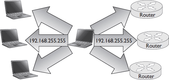
Figure 7-12 Broadcast addresses.
Broadcast addresses are used when one node wants to send an announcement to all network nodes. Broadcast messages are simplex, so there’s no mechanism for the other nodes to reply to the node that sent the message. An IPv4 broadcast address is any IPv4 address with all 1s in the host bits. When data is sent to that address, it goes to every device with the same network bits.
IPv6 Multicast Addresses
Broadcast messages can clog a network, so IPv6 doesn’t employ the broadcast concept. Instead, IPv6 uses multicast, which allows nodes to send messages to specific groups of devices.
Like IPv6 private addresses, IPv6 multicast addresses are identified by a prefix. All IPv6 multicast addresses begin with the characters “ff.” That means that, in binary, the first 8 bits of an IPv6 multicast address are all 1s. In the standard RFC 2373, the IETF defines several multicast addresses that basically replace the functionality of IPv4 broadcast addresses.
An IPv6 multicast address has two critical parts: the scope and the group ID. The scope defines where the data is sent (i.e., to which network), and the group ID defines which devices receive the data. Table 7-5 shows some of the most important multicast scopes defined by the IETF.

Table 7-5 Multicast Scopes
The ability to change the scope of the network you’re contacting with a multicast message is helpful, but IPv6 goes even further. Using the group ID, you can specify what kinds of devices you wish to contact. For example, the multicast group “::1” is defined as “all nodes.” The multicast group “::2” is defined as “all routers.” Therefore:
• The destination address ff02::1 sends a multicast message to all the nodes that are on the same LAN as the sender.
• The destination address ff02::2 sends a multicast message to only the routers that are on the same LAN as the sender (see Figure 7-13).
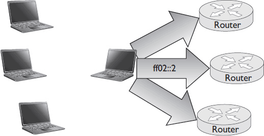
Figure 7-13 IPv6 multicast addressing.
 NOTE In both IPv4 and IPv6, you can define and subscribe nodes to unique, tailor-made multicast groups. These groups are useful in applications such as live video streaming to multiple destinations. The creation of these groups is outside the scope of this book.
Loopback Addresses
Both IPv4 and IPv6 have a special address type for testing devices called the loopback address. Sending data to a loopback address is like calling yourself. Data addressed to a loopback address is returned to the sending device. The loopback address is also known as the “localhost,” or simply “home.”
The loopback address is used for diagnostics and testing. It allows a technician to verify that the device he’s using is receiving local network data. IPv4 and IPv6 each reserve specific addresses for loopback. IPv4 reserves 127.0.0.0 to 127.255.255.255 as loopback addresses. Any address in this range can be used, but most network devices automatically use 127.0.0.1 as their loopback address. IPv6 uses ::1 as a loopback address.
IP Address Assignment
Every device that communicates across a TCP/IP network must have an IP address. Broadly speaking, there are two ways for a device to get an IP address. A device can be manually assigned a permanent address (static addressing), or it can be automatically loaned an address on an as-needed basis (dynamic addressing). Both ways play important roles in introducing AV systems to a network.
Although it requires thoughtful management, dynamic addressing requires less work in general. Instead of manually configuring an IP address for every connected device, nodes obtain addresses on their own. Because all the addressing is handled by computers, dynamic addressing avoids the risk of human error. Users won’t fail to connect because someone typed an incorrect IP address.
Because it’s easier to maintain, especially on larger networks, expect to see dynamic addressing used whenever possible. That said, not all devices support or should use dynamic addressing. Dynamic addresses, by nature, change. Therefore, if, for instance, you need a control system to always be able to locate a device by its IP address, you should assign that device a static address.
Assigning static addresses isn’t hard. Each network operating system has its own tool for doing so. In addition, the individual device may also have a software interface that allows you to hard-code its static address. You need at least three pieces of information in order to manually assign an IP address: the device’s MAC address, the IP address, and the subnet mask.
You might also need to know the address of the default gateway—that is, the address of the router that the device uses to access other networks. If the network uses the domain name system (DNS, covered in the next section), you also need the device’s assigned domain name and DNS server.
Where do you get all this information? Likely from the network manager or IT department. Whenever you add an AV system to a TCP/IP network, you’ll work closely with your IT counterparts to discover and document your system’s requirements. During that process, you’ll let the IT department know which AV devices need IP addresses. The IT department may give you a subnet mask and address range to use, or they may tell you specifically what address to use for each device. In either case, make sure both you and the IT department keep track of which IP addresses and MAC addresses are permanently associated with AV devices.
Dynamic Host Configuration Protocol
When configuring a networked AV system, you must carefully consider how devices will be assigned their IP addresses. A control system, for example, must be able to consistently locate each device it’s managing; therefore static IP addresses may be in order. However, there may be situations when you are limited to whatever addressing scheme a client’s IT department already uses, such as dynamic host configuration protocol (DHCP).
DHCP is an IP addressing scheme that allows network administrators to automate the process of assigning IP addresses. When a device connects to the network and the device has the “obtain IP address automatically” option activated, the DHCP service or server will read the MAC address of the device and assign it an IP address. The pool of available IP addresses is based on the subnet size and the number of addresses that already have been allocated.
A DHCP server will allow a device to hold the IP address for only so long; the amount of time is called the lease time. After the lease time has expired, the lease will usually be renewed automatically if the device is still connected to the network; otherwise another device connecting to the network can use that same address.
The advantage of using DHCP is that it is rather easy to manage. It takes care of making sure no two devices get the same address, relieving potential conflicts, and it allows for more devices to connect to the network, as the pool of addresses is continuously updated and allocated.
The disadvantage of using DHCP is that you never know what a device’s IP address will be from connection to connection. If you need to reach a certain device by IP address, you must have a high level of confidence that the number will be there all the time, and DHCP does not give you that confidence.
A hybrid approach is to reserve a block of addresses for static addresses and dynamic addresses (sometimes called manual or reserve DHCP). In essence, you can use a DHCP server to keep track of manually configured settings, allowing you to maintain all your address assignments—static and dynamic—in a single database. The pool of addresses available for dynamic DHCP addressing is simply reduced by the number of addresses reserved for static devices.
To make this happen, an IT manager will need the MAC address of each device that must be statically set. The static (manually assigned) IP address and MAC address are entered into a table. When the device connects to the network and reveals its MAC address, the DHCP server will see that the IP address is reserved for the device and will enable it. The IP address cannot be given to any other device or MAC address.
DHCP is very powerful, but it takes management, coordination, and meticulous documentation. For example, if the network ever has to be renumbered (maybe the organization changes ISPs), every static address must be manually re-entered. And some AV devices may require special consideration. A multipoint control unit used for conferencing (see Chapter 12) may need multiple IP addresses, for example.
 NOTE If an organization’s IT department uses a DHCP server, it’s best to use a hybrid approach to assigning IP addresses, rather than manually assigning an IP address to each AV device.
Naming Services
Devices on a network must have unique identifiers. At the Data Link Layer, devices are uniquely identified by their MAC addresses. At the Network Layer, devices are uniquely identified by their IP addresses.
What if you want to find the same device over and over? Sending a message to that device’s IP address won’t necessarily work because it may have changed. Even if the device has a static address, you may not always remember it (especially on an IPv6 network).
Naming services allow users and technology managers to identify network resources by a name instead of a number. For example, it’s easier to remember that the boardroom videoconferencing system is named “Boardroom VTC” than to remember its IP address when you need to connect. Plus, even though a device’s IP address may change, its name doesn’t have to.
Computers, of course, don’t understand human language. So how do names translate into IP addresses that computers can understand and use? That depends on the naming system. Your network may use several different naming systems. Each has a slightly different method of resolving names to addresses.
Hosts Files
The oldest naming system is the host system. Under this system, names are associated statically with IP addresses. The name/address associations are stored in a file called a “hosts table” or “hosts file.” The hosts file resides on the LAN. Using the hosts system, a user can send a datagram or request to a host name. In order to resolve that name to an IP address, the system looks up the name in the hosts file. Then it sends the data to the corresponding IP address. Hosts resolve names to addresses without going outside the LAN or sending broadcast traffic. This solution is simple and results in fast address resolution.
Originally, the host system was used to identify all devices on the ARPANET, but because a separate copy of the hosts file had to be maintained on every LAN, the system didn’t last. Whenever a new device connected to the ARPANET, or a device’s IP address changed, all copies of the hosts file had to be updated. Today hosts files are still used, but only for local name/address resolution.
The term “hosts file” actually refers to two different systems—“hosts” and “lmhosts.” Hosts represent an open standard supported by virtually all operating systems. Hosts can resolve names to both IPv4 and IPv6 addresses. Lmhosts are used exclusively by Microsoft to resolve their proprietary name type, called NetBIOS. Lmhosts only support IPv4 address resolution. For that matter, NetBIOS isn’t supported on Windows Vista, Windows Server 2008, and subsequent Microsoft products. Still, you may encounter NetBIOS names and lmhosts on older systems. Because they perform such similar functions, both hosts and lmhosts files are known as “hosts files.” See Figure 7-14 to compare hosts and lmhosts.
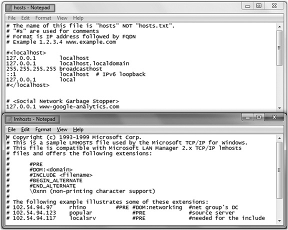
Figure 7-14 Hosts and lmhosts.
DNS
The domain name system (DNS) is the most widely used system for name-to-address resolution. If you use the Internet, you use DNS. The web addresses you type into a browser aren’t actually addresses. They’re DNS names. Every system that connects to the Internet must support DNS resolution.
The goal of the DNS is to translate, or resolve, a name into a specific IP address. DNS relies on “universal resolvability” in order to work: Every name in a DNS must be unique so that information sent to a domain name arrives only at its intended destination.
A DNS server contains a database of names and associated IP addresses. These servers are arranged in a hierarchy. Each server knows the names of the resources beneath it and the name of the server directly above it in the hierarchy. If a server receives a request to resolve a name for a device beneath it, it can resolve that request itself. If it receives a request to resolve the name of an unfamiliar device, it forwards that request to the server above it. This is why the DNS is known as a distributed database. No single device has to keep track of all the names and IP addresses on the Internet. The information is distributed across all the DNS servers on the network.

DNS Hierarchy
DNS names are hierarchical. Every DNS name has at least three levels, known as domains:
• The bottom level—the host domain—identifies the individual device.
• The middle level—the second-level domain—identifies the organization. It is associated with the global IP address of the organization’s primary DNS server.
• The highest level—the top-level domain—identifies the publicly accessible server that houses the name and address of the second-level domain. Common top-level domains include .com, .edu, and .org.
As you may already know, each domain is separated from the next by a period, or dot. So in the DNS name www.infocomm.org, “www” is the host domain, identifying InfoComm’s web server. The second-level domain is “infocomm,” and the top-level domain is “org.” See Figure 7-15 for an illustration of a DNS distributed hierarchy.
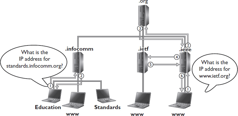
Figure 7-15 How a DNS distributed hierarchy works.
When you access InfoComm’s website, the following steps take place in order to resolve the website’s name into an IP address:
1. The computer looking to connect to www.infocomm.org is first directed to the “.org” server.
2. That server knows the address of InfoComm’s primary DNS server, “.infocomm,” and tells the computer to look there.
3. The computer contacts the “.infocomm” second-level server.
4. InfoComm’s primary DNS server knows the IP addresses of all the devices beneath it, including “www”, the web server. It replies with the IP address the computer was looking for.
It can take several messages between many different DNS servers to resolve a DNS name to an address, something that can generate a lot of traffic. To avoid unnecessarily clogging network pipes, DNS uses a caching system. Devices using DNS record the domain names and IP addresses of recently contacted hosts, such as websites. Each entry in the cache has a limited life span—usually five minutes.
ICANN
All top-level domains in the DNS depend on a single root. The root has no name, which is why it isn’t included at the end of every DNS name. It doesn’t need a name, because it’s always the same.
Root servers house all top-level domains. The Internet’s root servers are managed and operated by an organization known as the Internet Corporation for Assigned Names and Numbers (ICANN), a nonprofit organization chartered to oversee several Internet-related tasks. ICANN manages DNS policy, including the top-level domain space for the Internet.
There are several groups of top-level domains recognized by ICANN. Here are the major ones:
• Generic top-level domains These are usually three characters in length, such as .org, .net, .com, and .gov.
• Country-code top-level domains These are usually two characters in length, such as .us, .co, .cz, and .uk.
• Internationalized country-code top-level domains These are country codes that include non-Latin characters.
• Sponsored top-level domains These are community-themed domains, such as .mobi, .travel, and .info.
ICANN keeps track of these top-level domains using a cluster of computers known as root name servers.
Registering DNS Domains
In order for the DNS to work, all combinations of second- and top-level domains must be unique. For instance, there can be only one infocomm.org, although there could also be an infocomm.com and an infocomm.edu. As long as the second- and top-level domain combination is unique, the host name (www) doesn’t have to be.
When an organization wants to create its own DNS domain, it submits its second- and top-level domains to ICANN for approval through an ICANN-accredited registrar (think GoDaddy). If ICANN approves the combination as unique, then the organization can use it, usually for a fee. ICANN updates the appropriate top-level domain server to include the new second-level domain. Once an organization has a second-level domain, it can name its hosts or subdomains whatever it wants without outside approval.
When creating domain names for devices, there are some limits. DNS names aren’t case sensitive, so you can’t differentiate devices by capitalization. It’s best to use only alphanumeric characters—many special characters, including most punctuation marks, are forbidden. Each domain has a maximum length of 63 characters. The total maximum length of a DNS name is 255 characters.
Subdomains
A DNS name must have at least three levels, but it can have more. Network administrators can create subdomains between the second-level domain and the host domains. For example, a large organization might want a different subdomain for each geographical region it serves, or a different subdomain for each department. For example, in the DNS name www.lasvegas.infocomm.org, “.lasvegas” is a subdomain beneath “.infocomm”. Presumably, this would point to the IP address of a web server that belongs to the Las Vegas branch of InfoComm. See Figure 7-16.
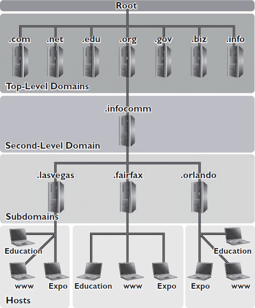
Figure 7-16 An illustration of subdomains.
Zones
Usually, each subdomain has its own DNS server that houses all the names and IP addresses of the devices within that domain. This allows network administrators to break up the task of maintaining the DNS servers. The second-level domain can be broken into separately administered sections, called “zones,” each with its own DNS server(s). Each server is updated with the names and addresses of the devices beneath it. The servers then push that information out to the server(s) directly above them, all the way up to the organization’s primary second-level server.
If a second-level domain has only the domain with hosts directly beneath it, the domain is all one zone. If there are several subdomains, there can be multiple zones. A zone can be any continuous branch of a DNS tree. That means a zone can include several levels of hierarchy, as long as they’re on the same branch. For example, you could create a zone for managing all the AV devices in a geographically dispersed organization. Beneath the second-level DNS server, you could have an “.av” subdomain, with subdomains beneath that for each office location, as shown in Figure 7-17. However, if instead you had a subdomain for each office location beneath the second-level server, with a .av subdomain beneath each of those, you couldn’t manage all the AV devices in a single zone unless the zone included the entire domain.
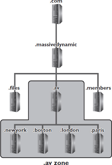
Figure 7-17 An example of a DNS zone.
Fully Qualified Domain Name
The DNS allows devices from all over the world to find each other without an IP address. In order for devices from outside the same domain to find each other, they need a fully qualified domain name (FQDN).
For instance, consider a system used by Bob, who works for Utopia, a commercial establishment. There are many Bobs in the world, but only one Utopia.com. Bob is the only Bob at Utopia. The FQDN for Bob’s system would be bob.utopia.com. If Utopia uses FTP service, the FQDN for Utopia’s FTP server would be ftp.utopia.com.
Relative Domain Names
Within an organization, especially one with several subdomains, you may hear people refer to devices by their relative domain names instead of their FQDNs. Relative domain names are shorthand for referring to systems within the same domain. For example, if you’re working at Utopia, someone may refer to the boardroom control CPU in the New York office as “boardcontrol.nyc.av.” You know that the FQDN your colleague is referring to is “boardcontrol.nyc.av.utopia.com.”
From the user’s perspective, a DNS name performs the same role as an IP address. It’s a way of uniquely identifying a device on a network. Like IP addresses, DNS names provide a means of finding networked devices so you can communicate with them. If AV devices will be part of a network that uses DNS, the devices’ DNS domain names and servers must be documented along with their other addressing information, as illustrated in Table 7-6. The top device has a static IP address; the bottom device gets its IP address dynamically.

Table 7-6 Documenting IP Addressing Information for Networked AV Systems
Chapter Review
In this chapter, you’ve learned ways of identifying devices on a TCP/IP network, including IPv6 addresses, IPv4 addresses, and naming services. Exchanging the right information with your IT counterparts in order to obtain addresses for your AV devices is one of the most fundamental tasks for getting an AV system on the network. Start this conversation early. Examine manufacturer information carefully to determine whether your devices require static addresses. Work with IT to determine which devices need globally routable addresses and which can use private addresses. Make sure devices that need to communicate directly via Ethernet are on the same subnet. Most important, document everything—IP addresses, address allocation methods, network names, and so on. You’ll need that information if something ever goes seriously wrong.
Now that you’ve completed this chapter, you should be able to
• Summarize the functions of the network layer protocols defined in the TCP/IP protocol stack
• Identify the parts and characteristics of IPv4 and IPv6 addresses
• Identify the types of IP addresses, including whether an address is global, local, broadcast, multicast, or loopback for a given IPv4 or IPv6 address
• Identify the number of subnets and hosts for a given IPv4 or IPv6 network
• Distinguish between the most common network naming services
Review Questions
1. The main purpose of address resolution protocol (ARP) is to _______.
A. resolve IPv4 addresses to IPv6 addresses
B. resolve IP addresses to MAC addresses
C. assign IP addresses to Ethernet devices
D. resolve private IP addresses to global IP addresses and vice versa
2. The TCP/IP Internet Layer performs functions at which layer(s) of the OSI model? Select all that apply.
A. Application
B. Presentation
C. Session
D. Transport
E. Network
F. Data Link
G. Physical
3. If a stream of packets is addressed to the same IP address, the corresponding MAC address _______.
A. is discovered once and then cached for the duration of the stream
B. is discovered once and then cached forever
C. is sent to the sending node so the stream can be sent directly over Ethernet
D. must be rediscovered for each packet that arrives
4. Which of the following are layers in the TCP/IP protocol stack? Select all that apply.
A. Application
B. Presentation
C. Session
D. Transport
E. Internet
F. Link
G. Physical
5. Which of the following functions are handled by the Internet Protocol (IP)? Select all that apply.
A. Guaranteeing delivery of packets
B. Logical address structure
C. Resolving logical and physical addresses
D. Fragmenting packets
E. Routing packets
6. Which IPv4 packet header field defines how many hops a packet can take on its way to its destination before it is discarded?
A. Flags
B. Header checksum
C. Total length
D. TTL
7. Data that has been fragmented is reassembled once it reaches ______.
A. a router at the edge of its local area network (LAN)
B. its destination node
C. a network connection with an adequate maximum transmission unit (MTU)
D. the network that contains its destination node
8. Packets are fragmented when _______.
A. they encounter a network connection with a maximum transmission unit (MTU) that is less than the packet size
B. there is not enough available bandwidth to send the entire packet
C. their destination node does not have enough available processing capacity to read the entire packet
D. their source node does not have enough processing capacity to send the entire packet
9. When an IP packet time to live (TTL) reaches zero, a(n) _______message is generated to inform the source device that the data delivery failed.
A. Traceroute
B. IP
C. ICMP
D. TTL
10. Which of the following statements accurately describe hexadecimal numbering? Select all that apply.
A. Hexadecimal numbering is case sensitive.
B. Each hexadecimal character represents 4 binary bits.
C. Hexadecimal numbers are often separated into pairs or quads by a colon or dash.
D. Hexadecimal notation uses the numbers 0 through 9 and the letters A through Z.
11. Bits equal to 1 in a subnet mask indicate that the corresponding bits in an IP address ______.
A. identify the host
B. identify the network
C. are equal to 1
D. are equal to 0
12. In the IP address 192.168.1.0/20, the “/20” indicates that the _______.
A. address has 20 network identifier bits
B. network is divided into 20 subnets
C. network is 1/20 the size of a classful address
D. network can accommodate up to 20 unique host addresses
13. The IPv6 address fc00:0000:0000:009c:0000:0000:0000:2700 can be shortened to _______.
A. fc::9c::27
B. fc00:9c:2700
C. fc00::9c:0:0:0:2700
D. fc00::009c::2700
14. Network address translation (NAT) allows devices with private IP addresses to ______.
A. communicate with devices on other networks
B. communicate with devices on the same network
C. translate IP addresses to MAC addresses
D. join multicast groups
15. When data is addressed to a broadcast address, it is sent to _____.
A. every device on the same switch
B. every router on the network
C. every device with the same network bits
D. every device in the same physical site
16. The IPv6 multicast address _______ performs the same function as an IPv4 broadcast address.
A. ff08::1
B. ff02::2
C. ff01::1
D. ff02::1
17. A loopback address sends data _______.
A. to the network gateway of the sending node
B. back to the node that sent it
C. to the last node that sent data to the sending node
D. to every node in a ring topology, including the sending node
18. What information do you need in order to assign a static address to a device? Select all that apply.
A. IP address
B. Model number
C. Subnet mask
D. Firmware version
E. MAC address
19. An organization needs its own DNS server if it ______.
A. needs to statically associate certain names and IP addresses
B. uses DNS internally to manage the names and addresses of devices on the private network
C. has more than one LAN
D. needs to access the Internet
20. In order for DNS to work, every combination of ______ must be unique.
A. host and top-level domain
B. host and second-level domain
C. second- and top-level domain
D. host, second-level, and top-level domain
21. Reserve DHCP allows you to _______.
A. limit the use of a pool of addresses to a particular VLAN or subnet
B. establish a pool of additional addresses in case the primary pool of addresses runs out
C. assign static IP addresses to devices using a DHCP server
D. set an unlimited lease time for all devices using a DHCP server
Answers
1. B. The main purpose of address resolution protocol (ARP) is to resolve IP addresses to MAC addresses.
2. E. The TCP/IP Internet Layer performs functions at the Network Layer of the OSI model.
3. A. If a stream of packets is addressed to the same IP address, the corresponding MAC address is discovered once and then cached for the duration of the stream.
4. A, D, E, F. The Application, Transport, Internet, and Link layers are part of the TCP/IP stack.
5. B, D, E. IP handles logical address structure, fragmenting packets, and routing packets.
6. D. The TTL IPv4 packet header field defines how many hops a packet can take to its destination before being discarded.
7. B. Data that has been fragmented is reassembled once it reaches its destination node.
8. A. Packets are fragmented when they encounter a network connection with a maximum transmission unit (MTU) that is less than the packet size.
9. C. When an IP packet time to live (TTL) reaches zero, an ICMP message is generated to inform the source device that the data delivery failed.
10. B, C. In hexadecimal numbering, hexadecimal numbers are often separated into pairs or quads by a colon or dash, and each hexadecimal character represents 4 binary bits.
11. B. Bits equal to 1 in a subnet mask indicate that the corresponding bits in an IP address identify the network.
12. A. In the IP address 192.168.1.0/20, the “/20” indicates that the address has 20 network identifier bits.
13. C. The IPv6 address fc00:0000:0000:009c:0000:0000:0000:2700 can be shortened to fc00::9c:0:0:0:2700.
14. A. Network address translation (NAT) allows devices with private IP addresses to communicate with devices on other networks.
15. C. When data is addressed to a broadcast address, it is sent to every device with the same network bits.
16. D. The IPv6 multicast address ff02::1 performs the same function as an IPv4 broadcast address.
17. B. A loopback address sends data back to the node that sent it.
18. A, C, E. You need an IP address, a subnet mask, and a MAC address to assign a static IP address to a networked AV device.
19. B. An organization needs its own DNS server if it uses DNS internally to manage the names and addresses of devices on the private network.
20. C. In order for DNS to work, every combination of second- and top-level domain must be unique.
21. C. Reserve DHCP allows you to assign static IP addresses to devices using a DHCP server.
