CHAPTER 3
![]()
Basic Electronics You Should Know
Some electricians are able to ply their trade without an extensive knowledge of basic electronic theory. After years of experience, usually working with others in the trade, they have become very good with tools, have become rather skilled in related trades such as plumbing and carpentry, have a steady hand and good eye for a neat installation, and so on. With the aid of a hand calculator, they can size out circuit conductors and raceways, and they can page through the National Electrical Code (NEC) to find specs for all kinds of methods and materials.
Many of these workers turn out safe, reliable products, often doing advanced industrial work on a regular basis. But the truth is that they are hampered by a lack of theoretical knowledge. And the same is true for the home crafter-electrician. If you acquire a knowledge of fundamental electronic dynamics and relationships right at the start, you will be on a much better track to building it right the first time, and you will be better able to troubleshoot and diagnose those “tough dog” equipment failures.
An Invisible Domain
What is an electron? It is an elementary particle. Unlike a proton or neutron, as far as we know, it cannot be further subdivided. Protons and neutrons are made up of quarks, but electrons do not appear to be made up of anything smaller or more basic.
Electrons are very small—much smaller than protons and neutrons. Protons and neutrons bind together to form the nucleus of an atom, whereas electrons travel in orbits around this nucleus. The orbits of the planets in our solar system, including Earth, all lie in the same plane, resembling a flat disk. Electrons travel around a nucleus in ever-changing planes that are inclined with respect to each other, so these orbiting electrons are best visualized as inhabiting concentric shells that are discrete distances from the nucleus.
Atoms comprise different elements depending on how many electrons there are in orbit around the nucleus. If there is only one electron, the element is hydrogen. If there are two electrons, it is helium.
The Meaning of Valence
The elements are arranged by atomic number (number of electrons, usually equal to the number of protons or the number of neutrons) in the periodic chart of the elements, and this chart tells us a lot about their properties.
The outer shell is different from the other shells. It may contain anywhere between one and eight electrons, whatever number is necessary in addition to the other shells to make up the total atomic number. The outer shell is called the valence shell, and it is responsible for many of the properties of an element. This is so because the electrons in the valence shell are less tightly bound to the nucleus in comparison with the electrons in the other more inner shells.
Remember that all atoms are in constant motion unless the temperature is absolute zero degrees on the Kelvin scale (0 K), in which case there is no motion of the atoms with respect to one another. If there is any heat, the atoms are in constant motion, often colliding billiard-ball-style with one another and, if it is a gas or liquid, with the inside walls of their container.
When two atoms of the same or different elements approach close enough to each other, they interact in various ways depending on the number of electrons in their valence shells. A large number of combinations and interactions is possible under different pressures and at different temperatures, and this makes up the vast field of chemistry. In the study of electronics, we are concerned primarily with the interactions that make for the behavior of a few semiconductors, such as silicon and germanium, and the activities of electrons when they become free of their valence shells, roaming the vast spaces between atoms and flowing in complex and yet orderly ways within conductors.
For the home crafter-electrician, it is not necessary to travel too far afield, yet it is worthwhile to have some understanding of these wonderful patterns of matter and energy in our universe. In the discussion on basic electronics that follows, we’ll try to strike a balance.
First, a few definitions:
• An ampere (amp) is the measure of the amount of electric current that is flowing through a circuit at any given moment. Specifically, it is the amount of current flowing through a conductor when 6.25 × 10¹⁸ (this is scientific notation for 6.25 followed by 18 zeroes!) electrons pass any given point per second. The water analogy is often useful in understanding electrical circuits: current in amps is similar to gallons per minute of water flowing through a pipe.
• A volt is a measure of the electrical pressure on the flow of electrons. Although amperage is an absolute measure based on a certain number of electrons and a unit of time, voltage is a derivative concept. The definition of a volt depends on the definition of an amp. One volt is defined as the amount of electrical pressure required to force a current of one amp through a resistance of one ohm. Voltage resembles water pressure in a pipe as measured in pounds per square inch.
• It follows that an ohm can be defined as the amount of resistance (opposition to the flow of current) there is in a load when one amp of current flows through it at one volt of electrical pressure. The unit of resistance is also derived from amperage, which itself is not derived but absolute.
Reactance and Impedance
Capacitive reactance is a measure of opposition to the flow of current in a circuit that has capacitance, and it varies with the frequency of the voltage and current in the circuit and the capacitance of the load. Inductive reactance is a measure of opposition to the flow of current in a circuit that has inductance, and it varies with the frequency of the voltage and current in the circuit and the inductance of the load.
Capacitive reactance and inductive reactance are both measured in ohms. They conform to Ohm’s law and behave like resistance in a circuit, although their properties are more complex. The values of these two types of reactance are frequency dependent, unlike resistance, which for the most part remains unchanged regardless of frequency.
Impedance, a very useful concept, is also measured in ohms. It is made up of resistance, capacitive reactance, and inductive reactance, although these are not simply added in a linear fashion. Capacitive and inductive reactance, insofar as they comprise impedance, cancel out each other, and the result combines with resistance to make up impedance.
The precise details for calculating capacitive and inductive reactance are not essential to the home crafter-electrician. The electronic technician, however, uses these operations on a daily basis.
We will need to become familiar with Ohm’s law and its derivative equations, however, and this is discussed later. Before we get into that, let’s look at one more definition: a watt is a measure of electrical power that is produced by a source such as a battery or generator or consumed by a load. One watt (also a derivative concept) is the amount of electrical power manifest by one amp of current that is driven by an electrical pressure of one volt.
Strictly speaking, electrical power as measured in watts [frequently kilowatts (kW), thousands of watts] does not flow in a circuit like amps. Instead, it is transferred from one location in a circuit to another—from the source to the load. The load, if it is a motor, converts most of the electrical power into circular motion. Because a motor is not 100 percent efficient, a fraction of the power is lost, dissipated into the surrounding space in the form of heat. Power never goes away—it just takes different forms. This is a useful concept in troubleshooting electrical circuits and equipment. Always look for the power flow. Power is best depicted by means of a one-line block diagram, with arrowheads to indicate direction.
Current flows through a circuit. Unless there are parallel divergent paths, the amount of current in the circuit is everywhere the same, including inside the source and inside the load. This is a consequence of Kirchoff’s current law, and it is a very useful troubleshooting concept. Current is measured with an ammeter, and to take this measurement, you have to break open a conductor and insert the ammeter in series with the source and load. For this reason, an ordinary multimeter can measure only current that is in the milliamp range. The entire amount of current has to pass through the instrument. Any greater amount would quickly burn up the meter, including the probes.
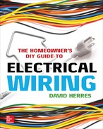
Current can be measured without cutting open the circuit. Using a clamp-on ammeter (Amprobe), as shown in Figure 3-1, you can read up to 200 amps because you are measuring the current indirectly, reading the strength of the magnetic field that surrounds the conductor.
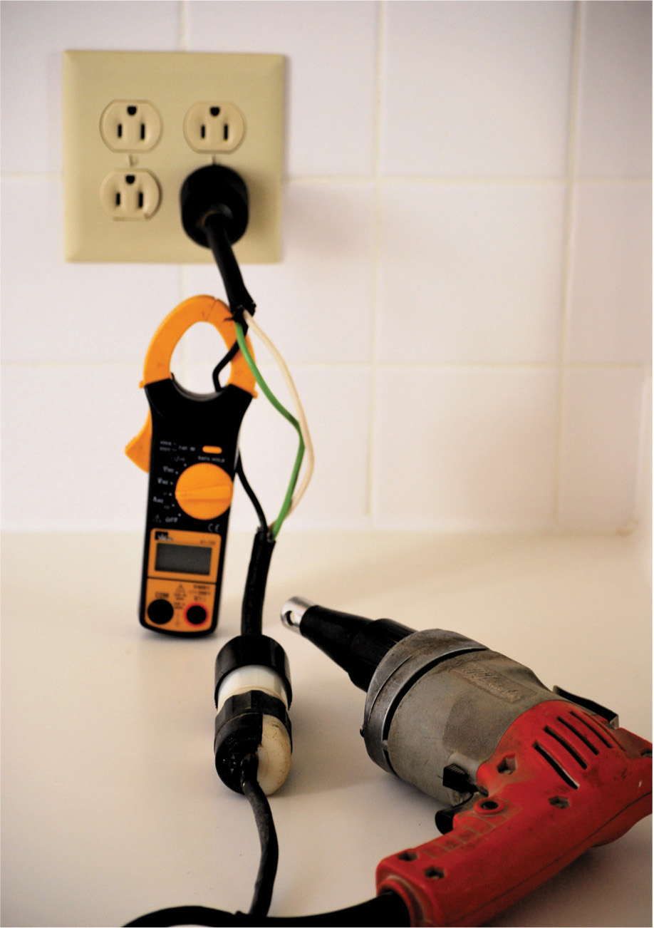
FIGURE 3-1 A clamp-on ammeter reads the current drawn by a portable power tool.
Voltage does not flow through a circuit. It is a potential difference between two points in a circuit. For there to be a reading above 0 volts, there must be an impedance between the two points. In a live circuit, you can test a switch by placing voltmeter probes on the two terminals. If the switch is on, there will be no voltage. Switch it off, and full-circuit voltage is displayed. With the circuit powered down, you can test the switch using an ohmmeter. Place the two probes on the terminals. When the switch is off, you should read very high ohms depending on the range setting of the meter. With the switch on, you should read 0 ohms. Wiggle the handle sideways, and if the reading fluctuates, the switch is bad. If there may be parallel resistance, preventing a true reading, you have to remove the switch from the circuit. Disconnecting just one wire will do it. The voltmeter test is the more professional way to test a switch. Many devices, such as fuses, relays, transistor output circuits, thermostats, and so on, are actually switches, and may be tested as described.
Only a minute amount of current is drawn by a voltmeter. It is safe to read 240 volts using a standard electrician’s voltmeter, provided that it is set to the correct range. Many multimeters can safely read 600 volts. Above that, testing becomes tricky because other issues arise, such as whether the probes can be handled safely.
The home crafter-electrician does not need to read more than 240 volts. Fluorescent bulbs operate at higher voltages, required for ionization, but these are not usually measured. When a fluorescent fixture fails to light, you normally replace first the bulb(s) and then the ballast, as shown in Figure 3-2, and that’s all there is to it.
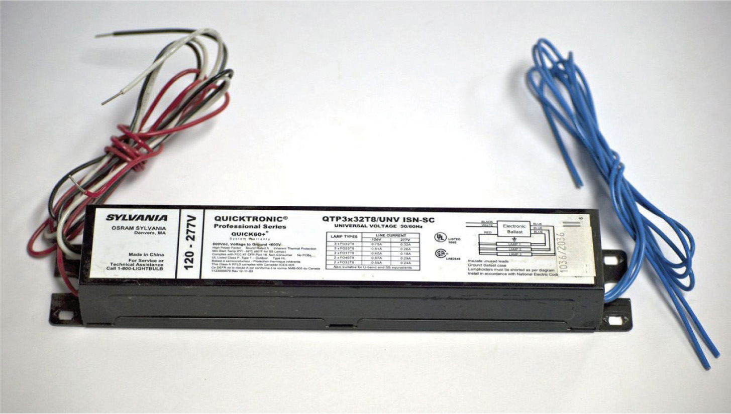
FIGURE 3-2 A fluorescent ballast.
We have discussed amps, volts, and ohms. Now you are 50 percent of the way there. You know the meanings of the three basic electrical circuit parameters. Now we’ll talk about the fundamental mathematical relations among these metrics, and when we are done, you will possess the theoretical background information needed to understand, diagnose, and repair ordinary house wiring circuits. The rest of this book will be easy to follow.
Ohm’s Law
Amps, volts, and ohms relate to one another in accordance with this formula:
E = I × R
where E = volts (electromotive force)
I = amps (intensity)
R = ohms (resistance)
This is the most basic formula, and the others derive from it. Actually, you don’t often use this variant because you rarely need to solve for volts. The voltage is usually known because you know the system voltage supplied by the utility. For almost all residential electrical work, it is 120 or 240 volts depending on which of these you are connected to at the entrance panel. Nevertheless, it is best to know this version because it is easy to remember, and the others can be easily derived from it. You will only need to memorize this one formula, and the other two will be readily available.
When there is an equation such as the one just cited, you can perform the same operation on both sides, and the equation will remain valid. You can also switch the two expressions on either side of the equal sign, and this is usually done for ease in reading so that the single unknown is by itself on the left.
By dividing both sides by I, we get
E/I = R
which is the same as
R = E/I
Using this formula, we can find the resistance in ohms when we know the volts and amps in a circuit.
Similarly, by dividing both sides by R, we get
E/R = I
which is the same as
I = E/R
Using this formula, it is easy to find the current in amps when we know the voltage and resistance in ohms in a circuit. This variant is frequently used because it is always necessary, in an electrical circuit, to know the current that will flow through it in order to size out the conductors and any devices such as switches and relays so that they can carry the load safely.
There is one other formula that, while not actually part of Ohm’s law, is closely associated with it and is frequently used by electricians on any size job. That is,
P = E × I
where P = watts (power). Deriving from this formula, we get
E = P/I
which is rarely used, and
I = P/E
This variant is used very frequently, such as when the voltage and power of a load such as a hot water heater are known and it is desired to find the current in order to size out the supply circuit including conductors and overcurrent device.
Ohm’s law and the power equation interact to yield some other equations, and there is a wonderful graphic that brings all this together. It is called Ohm’s law wheel and is shown in Figure 3-3.
FIGURE 3-3 Ohm’s law wheel displays Ohm’s law and the power equation in all forms for instant access.
If you have assimilated the information introduced so far in this chapter, you have all the theoretical knowledge you need to design, install, troubleshoot, diagnose, and repair ordinary house wiring. There are a few other calculations you will run into from time to time, but for the most part, that knowhow will be derived and follow from the preceding.
Of course, we have to stress that this theoretical background, although important in itself, is only a start. There is a lot to learn about the various wiring devices and how they go together; use of test equipment (especially the multimeter); planning, laying out, installing, and repairing concealed wiring in a home; and some of the extras that you may encounter in home wiring, including data, telephone, and other low-voltage work. Above and beyond this, there is home automation, backup power (including transfer switches), and solar and power cogeneration with synchronous inverter hookup.
Getting Started
Even when you draw a circle so as to exclude everything that is not residential, this is still a big subject. But it won’t be too difficult if you go one step at a time. Begin with some simpler jobs, such as wiring receptacles and switches and doing some home runs to the entrance panel. At this stage, it is a good idea to work with a professional. (It may be feasible to pay $15 and get an apprentice card. Then you can learn on the job.) Before you know it, you’ll be wiring the box, building the service, installing light fixtures, and hooking up three-way switches. In this book, we’ll be looking at these and similar projects. We won’t waste time on feckless discussions about whether the ground prong goes on top or bottom, and we’ll try to refrain from presenting too much detail about harmonic distortion, magnetic resonance, and the like. The goal is to stick to residential wiring and cover as much detail as possible in a single book.
Concealed versus Exposed Wiring
Residential wiring is simpler than commercial or industrial work because it is smaller in scope, there are fewer voltage and current levels with less arc-flash hazard to worry about, and the connected electrical equipment is less complex. In one respect, however, residential work can be more difficult because a better finish appearance is usually necessary. Because most home wiring is concealed, there are accessibility issues that do not arise on the factory floor. Once the walls are filled with insulation and the wiring is covered by wall and ceiling finish, it becomes more difficult to do alterations and repairs because the cabling cannot be easily removed and replaced. In a commercial or industrial environment, even if raceways are behind wall and ceiling material, it is a simple task to install a new cable run using the old wire as a pull rope.
The home crafter-electrician must become adept at concealing wire for the sake of appearance, and where alterations or repairs are being made, this becomes high art. The NEC permits the familiar Type NM cable (Romex) to be stapled to the wall finish, but this is acceptable only in a rustic cabin or unfinished garage. In finished offices and stores, the problem is solved by running wiring above suspended ceilings. Panels can be easily popped out to access the cable so that it can be altered and repaired as needed, and new wiring can be added. Suspended ceilings often are not considered acceptable from an aesthetic point of view in residential living rooms and bedrooms, so we are back to the problems inherent in concealed wiring. One solution, for a retrofit, is to use Wiremold. This is a metal raceway that has a nice finish and is suitable for use on finished surfaces. It comes with a complete line of fittings, enclosures, and devices and very good installation instructions. Many sizes, shapes, and colors are available. It is installed like any raceway, and then conductors are pulled through it. However, it adds to the expense of the job, so it is better to conceal the wiring in the first place where possible.
Residential Work
Now we’ll take a tour through a typical residential electrical installation beginning upstream. We won’t say too much right now about the service because Chapter 4 is devoted to that topic. Suffice it to mention that the service consists of that portion of the premises wiring starting at the utility point of connection and ending at the input terminals of the main overcurrent device, which may be in the entrance panel or in a separate main disconnect enclosure, either inside or outside the building.
The utility often requires that the service be built or at least certified by a licensed electrician, but in any case, the home crafter-electrician should be familiar with this part of the electrical structure because it contains the grounding means and constitutes the jumping-off place for the entire premises wiring. The usual procedure for wiring a house is to begin by mounting the enclosures (with knockouts removed) in place. Then, if the house is wood framing, drill the holes in the studs and framing members using the correct size drill bit. Pull the wires through the holes, staple them to the framing at NEC-specified intervals, and insert the cable ends through the connectors, leaving sufficient free wire at both ends. At the wall boxes, the NEC specifies that 6 inches of free conductor beyond the inner rim of the enclosure be left for making connections. Some workers cut the ends shorter in the belief that it will reduce box fill, but this is a mistake because it is more difficult to make good terminations.
Wiring the Box
At the entrance panel, you need enough length of the black conductor to reach the breaker. The white conductor must be long enough to reach its breaker for a 240-volt circuit or the ground bar for a 120-volt circuit. The bare or green equipment-grounding conductor has to be long enough to reach the grounding terminal. In all cases, leave your whips long enough so that they can be pushed back into the corners of the box. Make all bends right angles, as opposed to taking shortcuts through the available space. In this way, the first few circuits won’t overfill the box, making it difficult to add others.
When it comes time to make terminations, if you find that one of your wires is too short, it is acceptable to make a splice using wire nuts inside an entrance panel. It is better, however, to leave enough free conductor in the first place.
In new construction, it is best to put in the service and heat up the entrance panel at the outset. In this way, there is power to work with, and the temporary service can be removed.
The entrance panel can be in the basement or upstairs, conceivably on the second floor. The NEC prohibits the installation of overcurrent devices (hence entrance panels) in bathrooms, clothes closets, and on stairways, but outside of that, it is your choice. We’ll have much more to say about the location of entrance panels in Chapter 4.
It is best to wire the service entrance conductors into the entrance panel before terminating the branch circuits. In this way, the branch-circuit conductors are not blocked, and they can be shifted around later if the need arises.
The usual location for the entrance panel is in the basement. Then the branch circuits and feeders can be run along joists or sills. They remain accessible for troubleshooting purposes or if changes must be made. Cabling can be run anywhere in the basement and stubbed up through the floor. A centrally located chase inside an interior wall can be built to bring cable runs to the second floor.
If holes are drilled in load-bearing framing members, they should be as small as possible to permit easy installation of cable. A ⅝-inch hole is suitable for 12 American Wire Gauge (AWG) Romex. Large holes should be avoided because they weaken the framing members. A hole drilled near the middle of a long span will weaken it more than if the hole is drilled closer to where the span is supported. A long floor joist will tend to sag near the middle. The top edge of the timber is in compression, and the bottom edge is in tension, that is, trying to stretch. The center is neither in compression nor in tension. Therefore, any holes should be drilled near the center so that there is less tendency to weaken the framing member. This has the added advantage of providing more isolation in regard to nail penetration.
If the entrance panel is to be mounted on a concrete wall, the usual procedure is to make a ¾-inch exterior-grade plywood backing panel that should be about 10 inches wider than the box all around so that cables can be stapled in place. All bends should be 90 degrees for a neat appearance, with the turns gentle enough to comply with the minimum bending radius for the type of cable, as specified in NEC Chapter 3. This work should be precise and neat in order to impress family members and visitors and to facilitate any future wire tracing. It is customary to paint the backing board a low-gloss black.
The NEC has some requirements regarding installation of the entrance panel. If it is mounted directly on the concrete wall, it must have standoffs so that there is at least ¼ inch of air space between the box and the wall. Wooden dowels are not to be used in drilled holes in the masonry.
Most entrance panels use circuit breakers, as shown in Figure 3-4, for overcurrent devices. Fuses are permissible, but they are rarely used in this application because in the course of interrupting the circuit when subject to overload or short circuit, the element burns up, and they must be discarded. Breakers can be reset, and moreover, a breaker box is easier to wire and maintain.

FIGURE 3-4 A 15-amp single-pole breaker used in many 120-volt branch circuits throughout a residence.
A single-phase breaker box, as shown in Figure 3-5, consists of a metal enclosure housing two current-carrying metal bus bars that are insulated from each other and from the metal enclosure. They extend down most of the length of the box, leaving space below for wiring to cross over. At the top, the main breaker fastens to the bus bars. The main breaker is a double-pole breaker with large input lugs for the service-entrance conductors. In the usual single-phase residential system, the voltage between these two lugs measures 240 volts, as does the voltage between the two bus bars. Between either of these and the neutral bar, panel enclosure, or anywhere along the grounding system, the voltage measures 120 volts. This is what is known as a three-wire, two-voltage system. It follows from the fact that the two hot legs originate at the endpoints of the secondary winding inside the utility pole– or pad-mounted transformer, whereas the neutral conductor originates from a center tap of this same winding. When you put your hand on a grounded water faucet in the home, you are putting your hand on the center tap of the secondary winding within the utility transformer and on similar metal at the substation and even at the generating plant. Harmful voltages are not felt because of the low-impedance grounding at numerous points throughout the system.

FIGURE 3-5 A 200-amp entrance panel with double-pole main breaker and main bonding jumper.
While you are installing the entrance panel, there are a couple points to always keep in mind:
• In a service entrance panel, the neutral bar must be bonded to the metal enclosure. The connection is to be made by means of the main bonding jumper, which is attached at the time the box is installed. The reason that it is not part of the box as it comes from the factory is that it is not always required. In fact, it is prohibited when the box is used as a load center downstream from the main disconnect. As stated earlier, such bonding would violate the injunction against multiple bonding of the neutral and equipment-grounding conductors. This connection must be made only once, inside the service entrance panel, and never anywhere else. The main bonding jumper usually takes the form of a threaded screw attached to a card included with the entrance panel. The card reads, “Attach this main bonding jumper in the entrance panel when required.” In the neutral bar, there is a threaded hole for the main bonding jumper. When the box is used as a service-entrance panel, screw the main bonding jumper tightly in place so that it cuts through the paint and digs into the metal of the enclosure, making an electrical connection. If you neglect this simple screw, your enclosure will not be bonded, and if a live wire were to chafe anywhere inside, the box would become energized, creating a hazard. Here’s another very important item that is often neglected by novices: any metal water piping in or on the building must be bonded to the grounding system. To do this for a 100-amp service, use 6 AWG copper wire, solid or stranded, bare or with green insulation. For a 200-amp service, 2 AWG copper is required. Insert one end into the oversize hole in the neutral bar. Run it out through the miniature punch-out at the bottom of the enclosure, and connect it to the nearest metal water pipe using a pipe-grounding clamp made for the purpose. Using this same 6 or 2 AWG wire, make a jumper around the water meter, if there is one, so that if the meter is removed, ground continuity will be preserved. Also jump around any nonmetallic housings, such as associated with water filters, and jump around any short runs of plastic piping that may separate metal segments.
• Fill out the directory, usually attached to the inside of the cover that opens to access the breakers. It is a Code violation to neglect the directory. The printing should be neat and legible. If you use ink, it will be difficult to erase when alterations are made in the future, as is usually the case.
Branch circuits and feeders originate in the panel. A branch circuit runs from the final overcurrent device to the load. A feeder runs from one overcurrent device to another, as in a load center. In other words, a feeder has overcurrent devices at both ends. A mistake novices make is that they place unneeded load centers throughout the occupancy, with local branch circuits emanating spider-web-fashion from each one. This is an expensive variant with no upside unless it is needed in an unusually large building to mitigate voltage drop. When a circuit trips out, it makes for more difficulty in finding the overcurrent device.
Branch circuits are individually wired into separate breakers in the entrance panel. Except for the main, the breakers are purchased separately. Square D, which makes high-quality products, and some other makers require unique breakers that are not compatible with other brands. Many makes are compatible with ITE breakers, which means that the breakers fit the mounts and clip into the bus bar correctly. However, the metal alloys may differ so that over a period of time a corrosion could be a problem. Consult the Underwriters Laboratories (UL) listing, the manufacturer, and the electrical distributor to resolve this problem.
Be sure to include an equipment-grounding conductor. Terminate it at the grounding-terminal strip in a load center or the neutral bar in a service-entrance panel. Put the breaker in place, and route the ungrounded conductor(s) to it. Cut the conductor(s) to length, and strip off just enough insulation so that there is bare wire inside the lug but no copper showing outside. Pull the breaker out, connect the conductor(s) with sufficient torque, and then replace the breaker, making sure that it is seated correctly. Each branch circuit should be completed before tying it into the box to avoid working on live wires.
Grounding conductors and grounded conductors are wired to the neutral bar or the grounding bar. More than one grounding conductor may go into a single lug, but the grounded conductors may not be doubled up. This is so because at some time in the future one of the grounded conductors may have to be removed, at which time the circuit sharing the neutral termination would lose ground continuity, destabilizing the voltage with respect to ground.
The exact height of receptacles is not specified by the NEC. A good height is 10 inches from the subfloor to the bottom of the wall box. Throughout any house, the receptacles all should be the same. Switch heights should be such that the switches can be operated with the forearm level. A good height is 46 inches to the bottom of the box. Thermostats, which take a standard wall box, should be eye level, 60 inches to the bottom of the box. You can make gauges to aid in setting wall boxes to the appropriate heights.
Wall boxes should extend beyond the inside of the framing so that they will be flush with the anticipated finish wall material. Some wall boxes have a mark or ridge to aid in positioning them when ½-inch sheetrock is to be used. Be sure that the wall box does not extend too far out, or the wall plate will not seat on the finish wall, leaving an unsightly gap.
There are several mounting styles for wall boxes. Choose one that works for you. A common type mounts using two 16-penny nails. Boxes are available in metal or plastic. Plastic is a little cheaper, and in a big subdivision or in the life of an electrical contracting firm, the savings would be substantial. On a single small project, the cost difference would not be decisive.
Plastic boxes do not require Romex connectors as long as the cable is stapled within 6 inches of the box. Metal boxes dissipate heat better in case of an arc fault, and they do not contribute to the overall fire load. If home automation is contemplated for the project, plastic wall boxes are better because they make for less radiofrequency (RF) shielding where wireless connectivity is to be used. Both plastic and metal boxes are acceptable if they are UL listed.
When you put in a ground-fault circuit interrupter (GFCI) or if there are multiple runs terminated at a single box or a run going out to a switch loop with wire nuts, it may be very difficult to put the device into the box after it is wired. The solution for this problem is to buy and use deep wall boxes. Some big electrical contractors, to save a few cents on every job, use a shallow wall box for the last receptacle on each branch circuit and for switch loops.
In new work, the usual procedure is to bring the cable into the wall box, tighten the connector (not too tight; just snug so that the cable can’t slide), and then form the wire into a coil and put it into the box so that it won’t interfere with the sheet-rocking process. This completes the job of roughing in the wiring. Later, after the walls are taped and painted, it is time to do the finish electrical work. This consists of pulling the cable ends out of the wall box, slitting the jacket back to about ½ inch from the connector, removing the paper strip, stripping the insulation off the ends of the current-carrying conductors, and wiring the devices.
Wiring the Devices
It is possible to strip the insulation from a conductor using a utility knife with a new sharp blade. Whittle off the insulation as you would sharpen a pencil with a knife. Under no circumstances can the copper be nicked. If that happens, when the circuit is heavily loaded, there will be a hot spot in the wire right next to the termination—and that is a fire waiting to happen! If you nick a wire, cut it back, restrip, and if necessary, connect a short jumper.
Rather than using a knife, a wire stripper does a better job. The automotive type works, but it is bulky and difficult to get into tight places. The professional electrician’s stripping tool is perfect for this job. When stripping the end of a conductor, look at the termination and carefully judge how much insulation to remove. This is critical. The idea is to remove enough insulation so that none of it will get caught under the screw, which would compromise the electrical connection. On the other hand, if you remove too much insulation, there will be exposed copper, which could arc to ground or be a shock hazard.
Some devices have a back-wiring option. The stripped end is inserted into a hole in the back of the device, where it is held in place by spring tension. This type of termination does not have as great ampacity as a good screw termination that is torqued properly. There is rarely a good reason for using the back-wiring option.
It goes without saying that receptacles have to be polarized properly. The grounded (white) conductor is connected to the screw that has a silver finish, and the black conductor is connected to the screw that has the brass finish. Devices that have holes for terminations have the word White or the letter W for the grounded conductor terminal. Devices with separate inputs and outputs, such as GFCIs, are marked with the words Line and Load.
When wiring a residential occupancy, whether it is an entire new building, an addition, or an outbuilding such as an attached garage, the object should be to create a Code-compliant product, and one of the important tasks is to have the correct switch and receptacle placement. Code requirements are exacting. For example, in habitable rooms such as living rooms and bedrooms, there is a prescribed maximum spacing between receptacles. But how do you handle doorways, large archways, glass sliders, and the like? You have to know where in the NEC to find these mandates. They are in Chapter 2, Article 210, “Branch Circuits,” not Chapter 4, Article 406, “Receptacles, Cord Connectors, and Attachment Plugs.” These requirements are maximum intervals, so you are free to install additional receptacles.
Nonelectricians sometimes ask what maximum number of receptacles is permitted on a single branch circuit. This is not the way it works. Seven is sometimes mentioned as a rule of thumb, but adding more receptacles does not increase the load, and it is permitted without limit. Additional receptacles provide more locations for cord and plug connections. The primary hazard is not overloading the circuit because the overcurrent device will take care of that. The primary hazard is overuse of extension cords, so, within reason, the more receptacles the merrier.
Another NEC Violation
While we are on the subject, flexible cords are not to be used as a substitute for permanent wiring. Cords should not be stapled along a wall or run through holes in walls, floors, or ceilings. Wherever a cord is plugged into a receptacle, it must be in sight, not in walls, cavities, above suspended ceilings, or anywhere that is concealed from view.
In nonresidential occupancies, such as stores and factories, there is no mandate on receptacle spacing or minimum number. Receptacles are provided for the anticipated need. In a residence, however, there are definite specifications.
In kitchens, there must be two 20-amp small-appliance circuits. They are usually placed along the counter space. Those within 6 feet of the rim of a sink must be GFCI protected. Even though the circuits are rated 20 amps, the receptacles may be 15 amps. This is an exception to the general idea that the overcurrent device is the weakest link in the chain. Permitted receptacle ratings are listed in Table 3-1.
TABLE 3-1 Maximum Receptacle Ratings for Various Size Circuits

Contrary to common belief, a refrigerator does not need a 20-amp circuit, nor is a GFCI required or even desirable. GFCI protection, generally speaking, is incompatible with refrigeration because loss of power, unnoticed, will equate to food spoilage. Moreover, refrigeration equipment has a tendency to experience nuisance tripping because windings in the hermetically sealed motor-compressor, immersed in fluid, will ground out when the insulating coating bonded to the wire begins to deteriorate. This happens because any slight water contamination in the refrigerant reacts to form an acid that etches down to the copper. Old but still functional refrigerators exhibit enough leakage current to ground to trip out the GFCI. Like all non-double-insulated electrical equipment, refrigerators should have an intact equipment ground to prevent metal parts from remaining energized.
Along the countertop, the receptacles are to be spaced so that no point is more than 24 inches from a receptacle. To maintain this maximum distance, it is necessary to place receptacles every 48 inches, with a receptacle no more than 24 inches from each end or from a sink.
In habitable rooms such as living rooms, dining rooms, bedrooms, and the like, there is a similar geometry, except that the maximum distance of any point from a receptacle measured along the floor line is 6 feet, so the normal interval is 12 feet, except where runs end at breaks such as archways and glass sliders, from which the maximum distance is 6 feet. Complete details are given in NEC Article 210, “Branch Circuits,” which should be reviewed, paying close attention to the wording, prior to beginning this phase of the work.
Switches
Switches are a vital part of any electrical installation, and every home has many of them. They should be provided as the NEC mandates, wired correctly and located for maximum convenience for the end user.
Every habitable room should have a ceiling light. It must be controlled by a switch on the inside wall on the knob side, not the hinge side, of the door. Roughing in the wiring, the electrician should find out which way the door will swing. If there are to be other switches at this same location, they should be grouped in a single two- or three-gang wall box. In this type of configuration, the switch nearest the door should control the light fixture for the convenience of the end user entering the darkened room. The other switches, if there are more than one, should be arranged in some kind of logical order. The NEC permits, where for any reason it is desired not to have a ceiling light fixture, that this switch may control instead a dedicated receptacle that will supply power to a lamp.
Switching may be in either of two configurations. One is the in-line switch, and the other is the switch loop. The one you choose depends on the layout of the room with regard to the location of the power source, switch, and load. You need to decide which alternative is more economical of wire, and that one usually will require less installation labor. If the switch is between the power source and the load, the in-line configuration is better. If the load is between the power source and the switch, a switch-loop configuration is used. In both instances, we are talking about locations along the wire run, not necessarily spatial relations.
To wire an in-line switch, bring cable from the source to the switch. This is called live power. Then run cable from the switch to the load. This is called switched power.
A load could be switched by breaking the grounded conductor (neutral, white), but this would be a Code violation and very dangerous. The load would be turned off, but the ungrounded (hot, black) conductor and internal circuitry would be live. This would create a shock hazard for a maintenance worker who would assume that the equipment is powered down. An in-line switch always should be placed in the grounded conductor. And, of course, the equipment ground is never to be switched.
If the load is 240 volts, it is powered by the two hot legs from the single-phase supply. In this instance, it is necessary to break both ungrounded conductors simultaneously, again without affecting the neutral, if there is one. (Some 240-volt loads require neutrals; others do not. Single-phase motors, baseboard heat, and hot water heaters do not require neutrals. Most electric ranges and similar appliances require neutrals because they contain 120-volt circuits such as lights and/or clocks. In no event is the neutral to be switched.)
The other configuration is the switch loop. Here the live power is brought directly to the load, such as a light fixture, from the entrance panel or load center. The grounded connector is not connected to the switch. Instead, it goes to the load. At the switch, the live power ungrounded conductor is connected to the switch. It is customary to connect this wire to the bottom terminal for consistency and to facilitate troubleshooting and repair, but it will work the same either way.
The NEC requires that a neutral be present in every switch enclosure. It is not necessary for a simple switch to operate. In the case of an in-line switch, it is already there, but for a switch loop, an extra neutral must be provided for future use. To comply with this rule, 14-3 AWG Romex is generally used. In this way, there is an extra neutral (white), the hot supply to the switch (black), and a return hot conductor (red) back to the load. This wire is connected to the hot terminal of the load. The spare neutral is tapped from the neutral line within the load enclosure. The purpose of the extra neutral run to a switch that is on a switch loop is so that if sometime in the future it is decided to upgrade to home automation or energy-saving electronics that require power, it is available. The in-line configuration is more economical because you don’t have to bother with the three-wire cable, so it is often the better choice even when the layout of the room would seem to point to a switch loop.
Wiring Three- and Four-Way Switches
If it happens that a room has two entries, say, at opposite ends, special arrangements are needed. If there were two separate standard single-pole, single-throw switches, one at each end, this would not be satisfactory. If the two switches were in series (like a digital AND gate), both would have to be on to light up the room. If the two switches were in parallel (like a digital OR gate), both would have to be off to turn off the light(s). Either way, there would be instances where the user would have to cross the room in darkness to control the room lighting.
The solution to this dilemma is the three-way switch circuit. This ingenious arrangement allows the user to control the load from either of two locations. The addition of four-way switches permits control from any number of additional locations. Other applications for three-way switch pairs include stairways, outbuildings so that lights can be controlled from inside either building, attached garages, outdoor lighting including porch lights so that it can be controlled from the house or an outbuilding, and so on.
Many individuals have problems wiring these switches together with the source and load and having the final product work correctly. They have to call in a professional to straighten out the terminations and/or cable runs. Even some experienced electricians, if they haven’t done three-way switches in awhile, have to learn them all over. The whole thing becomes simple and easy to remember if you keep a few basic principles in mind.
There are two basic situations with subdivisions. One is the in-line configuration, and the other is the switch-loop configuration. The subdivisions involve whether power from the entrance panel or load center is initially furnished to either the first or the second three-way switch or to the load.
Three-way switches are specialized devices. The handle has no marked on or off position because this varies depending on the state of the other three-way switch. It has three terminals, all colored brass because there is never a neutral (white) connected to it. On one end of the body is a single terminal, marked “common.” On the other end of the body are two terminals that are not marked. Electricians call the conductors that are connected to them travelers.
If you have a three-way switch on hand, set your multimeter to the ohms function, and ring it out. You will see that regardless of the position of the handle, there is never continuity between the traveler terminals. Between the common and one of the traveler terminals, there is continuity when the handle is thrown one way and no continuity when the handle is thrown the other way. Between the common and the other terminal, there is continuity only when the handle is thrown the opposite way. In other words, by throwing the switch alternate ways, you can connect the common to either of the two traveler terminals one at a time but never to both simultaneously.
The two three-way switches are mounted in the two locations where switching of the load is desired. From the power source, bring a run of 12-2 AWG Romex into the first three-way switch wall box. Do not connect the ungrounded (white) conductor to the switch. Wire-nut it through to the other three-way switch wall box, where it is similarly wire-nutted through to the load. Electrically, the white is connected only to the power source and to the load, never to a switch. The ungrounded (black) conductor from the power source is connected to the common terminal of the first three-way switch.
Between the two traveler terminals of the first three-way switch and the two traveler terminals of the second three-way switch, a different type of cable is used. By way of background, 14 AWG conductors are permitted for many household loads because the ampacity is sufficient. Other loads require 12 AWG conductors. Many electricians, to simplify inventory and just because they think it is better, use 12 AWG for all lightweight branch circuits, even where 14 AWG would suffice. An exception, however, is for switch loops, where three-wire cable is needed, load permitting. (This cable actually has four wires if you include the equipment ground, but for this nomenclature, it doesn’t count.)
Between the two three-wire switches, run 14-3 AWG Romex. This cable consists of one each of white, black, red, and, as always, a bare or green equipment-grounding conductor. The white is for the grounded neutral, and the red and black are the travelers. (I call them politicians in order to introduce a little humor into an otherwise dry topic.)
Black and red are insulation colors indicating that the conductors are ungrounded or hot. Actually, any color can be used to denote ungrounded conductors except for white, which is reserved for a grounded conductor, and green, which is reserved for a grounding conductor. If you were running raceways including Wiremold, you could pull a green and a white, with yellow and blue, for example, for the travelers, but with Romex, you are limited to what is available, which is white, black, red, green, or bare.
The 14-3 AWG Romex is the only cable between the two three-way switches. At each end of the 14-3 AWG Romex, the black traveler is connected to one traveler terminal, and the red is connected to the other. It does not matter which is which or if they cross over.
From the second three-way switch, that is to say, the one that is farther from the power source and closer to the load, run 12-2 AWG Romex to the load. At this switch, connect the black conductor to the common terminal, and wire-nut the white conductors that just pass through the two three-way switch enclosures with no electrical connection to either switch. At the load end, which is usually a light fixture that has one black and one white lead, wire it up the conventional way, color to color (this is electricians’ jargon that means white to white and black to black).
This covers the most basic circuit for a pair of three-way switches when they are in the in-line configuration; that is, both switches are located (electrically) between the power source and the load. The best way to visualize the pair of three-way switches is as a single black box, the travelers and interiors of the two switches being inside this conceptual box, with the common terminals of the two three-way switches mounted on the outside of the box. This single unit functions as a standard single-pole, single-throw switch. There is either continuity between the two common terminals, in which case the load is powered up, or there is no such power to the load. The two three-way switches should be regarded as positioned so that the traveler terminals are facing (electrically) one another. The common terminal of the first three-way switch faces the power source, and it is the input to the pair of switches, seen as a unit. The common terminal of the second three-way switch faces the load, and it is the output.
If it is desired to have more than two locations that will be capable of controlling the load, additional three-way switches won’t work. The way it is done is to insert one or more four-way switches in the travelers’ line. There is no limit to how many can be used. As the name suggests, a four-way switch has four terminals, a pair that is the input at one end of the switch body and a pair that is the output at the other end. It doesn’t matter which end is which, and you don’t have to keep track of the travelers. They may cross over any number of times between the two three-way switches. Four-way switches are easier to wire than three-way switches. Just remember that the white wires are wire-nutted straight through from power source to load, with no connection to any of the switches. It’s helpful to ring out a four-way switch using your multimeter in the ohms mode.
Three-Way Switch Loop Configuration
Three-way switch loops accomplish the same results with somewhat different circuit wizardry. A switch loop is useful in a situation where it is more economical to run power from the source directly to the load and from there cable down to the three-way switches and any four-way switches along the way. Connect the neutral (white) of the 12-2 AWG from the source directly to the neutral terminal of the load. Do not connect the ungrounded conductor to the load. Instead, wire-nut it through the nearer three-way switch and onto the farther three-way switch, where it connects to the common terminal, becoming the input to the black box.
Here’s the part that causes difficulty: if the whites in the loop are reidentified and used as return hot wires, this leaves us with no conductor to provide the neutral for future use. Therefore, it is necessary to run a 14-3 AWG wire from the load to the first three-way switch and a 14-4 AWG wire between the two three-way switches. The 14-4 AWG wire will have one white conductor and three conductors that are other than white or green. Use two of these colored conductors as travelers, one as the supply for the common that is the input and the white as the extra neutral.
What if you want to bring power from the source to the first three-way switch? Then you won’t need an extra neutral there because you already have it. You will need 14-4 AWG wire to get a spare neutral, two travelers, and a return hot wire to the second three-way switch.
In view of the expense (14-4 AWG wire costs twice as much as 14-3 AWG wire), it is best to avoid switch loops. Note also that the spare coils and wire nuts increase box fill, so be sure to use deep boxes. Most of the time, in-line switching is best even if the runs are a little longer. Dimmer switches are wired using the same circuits. Three- and four-way dimmers are available.
Sizing Feeders and Services
When it comes to sizing residential electrical work, some NEC navigation with table reading and number crunching is needed. We’ll have a lot to say about services in Chapter 4, but for now, we’ll consider the general procedure for sizing them. The point of departure is NEC Table 220.12, “General Lighting Loads by Occupancy,” which is reproduced here:

In the left column appear 18 types of occupancies with load per unit of area. The right column gives inch-pound numbers rather than metric. Notice that there is a substantial difference in the electrical lighting load for different occupancies. At the low end are storage warehouses at ¼ volt-amp per square foot. This is so because most of the time, for most of the building, the lights are off.
At the other end of the scale are banks and office buildings, both of which are rated at 3½ volt-amps per square foot. Dwelling units are not far behind, at three volt-amps per square foot. For dwelling units, the calculated floor area does not include open porches, garages, or unused or unfinished spaces not adaptable for future use.
For dwellings, unlike other occupancies, this general lighting load includes the receptacles, which for nondwellings after derating have to be added in separately. So what remains is to make a list of all appliances and nonreceptacle/lighting loads together with applicable rules and derating factors. This subtotal is added to the general lighting load to find the total connected load. The total is divided by the system voltage to obtain the number of amps, which determines the size of the service for a new building. For an addition, you will be able to determine whether it is necessary to upgrade to a larger service. Many existing buildings have a 100-ampere service that is filled to capacity, so a new service is always a distinct possibility.
Associated with the preceding table are supplementary provisions and explanatory material in Sections A through L, so consult the NEC to make sure that you have everything figured correctly. When setting up the branch circuit sizes, remember that motors and continuous loads are calculated at 125 percent of the nameplate rating, but this surcharge does not have to be added when sizing the service. Such equipment is usually manufactured in sizes with seemingly odd ratings that when multiplied by 1.25 qualify for standard-size overcurrent protection. Continuous loads are those expected to operate for over 3 hours. An example of a continuous load is electric baseboard heat. An example of a noncontinuous load is a quick-recovery electric hot water heater. For circuits supplying inductive and light-emitting diode (LED) lighting loads that have ballasts, transformers, autotransformers, or LED drivers, the calculated load is to be based on the total ampere rating of the units, not the watt ratings of the bulbs.
An important principle to keep in mind in doing these and similar calculations is that where there are noncoincident loads, only the larger of them needs to be figured in. The classic example of noncoincident loads is heating and air conditioning.
In a kitchen, recall that two 20-amp small-appliance circuits are required. They have to be added as part of the total connected load. They are figured as 1,500 volt-amps each. A laundry circuit also must be provided. It is likewise figured at 1,500 volt-amps. Both the two small-appliance kitchen loads and the laundry circuit load may be added to the general lighting load so as to be subject to the demand factor in NEC Table 220.42.
It is permissible to apply a demand factor of 75 percent to the nameplate rating of four or more electrical appliances fastened in place, other than electric ranges, clothes dryers, space-heating equipment, or air-conditioning equipment in a dwelling. Electric clothes dryers in a dwelling are to be either 5,000 watts or the nameplate rating, whichever is larger. There is no permitted demand factor unless there are over four clothes dryers.
The Infamous Column C
Now we come to a more complex set of calculations, all based on Table 220.55 together with footnotes and explanatory wording. Table 220.55 is titled, “Demand Factors and Loads for Household Electric Ranges, Wall-Mounted Ovens, Counter-Mounted Cooking Units, and Other Household Cooking Appliances over l¾-kW Rating.” It is stated that Column C is to be used in all cases except as otherwise permitted in Note 3.
The table is used for most electrical work in residential kitchens unless the cooking equipment is gas fired. The body of the table gives demand factors as percentages for Columns A and B. But for Column C, it is not a percentage demand factor. Instead, it is a maximum demand in kilowatts. That is why the table looks peculiar at first glance. We are used to reading tables populated by data that are in the same units.
Columns A and B are optional. Column A may be used if the appliances are rated at less than 3½ kW. Column B may be used if the appliances are rated as 3½ through 8¾ kW. For Column C, there is no kilowatt rating minimum, and the maximum is much higher than Column B (12 kW), which is higher than you will see in residential work.
So we see that Column C may be used anywhere that Column A or B can be used. It goes higher than either column. It may seem strange that this table covers as many as 61 appliances, but this is necessary for large apartment buildings with many individual kitchens on the same service.
Before the load is totaled for the purpose of calculating the size of the service, there is one other operation that is permitted, and it has the effect of reducing the size of the service that is required. NEC Table 220.42, “Lighting Load Demand Factors,” lists percentages that may be applied for various occupancies. We are interested in the first row, dwellings, shown in Table 3-2.
TABLE 3-2 Lighting Load Demand Factors

Notice that no reduction is permitted for the first 3,000 volt-amperes. In the two categories above that level, the demand factors are very generous, so this little table can make a very big difference in the size of the service.