CHAPTER 4
![]()
All About Electrical Services
The electrical service is variously defined to include all wiring from the utility point of connection to either the input terminals of the main disconnect/overcurrent device or to the entrance panel including its contents, all internal wiring and breakers. We’ll use this latter definition only because it allows us to add a few comments about the entrance panel.
Where Is the Point of Connection?
As far as the point of connection is concerned, that is for the utility to define. In most cases, it is where the utility workers actually connect their conductors prior to powering up the permanent service. This varies depending on whether the service is aerial or underground. If it is aerial, the point of connection is about 16 inches upstream from the weather head, where the utility crimps its triplex conductors to the customer-supplied service-entrance conductors, as shown in Figure 4-1. If it is an underground service, the point of connection is at the input lugs of the meter socket. The reason for this is that the underground cable is a single unspliced run from the meter to the transformer. It would not be good to have the home crafter-electrician (or even a professional electrician without high-voltage training) climbing the pole to make these connections.

FIGURE 4-1 For this aerial masthead service, the point of connection consists of the crimped splices upstream from the weather head. (The cable TV and telephone cables attached to the service mast are a Code violation.)
As mentioned previously, the utility may require a licensed electrician to build the service and get it ready to be powered up. It may be possible for the home crafter-electrician to do the work, provided that a licensed electrician is willing to take responsibility for the installation with some degree of oversight. Regardless of who does the work, the home crafter-electrician should understand what is involved if for no other reason than because that provides perspective on the rest of the installation.
Designing the Service
First, it must be emphasized that the utility should be contacted during the planning stage. If you build the service without utility consultation, it is possible that the installation will not be satisfactory from the utility’s point of view, so expensive rework will be necessary before the utility will connect.
Most utilities have a detailed book of specifications that they give to electricians. This book has diagrams with explanatory wording on every conceivable service type and configuration, including labor and materials to be supplied by the customer.
The utility will have an engineer whose job is to view jobs prior to construction. It is not unusual for this individual to make more than one visit to the site to work out details. Be certain that there is agreement on every facet of the installation—meter location including height, grounding, wire size, weather-head location, materials to be furnished by the utility, and so on (Figure 4-2).
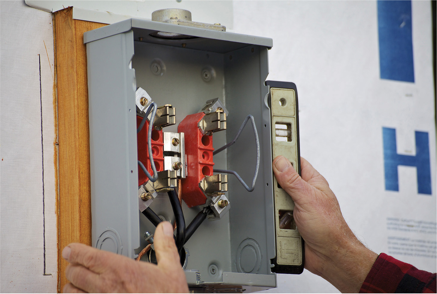
FIGURE 4-2 The utility will have definite ideas regarding meter location. It is central to the design of the service.
Building the Temporary Service
Almost all new construction projects and many remodeling projects require a temporary service, as shown in Figure 4-3. The purpose is to provide workers with electrical power needed to build the foundation and to do whatever work is required to construct the building to the point where it is possible to have an energized entrance panel inside. This usually involves having a roof on the building so that there will not be water damage to the electrical equipment. The temporary service is generally aerial, even if the permanent service is to be underground. The temporary meter and entrance panel are mounted on a wooden pole. The main object is to get the weather head high enough above grade so that when the utility connects its triplex about 16 inches upstream from the weather head, there will be sufficient ground clearance at every point along the line to the transformer. The temporary pole is usually 16 feet long. It may be 3 feet in the ground with 13 feet above grade. This should be high enough to get 12-foot ground clearance for the line from the temporary pole to the final utility power pole because the utility-owned triplex rises sharply as it runs toward the transformer. But this is not always the case. There may be a knoll or rise in the grade along the path, so it may be necessary to use a longer pole, make an extension at the top, or set it farther out of the ground. If this latter alternative is chosen, the pole should be braced to the ground, paying particular attention to the fact that the top of the temporary pole will try to move toward the utility pole because of the weight of the triplex, especially in winter, when there may be additional ice loading. Where it is impossible to maintain ground clearance, an alternative is to consider relocating the temporary service. All this should be worked out in advance with the utility representative.

FIGURE 4-3 A temporary service. The two GFCI circuits need to be connected, and then it will be time to call the utility.
Do not attach the temporary service equipment to the pole prior to setting it, and remove it prior to taking the pole down. Otherwise, you are asking for trouble. The temporary pole is generally 6- × 6-inch pressure-treated lumber, but a segment of old telephone or power pole should be acceptable to the utility and electrical inspector.
Most electricians have two or three temporary services on hand so that separate jobs can be powered up simultaneously. They rent out these temporary services, and this may be the way to go because it will be cheaper than building a new temp, so you should price out both options. A rented temporary service will not include the pole.
To build a temporary service, proceed as follows: the backing board should be 2- × 12-inch pressure-treated lumber. Gone are the days of plywood, which gets ragged and delaminates when the edges are exposed to weather. It is best to assemble the temporary electrical equipment first before cutting the backing board so that it will be long enough. There should be room at the top to secure the service-entrance cable to avoid strain at the meter, particularly when transporting the temporary service between jobs. Also, be sure that there is plenty of room at the bottom for receptacles.
To assemble the temporary service, start with the meter socket. This is an expensive item, but sometimes the utility will donate a new or used one, complete with weatherproof hub. Be sure that the meter socket is the aerial type, not for underground services, and that it is a 100-ampere service instead of 200-ampere service unless it is an unusually large construction job.
Assemble the service equipment except for the service entrance cable, and mount it to the backing board prior to attaching the backing board to the temporary pole. The temporary service will have a more professional appearance if you make two diagonal 1-inch cuts at the upper corners of the backing board. At the top of the meter socket, you need a hub with waterproof connector, which has to be bought separately. Without this hardware, water will leak in and spoil the electrical connections. Assemble the breaker box to the meter socket. If the backsets of the two knockouts are the same, you can use a short length of metal raceway. If they are different, an offset nipple is needed.
Bonding the Raceway
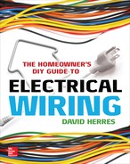
Because it is a service, this piece of metal raceway has to be specially bonded, beyond two locknuts at the meter socket end. For this redundant bonding, the inside locknut has to have a grounding lug, as shown in Figure 4-4. Take off this lug in order to tighten the locknut; then put it back on. The locknut has to be tightened sufficiently to dig into the paint on the inside of the box to ensure ground continuity. With this arrangement, where there is not a threaded boss, you must have an insulating bushing on the end of the threaded raceway, and you have to remember this before making up the wire terminations.
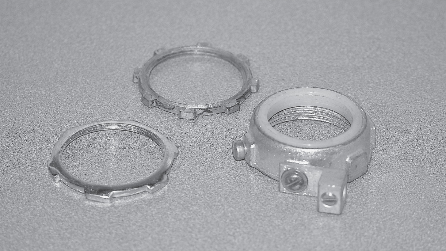
FIGURE 4-4 A bonding bushing with a ground lug connected to the grounding conductor is required for redundant bonding. It is usually located in the meter socket enclosure.
Ground-Fault Circuit Interrupters, Of Course
Assemble two outdoor cast-aluminum receptacle enclosures, commonly called bell boxes. You will need ground-fault circuit interrupter (GFCI) covers that are rated for use outdoors when cords are plugged into them to prevent water damage to the GFCIs. Use threaded offset nipples coming out of the bottom of the breaker box and into the top of the receptacle enclosures. Bonding locknuts are not required because these raceways are downstream from the overcurrent protection and are technically not part of the service.
Now that the four boxes are assembled, we are ready to mount them to the backing board. Use galvanized screws, and arrange the boxes precisely so that everything will be straight and plumb.
The next task is to wire the boxes, except for the service-entrance cable, which is hooked up after the backing board is attached to the temporary pole. First, connect the ground-electrode conductor at the meter socket. Most electricians provide a 2-foot whip outside the box so that between jobs they don’t have to deal with the long piece. Use 6 American Wire Gauge (AWG) bare or insulated stranded copper wire. Thread an end through the miniature knockout on the bottom of the meter socket. No connector or sealing is required here because water should drain freely in the event that it finds its way into the enclosure. Bring the grounding-electrode conductor through the grounding-bushing lug and onto the meter-socket ground lug. Tighten these connections thoroughly so that if there is heavy fault current, they won’t arc.
Next, wire the two bottom phase lugs in the meter socket. Then go through the offset nipples to the main breaker input lugs. Use Type THHN copper conductors of the required ampacity. You can use larger wire if it will fit in the main lugs.
Then insert two single-pole 20-amp breakers into opposite sides of the breaker box. Be sure that they are on opposite phase bus bars so as to balance the load. Using Type THHN 12 AWG black or red copper conductors, wire the breakers in this small service panel to the two GFCIs. Using white Type THHN 12 AWG conductors, wire the neutrals. Use bare or green wire of the same type to connect the equipment-grounding conductors. Check that the main bonding jumper is in place because this is a service panel.
Mount the backing board onto the temporary pole. Use galvanized lag screws so that it can be removed easily when the temporary service is taken down. Drive a ground rod nearby. Use a split-bolt connector to add enough 6 AWG ground wire to reach the ground rod. The ground wire should be stapled lightly to the temporary pole and then buried over to the ground rod. Connect this wire using a ground clamp.
At the top of the meter socket, the hub and connector with a watertight rubber seal should be in place. For the cable, use Type SE (service entrance), which is available in copper or aluminum. Copper is better, but everyone uses aluminum in this application because it is much less expensive. If you are using aluminum, choose 2 AWG (not 2/0 AWG) for a 100-amp service. For copper, the next smaller size, 4 AWG, is permitted because it has the same ampacity. Type SE is known as concentric cable because there are two ungrounded conductors inside a woven bare grounded conductor that is the neutral. This cable is quite safe because the grounded neutral is similar to a metal raceway. For service-entrance conductors, this extra protection is essential because the only overcurrent protection, at the utility transformer, is at a very high level. Even with a direct phase-to-ground short circuit, it won’t trip out.
Make It Watertight
Run the Type SE cable through the watertight connector, leaving a long-enough end. Using cable fasteners, secure the cable to the backing board and up the pole to the top. Then go back and tighten the watertight connector. This compresses the rubber and makes it grip the cable so that water will not run down inside. Just to be sure, apply a ring of silicone caulk at this connector.
At the top of the pole, install a weather head, fastening it to the pole using a removable lag screw. Be sure to run the neutral through the middle hole and the two hot phase conductors through the outer holes. To do this, slit the outer jacket and remove the scrap and the plastic strip. Separate the woven neutral from around the two ungrounded conductors, and twist the strands to make a single well-formed wire. Leave about 16 inches of each conductor including the neutral beyond the weather head so that the utility has plenty of wire to work with. The utility worker will form the wires to make a drip loop, strip the ends, and crimp them to the triplex to make an electrical connection. The utility worker also will provide a strain relief, lagged into the pole, so that the triplex does not pull on the weather head.
Back at the meter socket, inside the enclosure, slit the Type SE outer jacket, unbraid the neutral so that it no longer surrounds the ungrounded conductors, and twist it to form a single conductor. Terminate the grounded conductor at the neutral lug and the two hot ungrounded phase conductors at the two phase lugs. Form the wires inside the enclosure to make gentle loops as opposed to straight bars going to the lugs so that thermal motion doesn’t compromise the connections. To make the phase and neutral connections, it is best to remove the lug screws with contacting plates, lay the stripped ends in place, and then replace the hardware. All service terminations, especially if the conductors are aluminum, should be quite tight.
Special Techniques for Aluminum Terminations
Aluminum terminations have the disadvantage that they are prone to failure if not done correctly. For this and other reasons (such as conduit fill), in short runs where cost is not decisive, copper is used. If an aluminum connection is made, over a period of time, the aluminum seems to flow away from the mating metal surface. Eventually, the electrical connection will begin to heat up, especially if there is heavy current. This sets the stage for corrosion, less conductivity, more heat, more corrosion, and so on until there is at best an outage and ruined lugs and wire ends and at worst an electrical fire.
The remedy is to use corrosion inhibitor on all aluminum terminations. Follow the directions on the container. Wire brush the stripped ends and inside the lugs. Be sure that there are no insulation fragments that could get caught between mating surfaces. Beyond the electrical connection, there should be at least ¼ inch of wire so that the lug does not tend to expel the conductor when it is tightened. Be sure to tighten the connections correctly. Use the manufacturer’s specifications and a torque wrench.
Check all terminals with your ohmmeter. With no connected loads, there should be no continuity between the two legs or between either leg and ground. However, there should be continuity between the equipment-grounding conductor and the neutral and all metal enclosures and the grounding-electrode conductor.
Replace the cover on the meter socket. There should be a cardboard closure pad that goes in the meter-socket opening. The utility may give you a reusable plastic shield that works quite well. Review the entire installation. If everything looks good, call the utility to have it heat up the temporary service.
Soon it will be time to build the permanent service, switch over the power, and decommission the temp. At most, there will be no more than a few minutes that the building is without power.
Electrically, the permanent service, shown in Figure 4-5, is the same as the temporary service. The physical layout is different because it is attached to the building. There is a great variety in types of permanent services, with many kinds of hardware available. You have some freedom to improvise, within limits set by the National Electrical Code (NEC), the utility, and the local jurisdiction. Throughout, remember that there is tremendous available fault current without the usual overcurrent protection.
FIGURE 4-5 This meter socket is in back-to-back configuration with the entrance panel on the inside of the house. The polyvinyl chloride (PVC) conduit coming out of the bottom of the meter socket contains the grounding-electrode conductor.
Building a Service
Learning to build a service is greatly facilitated by the fact that you can drive around any suburban neighborhood and view many types of services. A good part of each one is hanging on the outside of the building, where it may be scrutinized by the inquisitive worker without ever setting foot on the property. A digital camera will permit assembling a collection that may be put into a folder on a computer. Together with the utility book of specs, the NEC, and suggestions in this book, any type of service should be doable.
There are two subcategories of the permanent service—aerial and underground. Inside the house, they are identical, but the outside physical layouts are different. The underground service is more expensive, but it has some advantages, aesthetic and otherwise. Because there is no overhead service drop to impede the view, the property has a less cluttered appearance, and in the end, the real estate becomes a more valuable asset. Without a weather head and service-entrance cable attached to the exterior wall, the building, often with a gable end facing the road, has a more stately appearance. Where the aerial cable crosses the yard, the utility has an easement whose width may be substantial, and this can affect use of the property. Local septic regulations often prohibit a tank and leach field within this easement, and for a small lot, this may limit options. With an underground service, it is permissible to wind around to an extent as long as the bends are large-radius sweeps. If the home crafter-electrician does the labor and reasonable backhoe arrangements are possible, an underground service is feasible, and it will be much appreciated in years to come.
We shall look at both types of service from the construction point of view, beginning with the aerial service. In the course of the initial meeting with the utility engineer, a meter location will have been determined, perhaps with a range of options for the property owner. The utility wants the meter to be in an easy location to read, preferably without the reader having to leave his or her vehicle. This is true even if it is a “smart” meter because you never know when the remote communication will become problematic. The utility will want the meter protected from damage, on the gable end rather than the eave side, where there is a possibility of falling ice, and located so as to accommodate straight-line connection to the transformer. Additionally, the utility will want an eye-level height for ease of reading, which translates to a height of 5 feet above the grade. Don’t forget to allow for any deck or addition that may be built. Other than these requirements, the meter location is essentially up to the homeowner.
Masthead Service Construction
Materials for the masthead service are a little more expensive, and more labor is involved. In this configuration, the meter is located on the eave side of the house, which is necessary for mansard or double-hip-roof construction, where there is no gable end. This location is also used where the gable end is not high enough to provide minimum ground clearance for the service drop.
Meter placement is affected by a strong NEC mandate that applies to the inside portion of the building. It is stated that the main disconnect must be located closest to the point where the service-entrance conductors enter the building. The mandate calls for some interpretation because, if nothing else, there will be the thickness of the wall to consider. Nevertheless, a back-to-back pattern is invariably acceptable and is in fact the best. This construction involves removing large knockouts on the backs of both entrance panel and meter socket, inserting a straight threaded conduit whose length is equal to slightly more than the thickness of the wall, and passing the service-entrance conductors through that short raceway. Exposure to damage for these conductors is minimal.
Service Variations
For other setups, the precise permitted separation will be a matter of interpretation for the electrical inspector. As much as 12 feet is sometimes mentioned as a rule of thumb. The installation will be seen in a more favorable light if the conductors are run in a metal raceway. In a problem site, contact the electrical inspector prior to construction.
Often in slab construction, where there is no basement, the back-to-back configuration works well, even though the entrance panel may have to be a little lower than the optimum eye level. This is not a Code violation.
When there is a full basement, there may be a problem in locating the entrance panel because of various factors, such as the location of a fuel tank or water piping. Also, the entrance panel, because it contains overcurrent devices, may not be located in a bathroom, clothes closet, on a stairway, or anywhere that there is not sufficient working space or dedicated space above.
In some buildings, any of these factors may severely limit placement of the entrance panel. One way to work around the Code mandate mentioned earlier is to have a main disconnect that is separate from the entrance panel. Then, because they are overcurrent protected, the conductors to the entrance panel become a feeder, which can be placed anywhere on the property. In this case, you can use what is called a main-lugs-only breaker box. It has no main breaker and is no longer an entrance panel, becoming what is known as a load center. Of course, if you already have a box containing a main breaker, there is no harm in that. In such a construction, we must stress that there is to be no main bonding jumper in this box. Instead, it is located in the main disconnect enclosure. The feeder, then, has four wires, including the green equipment-grounding conductor.
The remote main disconnect makes for a more expensive installation and is less convenient, but for some sites, it is necessary to comply with the NEC mandate mentioned earlier. The main disconnect is available as an outdoor unit, and this is necessary in some cases.
In view of these considerations, you have to determine good entrance panel, main disconnect, and meter locations before proceeding with the service. In some remodeling jobs, the temporary meter occupies the space where the permanent meter has to go. With a little advance planning (leaving extra slack in the service entrance and grounding-electrode conductors), it is possible to swing the temporary meter off to the side so that the permanent meter socket can be mounted in place and wired.
To do a new gable-cable aerial service, if it is a back-to-back installation, first use a hole saw to drill a hole in the sheathing. This hole should be about ⅛ inch larger than the outside diameter of the threaded conduit that is going to attach to the back of the meter socket and the back of the entrance panel. So begin by checking the sizes of these two knockouts. They may not be the same.
These knockouts may be offset from the center in one or both boxes, so the whole thing has to be laid out paying attention to the locations of any studs that may block the hole, how the entrance panel door is to swing, whether backing boards are to be installed inside and out, and similar considerations. If the siding is not yet on the outside wall, you may want to make a pine backing board for the meter socket. It should be about 1 inch bigger all around. On the inside, is the entrance panel flush-mounted between studs or surface-mounted on the finish wall? You have to think about numerous issues, such as whether it will be possible to take out the knockouts and add connectors and wiring in the future if the entrance panel is close to studs. One solution, in a finished living space, is to provide a backing board for a surface-mounted breaker box and then (later) build a cabinet around it with a good-finish access door.
The following discussion presupposes that you have read the section of this book on temporary services, especially the parts about bonding service equipment to metal raceways and use of corrosion inhibitor with aluminum conductors. With the hole drilled and the boxes set in place, measure the length of the threaded conduit nipple that you will need. This is a difficult measurement to make because you have to have enough threaded ends at both boxes to accommodate the bonding locknut at the meter socket, the locknut at the entrance panel, and the insulating bushing. It is recommended that you do your best to get an accurate measurement and then obtain the next sizes longer and shorter as well.
One of the advantages of the back-to-back arrangement is that the two boxes hold one another tightly to the wall even without the mounting screws, which nevertheless should be used to keep the boxes from turning. The other advantage is that there is less clutter inside and out. The service-entrance conductors are invisible. Before installing them, it is best to complete the grounding.
Grounding-Electrode System
A number of grounding-electrode options are available. Some of them are
• Metal underground water pipe. This must be in direct contact with the earth for at least 10 feet. The problem with this type of grounding electrode is that increasingly polyvinyl chloride (PVC) is being used. Even with a metal pipe, you never know whether plastic has been spliced in, rendering the water pipe grounding electrode ineffective.
• Metal frame of the building where at least one structural member is in direct contact with the earth. This choice is not available in wood-frame residential buildings.
• Concrete-encased electrode. This is to be at least 20 feet of either one or more bare or zinc-galvanized or other electrically conductive coated-steel rebar no less than ½ inch in diameter. If there are multiple pieces, they may be connected by the steel tie wires. Metal segments must be encased in 2 inches of concrete. This is called a ufer, and it is highly effective, but it won’t be available unless provisions were made at the time the concrete was poured.
• Ground ring encircling the building. This must consist of 20 feet of bare copper conductor not smaller than 2 AWG.
• Ground plate with 2 square feet of surface exposed to exterior soil. This is generally copper, at least 0.06 inches thick.
• Ground rods 8 feet long. These are generally made of steel, copper coated, or galvanized.
In most new construction, ground rods are used. The NEC specifies that ground resistance must be measured, and the resistance of the ground rod to ground must be not more than 25 ohms. Unfortunately, ground resistance cannot be measured directly with an ohmmeter because this would presuppose the existence of a grounding electrode for reference having a ground resistance of substantially zero, in which case there would be no point in going further. Expensive equipment with elaborate procedures will measure ground resistance, but the NEC provides an alternative—an exception states that if a second ground rod is installed, it is not necessary to take the resistance measurement.
Most new residential construction makes use of two ground rods. When this is done, the rods must be at least 6 feet apart so that overlapping ground potentials do not reduce the overall effectiveness. If bedrock is encountered, it is permissible to drive the round rods at up to a 45-degree angle or to bury them in a trench with 24 inches of cover material. Under no circumstances should a ground rod be cut short.
The grounding-electrode conductor must be attached by means of a ground-rod clamp, never a hose clamp or improvised means. The grounding-electrode conductor should be run first to the near rod and then to the far one. This wire should be buried to prevent damage and for increased grounding. Both rods should be driven below grade so that the whole system is out of sight.
From the meter socket to below grade, the grounding-electrode conductor must be in a raceway. If the raceway is metal, at the bottom end it must be bonded to the grounding system. For this reason, most electricians use PVC conduit. This piece must have a two-point offset bend, as shown in Figure 4-6, so that beginning about 6 inches below the meter socket, it points toward the wall and then turns again at the same angle but in the opposite direction so that it runs along the wall down to a level several inches below grade. This is always the way to run raceway offset bends so that the raceway hugs the wall or ceiling as opposed to flying through the air.

FIGURE 4-6 PVC conduit for the grounding-electrode conductor can be bent by hand after heating it over a charcoal grill. (Practice on scraps first!)
In small diameters, PVC conduit can be bent using the next-size-larger electrical metallic tubing EMT bender. Bend the pipe twice as far as the desired angle, and it will spring back as needed. The other method is to use heat to soften the PVC conduit sufficiently so that it can be easily bent by hand. Don’t use a propane torch because it will scorch the outside without heating the inside. When you try to make the bend, the pipe will kink, substantially reducing the inside diameter. There is a professional electrician’s tool that resembles an electric blanket; it fastens around the pipe and heats it evenly, doing a nice, clean job. The problem is that the tool is very expensive, and the element is prone to burning out. There are some PVC heat benders that work off an automotive exhaust, but who knows what the petroleum residue will do to the wire in the long run? I have had good results holding the pipe about 16 inches above a charcoal grill, turning the pipe and moving it lengthwise to get the heat where you want the pipe to bend. Practice on scraps.
The PVC pipe is cemented to a threaded adapter and fastened through the appropriate knockout using a locknut. Secure it to the wall below the offset using conduit fasteners. Run the grounding electrode through the PVC conduit, into the meter socket, and through the bonding locknut, terminating it at the grounding lug.
Recent NEC editions require an intersystem-bonding terminal. Using a split-bolt connector, tap a segment of 6 AWG bare stranded ground wire onto the grounding electrode, and bring it out through the miniature knockout with no connector. Run the ground wire a short distance with no bends, and attach an intersystem-bonding terminal, which is fastened to the outside wall. It has a removable cover, and the purpose is to allow other trade workers such as telephone and satellite dish installers to bond their ground wires to the building’s overall grounding system. It is a long established principle that all grounding systems of a building must be bonded together because this prevents dangerous voltage potentials between them. Some people feel that this bonding could call lightning into the building, but this is not the case.
Wire the meter socket to the entrance panel. In a back-to-back configuration, Type THHN copper works well. For 6 AWG and larger wire, all three conductors are permitted to have black insulation because it is not feasible to carry around separate reels of each color. There is no identity between the two hot legs, so it doesn’t matter if they cross over between meter socket and entrance panel. The neutral, however, absolutely must not be confused with a hot phase wire or there will be a terrible arc flash when the utility worker attempts to insert the meter. The black neutral must be reidentified at both ends. The ends can be painted, but a better method is to use phase tape. This resembles electrical tape but is available in several colors, including red, white, and green. Wrap the correct color close to the stripped end of the conductor. The reidentifying means must completely encircle the conductor. Some electricians make three rings, but one is sufficient.
Reidentify both ends of the neutral using white phase tape. Then hook them up. Afterwards, run and terminate the hot phase legs. Check the installation with your ohmmeter to make sure that there are no shorts.
Some utilities furnish the cable that goes up the side of the building, and they also furnish the weather head. Most do not, so this segment is left to the owner.
Wires from the meter output lugs to the main breaker and from the meter input to the weather head are both the same size unless one is copper and the other is aluminum. They may be different types, for example, Type THHN separate conductors through a raceway from the meter socket to the entrance panel and concentric cable (Type SE) up the side of the building. They are different types of wire but are sized using the tables in NEC Chapter 3.
Service Sizes
For residential work, the most common service sizes are 100 and 200 amperes. A 100-ampere service calls for 4 AWG copper or 2 AWG aluminum. A 200-ampere service requires 2/0 copper or 4/0 aluminum. These are the sizes to remember. Some electricians like to use an intermediate size such as a 150-ampere service.
In all but the largest houses, a 200-ampere service is more than adequate, even with electric heat and a workshop with an arc welder and power tools. In a small cottage, a 100-ampere service is often installed, only to find as years pass that electrical use increases and a service upgrade is needed. This is a costly process because you have to replace not only the entrance panel but also the service-entrance conductors and weather head as well. And it is likely that the branch-circuit conductors will have to be extended to reach the breaker and grounding terminals inside the larger box.
It is interesting to note that a 200-ampere service is actually more energy efficient than a 100-ampere service. Devices such as breakers, wire nuts, and conductors are not considered to be consumers of electricity, but with so many gathered in a small volume, together they emit some heat, which makes the meter turn. A 100-ampere entrance panel, heavily loaded, will feel warm to the touch. A 200-ampere entrance panel will run cooler because all the devices, terminations, and conductors are larger with less I2R loss.
A variation of the gable-cable service is the gable-conduit arrangement. This makes a neat job, and the service-entrance conductors are well protected. Raceways can be PVC or EMT. Conductors are Type THHN, usually aluminum because this is a long run. Be sure to use the weather head designed to go with the raceway. It clamps onto the pipe rather than gripping the concentric cable.
Both gable-cable and gable-conduit types do not necessarily have to go to the peak of the house. Just run them high enough to get the required ground clearance. Sometimes the building has a low roof, and it is not possible, using the services described earlier, to achieve the proper ground clearance for the triplex service drop. This also has to do with the terrain between the building and the utility pole. A small knoll under the cable right where there is maximum sag can reduce ground clearance. When it comes to ground clearance, there are obviously important safety concerns.
Where the building is not high enough to accommodate a conventional service, the masthead type is the way to go. A metal raceway comes out of the top of the meter socket, penetrates the soffit and the roof, and rises to a height sufficient so that ground clearance is achieved. A masthead service should not be considered if it is not necessary for the service drop ground clearance or to locate the meter on a gable side. It is more expensive in materials, and the soffit hole and roof penetration, including the leakproof roofing job, mean a lot of extra work.
The soffit hole must be accurately positioned with respect to the meter location, taking into consideration the backset of the meter hub. If this hole is at all out of position, the raceway above and below the roof will not be vertical. A good way to proceed is to temporarily fasten the meter socket in place at the usual 5 feet above grade. Then use a plumb bob to find the center of the hole-saw cut in the soffit. When you get a little further along, you can shift the meter location a slight amount if necessary.
For the metal raceway, rigid metal conduit (RMC) is used, not water pipe, which would be a Code violation. The outside diameter and threads are identical, but RMC has a smoother inner surface so that the conductors are not damaged, and they are easier to pull. Ordinarily, a 10-foot length of 2-inch RMC will suffice. If not, the RMC is available in 20-foot lengths, which can be cut down as needed. Also, couplings can be obtained. Where the raceway goes through the roofing, a rubber boot or flashing will ensure a leakproof penetration.
The NEC states that no foreign wiring or other paraphernalia is to be attached to the masthead and certainly not run down the raceway along with service-entrance conductors. Very often telephone installers anchor their drop onto the electrical service masthead, and this is a definite Code violation.
At the top, use a compatible weather head, as shown in Figure 4-7. Fish in Type THHN aluminum conductors sized as for any other service. The utility will crimp onto the 16-inch conductor ends that you leave sticking out of the weather head. Grounding and wiring into the entrance panel or main disconnect are identical to those of other services.

FIGURE 4-7 A weather head, available in metal or PVC, is used at the top end of an aerial service, cable gable, or masthead.
Underground Services
Underground services are somewhat more expensive to build, but they contribute to making an upscale building. There is no service drop to impede the view and no service-entrance cable or weather head to clutter the finish wall. With a back-to-back meter and entrance-panel hookup, the underground service makes for a simple and elegant final product, and it will enhance the value of your real estate.
Generally speaking, a backhoe is needed to dig the trench from the utility pole to the meter location. The question that always arises is, how deep does an electrical line have to be buried? To answer this question, refer to NEC Table 300.5.
Assuming that it is a back-to-back configuration, the underground hookup is quite simple, although more labor is involved than for an aerial service. The consultation with the utility representative will nail down the details. Generally, the customer digs the trench and furnishes the underground run of conduit, cemented with a pull rope in place.
The conduit should be installed as a complete system, hooked up to the meter socket, and the trench backfilled and graded. The utility usually furnishes the service lateral conductors. The utility pulls them through the conduit and makes the terminations.
The telephone line should be buried in the same trench with maximum separation from the power line. Use 2-inch PVC with sweeps and a pull rope. Leave stubs 1 foot above grade at both ends. The telephone company, subject to prior consultation, will pull in its line, put an interface box on the wall, and make all terminations, including bonding to your intersystem-bonding terminal.
If the soil is at all rocky, the conduit should be bedded in screened sand to a height of 6 inches above the conduit. Then another 6 inches of native fill is added by hand to make sure that no big rocks damage the conduit. If you place the conduit against the edge of the trench and machine backfill from that side, there is less exposure to damage.
The service lateral remains the property of the utility, and if there is a problem in the future (such as lightning burnout), it is the responsibility of the utility to make the repair. Because the service lateral is in conduit, it can be replaced even if the ground is frozen with no digging required. For this reason, even if the conductors are rated for direct burial, they are always put in raceway. PVC is the conduit of choice for almost all underground work. In consultation with the utility, you probably will use steel 90-degree sweeps and expansion joints to allow for ground movement if subject to freezing.
At the building, place the sweep so that the stub will come up perfectly plumb with the meter-socket knockout. You can finish this prior to drilling through the building for the back-to-back stub so that the meter socket location can be adjusted laterally to make for a straight riser.
The expansion joint should be put in with the outer part of the slider at the top so that it will shed water. Position the expansion joint midway between maximum and minimum length. Grounding and wiring to the entrance panel are the same as for an aerial service.
At the utility pole, details should be worked out in advance. Typically, to a height of 8 feet above finish grade, Schedule 80 PVC is used. (All other PVC is Schedule 40.) Because the sweep contributes some rise, a 10-foot length of Schedule 80 PVC ordinarily will do. Most utilities want to see this piece installed by the electrician. Then the utility furnishes the rest of the run, using Schedule 40 PVC up to the transformer, where there is a weather head and a strain relief with a drip loop.
Regardless of the type of service, the back-to-back arrangement of meter socket and entrance panel or main disconnect is preferable. There is less clutter inside and outside the building, and minimal conduit and wire are needed to get into the building. Moreover, both boxes are held very firmly in place and will never work loose.
Sometimes, usually because of the vertical layout of the building, a back-to-back configuration is not possible. In such cases, we have already mentioned the need to install a separate disconnect if the indoor portion of the service-entrance conductors are of any significant length.
In a non-back-to-back installation, the service-entrance conductors can be run as Type SE concentric cable or in a raceway. If cable, it is best to come out of the meter socket at the bottom. Such an arrangement is preferable because water infiltration is not an issue. It will drain straight out of the bottom.
Where the cable enters the building, a small piece of hardware known as a sill plate is used. It is sized to fit the cable. The cable should enter the sill plate from below so as to shed water. Fill around the cable with silicone caulk.
These conductors also can be run in a raceway. PVC, RMC, or EMT can be used. PVC conduit (gray UL listed, never white PVC water pipe) should not be used in long horizontal runs on the outside of a building because thermal changes will make it sag and buckle. EMT, if used outdoors, must have compression fittings. Set-screw fittings would allow water to enter, and they are used indoors only.
Ordinary 90-degree bends, as found in water systems, are not used in electrical raceways. Instead, pull boxes are needed, as shown in Figure 4-8. These fittings have removable plates, making it much easier to pull the conductors.

FIGURE 4-8 An LB, available in metal or PVC, is used where an underground service lateral enters the building.