
CHAPTER 10
![]()
Tackling Difficult Projects
A color TV is an enormously complex piece of equipment in a small box. Of necessity, it is tethered to multiple vast broadcast infrastructures. For this reason, it got off to a slow start. Without transmission, there could be no reception, and without reception, transmission would be pointless. Even black-and-white TV didn’t become much of a reality until well into the post–World War II technology boom, and color TV did not become universal until after the mid-1960s.
Color TV Protocols
For color TV, shown in Figure 10-1, to work, there has to be a protocol that is shared by the broadcast and reception equipment. This shared method of operation goes way beyond the audio and video signals.

FIGURE 10-1 A flat-screen color TV.
A lot of it has to do with the scanning procedure. The analog broadcast system in use in North America is known as the National Television System Committee (NTSC). The principal parameters are
• Lines: 525
• Fields: 60
• Horizontal frequency: 15.734 kHz
• Vertical frequency: 60 Hz
• Color subcarrier frequency: 3.579545 MHz
• Sound carrier: 4.5 MHz
For this to work, scanning has to be synchronized between transmitter and receiver. This information must be included as part of the transmission.
What we want to do in this chapter is to introduce some of the basic concepts that underlie color TV troubleshooting and repair. It is way beyond the scope of this book to provide more than an introductory overview. TV technicians know that this work is a very long-range undertaking. As new and more difficult repairs are undertaken, the body of knowledge expands. Technology is also advancing at a rapid pace, so new troubleshooting and repair methods mean that the focus is always shifting. An example is the seismic analog-to-digital upheaval, which has had great consequences for the professional. Despite all of this, we might as well dive in because it is only your old TV that is at stake.
An Inherent Hazard
That being said, it is a grave mistake to approach this work with a totally relaxed and casual attitude for the simple reason that some of the components are capable of storing lethal voltages long after the TV has been disconnected from the power source.
To begin with the older type of TV set that has a cathode-ray picture tube, to make the picture, a beam of electrons is emitted from a cathode, which is heated by a filament at the rear of this large vacuum tube. The stream of electrons is accelerated toward the screen, where they would make a very bright static spot in the center if it were not for the deflection coils (electrostatic deflection plates in an oscilloscope) that persuade the beam of electrons to scan the screen, side to side and top to bottom. In order to deflect the beam of electrons, high voltages are needed. Inside the TV, a number of different voltages are derived from the 120-volt utility-supplied power. Included are the high deflection voltages.
Among the many components in the TV are electrolytic capacitors. They resemble large cylindrical plastic or metal cans with wire leads or spade terminals. Electrolytic capacitors are also used in motors, either externally or internally, for the start and/or run circuits. Electrolytics are similar to other capacitors, except that they have a very high capacitance and working voltage. The dielectric layer that separates the two plates is not a physical layer of insulation, but instead, it is formed electronically when the voltage is applied. A thin dielectric layer equates to high capacitance, and that is what is needed in power-supply circuits.
Once voltage is applied, the electrolytic capacitors hold the charge for a very long time unless there is a parallel resistance to bleed out the voltage. The lower the resistance, the quicker the voltage will drop. Every capacitor with a parallel resistance has a time constant. What all this means is that when you open a TV cabinet, even if the set is not plugged in, you can really get nailed if you are not very careful.
First, some preliminary precautions are in order. The workbench should be a dry (not oily), clean insulating material such as smooth wood or plastic laminate. You should sit on a nonmetallic stool or stand on a heavy, dry rubber mat or similar nonconductive surface. Receptacles with grounded metal faceplates should not be located along the front edge of the bench but instead along the wall a few inches higher than the bench level where they cannot be accidentally contacted.
Set the TV on the bench, hook up an incoming signal via coaxial cable, and power up the set. Carefully note any symptoms. Is the set completely dead? See if there is a power light that comes on. Even if the screen is completely dark, it is usually possible to sense the presence of voltage by faint light or sound. You may hear a low-level alternating-current (ac) hum coming from the speaker. If there is no sign of life, inspect the power cord from plug to cabinet. Using a tool with an insulated handle, gently tug on and move the cord from side to side where it enters the cabinet.
As a matter of course, use a neon test light to make sure that the chassis is not hot. Most modern TVs have few conductive parts on the outside, but you should be able to pick up a connection to the chassis through the head of a metal screw or the outer shell of the coaxial connector.
Then power down the set by unplugging the cord from the receptacle. Disconnect the coaxial cable signal feed. If, at any point, it is necessary to tip the set forward so that it is resting on the screen, it is permissible to lay it face down on a soft, folded blanket on the bench.
Remove the back from the set. This will disconnect the power cord. TV technicians, of necessity, use a cheater cord to bypass this safety feature so that the set can be run out of its case. They place the TV so that the screen is facing into a large mirror, and in that way, they can work at the back of the set while watching the results. Do not power up the set outside the case unless you have the training and experience to perform this operation safely. Remove any screws that are holding the chassis, and slide it out of the case. Here is where you have to be careful not to contact conductors or terminals that are energized.
Many technicians shunt out the electrolytic capacitors and the high-voltage screen anode (in an analog set) to ground using a screwdriver with an insulated handle or an insulated jumper wire. This is a bad practice because the abrupt current surge can damage the capacitors and other components. It is better to use large low-resistance power resistors with flexible leads connected to insulated alligator clips. Do not remove the chassis from the cabinet unless you are certain that you can find all the high-voltage terminals and safely discharge them. This process has to be repeated after each power-up. The deflection voltages can reach 30 kV, so great care must be taken.
Preliminary Diagnosis
If you are not an experienced TV service technician, you will be limited as to the types of repairs that you can do. But, by the same token, if the set is completely dead, the possible faults are limited, and troubleshooting, diagnosis, and repair are doable using ordinary electrical tests and repair methods.
First, with the set powered down (unplugged, not just turned off) and all hazardous voltages discharged, visually inspect the area where the power comes into the cabinet. Using an ohmmeter, check each of the power-cord conductors individually, going from the external plug to any power switch, fuse, or other termination. Even without a schematic, you should be able to follow the power flow to the transformer primary. The transformer is a large, heavy laminated steel component, often with cooling fins.
Disconnecting leads as needed to eliminate any parallel current paths, check out the primary and secondary windings of the power transformer with your ohmmeter. The secondaries may be separate windings or multiple taps on a single winding, providing different ac voltages to be rectified and filtered to make direct-current (dc) bias voltages for the solid-state devices and the picture tube.
When disconnected from any possible parallel loads, the individual windings all should read low resistance. Moreover, all leads or terminals should be isolated from the transformer core when none of them is connected to the chassis ground or when the transformer is unbolted and lifted so that it is not grounded.
The bottom line is that if any of the windings are open, the TV won’t work. Also, some turns could be shorted internally, altering the output voltage. If primary turns are shorted, it will raise the voltage. If secondary turns are shorted, it will lower the voltage. Because the transformer is not repairable, if it is bad, it will have to be replaced.
Working on a live chassis that is out of the enclosure takes lots of knowledge and nerves of steel, so if you do not have an abundance of both, you will want to limit yourself to some ohmmeter readings with the set powered down and all high voltages bled down to zero. On the Internet, TV service manuals and schematics may be downloaded free of charge, so you will want to obtain this documentation for the TV on which you are working.
In the schematic and a pictorial diagram that is part of the documentation, find the power-supply components, and then locate them on the chassis. The primary parts of the power supply are the diodes that comprise the full-wave rectifier and the electrolytic capacitors that are also part of this network. If any of these parts are not working, the television will not work.
The way to proceed is to visually inspect these components. If a capacitor is swollen, has a distorted shape, or appears charred, it is definitely bad or will fail soon, so it should be replaced. On the other hand, it may look fine but could be defective. The same comments apply to the diodes, except that a faulty diode is less likely to appear bad. For either of these components, check the wire leads, and test them and solder joints for continuity. Specialized equipment is available for testing capacitors and diodes, but a standard multimeter will give a good go, no-go determination. Figure 10-2 shows a low-power diode and four transistors.

FIGURE 10-2 A diode has two leads, and a transistor has three leads.
To test a diode, measure the resistance. The lowest range (with the audible continuity beep) works well. Then reverse the leads and measure the resistance going the other way. The multimeter, in the ohms function, applies approximately 3 volts, derived from the interior battery, to the component being tested. A diode has two leads, a cathode and an anode. When a positive voltage is applied to the anode and a negative voltage is applied to the cathode, the diode conducts. It is said to be forward biased. When these connections are reversed, the diode does not conduct. It is reverse biased. There will be a pronounced difference in these readings if the diode is good. When a diode fails, it often shorts out. Very quickly thereafter, the fault burns itself out so that the bad diode reads open both ways.
The condition of an electrolytic capacitor also can be determined using a multimeter in the ohms mode. It may be necessary to disconnect one terminal so that the device is out of the circuit. Set the ohmmeter to a low-megaohm range for a start. Touch the probes to the two terminals, and note the reading. Then reverse the terminals and compare. You will see that the ohm reading will either remain the same or move in a very stately fashion either upscale or downscale depending on the capacitor’s state of charge and the polarity of the probes. The changing readout is very measured and distinctive. It slows as the limit is approached. This is so because the ohmmeter is either charging or discharging the capacitor. This is how a good electrolytic capacitor behaves. Electronic technicians say that the capacitor is counting. A bad capacitor will not count. A small-capacitance signal capacitor cannot be checked in this way.
Diodes and capacitors are inexpensive, and replacing them often fixes a power supply and gets the TV back in service. A good many TV malfunctions are as just described. Other problems, such as poor color, may be more difficult to diagnose and repair, and they involve skills and knowledge possessed only by a TV technician. They also involve working on a live chassis, which is not recommended for one who is not fully trained and experienced in the field. However, we may step back and observe an experienced technician at work.
The schematic may have embedded in it small graphics that show waveforms at different points. With a signal generator connected to the tuner or various other appropriate inputs, an oscilloscope can be connected at the points where these waveforms are shown. This requires some knowledge and experience, but for the electronics technician, it is a familiar operation.
The oscilloscope, shown in Figure 10-3, is a voltmeter that depicts the waveform on the screen. Properly calibrated and adjusted and with the correct probe chosen, the ground clip is connected to the chassis, and the probe is touched to successive test points indicated on the schematic, looking to see if the waveform appears as shown in the graphics. In this way, the defective stage, circuit, and component can be located. If you are interested in oscilloscopes, take a look at the many Tektronix tutorials, manuals, and data sheets at www.tek.com.

FIGURE 10-3 A digital storage oscilloscope. (Photo courtesy of Tektronix.)
Bias voltages, also indicated in the schematic, can be tested using a standard multimeter. The object, finally, is to identify the defective component(s) so that a repair can be made. All of this, of course, involves working on a live set.
A whole category of faults consists of intermittents. They come and go, raising the uncertainty level and making diagnosis difficult. Most intermittent component failures are caused by changing amounts of heat. As the temperature of a component increases, an invisible crack may open, breaking the current path or causing some other parameter to change. Typically, the set will operate when first turned on and then abruptly exhibit some type of failure.
Tracking Down Intermittents
Technicians use a product called a component chiller to make the symptom come and go. The freezing spray, similar to the ether that is used to start diesel engines and formulated so that it will not damage plastics and other sensitive materials, is directed successively at suspect components until the offender is identified. Similarly, heat can be used by holding a soldering iron just close enough to warm the component without frying it. Of course, this is a diagnostic technique only and will not repair anything.
Many electronic faults are due to what is known as cold solder joints. The solder joint, for a variety of reasons, such as insufficient heat applied at the time of manufacture, may fail days, weeks, or months later. The cure is to place a small amount of flux on the joint and remelt the solder without overheating any nearby connected components.
Another effective measure is, with the set powered down and the high voltages discharged, to pull apart each ribbon connector and slide it back in place. This will repolish the contacts that may have become corroded. Ribbon connectors age and become brittle, and if one or more conductors becomes severed or loose at a termination, the set will be adversely affected.
We have discussed some troubleshooting and repair techniques for ailing TVs. One of the requirements for success in this as well as in many other types of electronics work is the art of good soldering.
Making Good Solder Joints
At one time, all the splices in ordinary house wiring were soldered. The wires to be joined were twisted or looped together and then soldered so as to make a mechanically strong and electrically conductive joint. Then they were wrapped with two types of electrical tape and inserted, along with other similar splices, into grounded junction boxes. When done properly, this type of splice was safe and reliable. But it was time-consuming and required specialized tools and materials. Introduction of the wire nut, an equally safe and reliable solution that was quick and easy, totally eclipsed the old splicing procedure, and that is how it will remain for the foreseeable future.
Despite the fact that soldering no longer plays a role in home wiring, it still figures prominently in electronics fabrication and repair. If you are working inside a TV or other similar electronic equipment found in the home, soldering will be a necessary part of the picture. Fortunately, it is an easy skill to learn, and with a little concentrated study and practice, you can excel.
To make a good solder joint, you need to use the right tools and materials, and you need to have the right techniques. Many metals can be soldered, some more readily than others. Stainless steel and aluminum are impossible to solder without specialized methods and materials. What about brass? It depends on the alloy. Some brass solders easily, and some does not. Fortunately, almost all your soldering will be copper to copper, and that metal solders very nicely.
The best way to learn how to solder is to obtain some scraps of copper and try soldering them together. Then you can put your finished product in a vise and see if you can pull it apart. Also, test the joint with an ohmmeter, stress it severely, and test the resistance again. Similarly, remove one or more printed circuit boards from discarded electronic equipment. Break the circuit board, and then see if you can repair the fracture, soldering appropriate jumpers across broken traces. Remove and resolder components, and test them with your ohmmeter.
Soldering consists of joining the two pieces of copper by heating them sufficiently above the melting point of solder so that when the solder is touched to them, it will melt and bond to both pieces. It is unlike welding in that the two pieces of copper are not melted and allowed to mix. On the other hand, though, the solder does not just sit on the surface of the metal piece to be soldered. It is absorbed a certain distance into both the metals. This is so because copper, like other metals, is highly absorptive. Metal, when it is clean and hot, is like a hungry sponge. Given the right conditions, your solder joints will make themselves.
Solder generally comes in wire form, as shown in Figure 10-4. For electrical work, it is usually an alloy of tin (Sn) and lead (Pb). Other metals, including silver, may be added, but the usual scenario is an Sn-Pb alloy. In recent years, there has been a move away from lead. For soldering pipes in a potable-water system, lead-free solder is essential. For electrical work, the problem with lead-free solder is that it has a higher melting point. This translates into more difficulty in creating a sound joint and the possibility of component damage due to the higher temperature.

FIGURE 10-4 Wire solder for joining 12 American Wire Gauge (AWG) wire and larger.
When using solder that contains lead, you definitely do not want to breathe the fumes. Work in a well-ventilated room, and set up a small fan in such a way that it directs the fumes away from you. This is important even when using lead-free solder because, as noted earlier, metals are highly absorptive, and you never know what impurities they may have acquired during manufacture.
The interesting thing about solder alloys is that the melting point is lower than that of either of the constituent metals. The melting point of lead is 621°F. The melting point of tin is 450°F, but the melting point of an alloy consisting of 63 percent tin and 37 percent lead is 361°F, much lower than either of the parent materials. Solder is labeled by using the percent of tin, and the remainder is assumed to be lead unless otherwise stated. For example, Sn 50, used by plumbers to solder copper pipes, is 50 percent tin and 50 percent lead. For electrical work, Sn 60 and Sn 63 are the usual choices.
In order to make a good solder joint, the pieces to be soldered and the soldering-iron tip must be clean, that is, free of dirt, contamination, and an oxide coating. The oxide acts as a thermal barrier, making heat transfer impossible. If there is an oxide coating on your soldering-iron tip, you can bring it up to temperature, but the heat will not transfer to the solder. If you touch a piece of solder wire to a soldering-iron tip that has an oxide coating, the solder will crumble and break into small pieces that fall away, but it will not melt to form a liquid. If you heat a copper wire that has an oxide coating using a clean tip, the solder will melt and then just roll away from the copper wire without bonding. To solder, the tip and the pieces to be soldered must be clean.
To clean the tip, bring it up to temperature, and wipe it on a damp sponge that is kept on the bench for that purpose. This will remove the oxide coating and any dirt or contamination so that the tip will have a shiny, clean appearance. However, at high temperature, the oxide coating will immediately re-form unless steps are taken to prevent this from happening. Immediately after wiping the tip on the sponge, apply a very small amount of flux. When the flux is bubbling, it is at the right temperature. Extended heating will burn the flux, causing it to lose its effectiveness, and the oxide returns.
How to Tin a Soldering-Iron Tip
Touch a piece of solder to the soldering-iron tip, and as it begins to flow, power down the soldering iron. The solder should flow around the tip, making a protective silvery coating that will not oxidize. This is called tinning a soldering tip. It only takes a couple seconds, but it must be done prior to each soldering operation. Also, at the end of the session, the soldering-iron tip should be tinned so that it doesn’t corrode during storage and it is ready for the next job.
The pieces to be soldered also need to be cleaned. In storage, copper acquires a dull orange finish, and this is also an oxide coating that will prevent heat transfer and successful soldering. Scrape the wires or terminals gently with a knife without nicking them, or polish them using steel wool. Avoid sandpaper, which can leave sand particles embedded in the metal that will impede conductivity. Apply flux, and as you bring the copper up to soldering temperature, the flux will do the job.
Applying flux is more important than cleaning the work by mechanical means. A freshly cleaned copper surface without flux will reoxidize immediately as it is brought up to temperature, and successful soldering will not be possible.
What Kind of Flux?
The correct type of flux must be used. For electrical work, definitely do not use the acid-based flux that is used by plumbers to solder copper pipes and is used for automotive radiator work. The correct type of flux is rosin-based flux. It is nonconductive and milder, leaving no corrosive residue that would attack the solder joint or make a conductive bridge that could short out adjacent traces on a circuit board.
Flux comes in a can, and it is applied with a wood or plastic applicator. Cutoffs from installed cable ties are perfect for this use. If you prefer, rosin-core solder containing just the right amount of flux works equally well. If there is any thought that there may be contamination, after it has cooled, the joint can be cleaned with isopropyl alcohol.
Depending on the size wires or circuit board, the correct tip, solder diameter, and technique must be coordinated to achieve consistently successful solder joints. For small work, such as a circuit board, a 15-watt pencil-tip soldering iron is perfect. For larger components, 30 to 50 watts will make a good fit. If you want to solder 12 American Wire Gauge (AWG) wire or larger, a pistol-grip soldering gun, as shown in Figure 10-5, will give good results.

FIGURE 10-5 Pistol-grip soldering iron for large work.
For very small printed circuit work, 0.020-inch wire solder is the correct size. As the size of the work increases, use larger-diameter wire solder. For general electronic repair work, 0.031-inch wire is good, and 0.040-inch wire is what you want for soldering 14 AWG and larger copper wires.
To begin with a simple job, let’s join two wires together. Strip back the insulation, and clean the copper conductors. Twist or loop them together so as to make a joint that is secure even prior to the soldering. If possible, the prospective solder joint should be suspended in air, not lying on a metal surface that would pull the heat away from the joint. Also, if you were to lay the joint on wood or paper with the soldering tip applied on top, that would be all wrong. Any paper or similar material that scorches or smokes in the vicinity of the solder joint can pollute the operation, making for a poor product.
Another reason for wanting to have the work suspended in free air is so that you can place the soldering iron beneath the joint, because heat travels upward by convection. Also, in this way, the soldering iron does not block your view of the work.
How to Gauge the Heat
Apply a small amount of flux to the metal to be soldered, and then place the tinned tip of the soldering iron in contact. If the two pieces to be soldered are of unequal mass, apply more heat to the larger piece, proportioning it so that the two pieces come up to temperature simultaneously. On the far (less hot) side of the joint, touch the solder to the work. The solder will serve as a heat gauge, letting you know when the entire joint has reached the melting point of solder. Note the key concept: the solder is not applied to the iron. If it were, you would never know if the actual joint was sufficiently hot to bond well. If the solder is applied to the cold side of the joint and it starts to melt, you will know that there is enough heat everywhere to make a good joint.
Wherever the copper is heated above the melting point of the solder and it has had flux applied to it, the solder will flow. It will readily travel even uphill as long as there is heat, flux, and clean copper. So you don’t have to worry about spreading or distributing the solder. Do that by the application of flux and heat. Where the copper is not brought up to temperature, the solder will not flow. If everything is done correctly, the joint will make itself.
Do not overheat the joint. Too much heat will cause the flux to burn, and then parts of the joint will oxidize, and the solder will move away rather than bonding. It should not take more than 2 seconds to make a good solder joint. Get in and get out.
It is very important that the joint is not allowed to move as it cools until it has thoroughly solidified. Any premature relative motion between the two soldered parts will cause fracturing that may not be visible but will make for poor conductivity, arcing, corrosion, mechanical weakness, and similar faults down the road. Don’t do anything foolish like spraying water or blowing on the joint to hasten the cooling. This would crystallize the solder, making it brittle and prone to failure. If anything, you would want to retard the cooling for a well-annealed joint.
After the joint has cooled, inspect it with a critical eye. The solder should be a moderately rounded, uniform mass that clings to the work and feathers out at the edges, not too steep and abrupt. It should appear shiny, not dull and foggy, indicating that it has moved during cooling or cooled too fast. It should not have the appearance of wild grapes, indicating that various parts of the solder joint melted and froze individually at different times.
When soldering a component to a circuit board, terminal, or wire, great care must be taken to ensure that the component is not damaged by the heat. Semiconductors, diodes, transistors, integrated circuits (ICs), and especially the ubiquitous complementary metal-oxide semiconductors (CMOSs) are very sensitive to heat, and the problem is that if you destroy one of them in the process of soldering it into a circuit, you will not know immediately because the component will not look any different. Obviously, the shorter the lead, the more acute is the difficulty because the heat has less chance to dissipate before reaching the semiconductor. A good protective measure is to use heat sinks. These resemble alligator clips with smooth jaws that fasten onto the lead between the solder joint and the component to intercept and absorb the heat.
The other way to minimize heat damage is to have the soldering iron sized to the job (not too large, not too small) so that it brings the work quickly up to temperature without giving the heat time to travel to the semiconductor. And here again, technique is important. Apply just the right amount of heat, and wrap it up quickly.
So far, we have considered a fairly simple job. Sometimes real-world circumstances conspire to make the soldering task far more difficult. The parts may be very small with short leads, or quarters may be tight so that cleaning is difficult, or it may be impossible to get the soldering iron in at the angle you would desire.
Printed Circuit Board Repair
Printed circuit board repair presents unique challenges, and great ingenuity is sometimes needed to succeed. Once a defective component has been identified, it must be removed and replaced. As a quick and dirty repair, some technicians, if a component is electrically open, leave it in place and simply bridge a good one over it. Of course, this works, but it doesn’t take too much time to remove the old piece. You never know if it might be an intermittent and return to haunt you.
Most circuitry is currently deployed in printed circuit boards. This method is less expensive to manufacture than point-to-point wiring on a chassis, and it is durable and reliable. A familiar task for a repair technician is to remove a defective component from a circuit board and replace it with a new one.
Most circuit boards are of the through-hole variety. The components are mounted on one side of the board, and the leads pass through metal-lined holes that are the electrical contacts, connected to conductive traces printed on the board. On the reverse side, the leads are soldered and the excess trimmed. The solder serves to hold the component in place so that it won’t shake loose and it makes a good conductive joint that will hold up for years. The metal contact also serves as a heat sink to prevent damage to the component while it is being soldered.
If you have removed the circuit board from the overall piece of equipment, you will need a third hand to secure it while you hold the solder and the soldering iron. For this purpose, there is a product known as a helping hand. It consists of a weighted base fitted with a magnifying glass and alligator clips that can be positioned to hold the printed circuit board or other item to be soldered. Cut short segments of the insulating jacket of Category 5e cable, used for data transmission, and slide these pieces over the alligator-clip jaws so that the printed circuit board is not damaged. On the underside of the board, melt the solder joints, and on the top side, use needle-nose pliers to pull out the old component.
Clearing Plugged Holes
Very often after an old component has been removed, the holes will be plugged with solder that remained behind. There are two tools that aid in removing the unwanted solder. They are the solder sucker and the solder wick. The solder sucker takes various forms, as a powered vacuum pump or a hand-operated squeeze bulb, but the idea is the same. You heat the solder to its melting point and quickly suck it out before it has time to refreeze. The solder wick consists of fine-stranded copper wire that is braided and impregnated with rosin flux. Heat the solder to be removed and the solder wick simultaneously, and the wick will draw the solder off the work. The best procedure is to start with the solder sucker and then clean up the remainder with the solder wick. You can also drill out a plugged hole, but this method has the disadvantage that it generates conductive metal filings that may lodge between adjacent traces on the board, shorting them out.
Once the holes in the board have been cleared, shape the leads of the replacement component so that they are parallel and the correct distance apart. Insert them into their holes. If the component has identifying markings, be sure that they face up for future reference. If the component is a diode, make certain that it is polarized correctly.
On the reverse side of the board, bend the leads apart at an angle so that the component stays in place and cannot wiggle. Apply flux. With an appropriately sized tip and solder, make the joints, taking care to apply just the right amount of heat. After the joints have cooled thoroughly without being allowed to move, use your small diagonal cutter to trim the excess leads. Do not make this cut too close to the joint because it could fracture in a way that would not be apparent but could cause trouble for the connection later. If there is any sign of excess flux or foreign material, clean the area with isopropyl alcohol.
This is all there is to replacing a simple two- or three-lead component on a circuit board. To review, keep in mind these potential pitfalls:
• Too much heat will destroy a component.
• If you apply too little heat, a cold joint may result that may work for awhile but will eventually develop increased impedance or fail altogether.
• Too much solder will make a conductive bridge to a nearby trace, shorting out the circuit.
• Any relative motion between the leads and the board during cooling can make a defective joint.
Removing a Defective Integrated Circuit
A more difficult project is the replacement of an integrated circuit (IC). One common form that it takes is the dual in-line package (DIP). This variant typically has 14 or more pins. The problem is that to remove a DIP, every one of the pins has to be brought up to temperature simultaneously. By then, the IC is destroyed by heat. This is not important if the IC is known to be bad, but if the plan is to take it out of the circuit for testing, it must not be overheated. Moreover, the board itself will be damaged by excessive heat.
There are a number of different types of IC extraction tools, and if you are so equipped, that will be the answer. Here’s another road to take: in looking over a live TV chassis to find out why it is not working, assuming for now that it does not fall into the completely dead category, you may notice that one of the ICs is hot to the touch. Sample some of the others, and you will get a sense of the normal operating temperature for one of these devices. The high temperature is at once the cause and the symptom, and no matter how you look at it, the IC is finished and will never again function. Therefore, you don’t have to worry about damaging it during removal. Using your small diagonal cutter, snip off the pins close to the body of the IC, leaving the stubs that are soldered in place.
An IC socket, many selling for under a dollar, has dual in-line (or some other configuration) pins that are intended to be soldered into a circuit board. Attached to these pins is a socket into which an IC can be inserted and removed any number of times. Solder this IC socket to the cut-off pins from the old IC, and your troubles are ended. Solder a couple pins at a time, allowing the work to cool down in the intervals so that excessive heat doesn’t damage the circuit board or the IC.
Trauma, heat, mishandling, and age may affect a circuit board to such an extent that the circuitry is compromised. When you are inspecting a piece of electronic equipment, one of the things to look for is a circuit board that has come loose from its mounts, especially if the set is portable so that it is moved around a lot or if it has been dropped. It is possible that a live terminal or solder joint has grounded out to the chassis or the metal case or frame of some component. The first thing to do is to rebolt the board or whatever it takes and then see if this grounding has overloaded and damaged a trace, wire, or component.
The board itself may have cracked, perhaps just an internal fracture that does not extend to the edges of the board and did not affect any traces or components. If this is the case, drill very small holes at either end of the crack so it does not spread.
Carefully examine any traces that cross the crack. It is likely that one or more is visibly broken. For what it’s worth, you can check the trace with an ohmmeter, but even if there is continuity, it is possible that an invisible fracture will worsen with the passage of time, vibration, and changes in temperature. A complete repair will involve rebuilding these traces where there is the possibility that they have been stressed. It will not do just to run some solder into the cracks. This is an incomplete repair that could make the situation worse. Do some point-to-point parallel wiring using 28 or 30 AWG insulated wire between convenient terminals.
Be aware that in high-frequency circuits, any significant change in length or routing could alter the characteristic impedance of the current path. We’ll discuss this interesting phenomenon in Chapter 11, but for now, it will suffice to note that length and routing of the conductors should not be altered when the current carried is higher in frequency than an audio signal. Another approach is to rebuild the trace itself. From your electronics supply house, obtain a printed circuit board repair kit. Follow the instructions that come with the kit.
What About Flat Screens?
So far we have been talking about cathode-ray tube (CRT) TVs as if they were the only kind. In actuality, though, flat-screen technology has largely replaced them. There are two principal types of flat-screen TVs, plasma and liquid-crystal display (LCD). LCD TVs are further subdivided by how they are backlit, by fluorescent or light-emitting diode (LED) lighting. LED flat-screen TVs are sometimes spoken of as if they worked differently from LCD TVs, but the fact is that LED only refers to the source of the backlighting. (Plasma flat-screen cells emit light themselves and require no backlighting.)
In a traditional CRT picture tube, a high-intensity electron beam originates at a heated cathode and is accelerated and deflected to scan the phosphor screen. This worked for years and gave an excellent picture, but the flat screen, especially as a computer monitor, is more compact, less intrusive, and far more manageable for most users.
The flat-screen plasma display is made up of an array of pixels placed in grid formation. Each pixel consists of three fluorescent lights—red, green, and blue. Within each fluorescent light is plasma, a gas consisting of electrically charged atoms (ions) and electrons. When not energized, the gas is predominantly uncharged, protons and electrons balancing each other.
How the Gas Becomes Ionized
It is possible to apply an electric charge by means of external electrodes. The free electrons strike the atoms, which react by losing electrons. The atom now becomes a positive ion. The gas is said to be ionized. This is essentially what happens in the familiar fluorescent light bulb. The ballast imparts a high-voltage charge, the gas becomes ionized, and as long as voltage is applied across the length of the tube, the ionized gas glows and emits ultraviolet (UV) radiation, which is converted to visible light when it strikes the phosphor coating on the inside of the glass envelope.
Small cells that are located between two glass plates contain the constituent gases, xenon and neon. On the viewer side are display electrodes that extend horizontally across the viewing area. To the rear are the address electrodes, which are arranged vertically. These two sets of electrodes form a grid.
When the TV’s central processing unit (CPU) energizes a horizontal and a vertical electrode, the gas in the cell that is at the intersection becomes ionized and releases UV photons. These particles are invisible to the human eye, but when they strike the phosphor coating on the inside of the cell, visible light is emitted. The ongoing electrical pulses in the electrodes that are connected to the cells correspond to the video information transmitted from far away, and this is how the picture is made.
Each pixel contains three subpixels, each with the appropriate colored phosphor, to impart the color information as intended by the broadcaster. It should be understood that the UV radiation emitted by the cell is not in itself red, green, or blue. The specific color of visible light that will make up the picture is emitted by the phosphor.
The flat-screen LCD TV works in an entirely different way. The pixels may be in one of two states—on or off. This happens by means of liquid crystals that cause polarized light to rotate. In the first place, however, isn’t liquid crystal a contradiction in terms? Not really. It is a substance that has some of the properties of a solid and some of the properties of a liquid. The atoms can slide around in an unstructured manner, and it can be poured like a liquid, but if electrodes are attached and energized, these atoms will align themselves in a way that resembles a solid crystal. This permits them to polarize light in response to the applied voltage.
You probably know about polarized light. Ordinary light from the sun, a glowing filament, or the flame of a candle consists of a mixture of waves of different frequencies oriented every which way. If you engrave very close parallel opaque lines on a piece of glass, the only light waves that could get through would be those oriented so that the axis representing their amplitude lay parallel to the engraved lines. The lines would be too close to discern. The glass would look just like one of the lenses from a pair of sunglasses. In fact, some (not all) sunglasses have polarized lenses. If you remove both of them from the frame and put them together so that light has to pass through them, the amount of light transmitted will depend on whether the engraved lines are going the same way or are perpendicular. If they are perpendicular, no light will get through. Because of this strange phenomenon, it is possible to make an adjustable light filter from two linearly polarized lenses that are mounted in such a way that one can be rotated with respect to the other.
LCD Flat Screen
An LCD flat-screen consists of an array of millions of pixels, with subpixels that are red, green, or blue. Each pixel has two polarizing glass filters, one in front and one in back. They are aligned 90 degrees apart with respect to each other. With this arrangement, light will not pass through the pixel. The normal appearance of the pixel, to the viewer, is black.
Unlike the plasma screen, described earlier, the LCD pixels never generate light. The light that makes up the picture comes from the display’s backlight, located to the rear of the pixel array. It can be fluorescent or, in a more advanced form, LED light.
How can light pass through the pixel with two perpendicular polarizing filters? It is hard to believe, but the liquid crystal is actually capable of rotating the polarized light while it is in transit within the pixel so that by the time it reaches the second filter, nearer to the viewer, it is aligned so as to pass through it. When voltage is applied to the pixel, the liquid crystal that is between the polarizing filters twists one-quarter turn so that the light that originates at the backlight is able to pass through both polarizing filters. For each pixel, there is a corresponding transistor that is at different times conductive and not conductive so as to rotate the liquid crystal, making the pixel transparent or opaque with respect to the light source behind it.
The question now before us is can we open up one of these flat-screen TVs, plasma or LCD, and attempt to repair it with any expectation of success? Some repairs are entirely feasible. First, obtain the make and model number from the nameplate. Go to the Internet and download the schematic and any service documentation that is available from the manufacturer’s website.
Unplug the TV, lay it screen down on a soft blanket that is covering the work surface, and remove the back, generally attached by screws. You will see the principal systems of the receiver. The architecture of a flat-screen TV is simpler and more self-evident than that of the older CRT set, and it is easier to work on.
Like CRT sets, flat-screen models harbor dangerous voltages. They may not rise to the deflection level, but nevertheless, the power-supply capacitors need to be discharged following each power-up cycle. Also, beware of distributed capacitance.
Other Repair Options
If the TV is completely dead, check the power cord and power supply, as described earlier. You may need to test the power-supply diodes and capacitors using a multimeter in the ohms mode with the set powered down and everything discharged.
Besides the power supply, there is the backlight inverter. If the screen is completely dark but there is sound, there is the high probability that this board has become defective. To test whether the backlight inverter or the backlight itself is bad, you have to either replace the inverter board with a known good one or connect the inverter output to a known good backlight lamp. These parts can be acquired from a discarded unit.
The main board is connected to the video and sound inputs and outputs. You can visually inspect the components for outward signs of damage, but this type of shotgun diagnosis will not often succeed. There are a number of RCA connectors and removable connectors to power the speakers. The cables that connect boards to each other and to output devices such as speakers and LCDs are likely to be quite fragile and very possibly brittle from age and heat-cycle fatigue, so be careful moving them about.
One repair method that very frequently works is to replace the entire board, but this is expensive and still may not work out. You can pursue a middle course by using the schematic and service documents to do some signal tracing. In this way, if you can narrow the malady down to a single component, you will have made a low-cost repair.
With the limited service resources available to the home crafter-electrician, every TV repair job is not going to end in success, but if you make each project a learning experience, your knowledge and expertise will grow faster than you expect.
Turning to Computers
These days, almost every home has one or more computers, as shown in Figure 10-6. The price has dropped over the years, but computers still represent a significant investment, so when something goes wrong, there is every reason to see if it can be fixed. Also, there is always the opportunity to purchase or obtain at no cost a fairly advanced machine that has developed a flaw.

FIGURE 10-6 A fairly new Dell laptop computer.
A malfunction can be of either a software or a hardware variety, so the first task is to ascertain which of these it is. It is often possible to do the entire repair without going any deeper than the mouse and keyboard. We’ll outline some methods for discerning the nature of the malfunction, but first we’ll look at the broad topic of preventive maintenance and care.
Laptop computers are very convenient and every bit as functional as their desktop cousins. Because they are more compact, heat dissipation is critical for a long life expectancy.
The biggest single enemy of most electrical equipment is excess heat, and this is particularly important for computers, especially laptops. They pack a lot of electronics into a small volume with a less robust cooling fan and smaller ventilation slots. With nowhere to go, heat accumulates, and the temperature rises. Added to the heat contributed by every component and ambient heat, there is substantial waste heat that is released by the internal battery as it charges and discharges.
Semiconductors, especially ICs, will generate heat in proportion to the number of computations they are required to perform per unit of time. The harder you work the computer, the more heat is generated, and simultaneously, the faster the battery is being discharged. It all adds up.
Design Strategies
Manufacturers attempt to distribute and place the components so that the temperature rise is not concentrated in one place, but they have other pressing design priorities as well. Components are heat sinked, but neither of these measures removes heat from the cabinet—they just spread it around.
If you want your laptop to last, you have to look for ways to improve heat dissipation, and with a little good management, this can be accomplished. Do not operate a laptop on a bed, blanket, upholstered furniture, or other surface that will impede air circulation. At low cost, you can buy an adjustable laptop stand, shown in Figure 10-7, that will keep the laptop elevated above the tabletop so that air circulates beneath it. Alternatively, you can make a stand from a barbeque grill. This elevating platform will add years to the life of your laptop. Also, when using any computer, locate it in a cool part of the room, away from a heat register and, in summer, near an open window but not in direct sunlight.

FIGURE 10-7 A stand improves air circulation and is highly recommended for long life of the laptop.
When the battery is charging or directly after a work session, do not close the lid. In use, the LCD backlight generates heat, as does the circuitry, keyboard lights, and internal battery, so heat dissipates more easily when the laptop is left open. It should not be closed to put it to sleep. Instead, click on the menu item. Another reason for not always closing the laptop is that there is a ribbon cable or wiring that connects the screen. Opening and closing the lid frequently flexes this wiring, which eventually will wear out, causing a failure.
Do not set drinks or food near a laptop. A spilled liquid is very hazardous to the health of your keyboard and computer circuitry. In the event of a spill, open the case as quickly as possible. Absorb any visible liquid with a dry towel, and situate the exposed circuit boards so they can dry right away. Soda is particularly damaging because when it has dried, a sugar residue remains. Clean between the traces with isopropyl alcohol. Electronic repair shops have special low-temperature ovens used to dry out electronic equipment, and you may be able to improvise something along these lines, but go easy on the heat.
If you go to the beach, leave the laptop at home. Fine sand will find its way into the electronics, and salt-sea air is ruinous, corroding contacts and depositing salt crystals on moving parts. Do not leave your laptop in a closed vehicle in the summer, when temperatures may soar.
Install antivirus software. This helps to prevent software problems that lurk in seemingly innocuous downloads.
Laptop Battery Maintenance
Proper management is the key to long battery life. Don’t fully charge the battery, and don’t fully discharge it. If this happens sometimes, it will not be a problem, but you will go more years before buying a new battery if you aim to go up to 80 percent and down to 20 percent of a full charge. Also, the charging cycle generates heat, so it is better to charge the battery in two sessions with a cooling-down interval between them, especially in hot weather.
If you are going to need to operate the laptop under harsh conditions, get a model with a ruggedized case. It will withstand being struck, exposed to moisture, and other adversities.
If a program fails to respond, the wheel spinning continuously, avoid the temptation to cut power to the computer in order to reboot. Instead, force quit the offending program. Every time you power down the computer without a proper shutdown, you put wear on the hard drive. If you do a force quit first, then you can do an orderly menu-driven shutdown. In case the cursor has frozen, use the keyboard shortcut to force quit the topmost application. You should look this up in advance for your particular model and memorize or write it down so that you have it when you need it.
Tobacco smoke is harmful to computers as well as people. If you still haven’t quit, get up, go outside. Tobacco smoke is not good for contacts or circuits, and over a period of time, it will discolor plastic parts.
When the work session is done, leave your computer powered up. Just put it to sleep. (In sleep mode, it consumes almost no power.) Powering up a cold machine has been found to put more wear on the hard drive than sleeping it for hours. About once a week, shut it down so that it can get a new reboot and clean up any corruption that may have developed.
Keep the computer clean, and check the ventilation slots for blockage. Use a vacuum cleaner to pull dust out and away from any openings, including optical and other drive slots. Pull dirt that may have accumulated out of all cable connector ports and throughout the keyboard.
Going Inside
To perform a more complete maintenance, it will be necessary to go inside the box. Go back and review the material on TV servicing earlier in this chapter. The high-voltage safety precautions are relevant to a computer monitor as well as a TV. Specifically, after disconnecting the power cord from the receptacle, discharge all power-supply capacitors, and if it is an old CRT monitor, bleed the charge out of the anode connection when you open the monitor.
Remember that printed circuit boards contain semiconductors, especially of the CMOS variety, that are extremely sensitive to static charge. If you have unknowingly picked up a static charge and you touch one of the terminals or anything that is electrically connected to it, the component will be destroyed. Visually, though, there will be no sign of the damage, so you may have done more harm than good, and you don’t even know it. Hold the circuit boards by the edges only. Wear an antistatic bracelet or periodically touch a verified grounded object such as a metal wall plate.
Using a small vacuum cleaner that is made for cleaning electrical equipment, go over the entire inner workings. If there is any noticeable foreign material between the traces on the circuit boards, clean them gently with isopropyl alcohol. Use antistatic wipes to clean other areas.
Unplug each expansion board from the motherboard, clean the contacts with isopropyl alcohol, and slide the board back into place. Where metal surfaces need to be polished, use Scotch Pads. These are the type that are sold in auto parts stores, and they are not impregnated with soap.
If the computer clock has begun to lose time, and the computer is close to five years old, the CMOS clock probably needs to be replaced. In most computers, it is mounted on the motherboard.
Viruses
If a computer seems unstable, crashes frequently, or is running slower than usual, the problem likely lies in the software domain. Assuming that hardware preventive maintenance, as outlined earlier, has been performed, the next step would be to do a software overhaul. As mentioned earlier, the most important single measure that can be taken is to maintain current antivirus software.
Computer virus is a picturesque term borrowed from the field of biology, in which a virus enters a living cell through its membrane, possibly directing it to reproduce in specific ways that are harmful to the host organism. Referring to a computer virus, it is only an analogy, but it is appropriate in that the end result in both cases has the potential to damage the host organism or client machine.
The Mac platform is more resistant than Windows-based machines to infection by viruses in part because Macs are still less numerous than all Windows-based machines combined and in part because the Mac operating system is inherently less vulnerable. There are some very intelligent and highly motivated humans who work hard to devise new viruses that will infect machines on a worldwide scale, the disease being spread by connection to the Internet. Simultaneously, other very capable individuals strive to counter the spread of these infections by devising hardware and software to protect computers from infection. Some antivirus software is available free of charge, and some must be purchased. The antivirus software must match the type of computer and its operating system. It is recommended that the user install and regularly update it.
Another line of defense is to resist the impulse to open any e-mail attachments or links to websites that are not known to be legitimate. Scammers and malicious individuals devise ever more ingenious methods to entice unsuspecting computer users to access sites that are capable of inserting harmful code directly into the user’s operating system. A highly effective tool for countering their efforts is the Delete button on your keyboard.
Besides malicious viruses, there are other harmful software threats to your computer, but there are also effective remedies for them. Malware includes computer viruses, but it is a larger umbrella term, taking the form of worms, Trojan horses, keyloggers, and the very insidious rogue security software that tricks its victims into buying useless software that is purported to be effective in cleaning harmful malware out of a computer. A free online scanning service may be offered.
Fake timely news articles near the top of a search engine page sometimes take users through one or more redirects to a site indicating that their machine has become infected with malware. A free-trial software claiming to eliminate the malware is offered. Hit the Close tab.
From the foregoing, you can see that the best course of action is to refrain from pursuing any links or offers that you do not know to be genuine. However, it is still possible to have your computer infected surreptitiously.
There are other issues that affect the performance of computers. Some of these are not due to the efforts of malicious individuals but are caused simply by data corruption, where there is no actual hardware malfunction. Every computer has an operating system. It is an integrated set of applications that directs the computer hardware to perform as needed for the user’s benefit. Two major operating systems are Mac OS X and Microsoft Windows. As most people on our planet know, the usual architecture for a computer involves various types of memory, either random-access memory (RAM) or read-only memory (ROM) or physical devices for program and data storage, most typically the hard drive.
Booting Up
The operating system is stored on the hard drive, and as such, it is not available when the computer is first started up. The question, then, is how is it possible for a computer to get anywhere on startup when it has no operating system?
The answer (for Windows-based machines) is the Basic Input/Output System (BIOS). The BIOS is not on the hard drive. It is a separate microchip that is on the motherboard, so it is immediately available on startup. It serves to initialize and test the computer hardware and finally to direct the computer to load the actual operating system from the hard drive. Then that operating system takes over, and the BIOS is no longer in the picture until next time the computer powers up from the off status. Mac architecture is similar, but instead of BIOS, it is called the Extensible Firmware Interface (EFI).
Both BIOS and EFI are examples of firmware, which is persistent memory including programming code and data. Firmware exists in nonvolatile memory chips or devices including flash memory, read-only memory (ROM), and erasable-programmable read-only memory (EPROM).
New versions and subversions of operating systems are released as they are developed. The subversions are usually free. The full versions carry a modest price. An upgrade is less expensive than acquiring a new operating system on its own. However, to install a new operating system successfully, previous subversions must be in place. Therefore, it may be necessary to upgrade in stages. Overall, it is a good move to upgrade to a new operating system. Not only does the computer acquire new functionality, but also bugs and corruption that may have accumulated in the old operating system will be eliminated.
Clearing the Cache
Another good move is to clear the cache in the Internet browser. The procedure varies depending on which browser is being used. Browser programs are offered as free downloads, so in addition to the one that comes with your computer, you may wish to install one or more other browsers. This is a valuable troubleshooting tool because when a site fails to load or interacts poorly, you can try it in another browser to determine whether the glitch is in the website or the browser.
In Safari, the Mac browser, to clear the cache, on the menu bar, click on Safari, and then click on Empty Cache. The cache stores the contents of the Web pages you open, so pages load faster when you return. Other browsers have slightly different methods for clearing the cache, and directions are found by clicking on the Help menu.
Disk cleanup frees up space on the hard drive by allowing the user to manually delete files that will not be needed in the future. It is a good policy to periodically go through your files and move unneeded ones to the trash. Afterwards, empty the trash. The reason for this is that files that are trashed are merely moved to a trash folder, where they can be retrieved later by opening the folder and clicking on the icon. The space on the hard drive does not become available until the trash is emptied. At that point, it still remains on the hard drive but will be overwritten and replaced as the need arises.
As time passes, the hard drive becomes increasingly disorganized and fragmented. Files that are trashed leave gaps here and there throughout the hard drive, and new applications and files grab up prime real estate. The Defrag utility reorganizes the hard drive in the most efficient manner possible.
Windows-based machines include a built-in defrag utility, but current Mac OS X machines do not, so the utility has to be purchased. For today’s faster, high-capacity hard drives, there is less need to defrag, and the benefits are less. Also, if you have irreplaceable data that are not backed up, there is the possibility that they will be lost.
Going Deeper
Let’s say that your computer is performing poorly—running slow, experiencing crashes, generally unstable—and you have performed the hardware and software maintenance described earlier to no avail. It is now time to do some serious troubleshooting and repair.
A major indicator is the recent history of the computer. If hardware drivers were recently installed, that can be the problem, and this will sometimes cause the infamous Windows “blue screen of death.” Uninstalling a driver may clear the problem.
It is also a fact that programs sometimes conflict. Each program could work fine on its own, but when the two programs are installed on the same hard drive, that’s when the problems begin. It is fairly easy to isolate the offending combination by temporarily disabling applications. Rather than doing them one at a time, the most efficient method is to disable half of them for a start and continue in that way until the bad combination is found. This troubleshooting technique is called divide and conquer, and it is useful in working with house wiring, data networks, motor repair, and many other areas.
If this doesn’t clear the problem, look at the hardware and again the recent history of your machine. If the computer starts to boot up and then crashes partway through the process or it always works fine for a few minutes and then seizes up, there is a strong possibility that there is a temperature problem. Open the case (don’t forget the high-voltage precautions), and check the cooling fan. Try to spin the blade by poking through the guard with a pencil. If it won’t turn or turns with difficulty, there’s your problem. Lots of people believe that a seized motor is “burned out.” This couldn’t be further from the truth. A seized motor just has a dry bearing, usually the front one. All you need is a little penetrating oil followed up by some heavier machine oil. To do this, if possible, take the fan out of the computer because any excess oil will cause all kinds of electrical problems. When you are done, the motor should spin freely. If it is a valuable computer, you will want to install a new fan because the cost is usually under $25, and the change-out is easy.
If the fan still does not run, the next step is to check its input voltage. Because there may be a little motor vibration, a broken wire is a possibility. Some computer fans are always on from the time the machine is powered up. Others don’t receive power until the computer reaches a predetermined temperature. Even where the fan is working, the computer can overheat and crash if there is any sort of airflow blockage, either internal or external, or if it is being operated in high ambient heat.
When a computer starts up, a very distinct tone or chime sounds, and it is a powerful diagnostic tool. It is produced by the BIOS application, and it tells you that no hardware or software problems have been detected. In the PC platform, this is called the power-on self-test (POST). The error codes (if any) will vary depending on the type of computer and BIOS microchip. For example, these are the standard original IBM POST error codes:
• One short tone indicates that the system is good.
• Two short tones indicates that the error is as shown on the screen.
• No tone indicates system-board or power-supply failure.
• A continuous tone indicates keyboard, power-supply, or system-board malfunction.
• One long and one short tone indicate system-board failure.
• One long and two short tones indicate a display-adapter malfunction.
• One long and three short tones indicate an enhanced-graphics-adapter malfunction.
• Three long tones indicate keyboard card failure.
To find the meaning of error codes for your particular machine, type the computer make and model into a search engine with query, and you will be directed to a site that should provide an answer.
More advanced software troubleshooting is greatly facilitated by a knowledge of computer programming. An easy starting place is Hyper-Text Machine Language (HTML) coding, used in text files sent over the Internet to direct browsers to display Web pages. This is a very simple form of computer programming. If you are interested in learning about computer programming in general, here is an Internet resource that offers a free in-depth course that will get you started the first day: www.CodeAcademy.com.
Apple Laptops
In working on computers, a major challenge can be opening the case and later getting it back together without breaking something or marring a finish surface. Some models are vastly more difficult than others. As examples, we’ll consider two recent Apple laptop products. The MacBook Pro is relatively user friendly and lends itself to home maintenance and repair, whereas the MacBook Retina is an exacting challenge best consigned to a professional repair shop.
A laptop generally has the same operating system and electronics as a corresponding desktop except for the addition of a battery and charging circuit. However, everything is more compact, and sometimes this makes for more difficult disassembly and parts replacement.
The MacBook Pro 15 inch, shown in Figure 10-8, includes lots of memory and advanced features, but opening the case is simple, and it is not a problem to access battery, trackpad, RAM, hard drive, optical drive, airport card, magsafe board, and fan.

FIGURE 10-8 Fifteen-inch MacBook Pro, an Apple classic.
This laptop has been around since 2006, and it has been one of Apple’s most successful products. From the outside, it looks like the older PowerBook G4 Apple Laptop, but it has a more advanced hard drive and increased amount of RAM.
As with all sensitive electronic equipment, it is necessary to ensure that you do not fry the semiconductors by exposing them to any static charge that you may have acquired. This is an ongoing endeavor because every time you brush across a plastic part, for example, there is the chance that you are picking up a static charge. There are several ways to guard against damaging semiconductors in this way. This danger is more immediate when the air is dry, such as in a heated room in winter. Humid air continuously bleeds any accumulated electrostatic charge off your body. It may help to keep a hotplate with a pot of steaming water nearby. A more certain protective measure is to wear an antistatic grounding bracelet, although some people worry that it will make for an increased risk of shock if the worker contacts an energized wire or terminal. An effective means of reducing the possibility of electrostatic charge is frequently to touch a grounded surface such as the metal faceplate of a verified grounded receptacle. Also, handle circuit boards by the edges so that you do not touch high-impedance semiconductor inputs. Soldering irons and other power tools should be kept at ground potential.
When working on a laptop, remove the battery at your earliest convenience so that there will not be a sudden unexpected arc. To remove the battery from the MacBook Pro, invert the laptop and set it on a clean, soft surface. At the bottom of the case, near the middle, are two latches. If you slide them toward the back, the battery will be released. In the space behind the battery, you will see five screws. Three of them, with large heads, secure the memory-bay cover.
Remove the screws. They are not all the same length, so note where each one goes. There is nothing like a digital camera for recording step-by-step disassembly so that things go back correctly. Now you can remove the memory-bay cover. Slide it toward the front of the computer. With the memory-bay cover removed, two RAM slots are revealed. There will be either one or two memory modules depending on what you bought with the laptop and whether anything was subsequently installed as an upgrade. Metal clips hold the memory module(s) in place. The modules can slide out once the metal clips are moved out of the way. The laptop can be upgraded from one to two memory modules, providing a huge 2 GB of RAM, and that makes this simple teardown well worth the effort.
The top case can be removed by taking out 10 Torx screws. If you pull out the top case, you will see the cable that connects it to the main logic board. If the top doesn’t want to separate readily, slide in a plastic guitar pick, and gently twist it so as not to chew up the edges. This is a good all-around tool for getting into electronic equipment. After the top case is removed, the hard drive can be taken out. To do this, unplug the hard-drive cable from the main logic board. Two screws on the right side hold the hard-drive bracket. The Bluetooth module and bracket come out easily, and then it is possible to disconnect the main interface cable so that the hard drive is free from the laptop.
A Final Step
When the new hard drive has been installed (if that was the object of this exercise), it will have to be formatted, and a new operating system will need to be installed. Now, at minimal cost, you have upgraded and given new life to a very valuable laptop that others would have discarded.
Take apart the old hard drive just to see how it works. Can you recognize the type of motor? If you have an inquiring mind, you may want to attempt to rebuild the hard drive and put it back into the laptop to see if it works.
Beyond the hard drive, it is a straight shot to replace the Bluetooth module, Superdrive, Airport Express and antenna cables, keyboard, speaker assembly, Magsafe board, logic board, display, inverter board, and other subsystems.
As you can see from the foregoing, the traditional MacBook Pro is easy to disassemble, and components can be readily replaced. The newer MacBook Pro with Retina Display is a totally different machine. It should be left to professionals because specialized tools and procedures are necessary just to get it apart. Changing the battery, which is cemented in place, is not easily done, and the risk is that you will never get everything back together and working.
Some older laptops are also difficult in the extreme to get into. I once worked for hours on an old Acer laptop before I found a YouTube video that showed how to separate top and bottom cases by inserting a metal pin into an invisible hole behind one of the keyboard buttons. Then the price of the parts precluded fixing the old unit.
When it comes to fixing flat-screen desktops, they are a little more difficult than the old-style computers with separate CRT monitors, but with a little experience and advance planning, the way should be clear. To get an overview before starting, view a YouTube video on the particular model, and you will be on a sound footing. The difficulty is usually moderate but not severe.
A 24-inch iMac, shown in Figure 10-9, requires a couple of large suction cups with handles to remove the glass panel that encloses the front, and the rest of it is Torx screw work. The hard drive has studs that mount it in place, and they may have to be rearranged to adapt the new hard drive to the existing machine. Keep track of which screws are longer than others. If you try to put a long screw into a short hole, either it won’t go or it will damage something inside. A good plan is to use a felt-tip pen to mark out the locations of the longer screws.

FIGURE 10-9 A recent, very upscale Apple computer.
Submersible-Well-Pump Troubleshooting
The home crafter-electrician, like all homeowners, has a drinking-water supply. If it is connected to a municipal water system, the pressure is always there, and it requires little maintenance beyond the initial hookup and paying the water bill. Others systems are owned and maintained by the end user, and these include a gravity system and suction and submersible-pump systems. The gravity system has no moving parts except for the water itself, which flows from a well whose static level is above the level of the highest faucet in the house. It is the simplest water system, requiring no outside energy to operate, and it is virtually maintenance-free if well constructed. Unfortunately, most building sites do not have the upslope water resource needed.
Another type of water system is built around a suction pump. It is usually located inside the building where the water is used, and as the name implies, it draws the column of water into the house and at its output end pressurizes the premises water system.
The suction pump is used to augment a gravity water supply where the drop is not sufficient to provide acceptable pressure and flow. It is also used to pump water into the house from a well that is located downslope from the house. Generally, the suction-pump system is less expensive to build, but compared with the submersible-pump system, there are some drawbacks.
The suction pump is capable of lifting water to a height of 34 feet above the surface of the water in the well. This is a theoretical limit. Even if a very high-horsepower suction pump were to create a near-perfect vacuum, the water column would not rise higher because the lift is produced by the limited atmospheric pressure exerted at the well. It takes a lot of power to approach this limit, so in actual practice, the maximum vertical lift for a suction pump will be not much over 20 feet.
Another problem with the suction pump is that to start it initially or any time after it loses its prime, it is necessary to remove a plug and to add water manually to prime the pump. (It won’t pump air.) Typically, it is necessary to prime the pump repeatedly to get it going. A related problem is that on the suction side, anywhere between the pump and the well, any small pinhole leak will allow air to enter, even if the line is underground. And when that happens, the pump loses its prime. If a grain of sand gets caught in the check valve, the water column may drop back, and the pump will need priming. This has a way of happening when you return home after a vacation.
Another disadvantage of the suction pump is that it requires dedicated space, usually inside the house. And then there is the noise anytime the pump is running. Also, a suction pump has a shorter lifespan than a submersible pump. Because it is always under water, the submersible-pump motor runs much cooler than the suction-pump motor, and it is heat that dooms an electric motor to premature failure.
A suction water pump can consist of separate components that are installed and connected in the field, or alternatively, it is available as a packaged unit with the pressure tank and accessories attached to the pump and motor. Either way, the water and electrical connections are the same. The 120- or 240-volt supply is delivered via a branch circuit with overcurrent protection. The motor can be cord-and-plug connected, but the more common installation is a hardwired connection through a disconnect switch to the pressure switch. This is an automatic switch that responds to water pressure at the pressure-tank manifold.
The pressure switch has two adjustments, best made by means of a nut driver. One adjustment is for the high-pressure cutout, generally set at 55 pounds per square foot (psi), and the other adjustment is for the interval between startup and cutout, generally set at 25 psi. These settings are premade at the factory, and it is usually not necessary to alter them. The tank manifold should be fitted with a pressure gauge so that you can see what is going on.
Wiring is simple. Check the nameplate for the voltage and current rating of the branch circuit. Connect the power supply to the pressure-switch terminals. Because they are flying through the air, the conductors should be in Type FMC raceway or Type MC cable. Connect the pressure-switch load terminals to the motor terminals. This wiring should also not be in Type NM cable.
When first starting up a suction water pump, if you see that it rapidly starts and stops with the pressure-switch points opening and closing once per second or even faster, this is a sure sign that the suction water line has a leak and is taking in air, causing the pump to intermittently lose its prime. Go back along the suction line, inspecting for damage and carefully sealing all joints.
Advantages of a Submersible Pump
A submersible-water-pump system is preferable from all perspectives except for initial cost. There is no need to prime the pump, shown in Figure 10-10, because as long as it is below the surface of the water in the well, it is always full. And there is not the issue of air entering the line because it is pressurized between the well and the building.
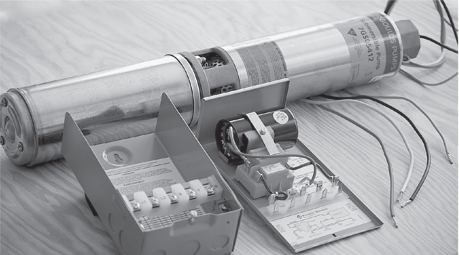
FIGURE 10-10 Submersible pump and control box with cover removed.
Some people worry that a submersible pump or the wire that supplies it will short out because it is under water. This actually never happens. The pump motor is hermetically sealed, the windings encapsulated in epoxy resin. Heat treating converts this epoxy-resin mix into an impermeable solid so that water can never get to the motor. The whole thing is in a sealed stainless steel can. For this reason, it is impossible ever to rebuild this motor. The other side of the coin, however, is that the motor is incredibly durable and can be expected to run for many years.
Even though the motor cannot be serviced or repaired, it is separable from the pump. They are held together by long bolts, and it is not difficult to separate the motor, which has a splined shaft, from the pump. Then you can attempt to turn the shaft to determine whether the motor is seized. The pump can be easily disassembled and rebuilt by installing a new impeller kit. Sometimes the pump becomes sand bound, preventing it from turning, so the complete repair consists of cleaning it and bolting it back to the motor.
If the motor has seized, shorted, or draws excessive current, a new one can be purchased as a replacement, and this is a much less expensive option than obtaining a complete new pump/motor. There are about a dozen major submersible-pump manufacturers. Most of them use Franklin motors and control boxes. This system is user friendly and easy to work on, with excellent documentation from the manufacturer.
There are two types of installations—two-wire and three-wire. [This nomenclature does not include the equipment-grounding conductor, which recent National Electrical Code (NEC) cycles have required to protect the worker in the event that the pump/motor is pulled out of the well and powered up for testing purposes.] If the less costly two-wire option is chosen, the start capacitor and electronics are imbedded in the motor at the bottom of the well. The three-wire installation permits a control box with start capacitor and electronics, as shown in Figure 10-11, to be located in the building for easy access.

FIGURE 10-11 The start capacitor and associated electronics for a submersible pump are contained in the control-box cover, making for a very easy change-out.
In the Franklin control box, these components are contained in the cover, which can be easily pulled off for testing and replacement. Inside the box is a label showing acceptable current and resistance reading, which may be taken at the box or at the wellhead, without pulling the pump/motor. At least 50 percent of the time, a malfunctioning submersible-pump system can be restored simply by replacing the control-box cover.
The output terminals of the control box are wired to the pump motor using pump cable that is color-coded black, red, and yellow (plus a green for the equipment-grounding conductor). Many people believe that the purpose of the three conductors is to provide two hot legs and a neutral for the motor. However, as with most 240-volt motors, the pump motor does not need a neutral.
The red is start, the black is run, and the yellow is common. One of the functions of the control box is to energize the red for a short time to get the motor up to speed, after which the black is switched online. The capacitor is wired into the start circuit. The output lugs at the control box are marked, and the motor has a color-coded pigtail so that you never have a problem knowing how to make the connections.
In the same manner as the suction-pump wiring, the 240-volt supply is brought to the pressure switch, which is a double-pole, in-line device. The load lugs of the pressure switch are wired to the line lugs of the control box. The pump cable begins at the control-box output lugs, labeled “Load.” Here again, this wire should be in flexible metallic conduit FMC to a junction box mounted on the wall. Liquid-tight flexible conduit is also used to good effect. Through a polyvinyl chloride (PVC) or metal LB, as shown in Figure 10-12, or knockout in the back of a 4 × 4 box, the pump cable exits the building and goes underground to the wellhead. For a first-class installation that is Code compliant, the pump cable should nowhere be visible, including at the wellhead.

FIGURE 10-12 Type LB fittings are used to make 90-degree bends in a raceway system. The removable cover facilitates pulling the conductors.
A common Code violation is to put the pump cable in black PVC water pipe of the type that is used for underground waterlines. This piece will be seen where it comes out of the ground and attaches to the wellhead, perhaps by means of a hose clamp. If you want to show the world that you know what you are doing, use the gray Underwriters Laboratories (UL)–listed sunlight-resistant PVC conduit with a threaded adapter.
If you are going to pull the pump, remove the cover from the control box. This disconnects the power. Also, lock out the disconnect and shut off the breaker at the entrance panel. At the wellhead, remove the well cap and disconnect the electrical wires.
A T-handle tool is necessary to remove the pump, but no digging is required. To make the T-handle tool, use black or galvanized 1-inch steel water pipe. You need a piece of pipe, threaded at both ends, that is long enough to reach the pitless adapter, a tee, and two lengths about 8 inches long for handles.
Use a very strong flashlight or trouble light to locate the pitless adapter. It usually will be at the side of the well facing the building, lining up with the burial trench. In cold areas where the frost goes deep, it should be about 5 feet below grade.
Place the threaded end of the T-handle tool into the well casing, threaded end first. Very gently probe around until you contact the pitless adapter. This is a heavy brass fitting that has to be seen to be appreciated.
Screw the T-handle tool into the pitless adapter by turning it clockwise until several threads are engaged. Then, with a sharp upward motion, lift the T-handle so that the inner part of the pitless adapter separates from the outer part, which goes through a hole in the well casing and is attached to the buried water line. The inner part of the pitless adapter is attached to the pipe that goes to the bottom of the well, to which the pump/motor is attached, typically suspended about 8 feet up.
If the drop pipe is steel, a crane will be needed to pull it. If the line is PVC and no longer than 300 feet, it can be pulled by hand, with one or two helpers. Usually the electrical line is taped and/or cable tied to the drop pipe at 5-foot intervals. When pulling the pump, it is essential that the pipe and cable go straight up and out of the well casing without dragging across the sharp steel edge. Any nick in the wire insulation can cause the conductor to ground out, resulting in fast cycling at the control box or worse.
A very frequent cause of submersible-pump-system failure is the chafing of a wire under the well cap. If you leave a moderate-sized loop and tape it lightly, this will not happen. It is in this area that the wires are spliced by means of wire nuts. If they are filled with silicone with the openings pointing down, moisture caused by condensation will not cause the electrical joints to corrode.
The submersible pump for residential use is designed to go in a 6-inch well casing in a drilled well, but it is also suitable for installation in concrete well tiles used in a dug well. But you can’t just lay it in at an angle resting on the gravel bottom. To prevent twisting and thrashing about due to reverse torque, the pump/motor must hang suspended a few inches off the bottom. The bearings are designed for vertical operation only, and if the pump/motor sits at an angle, it will have a shortened life.
In constructing a dug well that is going to contain a submersible pump, place the perforated tile through which the waterline is going to enter so that the perforation is at a 45-degree angle to the trench. Using a conduit bender, make an appropriate bend in a piece of 1-inch galvanized steel pipe. This bend will be buried in the ground outside the well tile, and the purpose is so that the pipe cannot turn in the ground, which would allow the drop pipe and pump/motor to move out of plumb.
This steel pipe should terminate near the center of the well, with a 90-degree elbow or tee with a plug attached and pointing down. A vertical-drop pipe should be attached to the elbow and threaded into the pump. The length of this pipe should be such that the pump is suspended a few inches above the bottom surface.
In the horizontal steel pipe, a union should be placed so that the pump can be removed if needed. Bring the electrical line in a PVC sleeve through a separate perforation. Cable-tie it as needed to the water pipe, and leave a loop of slack for a well-organized installation.