
Chapter 7 Security
7.1 Introduction
Providing security is one of the key aspects of mobile networks. One of the more obvious reasons is that the wireless communication can easily be intercepted by anyone within a certain range of the transmitter. There is thus a risk that the data that is transferred is eavesdropped, or even manipulated, by third parties. There are also other threats, for example, an attacker may trace a user’s movement between radio cells in the network or discover the whereabouts of a specific user. This may constitute a significant threat to users’ privacy. Apart from security aspects directly related to the end-users, there are also security aspects related to the network operator and the service providers as well as security between network operators in roaming scenarios. For instance, there should be no doubt regarding which user and roaming partner were involved in generating certain traffic in order to assure a correct and fair charging of the subscribers.
There are also regulatory requirements related to security and these may differ between countries and regions. The regulations can, for example, be related to exceptional situations where law enforcement agencies can request information about the activities of a terminal as well as intercept the telecommunications traffic. The framework in a telecommunications system for supporting this is called ‘lawful intercept’ and is described in a separate chapter. There may also be regulations to ensure that end-users’ privacy is protected when using mobile networks. Requirements like these are in general captured in the national and/or regional laws and regulations by the responsible authorities for that specific nation/region.
Below we discuss different aspects of security in mobile networks, starting with a brief discussion on key security concepts and security domains. Then security aspects related to both end-users as well as within and between network entities are discussed.
7.2 Security Services
7.2.1 Introduction
Before we go into the actual security mechanisms of EPS, it may be useful to briefly go through some basic security concepts which are important in cellular networks.
Before a user is granted access to a network, authentication in general has to be performed. During authentication the user proves that he or she is the one he/she claims to be. Typically, mutual authentication is desired, where the network authenticates the UE and the UE authenticates the network. Authentication is in general done with a procedure where each party proves that it has access to a secret known only to the participating parties, for example, a password or a secret key.
The network also verifies that the subscriber is authorized to access the requested service, for example, to get access to EPS using a particular access network. This means that the user must have the right privileges (i.e. a subscription) for the type of services that is requested. Authorization for an access is often done at the same time as authentication. It can be noted that different kinds of authorization may be done in different parts of the network and at different instances during an IP session. The network may, for example, authorize the use of a certain access technology, a certain QoS profile, a certain bit rate, access to certain services, etc.
Once the user has been granted access, there is a desire to protect the signalling traffic and user plane traffic between the UE and the network and between different entities within the network. Ciphering and/or integrity protection may be applied for this purpose. With ciphering (i.e. encryption and decryption) we ensure that the information transmitted is only readable to the intended recipients. To accomplish this, the traffic is scrambled so that it becomes unreadable for anyone who manages to intercept it, except for the entities that have access to the correct cryptographic keys. Integrity protection on the other hand is a means to detect whether traffic that reaches the intended recipient has not been modified, for example, by an attacker between the sender and the receiver. If the traffic has been modified, the integrity protection ensures that the receiver is able to detect it. Ciphering and integrity protection serves different purposes and the need for ciphering and/or integrity protection differs depending on what traffic it is. Furthermore, the data protection may be done on different layers in the protocol stack and as we will see, EPS supports data protection features on both layers 2 and 3 depending on scenario.
In order to encrypt/decrypt as well as to perform integrity protection, the sending and receiving entities need cryptographic keys. It may seem tempting to use the same key for all purposes, including authentication, ciphering, integrity protection, etc. However, using the same key for several purposes should in general be avoided. One reason is that in case an attacker manages to recover the key by breaking, for example, the encryption algorithm, the attacker would at the same time learn the key used also for authentication and integrity protection. Furthermore, the keys used in one access should not be the same as the keys used in another access. If they would be the same, the keys recovered by an attacker in one access with weak security features, could be reused also to break accesses with stronger security features. The weakness of one algorithm or access thus spreads to other procedures or accesses. To avoid this, keys used for different purposes and in different accesses should be distinct, and an attacker who manages to recover one of the keys, shall not be able to learn anything useful about the other keys. This property is called key separation and, as we will see, this is an important aspect of EPS security design. In order to achieve key separation, the UE and the EPC derives distinct keys during the authentication process that are used for different purposes.
By privacy protection we here mean the features that are available to ensure that information about a subscriber does not become available to others. For example, it may include mechanisms to ensure that the permanent user ID is not sent in clear text over the air link. If done, it would mean that an eavesdropper could detect the movements and travel patterns of a certain user.
Laws and directives of individual nations and regional institutions (e.g. European Union), typically define a need to intercept telecommunications traffic and related information. This is referred to as lawful intercept and may be used by law enforcement agencies in accordance with the laws and regulations.
7.2.2 Security domains
In order to describe the different security features of EPS it is useful to divide the complete security architecture into different security domains. Each domain may have its own set of security threats and security solutions. The 3GPP TS 33.401 divides the security architecture into different groups or domains:
-
Network access security
-
Network domain security
-
User domain security
-
Application domain security
-
Visibility and configurability of security.
The first group is specific to each access technology (e.g. E-UTRAN, GERAN, UTRAN, etc), whereas the others are common for all accesses. Figure 7.2.2.1 provides a schematic illustration of different security domains.
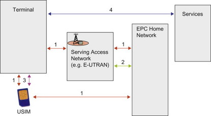
Figure 7.2.2.1 Schematic figure of different security domains.
1. Network access security
By network access security we mean the security features that provide a user with a secure access to the EPS. This includes mutual authentication as well as privacy features. In addition, protection of signalling traffic and user plane traffic in the particular access is also included. This protection may provide confidentiality and/or integrity protection of the traffic. Network access security is in general access specific, that is, the detailed solutions, algorithms, etc differ between accesses. Further details for different types of accesses are provided later in this chapter.
2. Network domain security
Mobile networks contain many network entities and reference points between these entities. The network domain security refers to the features that allow these network nodes to securely exchange data and protect against attacks on the network between the nodes.
3. User domain security
User domain security refers to the set of security features that secure the access to terminals. This can for example, be that the user needs to enter a PIN code before being able to access the terminal.
4. Application domain security
With application domain security is meant the security features used by applications such as HTTP (for web access) or IMS.
Application domain security is in general end-to-end between the application in the terminal and the peer entity providing the service. This is in contrast to the previous security features listed which provide hop by hop security, that is, they apply to a single link in the network only. If each link (and node) in the chain that requires security is protected, the whole end-to-end chain can be considered secure.
Since application level security traverses on top of the user plane transport provided by EPS, and as such is more or less transparent to EPS, it will not be discussed further in this book. For more information on IMS security, see for example, Camarillo and Garcia-Martin (2008).
5. Visibility and configurability of security
This is the set of features that allows the user to learn whether a security feature is in operation or not and whether the use and provision of services should depend on the security feature. In most cases the security features are transparent to the user and the user is unaware that they are in operation. For some security features the user should however be informed about the operational status. For example, usage of encryption in E-UTRAN depends on operator configuration and it should be possible for the user to know whether it is used or not, for example, by a symbol on the terminal display. Configurability is the property that the user can configure whether the use or the provision of a service should depend on whether a security feature is in operation.
7.3 Network Access Security
7.3.1 Introduction
As mentioned previously, network access security is in many aspects specific to each access. Below we go into some details on access security in different types of accesses such as E-UTRAN, HRPD and a WLAN hotspot. These three examples represent well the different possibilities to get access to the EPS. We also describe additional aspects for the case DSMIPv6 is used.
Common in all cases is the use of USIM.
7.3.2 Access security in E-UTRAN
It was clear from the start of the standardization process that E-UTRAN should provide a security level, at least as high as that of UTRAN. Access security in E-UTRAN therefore consists of different components, similar to those that can be found in UTRAN:
-
Mutual authentication between UE and network.
-
Key derivation to establish the keys for ciphering and integrity protection.
-
Ciphering, integrity and replay protection of NAS signalling between UE and MME.
-
Ciphering, integrity and replay protection of RRC signalling between UE and eNB.
-
Ciphering of the user plane. The user plane is ciphered between UE and eNB.
-
Use of temporary identities in order to avoid sending the permanent user identity (IMSI) over the radio link.
Figure 7.3.2.1 illustrates some of these components in the network.
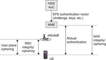
Figure 7.3.2.1 Security features for E-UTRAN.
Below we will discuss in detail how each of these components has been solved.
The authentication procedure in E-UTRAN is in many ways similar to the authentication procedure in GERAN and UTRAN but there are also differences. To understand the reason behind the differences, it is useful to first briefly look at the security features for GERAN and UTRAN systems. As with all security features in communication systems, what was considered sufficiently secure at one point in time may turn out not to be sufficient a few years later when attack methods and computing power have developed further. This is also true for 3GPP radio accesses. When GERAN was developed, some limitations were deliberately accepted. For example, mutual authentication is not performed in GERAN where it is only the network that authenticates the terminal. It was thought that there was no need for the UE to authenticate the network, since it was unlikely that anyone would be able to set up a rogue GERAN network. When UTRAN/UMTS was developed, enhancements were made to avoid some of the limitations of GERAN. For example, mutual authentication was introduced. These new security procedures are one reason why a new type of SIM card was needed for UMTS; the so called UMTS SIM (or USIM for short). With the introduction of E-UTRAN, further improvement is taking place. One important aspect is, however, that it has been agreed that the use of USIM in the terminal shall be sufficient to access E-UTRAN, that is, no new type of SIM card shall be needed. The new features are instead supported by software in the terminal and the network.
Mutual authentication in E-UTRAN is based on the fact that both the USIM card and the network have access to the same secret key K. This is a permanent key that is stored on the USIM and in the HSS/AuC in the home operator’s network. Once configured, the key K never leaves the USIM or the HSS/AuC. The key K is thus not used directly to protect any traffic and it is also not visible to the end-user. During the authentication procedure, other keys are generated from the key K in the terminal and in the network that are used for ciphering and integrity protection of user plane and control plane traffic. For example, one of the derived keys is used to protect the user plane, while another key is used to protect the NAS signalling. One reason why several keys are produced like this is to provide key separation and to protect the underlying shared secret K. In UTRAN and GERAN, the same keys are used for control signalling and user traffic, and hence this is also an enhancement compared to these earlier standards. This is, however, not the only key management enhancement as will be discussed below.
The mechanism for authentication as well as key generation in E-UTRAN is called EPS Authentication and Key Agreement (EPS AKA). Mutual authentication with EPS AKA is done in the same manner as for UMTS AKA, but as we will see when we go through the procedure, there are a few differences when it comes to key derivation.
EPS AKA is performed when the user attaches to EPS via E-UTRAN access. Once the MME knows the user’s IMSI, the MME can request an EPS authentication vector (AV) from the HSS/AuC as shown in Figure 7.3.2.2. Based on the IMSI, the HSS/AuC looks up the key K and a sequence number (SQN) associated with that IMSI. The AuC steps (i.e. increases) the SQN and generates a random challenge (RAND). Taking these parameters and the master key K as input to cryptographic functions, the HSS/AuC generates the UMTS AV. This AV consists of five parameters: an expected result (XRES), a network authentication token (AUTN), two keys (CK and IK), as well as the RAND. This is illustrated in Figure 7.3.2.3. Readers familiar with UMTS will recognize this Authentication Vector as the parameters that the HSS/AuC would send to the SGSN for access authentication in UTRAN. For E-UTRAN, however, the CK and IK are not sent to the MME. Instead the HSS/AuC generates a new key, KASME, based on the CK and IK and other parameters such as the serving network identity (SN ID). The SN ID includes the Mobile Country Code (MCC) and Mobile Network Code (MNC) of the serving network. A reason for including SN ID is to provide a better key separation between different serving networks to ensure that a key derived for one serving network cannot be (mis-) used in a different serving network. Key separation is illustrated in Figure 7.3.2.3.
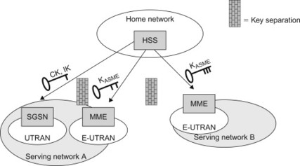
Figure 7.3.2.3 Key separation between 3GPP accesses and serving networks.
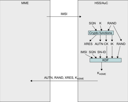
Figure 7.3.2.2 MME fetching the EPS Authentication Vector from HSS/AuC.
The KASME together with XRES, AUTN and RAND constitutes the EPS AV that is sent to MME. The CK and IK never leave the HSS/AuC when E-UTRAN is used. In order to distinguish the different AVs, the AUTN contains a special bit called the ‘separation bit’ indicating whether the AV shall be used for E-UTRAN or for UTRAN/GERAN. A reason for going through this extra step with the new key KASME, instead of using CK and IK for ciphering and integrity protection like in UTRAN, is to provide a strong key separation towards legacy GERAN/UTRAN systems. For more details on the generation of the EPS AV, please see 3GPP TS 33.401, [33.401].
Mutual authentication in E-UTRAN is performed using the parameters RAND, AUTN and XRES. The MME keeps the KASME and XRES but forwards RAND and AUTN to the terminal shown in Figure 7.3.2.4. Both RAND and AUTN are sent to the USIM. AUTN is a parameter calculated by the HSS/AuC based on the secret key K and the SQN. The USIM now calculates its own version of AUTN using its own key K and SQN and compares it with the AUTN received from the MME. If they are consistent, the USIM has authenticated the network. Then the USIM calculates a response RES using cryptographic functions with the key K and the challenge RAND as input parameters. The USIM also computes CK and IK in the same way as when UTRAN is used (it is after all a regular UMTS SIM card). When the terminal receives RES, CK and IK from the USIM, it sends the RES back to the MME. The MME authenticates the terminal by verifying that the RES is equal to XRES. This completes the mutual authentication. The UE then uses the CK and IK to compute KASME in the same way as HSS/AuC did. If everything has worked out, the UE and network has authenticated each other and both UE and MME now have the same key KASME. (Note that none of the keys K, CK, IK or KASME was ever sent between UE and network.)
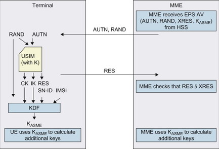
Figure 7.3.2.4 EPS AKA between UE and MME.
Now all that remains is to calculate the keys to be used for protecting traffic. As mentioned above, the following type of traffic is protected between UE and E-UTRAN:
-
NAS signalling between UE and MME
-
RRC signalling between UE and eNB
-
User plane traffic between UE and eNB.
Different keys are used for each set of procedures above, and also different encryption and integrity protection keys are used. The key KASME is used by UE and MME to derive the keys for encryption and integrity protection of NAS signalling (KNASenc and KNASint). In addition, the MME also derives a key that is sent to the eNB (the KeNB). This key is used by the eNB to derive keys for encryption of the user plane (KUPenc) as well as encryption and integrity protection of the RRC signalling between UE and eNB (KRRCenc and KRRCint). The UE derives the same keys as eNB. The ‘family tree’ of keys is typically referred to as a key hierarchy. The key hierarchy of E-UTRAN in EPS is illustrated in Figure 7.3.2.5.
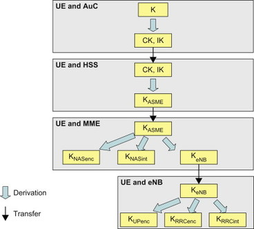
Figure 7.3.2.5 Key hierarchy for E-UTRAN.
Once the keys have been established in the UE and the network it is possible to start ciphering and integrity protection of the signalling and user data. The standard allows use of different cryptographic algorithms for this and the UE and the NW need to agree on which algorithm to use for a particular connection. For more details on which ciphering and integrity algorithms are supported with E-UTRAN, please see 3GPP TS 33.401 [, 33.401].
The final aspect that should be mentioned is the identity protection. In order to protect the permanent subscriber identity (i.e. IMSI) from being exposed in clear text over the radio interface, temporary identities are used whenever possible in a similar way to what is done in UTRAN. Please see the identities section in Chapter 6 for a description on how temporary identities are used in E-UTRAN.
A main enhancement in E-UTRAN as compared to UTRAN is, as was discussed above, the strong key separation between networks and key-usage. A few other enhancements are also worth brief mentioning:
-
Larger key sizes. E-UTRAN supports not only 128-bit keys but can (in future deployments) also use 256-bit keys.
-
Additional protection against compromised base stations. Due to the flattened architecture in E-UTRAN, additional measures were added to protect against a potentially compromised ‘malicious’ radio base station. One of the most important features is the added forward/backward security: each time the UE changes its point of attachment (due to mobility), or, when the UE changes from IDLE to ACTIVE, the air interface keys are updated according to a sophisticated procedure. This means that even in the unlikely event that the keys used so far have been compromised, security can be restored.
7.3.3 Interworking with GERAN/UTRAN
In this book we will not describe the security features applicable to GERAN and UTRAN in any detail. The interested reader is instead referred to books dedicated to GERAN and UTRAN. However, the interworking between GERAN/UTRAN and E-UTRAN will be discussed below.
When a UE moves between GERAN/UTRAN and E-UTRAN, there are different possibilities in order to establish the security context to be used in the target access. One possibility would be to perform a new authentication and key agreement procedure every time the UE enters a new access. In order to reduce the delays during handover between GERAN/UTRAN and E-UTRAN, however, this may not be desirable. Instead, handovers can be based on native (or cached) or mapped security contexts. If the UE has previously been active in E-UTRAN access, then moved to GERAN/UTRAN and later returns to E-UTRAN, the UE and NW may have cached a native security context for E-UTRAN, including a native KASME, from the previous time the UE was in E-UTRAN. In this way a full AKA procedure in the target access is not needed during the inter-RAT handover. If a native context is not available, it is instead possible to map the security context used in the source access to a security context for the target access. This security context mapping is supported when moving between different 3GPP accesses. When mapping is performed, the UE and MME derive keys applicable to the target access (e.g. KASME for E-UTRAN) based on the keys used in the source access (e.g. CK, IK for UTRAN). The mapping is based on a cryptographic function, f, having the property that it protects the source context from the mapped target context. This assures that a mapped context cannot ‘backwards’ compromise the context from which it was mapped. An example of such a mapping is illustrated in Figure 7.3.3.1.
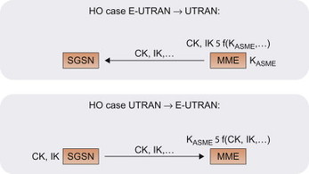
Figure 7.3.3.1 Examples of mapping security context in handover between E-UTRAN and UTRAN.
There are, however, a few important aspects related to such a mapping of security context since the protection is only one-way. If the source context has already been compromised, then the mapped context will inherit this property. Also, as we have already mentioned above, the level of security is not the same in all accesses. This is where key separation becomes important. Unless the different accesses are kept separated from a security point of view, the vulnerability of one access may spread into other accesses not susceptible to the same vulnerabilities. Therefore, in case a security context from for example, GERAN has been mapped to a security context for E-UTRAN, it is highly recommended that a full AKA run is performed as soon as possible after entering E-UTRAN to establish a fresh, native, E-UTRAN security context.
7.3.4 Access security in trusted non-3GPP accesses
One example of a cellular technology not specified by 3GPP, but that can be used to provide access to EPC, is evolved HRPD (eHRPD). The security features of HRPD that are specified by 3GPP2 are thus not under the control of 3GPP. Still, HRPD has the capabilities to provide a strong access control, mutual authentication as well as protection of signalling and user plane traffic sent over the HRPD radio link. Even though not specified by 3GPP, it is reasonable that these security features are sufficient for providing access to EPS. Typically, HRPD would be connected directly to EPC using the S2a or S2c reference points.
Access authentication in eHRPD is based on EAP-AKA; or, to be more precise, 3GPP has agreed to use a revision of EAP-AKA called EAP-AKA', but more about this below. On a high level, EAP-AKA (and EAP-AKA') is a method to perform AKA-based authentication over an access even if there is not native support for AKA in that particular access. This makes it possible to perform 3GPP-based access authentication using the same credentials – the shared secret key K located in USIM and HSS/AuC– as for 3GPP accesses. EAP-AKA runs between the UE and the 3GPP AAA Server, (Figure 7.3.4.1). In order to perform the AKA-based authentication, the 3GPP AAA Server downloads the Authentication Vector from HSS/AuC. For more details on EAP, please see the EAP protocol section in Chapter 11.
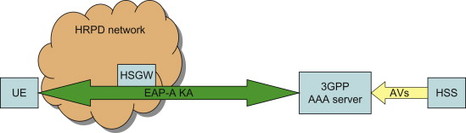
Figure 7.3.4.1 EAP-AKA based access authentication for eHRPD.
It should, however, be noted that the key hierarchy and details regarding key derivation differ somewhat between EPS AKA and EAP-AKA. With EAP-AKA, the Authentication Vector from HSS/AuC is a starting point for the authentication procedure, just like in EPS AKA. Then, a Master Key is derived by the UE and 3GPP AAA Server based on the CK and IK; in a way this is conceptually similar to how KASME is derived from CK and IK with EPS AKA. This Master Key is used to derive further keys, for example, keys that are used to protect user plane and control plane traffic in the eHRPD access. In this book we will not go into further details regarding security in the eHRPD access.
As already mentioned above, a revision of EAP-AKA called EAP-AKA' is used for access authentication in eHRPD and other trusted non-3GPP accesses. EAP-AKA is defined in RFC 4187, [4187] and EAP-AKA’ in RFC 5448, [5448]. The revisions made in EAP-AKA’ is that the procedure has been more aligned with EPS AKA. In practice this means that the serving network name is taken into account in the key derivation schemes. This even further strengthens the key separation as the keys used in one serving network cannot be used in another serving network.
There is no security context mapping when moving between 3GPP and eHRPD, or between 3GPP and non-3GPP access in general. However, despite the lack of context mapping, the optimized eHRPD interworking, described in the mobility section of Chapter 6 allows for optimizations of the security procedures during handover between E-UTRAN and eHRPD. When a UE is active in E-UTRAN access and the dedicated signalling connection with eHRPD (via S101) is setup, the UE can perform the EAP-AKA’ procedure for eHRPD before actually handing over to eHRDP access. Once the handover takes place, the security context is already established in the target eHRPD access. Also in the other direction, that is, handover from eHRPD to E-UTRAN, the EPS AKA security procedures for E-UTRAN can be performed via the S101 signalling connection.
For privacy protection, EAP-AKA supports means to use temporary identities (so called pseudonyms) in a similar way as for E-UTRAN access. The EAP-AKA pseudonyms are, however, of a different format than the temporary identities used in 3GPP accesses.
7.3.5 Access security in untrusted non-3GPP access
Another example of an access that can be used to provide connectivity to EPS is WLAN. WLAN can be used in many scenarios, for example, in corporate environments, in the home or in public places such as airports and coffee shops. The level of security provided by a WLAN access also differs between deployments. For home and corporate use, WLAN security solutions such as WEP and WPA are often used. In public places it is, however, more common to turn WLAN security off completely. Instead access control is provided by the means of a web page where the user can enter a username and a password. The user may for example, have received a username and password for a temporary subscription at the same time he or she bought a cup of coffee. Once the user has entered the credentials on the web page, Internet access is provided. The WLAN access does in this case not provide any encryption or integrity protection of the user plane and is vulnerable to many types of attacks. In such deployments, WLAN access to EPS will therefore most likely be handled as an un-trusted non-3GPP access. In other deployments with WLAN security turned on, WLAN might be treated as a trusted access.
Now the user wants to get access to the services provided by his or her operator via EPS. In general the coffee shop where the end-user is located and wants to connect does not have any agreement to connect to the EPC directly. Equally important, since no or very limited security is provided, providing direct access to EPC would make EPC vulnerable to attacks. The solution to this problem, as defined by EPS, is to set up an IPSec tunnel between the UE and a so called ePDG inside the operator’s network when the access is un-trusted (Figure 7.3.5.1). The ePDG acts as a secure entry point into the EPC.
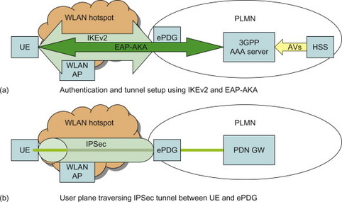
Figure 7.3.5.1 (a) Authentication using IKEv2 and EAP-AKA between UE and ePDG. (b) User plane traffic is protected in IPSec tunnel between UE and ePDG.
In order to setup the IPSec tunnel, the UE must first perform mutual authentication towards the ePDG and operator network, as well as establish keys for the IPSec security association. This is done using the IKEv2 protocol. Once the UE has connected to the WLAN and discovered the IP address of the ePDG (can be done using DNS) it starts the IKEv2 procedure. As part of IKEv2, public key-based authentication with certificates is used to authenticate the ePDG. The UE is on the other hand authenticated in a similar manner as for E-UTRAN, that is, based on the credentials on the USIM. Within IKEv2, EAP-AKA is run to perform the AKA-based authentication and key agreement. Therefore, the USIM-based authentication described in the previous sections can be performed also when the UE accesses over a generic WLAN hotspot. EAP-AKA is the same protocol as was described in Section 7.3.4. The difference is that now EAP-AKA is run as part of the IKEv2 procedure, while in Section 7.3.4 EAP-AKA’ is run as part of the attach procedure in a trusted non-3GPP access such as eHRPD. Similar properties regarding key generation and privacy protections as mentioned about EAP-AKA’ in Section 7.3.4 apply to the EAP-AKA in this scenario as well.
It should be noted that the WLAN hot spot has been used in this section as an example scenario where connection using IKEv2 and IPSec towards an ePDG is suitable. The ePDG may also be used for any access that can provide IP connectivity, for example, from the DSL connection at home, independent of security properties of the underlying access.
7.3.6 Special considerations for host-based mobility DSMIPv6
In the previous sections we have described the security features for two main scenarios, a user attaching to an access network that provides a high level of security, for example, E-UTRAN and eHRDP, and a user attaching to an access network where additional security protection is needed (IPSec tunnel over an unprotected WLAN access).
However, also the choice of mobility protocol has impact on the security features. As has been described in earlier chapters, specifically the mobility section of Chapter 6 there are two main methods for providing access in EPS, either using network-based mobility (GTP or PMIP) or host-based mobility (DSMIPv6 or MIPv4). When network-based mobility is used, the access security described in the previous chapters provides the needed security between UE and the EPC. However, when host-based mobility is used, there is a need to provide security also for the host-based mobility protocol between UE and PDN GW.
When DSMIPv6 is used, the DSMIPv6 signalling between UE and PDN GW is integrity protected using IPSec. In order to establish the IPSec security association for the DSMIPv6 signalling, the user is first authenticated using IKEv2 and EAP-AKA, as illustrated in Figure 7.3.6.1. This EAP-AKA based authentication for DSMIPv6, as well as IPSec protection of the DSMIPv6 signalling, is done in addition to any access level authentication and user plane protection that may be performed (as described in previous chapters). This means that the DSMIPv6 signalling may be protected twice, first using the general user plane protection on access level and then using IPSec between UE and PDN GW. Additionally, in case there is an ePDG on the path, there is an IPSec tunnel between UE and ePDG.
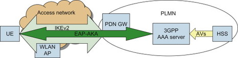
Figure 7.3.6.1 IKEv2 and EAP-AKA based authentication and key agreement for DSMIPv6.
On a high level, the basic security features for MIPv4 are similar to those of DSMIPv6, that is, the MIPv4 signalling needs to be integrity protected to ensure that only authenticated UEs can send MIPv4 signalling messages to the PDN GW. However, the details of the security solution for MIPv4 are quite different compared to DSMIPv6. MIPv4 performs integrity protection of signalling using a special authentication element in the signalling messages. The messages are thus not protected using IPSec between UE and the network. For more details on the MIPv4 security solution, please see 3GPP TS 33.402, [33.402].
7.4 Network Domain Security
When GSM/GERAN was developed, no solution was specified for how to protect the traffic in the core network. This was perceived not to be a problem, since the GSM networks typically were controlled by a small number of large institutions. Furthermore, the original GSM networks were only running circuit-switched traffic. These networks used protocols and interfaces specific for circuit switched voice traffic and typically only accessible to large telecom operators. With the introduction of GPRS as well as IP transport in general, the signalling and user plane transport in 3GPP networks now runs over networks and protocols that are more open and accessible to others than the major institutions in the telecom community. This brings a need to provide enhanced protection also to traffic running over core network interfaces. For example, the core network interfaces may traverse third-party IP transport networks, or the interfaces may cross operator boundaries like in roaming cases. 3GPP has therefore developed specifications for how IP-based traffic is to be secured also in the core network and/or between a core network and some other (core) network. On the other hand, it can be noted that also today, if the core network interfaces run over trusted networks, for example, a transport network owned by the operator that is physically protected, there would be little need for this additional protection.
The specifications for how to protect the IP-based control plane traffic is called Network Domain Security for IP-based control planes (NDS/IP) and are available in 3GPP TS 33.210, [33.210]. This specification introduces the concept of security domains. The security domains are networks that are managed by a single administrative authority. Hence, the level of security and the available security services are expected to be the same within a security domain. An example of a security domain could be the network of a single telecom operator, but it is also possible that a single operator divides its network into multiple security domains. On the border of the security domains, the network operator places Security Gateways (SEGs) to protect the control plane traffic that passes in and out of the domain. All NDS/IP traffic from network entities of one security domain is routed via a SEG before exiting that domain towards another security domain. The traffic between the SEGs is protected using IPSec, or to be more precise, using IPSec Encapsulated Security Payload (ESP) in tunnel mode. The Internet Key Exchange (IKE) protocol, either IKEv1 or IKEv2, is used between the SEGs to set up the IPSec security associations. An example scenario is illustrated in Figure 7.4.1.
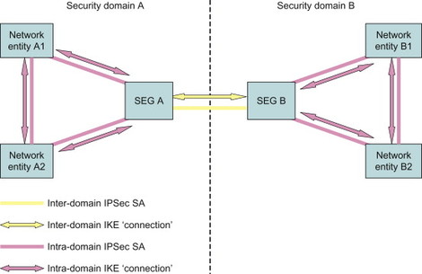
Figure 7.4.1 Example of two security domains employing NDS/IP.
A case of special relevance to EPS and E-UTRAN is the S1-U interface between EPC and the E-UTRAN. This interface needs to be properly protected (physically and/or by NDS/IP) since the user plane data protection would otherwise be terminated in the eNodeB, potentially exposing sensitive data on S1.
Also within a security domain, that is, between different network entities or between a network entity and a SEG, the operator may choose to protect the traffic using IPSec. The end-to-end path between two network entities in two security domains is thus protected in a hop-by-hop fashion.
Although NDS/IP was initially intended mainly for the protection of control plane signalling only, it is possible to use similar mechanisms to protect the user plane traffic. Indeed, for the aforementioned case of user data over S1, NDS/IP will be used in deployments that require it.
7.5 User Domain Security
The most common security feature in this user domain context is the secure access to the USIM. Access to the USIM shall be blocked until the USIM has authenticated the user. Authentication is in this case based on a shared secret (the PIN code) that is stored inside the USIM. When the user enters the PIN code on the terminal, it is passed on to the USIM. If the user provided the right PIN code, the USIM allows access from the terminal/user, for example, to perform the AKA-based access authentication.
7.6 Lawful Intercept
Lawful Interception (LI) is one of the regulatory requirements operators must satisfy as legal obligation toward the Law Enforcement Agencies (LEA) and Government Authorities in most countries they are operating their businesses in. Within 3GPP standards, this is currently defined as: Laws of individual nations and regional institutions (e.g. European Union), and sometimes licensing and operating conditions define a need to intercept telecommunications traffic and related information in modern telecommunications systems. It has to be noted that lawful interception shall always be done in accordance with the applicable national or regional laws and technical regulations (as per 3GPP TS 33.106 “Lawful Interception Requirements”, [33.106]). LI allows appropriate authorities to perform interception of communication traffic for specific user(s) and this includes activation (requires legal document such as a warrant), deactivation, interrogation as well as invocation procedures. A single user (i.e. interception subject) may be involved where interception is being performed by different LEAs. In such scenarios, it must be possible to maintain strict separation of these interception measures. The Intercept Function is only accessible by authorized personnel. As LI has regional jurisdiction, national regulations may define specific requirements on how to handle the user’s location and interception across boundaries. As a necessary part of the mobile communications systems, handover is a basic process in EPS. Interception is also carried out when handover has taken place, when required by national regulations.
This subsection deals with this aspect on a brief and high level in order to complete the overall EPS functionalities; it is intended as a description of the 3GPP LI standards and not of any function implemented in the Ericsson or other vendors’ nodes. The Legal Intercept function in itself does not put requirements on how a system should be built but rather requires that provisions be made for legal authorities to be able to get the necessary information from the networks via legal means, according to specific security requirements, without disruption of the normal mode of operations and without jeopardizing the privacy of communications not to be intercepted. Note that LI functions must operate without being detected by the person(s) whose information is being intercepted and other unauthorized person(s). As this is the standard practice for any communications networks already operating today around the world, EPS is no exception.
The process of collection of information is done by means of adding specific functions into the network entities where certain trigger conditions will then cause these network elements to send data in a secure manner to a specific network entity responsible for such role. Moreover, specific entities provide administration and delivery of intercepted data to Law Enforcement in the required format. As an example, Figure 7.6.1 shows the LI architecture for some of the EPS nodes:
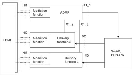
Figure 7.6.1 High-level EPS-LI architecture for S-GW/PDN-GW.
Intercept-related information (also referred to as Events) are triggered by activities detected at the network element. Some events applicable to the MME are:
-
Attach
-
Detach
-
Tracking Area Update
-
UE requested PDN connectivity
-
UE requested PDN disconnection.
Events are triggered in case of E-UTRAN access at the following user plane-related activities detected at the Serving GW and at the PDN GW:
-
Bearer activation (valid for both Default and Dedicated bearer)
-
Bearer Modification
-
Bearer Deactivation
-
Start of Intercept with bearer active
-
UE requested bearer resource modification.
Depending on national regulations, intercept-related information collected may also be reported by the HSS.
Local regulations may allow for the operators to charge for the services rendered towards the Legal Interception requesting party, such as charging data collection process may include some or all of the following situations to be supported:
-
Use of network resources
-
Activation and deactivation of the target
-
Every intercept invocation
-
Flat rate.
This brief overview represents high-level functions supported in EPS in order to fulfil the legal interception requirements. This does not in any way show the complete possibilities or aspects of this function since it is deemed unrelated to the overall architecture aspects of the new system, but rather shown for completeness of the system in itself.