
Chapter 10 EPS network entities and interfaces
In this chapter we will describe in more detail the different network entities, interfaces, protocols and procedures used in EPS. This chapter can be used as a reference for readers wanting to see more details than preceding chapters. Before jumping into the actual descriptions however, it is useful to take a look at what we actual mean by a network entity, an interface, a protocol and a procedure.
A network entity in EPS is what sometimes called a ‘logical entity’. This means that in the 3GPP standard it is a logically separate entity with a well-defined functionality. There are also well-defined interfaces between different network entities. This does not, however, imply that actual physical ‘boxes’ implemented by vendors and deployed in real networks have to correspond one-to-one with the network entities in the standard. Vendors may implement a network entity as a standalone product, or may choose to combine different network entities in the same product. It can for example be beneficial to combine a Serving GW and a PDN GW in the same node in order to reduce the number of physical in order to nodes that the user plane has to traverse in non-roaming cases.
Although 3GPP uses the term reference point to denote an association between two logical network entities we have chosen the more commonly used term interface in this book. There are some differences in the formal definition of a reference point and an interface but for the purpose of this book the difference has no practical implications. Interfaces in 3GPP typically have a prefix letter and one or two additional letters. In GPRS, most interfaces start with the letter ‘G’ while in EPS most interfaces start with the letter ‘S’.
A protocol is defined in TS 29.905 [29.905] as ‘A formal statement of the procedures that are adopted to ensure communication between two or more functions within the same layer of a hierarchy of functions’; this definition is taken from ITU-T, document I.112, [I.112]. This could possibly be described in other words as a well-defined set of rules for sending information between two network entities. These rules typically cover transmission, message and data formatting, error handling, etc. EPS uses protocols defined by the Internet Engineering Task Force (IETF) as well as protocols defined by 3GPP. When IETF protocols are used, such as Diameter or IPSec, 3GPP specifies how these protocols are applied in the 3GPP architecture and what protocol options and amendments shall be used or shall not be used. In some cases new IETF RFCs are created to specify protocol amendments as required by 3GPP.
It is important to note that there is not a one-to-one mapping between protocols and interfaces. The same protocol may be used on multiple interfaces, and the other way around, multiple protocols may be used on a single interface. One obvious example of the latter is of course that different protocols are used on different layers in the protocol stack. Another example is the S5/S8 interface that supports two protocol alternatives, Proxy Mobile IP (PMIP) and GPRS Tunnelling Protocol (GTP), to implement similar functions. It is also possible to use different protocols to implement different functions on an interface. For example, on the S2c interface IKEv2 is used to establish a security association (SA) while DSMIPv6 is used for mobility purposes.
EPS is an ‘all IP’ system where all protocols are transported over IP networks. This is different from the original GPRS standard where some interfaces supports protocols based on for example ATM and Signalling System No 7 (SS7).
Even though there are numerous interfaces in the EPS architecture, the protocols supported over those interfaces can be grouped into a relatively small number of groups. Figure 10.1 illustrates a few of the most significant protocols and interfaces in EPS, grouped by protocol type. It should be noted that in some cases multiple protocols are supported over a given interfaces.
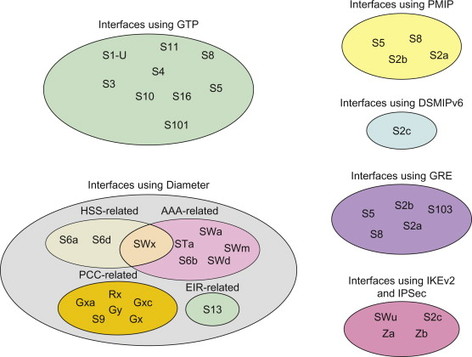
Figure 10.1 Key protocols and interfaces in EPS.
The procedures, that is the message flows, define how commands and messages are transferred between the network entities in order to implement a function (e.g. a handover between two base stations). It may be worth pointing out that the messages and information content shown in the procedures described in Chapter 12 do not necessarily correspond one-to-one with the actual protocol messages. Messages with different names in the message flows may for example be implemented using the same protocol message (or the other way around). Another example is that different logical information elements may be combined into a single parameter when defining the actual protocol fields.
This chapter begins with a brief overview of the EPS network entities. Then the EPS interfaces are described; with an overview of the functions supported and the protocols used over each interface. Chapter 11 describes the protocols aiming to give a basic overview of what protocols are used in EPS and their basic properties. Chapter 12 provides a brief introduction to some of the procedures used in EPS. It should be noted that it is not feasible to make a complete description of all procedures that exist in EPS. Instead we have chosen a few procedures that we think will give a good overview for the intended readers without losing any conceptual information of the key functions supported by EPS. Interested readers may also consult the 3GPP technical specifications 23.060, [23.060], 23.401, [23.401] and 23.402, [23.402] for complete descriptions.
10.1 Network Entities
The network architecture of SAE is comprised of a few different network entities; each network entity has a distinct role in the architecture. This section covers the roles of the different nodes; the eNodeB, the Mobility Management Entity (MME), the Serving GW, the PDN GW and the PCRF.
10.1.1 eNodeB
The eNodeB provides the radio interface and performs radio resource management for Long-Term Evolution (LTE) including radio bearer control, radio admission control and scheduling of uplink and downlink radio resources for individual UEs. The eNodeB also supports IP header compression and encryption of the user plane data. eNodeBs are interconnected to one another via an interface named X2; this interface has several uses, e.g. handover. eNodeBs are also connected to the EPC via the S1 interface, which is split up into the user plane and the control plane. The control plane interface is referred to as S1-MME and terminates in the MME. The S1-U interface, meanwhile, terminates at the Serving GW and handles user plane traffic. The S1 interface supports pooling, that is a many-to-many relation between the eNodeBs and the MMEs and also between the eNodeBs and the Serving GW. The S1 interface also supports network sharing. This allows operators to share the radio network, that is the eNodeBs, while maintaining their own EPC networks.
10.1.2 Mobility management entity
From a Core Network perspective, the MME is the main node for control of the LTE access network. It selects the Serving GW for a UE during the initial attach and also during handover, if necessary, between LTE networks. It is responsible for the tracking and paging procedures for UEs in idle mode and also the activation and de-activation of bearers on behalf of a UE. The MME through interaction with the HSS is responsible for authenticating the end-user. For UEs that are roaming, the MME terminates the S6a interface towards the UEs home HSS. The MME also ensures that the UE has authorization to use (camp on) an Operator’s PLMN and also enforces any roaming restrictions that the UE may have.
In addition, the MME provides control plane functionality for mobility between LTE and 2G/3G access networks. The S3 interface terminates at the MME from the SGSN.
An MME is selected by the MME selection function. Selection is based on network topology, dependent on which MME serves the particular location that a UE is in. If several MMEs serve a particular area, the selection procedure is based on a few different criteria, for example selecting an MME that reduces the need to change it later or perhaps based on load balancing needs. A full description of the MME selection function is covered in, Section 9.2.3.
The MME is also responsible for Non-Access Stratum (NAS) signalling, which terminates at the MME; the MME also acts as the termination point in the network for the security of NAS signalling, handling the ciphering protection and management of security keys.
Lawful Intercept related to signalling also handled by the MME.
10.1.3 Serving GW
The Serving GW performs several functions for both the GTP-based and PMIP-based network architectures. The Serving GW terminates the interface towards E-UTRAN; every UE that attaches to an EPS is associated with a single Serving GW. In the same was as the MME, the Serving GW is selected for the UE based on network topology and UE location. The Domain Name Service (DNS) may be used to resolve a DNS string of possible Serving GW addresses which serve the UE’s location. The selection of Serving GW may be affected by a few criteria; firstly, a Serving GW may be selected based on the fact that its service area may reduce the necessity to change the Serving GW at a later time. Secondly, Serving GW selection may be based on the need for load balancing between different Serving GWs. A full description of the selection procedure is covered in Chapter 9.
Once a UE is associated with a Serving GW, it handles the forwarding of end-user data packets and also acts as a local anchor point when required for inter-eNodeB handover. During handover from LTE to other 3GPP access technologies (inter-RAT handover for other 3GPP access technologies), the Serving GW terminates the S4 interface and provides a connection for the transfer of user traffic from 2G/3G network systems and the PDN GW. During both the inter-NodeB and inter-RAT handovers, the Serving GW sends one or more ‘end-markers’ to the source eNodeB, SGSN, or RNC in order to assist the re-ordering function in the eNodeB.
When a UE is in idle state, the Serving GW will terminate the downlink (DL) path for data. If new packets arrive, the Serving GW triggers paging towards the UE. As part of this, the Serving GW manages and stores information relevant to the UE; for example parameters of the IP bearer service or internal network routing information.
The Serving GW is also responsible for the reproduction of user traffic in the case of lawful intercept.
10.1.4 PDN GW
The PDN GW provides connectivity to external PDNs for the UE, functioning as the entry and exit point for the UE data traffic. A UE may be connected to more than one PDN GW if it needs to access more than one PDN. The PDN GW also allocates an IP address to the UE. These PDN GW functions apply to both the GTP-based and the PMIP-based versions of the SAE architecture. This is covered in more detail in, Section 6.1.
In its role as a gateway, the PDN GW may perform deep packet inspection, or packet filtering on a per-user basis. The PDN GW also performs service level gating control and rate enforcement through rate policing and shaping. From a QoS perspective, the PDN GW also marks the uplink and downlink packets with, for example, the DiffServ Code Point. This is covered in more detail in Section 8.1 and 8.2.
Another key role of the PDN GW is to act as the anchor for mobility between 3GPP and non-3GPP technologies such as WiMAX and 3GPP2 (CDMA/HRPD).
10.1.5 Policy and charging rules function
The Policy and Charging Rules Function (PCRF) is the policy and charging control element of the SAE architecture and encompasses policy control decision and flow-based charging control functionalities. This means that it provides network-based control related to service data flow detection, gating, QoS and flow-based charging towards the Policy and Charging Enforcement Function (PCEF). It should be noted, however, that the PCRF is not responsible for credit management.
The PCRF receives service information from the Application Function (AF) and decides how the data flow for a particular service will be handled by the PCEF. The PCRF also ensure that the user plane traffic mapping and treatment is in accordance with the subscription profile associated with an end-user. The PCRF functions are described in more detail in, Section 8.2.
10.2 Control Plane Between UE, eNodeB and MME
10.2.1 S1-MME
10.2.1.1 General
The E-UTRAN-Uu interface is defined between the UE and the eNodeB and the S1-MME interface is defined between the eNodeB and the MME, as shown in Figure 10.2.1.1.1.
Figure 10.2.1.1.1 S1-MME interface.
10.2.1.2 Interface functionality
The S1-MME interface provides support for functionality such as paging, handover, UE context management, E-RAB management and transparent transport of messages between MME and UE.
10.2.1.3 Protocol
The protocol stack for E-UTRAN-Uu and S1-MME is depicted in Figure 10.2.1.3.1.
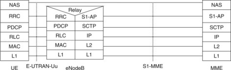
Figure 10.2.1.3.1 Protocol stack for E-UTRAN-Uu and S1-MME.
As can be seen in Figure 10.2.1.3.1, the NAS protocols run directly between the UE and the MME while the eNodeB just acts as a transparent relay. The protocol layers below NAS on E-UTRAN-Uu and S1-MME are called access stratum (AS).
The AS protocols on E-UTRAN-Uu (RRC, PDCP, RLC, MAC and the physical LTE layer) implements the Radio Resource Management and supports the NAS protocols by transporting the NAS messages across the E-UTRAN-Uu interface. Similarly the AS protocols on S1-MME (S1-AP, SCTP, IP, etc.) implements functionality such as paging, handover, UE context management, E-RAB management and transparent transport of messages between MME and eNodeB. The S1-MME interface is defined in 3GPP TS 36.410, [36.410].
The NAS layer consist of an EPS mobility management (EMM) protocol and an EPS session management (ESM) protocol. The EMM protocol provides procedures for the control of mobility and security for the NAS protocols. The ESM protocol provides procedures for the handling of EPS bearer contexts. Together with the bearer control provided by the access stratum, this protocol is used for the control of user plane bearers. The NAS protocols are defined in 3GPP TS 24.301, [24.301].
10.3 GTP-based Interfaces
10.3.1 Control plane
For more detailed procedures and functions of GPTv2-C interfaces can be found in 3GPP technical specification 23.401, [23.401] and 23.060, [23.060].
The detailed messages and parameters for control plane GTPv2-C protocol are defined in 3GPP TS 29.274, [29.274]. At the time of writing, this specification is still under development, thus may not have a complete set of functions. Note that both IPv4 and IPv6 are supported on the transport layer.
The following table shows some messages supported over various interfaces using GTPv2-C.
| Message name | Entity involved | Interfaces |
|
|
|
10.3.2 MME ↔ MME (S10)
The S10 interface is defined between two MMEs and this interface exclusively uses GTPv2-C and for LTE access only. The main function over this protocol is to transfer the contexts for individual terminals attached to the EPC network and thus sent on a per UE basis. This interface is primarily used when MME is relocated. Figure 10.3.2.1 shows the protocol stack for S10 interface.
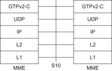
Figure 10.3.2.1 S10 interface.
10.3.3 MME ↔ Serving GW (S11)
The S11 interface is defined between MME and the Serving GW, this interface exclusively uses GTPv2-C and for LTE access only. Due to the separation of the control and user plane functions between MME and Serving GW, the S11 interface is used to create a new session (i.e. to establish the necessary resources for the session) and then manage these sessions (i.e. modify, delete and change) any sessions for a terminal (for each PDN connection) that has established connection within EPS.
The S11 interface is always triggered by some events either directly from the NAS level signalling from the terminal, such as a device attaching to the EPS network, adding new bearers to an existing session or creating a connection towards a new PDN, handover cases, or it may be triggered during network-initiated procedures such as PDN GW-initiated bearer modification procedures. As such the S11 interface keeps the control and user plane procedures in sync for a terminal during the period that the terminal is seen active/attached in the EPS. In case of handover, the S11 interface is used to relocate the Serving GW when appropriate, establish direct or indirect forwarding tunnel for user plane traffic and manage the user data traffic flow.
Figure 10.3.3.1 shows the protocol stack across S11 interface.
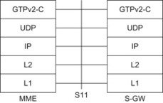
Figure 10.3.3.1 S11 interface.
Note that some of the interactions (e.g. signalling between MME and Serving GW) also need to be performed between Serving GW and PDN GW over S5/S8 interface as described below, though in such case, depending on the protocol choice over S5/S8, the messages are either continued over GTP or transferred over PMIP.
The S11 interface shares common functions with interfaces S4 as well, which can be seen in later parts of this section.
10.3.4 Serving GW ↔ PDN GW (S5/S8)
The S5/S8 interface is defined between the Serving GW and the PDN GW. The S5 interface is used in non-roaming scenarios where the Serving GW is located in the home network, or in roaming scenarios with both Serving GW and PDN GW located in the visited network. The latter scenario is also referred to as Local Breakout. The S8 interface is the roaming variant of S5 and is used in roaming scenarios with the Serving GW in the visited network and the PDN GW in the home network.
When the GTP variant of the protocol is used, the S5/S8 interface provides the functionality associated with creation/deletion/modification/change of bearers for individual user connected to EPS. These functions are performed on a per PDN connection for each terminal. The Serving GW provides the local anchor for all bearers for a single terminal and manages them towards the PDN GW. Figure 10.3.4.1 shows the protocol stack over S5/S8 interface. Section 10.4 contains information on the PMIP variant of S5/S8.
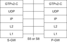
Figure 10.3.4.1 S5 or S8 interface (GTP variant).
10.3.5 SGSN ↔ MME (S3)
The S3 interface is between S4-based SGSN (this SGSN is enhanced to support EPS mobility compared to the Gn/Gp-based SGSN as described in Chapter 3) and MME in order to support handover to/from 2G/3G radio access network for 3GPP accesses. The functions supported include transfer of the information related to the terminal that is being handed over, handover/relocation messages and thus the messages are for individual terminal basis. This interface exclusively supports GTPv2-C and the protocol stack is shown in Figure 10.3.5.1.
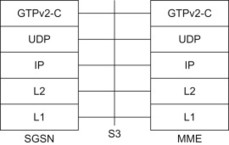
Figure 10.3.5.1 S3 interface.
10.3.6 SGSN ↔ Serving GW (S4)
The S4 interface is between SGSN supporting 2G/3G radio access and Serving GW, it has equivalent functions as the S11 interface but for 2G/3G radio access networks and supports related procedures to support legacy terminals connecting via EPS as well. This interface supports exclusively GTPv2-C and provides procedures to enable user plane tunnel between SGSN and Serving GW in case the 3G network has not enabled direct tunnel for user plane traffic from RNC to/from Serving GW. Figure 10.3.6.1 shows the protocol stack for S4 interface.
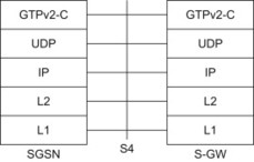
Figure 10.3.6.1 S4 interface.
10.3.7 SGSN ↔ SGSN (S16)
The S16 interface is defined between two SGSNs and this interface exclusively uses GTPv2-C and for 2G/3G accesses only when on an EPS network. The main function of this protocol is to transfer the contexts for individual terminals attached to the EPC network and are thus sent on a per UE basis as in the case of S10 interface. Figure 10.3.7.1 shows the protocol stack for S16 interface.
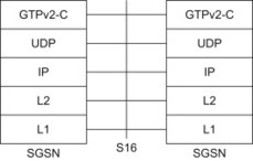
Figure 10.3.7.1 S16 interface.
10.3.8 User plane
The user plane protocols use GTPv1-U as defined in 3GPP TS29.281, [29.281]. This runs over X2-U, S1-U, S4 user plane, S5/S8 user plane and S12 user plane interfaces for GTP variant of the EPS architecture. GTPv1-U is also used for 2G/3G Packet Core (also known as GPRS) over Gn, Gp and Iu-U interfaces. Note that both IPv4 and IPv6 are supported on the transport layer of IP.
10.3.9 eNodeB ↔ Serving GW (S1-U)
The S1-U is the user plane interface carrying user data traffic between the eNodeB and Serving GW received from the terminal. The protocol stack for S1-U is shown in Figure 10.3.9.1.
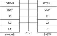
Figure 10.3.9.1 S1-U interface.
10.3.10 UE ↔ eNodeB ↔ Serving GW ↔ PDN GW (GTP-U)
Figure 10.3.10.1 shows end-to-end user plane traffic in case of LTE access and using GTPv1-U protocol stack (over S1-U-S5/S8 GTP variant). As can be seen in Figure 10.3.10.1, the protocol stack on SGi is Application protocol over IP.
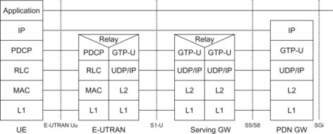
Figure 10.3.10.1 User plane for LTE access (GTP-based S5/S8).
10.3.11 UE ↔ BSS ↔SGSN ↔ Serving GW ↔ PDN GW (GTP-U)
Figure 10.3.11.1 shows end-to-end user plane traffic for the case of 2G access over EPC using the GTPv1-U protocol stack (over S4 and S5/S8 GTP variant). As can be seen in Figure 10.3.11.1, the protocol stack on SGi is Application protocol over IP.
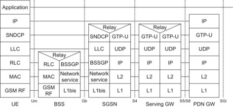
Figure 10.3.11.1 User plane for 2G access (GTP-based S5/S8).
10.3.12 UE ↔ UTRAN ↔ Serving GW ↔ PDN GW (GTP-U)
Figure 10.3.12.1 shows end-to-end user plane traffic in case of 3G access over EPC and using GTPv1-U protocol stack (over Iu-U-S5/S8 GTP variant) and where the SGSN is no longer in the user plane path (direct tunnel established between RNC and Serving GW). As can be seen in Figure 10.3.12.1, the protocol stack on SGi is Application protocol over IP.
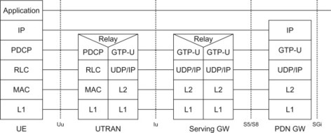
Figure 10.3.12.1 User plane for 3G access with ‘direct tunnel’ (GTP-based S5/S8).
10.3.13 UE ↔ UTRAN ↔ SGSN ↔ Serving GW ↔ PDN GW (GTP-U)
Figure 10.3.13.1 shows end-to-end user plane traffic in case of 3G access over EPC and using GTPv1-U protocol stack (over Iu-U-S5/S8 GTP variant) and where the SGSN is in the user plane path (direct tunnel not used). As can be seen in Figure 10.3.13.1, the protocol stack on SGi is Application protocol over IP.
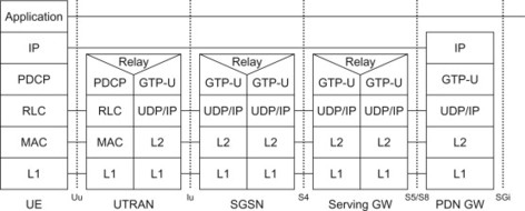
Figure 10.3.13.1 User plane for 3G access without ‘direct tunnel’ (GTP-based S5/S8).
10.4 PMIP-based Interfaces
10.4.1 Serving GW – PDN GW (S5/S8)
10.4.1.1 General
The S5/S8 interface is defined between the Serving GW and the PDN GW. The S5 interface is used in non-roaming scenarios where the Serving GW is located in the home network, or in roaming scenarios with both Serving GW and PDN GW located in the visited network, see Figure 10.4.1.1.1. The latter scenario is also referred to as Local Breakout. The S8 interface is the roaming variant of S5 and is used in roaming scenarios with the Serving GW in the visited network and the PDN GW in the home network.
Figure 10.4.1.1.1 S5/S8 interface.
10.4.1.2 Interface functionality
The S5/S8 interface provides user plane tunnelling and tunnel management between the Serving GW and the PDN GW. It is used for Serving GW relocation due to UE mobility and in case the Serving GW needs to connect to a non-collocated PDN GW for the required PDN connectivity.
10.4.1.3 Protocol
Two protocol alternatives have been specified for the S5/S8 interface; a PMIP-based variant and a GTP-based variant. The protocol stacks for the GTP-based alternative is described in Section 10.3. The protocol stacks for the PMIP-based variant of S5/S8 is shown in Figure 10.4.1.3.1 PMIP-S5-CP (control plane) and Figure 10.4.1.3.2 PMIP-S5-UP (user plane). The Serving GW acts as a Mobile Access Gateway (MAG) for PMIPv6 and the PDN GW acts as an LMA. The user plane is tunnelled using Generic Routing Encapsulation (GRE). The key field extensions of GRE are used, [draft-ietf-netlmm-grekey-option] where the key field value is used to identify a PDN connection.
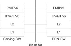
Figure 10.4.1.3.1 Control plane protocol stack for the S5/S8 interface (PMIPv6 variant).
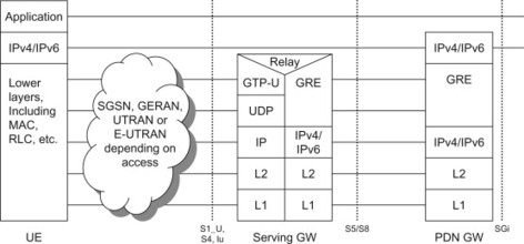
Figure 10.4.1.3.2 User plane protocol stack for the S5/S8 interface (PMIPv6 variant).
The definition of the PMIP-based S5/S8 interface and its functionality is given in 3GPP TS 23.402, [23.402]. The PMIPv6-based protocol for S5/S8 is defined in TS 29.275, [29.275].
10.4.2 Trusted non-3GPP IP access – PDN GW (S2a)
10.4.2.1 General
The S2a interface is defined between an access GW in the trusted non-3GPP access network and the PDN GW. The S2a interface is defined for both roaming and non-roaming scenarios, see Figure 10.4.2.1.1.
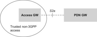
Figure 10.4.2.1.1 S2a interface.
10.4.2.2 Interface functionality
The S2a interface provides user plane tunnelling and tunnel management between the trusted non-3GPP access and the PDN GW. It provides mobility support for mobility within the trusted non-3GPP access and between different accesses.
10.4.2.3 Protocol
The protocol over the S2a interface is based on PMIPv6. The protocol stack for S2a is shown in Figure 10.4.2.3.1 (control plane) and Figure 10.4.2.3.2 (user plane). An Access GW in the trusted non-3GPP access acts as MAG for PMIPv6 and the PDN GW acts as LMA. The user plane is tunnelled using GRE. The key field extensions of GRE are used, [draft-ietf-netlmm-grekey-option] where the key field value is used to identify a PDN connection.
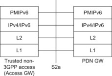
Figure 10.4.2.3.1 Control plane protocol stack for the S2a interface.
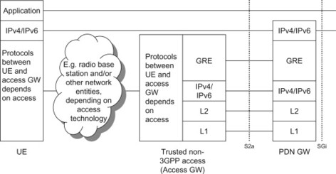
Figure 10.4.2.3.2 User plane protocol stack for the S2a interface.
The definition of the S2a interface and its functionality is given in 3GPP TS 23.402, [23.402]. The PMIPv6-based protocol for S2a is defined in TS 29.275, [29.275].
10.4.3 ePDG – PDN GW (S2b)
10.4.3.1 General
The S2b interface is defined between the ePDG and the PDN GW. The S2b interface is defined for both roaming and non-roaming scenarios, see Figure 10.4.3.1.1.
Figure 10.4.3.1.1 S2b interface.
10.4.3.2 Interface functionality
The S2b interface provides user plane tunnelling and tunnel management between the ePDG and the PDN GW.
10.4.3.3 Protocol
The protocol over the S2b interface is based on PMIPv6. The protocol stacks for S2b is shown in Figure 10.4.3.3.1 (control plane) and Figure 10.4.3.3.2 (user plane). An Access GW in the trusted non-3GPP access acts as an MAG for PMIPv6 and the PDN GW acts as an LMA. The user plane is tunnelled using GRE. The key field extensions of GRE are used, [draft-ietf-netlmm-grekey-option] where the key field value is used to identify a PDN connection.
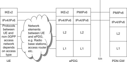
Figure 10.4.3.3.1 Control plane protocol stack for the S2b interface.
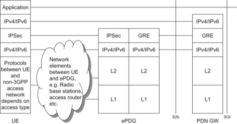
Figure 10.4.3.3.2 User plane protocol stack for the S2b interface.
The definition of the S2b interface and its functionality is given in 3GPP TS 23.402, [23.402]. The PMIPv6-based protocol for S2b is defined in TS 29.275, [29.275].
10.5 DSMIPv6-based Interfaces
10.5.1 UE – PDN GW (S2c)
10.5.1.1 General
The S2c interface is defined between the UE and the PDN GW. The S2c interface is defined for both roaming and non-roaming scenarios, see Figure 10.5.1.1.1.
Figure 10.5.1.1.1 S2c interface.
10.5.1.2 Interface functionality
The S2c interface provides the user plane with related control and mobility support between UE and the PDN GW. This interface is implemented over trusted and/or untrusted non-3GPP Access and/or 3GPP access. Special considerations apply for S2c when the UE is attached over a 3GPP access (see below).
10.5.1.3 Protocol
The protocol over the S2c interface is based on DSMIPv6. The protocol stacks when using S2c over a trusted non-3GPP access is shown in Figure 10.5.1.3.1 while the protocol stack for using S2c over an untrusted non-3GPP access is shown in Figure 10.5.1.3.2. The user plane is tunnelled using IP-in-IPv4/IPv6 encapsulation or using IP-in-UDP-in-IPv4 encapsulation to support NAT traversal.
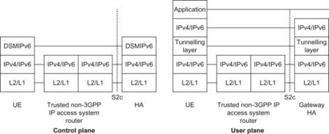
Figure 10.5.1.3.1 Protocol stacks for the control plane and user plane when using S2c over a trusted non-3GPP access.
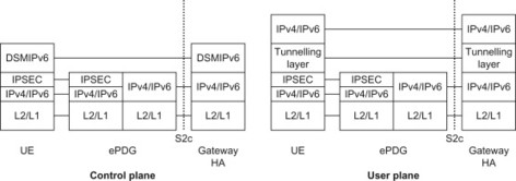
Figure 10.5.1.3.2 Protocol stacks for the control plane and user plane when using S2c over an un-trusted non-3GPP access.
When the UE is connected via a 3GPP access, the UE is considered to be on its home link (in DSMIPv6 sense). There is thus no S2c user plane tunnelling over 3GPP accesses. S2c is used only for DSMIPv6 bootstrapping and DSMIPv6 De-Registration (Binding Update with Lifetime equals zero) when the UE is connected via 3GPP access. More information on these and other DSMIPv6 aspects can be found in, Section 11.3.
The definition of the S2c interface and its functionality is given in 3GPP TS 23.402, [23.402]. The DSMIPv6-based protocol for S2c is defined in TS 24.303, [24.303].
10.6 HSS-related Interfaces and Protocols
10.6.1 General
In this section we describe the interface S6a between the HSS and the MME as well as interface S6d between HSS and SGSN. The interface between the 3GPP AAA server and the HSS is described in Section 10.7.
10.6.2 MME – HSS (S6a) and SGSN – HSS (S6d)
10.6.2.1 General
The interface S6a is defined between the HSS and the MME and the interface S6d is defined between HSS and SGSN. The S6d interface is used in EPS and thus applies to the S4-based SGSN only. For a Gn/Gp-based SGSN, the Gr interface between SGSN and HSS/HLR applies, see Figure 10.6.2.1.1.
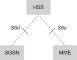
Figure 10.6.2.1.1 S6a and S6d interfaces.
10.6.2.2 Interface functionality
The interfaces between HSS and SGSN as well as between HSS and MME are used for multiple purposes. It allows the MME/SGSN and HSS to:
-
Exchange location information: As described in Section 6.4 and 6.5, the MME/SGSN currently serving the UE is notifying the HSS about the MME/SGSN identity. In some cases, for example if the UE attaches to a new MME/SGSN, the MME/SGSN downloads information from HSS about the MME or SGSN that previously served to UE.
-
Authorize a user to access the EPS: The HSS holds the subscription data including for example the allowed Access Point Names (APNs) and other information related to the user’s authorized services. The subscription profile is downloaded to the MME/SGSN and used when granting a user access to the EPS.
-
Exchange authentication information: As described in Chapter 7 the HSS provides authentication data (the EPS Authentication vector) to the MME/SGSN when the user is being authenticated.
-
Download and handle changes in the subscriber data stored in the server: When the subscriber data in the HSS is modified, for example in case the subscription is withdrawn, or access to certain APNs is withdrawn, the updated subscription data is downloaded to the MME/SGSN currently serving the UE. Based on the updated subscription data, the MME/SGSN may modify the ongoing session, or even detach the UE completely.
-
Upload the PDN GW identity and APN being used for a specific PDN connection. The information about the currently active PDN connections (PDN GW identity and APN) is stored in the HSS to support mobility with non-3GPP accesses.
-
Download the PDN GW identity and APN pairs being stored in HSS for already ongoing PDN connection. This occurs for example during the handover from a non-3GPP access to a 3GPP access.
10.6.2.3 Protocol
The same protocol is used on both S6a and S6d. This S6a/S6d interface protocol is based on Diameter and is defined as a vendor specific Diameter application, where the vendor is 3GPP. The S6a/S6d Diameter application is based on the Diameter base protocol but defines new Diameter commands and attribute-value pairs (AVPs) to implement the functions described in the previous section. Diameter messages over the S6a, S6d interfaces shall use the Stream Control Transmission Protocol (SCTP), [2960] as a transport protocol. The protocol stack is illustrated in Figure 10.6.2.3.1.

Figure 10.6.2.3.1 Protocol stack for S6a/S6d.
The protocol over the S6a/S6d interface, including the S6a/S6d Diameter application is defined in 3GPP TS 29.272, [29.272].
10.7 AAA-related Interfaces
10.7.1 General
The network nodes specific to 3GPP accesses, such as the MME and SGSN, connect directly to HSS. Network entities related to other accesses, for example as described by 3GPP2, are however typically interfacing an AAA server instead. Therefore a 3GPP AAA server is used in the EPC architecture to interface entities related to for example CDMA accesses and other accesses outside the 3GPP family. In order to access for example subscription data and other data available in HSS, the 3GPP AAA server interfaces the HSS via the SWx interface.
The different AAA-related interfaces covered in this section are illustrated in Figure 10.7.1.1. The S6b, STa, SWa and SWm may either connect to the 3GPP AAA server or the 3GPP AAA proxy depending on whether it is a roaming or non-roaming scenario. For the roaming scenario, S6b may connect to the AAA server or AAA proxy depending whether the PDN GW is located in the visited network or in the home network. See Chapter 3 for a more complete description of the architecture alternatives.
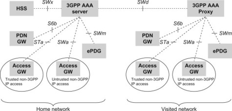
Figure 10.7.1.1 AAA-related interfaces.
10.7.2 AAA server – HSS (SWx)
10.7.2.1 General
The SWx interface is defined between the HSS and the 3GPP AAA server, see Figure 10.7.2.1.1.
Figure 10.7.2.1.1 SWx interface.
10.7.2.2 Interface functionality
The SWx interface is used for subscriber profile management as well as for non-3GPP access-related location management.
Non-3GPP access location management procedures on SWx include the following functionality:
-
AAA server registration: The 3GPP AAA server registers the current 3GPP AAA server address in the HSS for a given user when a new subscriber has been authenticated by the 3GPP AAA server.
-
Upload PDN GW identity and APN: The 3GPP AAA server informs the HSS about the current PDN GW identity and APN being used for a given UE, or that a certain PDN GW and APN pair is no longer used. This occurs for example when a PDN connection is established or closed. This corresponds to the similar functionality as is available on S6a/S6d when the UE is in 3GPP access.
-
PDN GW identity and APN download: The 3GPP AAA server downloads the PDN GW identity and APN information being stored in HSS for already ongoing PDN connections for a given UE. This is for the case when the UE has already been assigned PDN GW(s) due to a previous attach in a 3GPP access (when the UE is handed over from a 3GPP access to a non-3GPP access).
-
AAA-initiated de-registration: The 3GPP AAA server may de-register the currently registered 3GPP AAA server in the HSS for a given user and purge any related non-3GPP user status data in the HSS. This occurs if the UE for some reason has been disconnected from the non-3GPP access.
-
HSS-initiated de-registration: The HSS may initiate a de-registration procedure to purge the UE from the 3GPP AAA server. This happen when the user’s subscription has been cancelled or for other operator-determined reasons. As a result, the 3GPP AAA server should de-activate any UE tunnel in the PDN GW and/or detach the UE from the access network.
The subscriber profile management procedures over SWx include the following functionality:
-
Subscriber profile push: The HSS may decide to send the subscriber profile to a registered 3GPP AAA server. This occurs for example when the subscriber profile has been modified in the HSS and the 3GPP AAA server needs to be updated.
-
Subscriber profile request: The 3GPP AAA server may also request the user profile data from the HSS. This procedure is invoked when for some reason the subscription profile of a subscriber is lost or needs to be updated.
10.7.2.3 Protocol
The SWx interface protocol is based on Diameter and is defined as a vendor specific Diameter application, where the vendor is 3GPP. The SWx Diameter application has its own Diameter application identifier but is re-using Diameter commands from the Diameter Cx/Dx application which is a 3GPP vendor specific application defined for IMS. New AVPs are however defined for the SWx application to implement the functions described above. The protocol stack is illustrated in Figure 10.7.2.3.1.
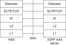
Figure 10.7.2.3.1 Protocol stack for SWx.
The definition of the interface and its functionality is given in 3GPP TS 23.402. The specification of the SWx Diameter application can be found in 3GPP TS 29.273.
10.7.3 Trusted non-3GPP access – 3GPP AAA server/proxy (STa)
10.7.3.1 General
The STa interface is defined between the trusted non-3GPP IP access and the 3GPP AAA server in the non-roaming case. In the roaming case it is defined between the trusted non-3GPP IP access and the 3GPP AAA proxy, see Figure 10.7.3.1.1.
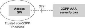
Figure 10.7.3.1.1 STa interface.
10.7.3.2 Interface functionality
The STa interface includes the following functionality to:
-
Authenticate and authorize a user when the user attaches to a trusted non-3GPP IP Access.
-
Transport subscription data such as the APN-AMBR and default QoS profile from the 3GPP AAA server to the trusted non-3GPP IP access. The 3GPP AAA server has in turn received the subscription data from the HSS.
-
Transport mobility parameters that are needed for the S2a interface, that is when PMIPv6 or Mobile IPv4 is used to connect the UE to the EPC. In particular this information may include the PDN GW identity(s) and APN(s) currently allocated to a UE during a previous attach in a 3GPP access.
-
Transport mobility parameters related to the S2c interface, that is when the UE is attaching to EPC using DSMIPv6. In particular the Home Agent IP address or Fully Qualified Domain Name (FQDN) may be sent from the 3GPP AAA server to the gateway of the trusted non-3GPP access for Home Agent discovery based on DHCPv6.
-
To transport information about IP Mobility Mode Selection. This includes both information from the trusted non-3GPP IP access to the 3GPP AAA server/proxy about the mobility features supported by the non-3GPP access (e.g. if the Access GW in the non-3GPP IP access supports MAG functionality for PMIP) as well as information from the 3GPP AAA server/proxy to the Access GW regarding the selected mobility mechanism.
10.7.3.3 Protocol
This STa interface protocol is based on Diameter and is defined as a vendor specific Diameter application, where the vendor is 3GPP. The STa Diameter application is based on Diameter base protocol and also includes commands from the following specifications:
-
The Diameter Network Access Server (NAS) Application which is a Diameter application used for AAA services in the Network Access Server (NAS) environment, [4005].
-
The Diameter EAP application which is a Diameter application to support EAP transport over Diameter, [RFC 4072]. The EAP methods EAP-AKA and EAP-AKA’ may be used as described in Chapter 7.
-
Extensions relevant for PMIPv6 defined in, [draft-ietf-dime-pmip6] and extensions relevant for DSMIPv6 defined in RFC 5447, [5447].
The protocol stack for STa is illustrated in Figure 10.7.3.3.1.
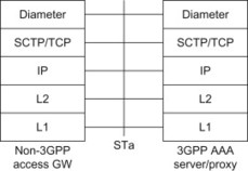
Figure 10.7.3.3.1 Protocol stack for Sta.
The definition of the interface and its functionality is given in 3GPP TS 23.402, [23.402]. The STa Diameter application is defined in TS 29.273, [29.273].
10.7.4 Untrusted non-3GPP IP access – 3GPP AAA server/proxy (SWa)
10.7.4.1 General
The SWa interface is defined between the untrusted non-3GPP IP access and the 3GPP AAA server (non-roaming case) or 3GPP AAA proxy (roaming case), see Figure 10.7.4.1.1.
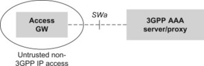
Figure 10.7.4.1.1 SWa interface.
10.7.4.2 Interface functionality
The SWa interface is used for 3GPP-based access authentication and authorization with an untrusted non-3GPP access. It also supports reporting of accounting information generated by the access network.
As described in, Section 7.3 access authentication in untrusted non-3GPP IP access is optional. The reason is that when accessing an untrusted non-3GPP access, the UE will anyway be authenticated and authorized for EPS access using the tunnel procedures with an ePDG (using SWu and SWm interfaces). Use of SWa is therefore optional when a UE accesses an untrusted non-3GPP IP access.
10.7.4.3 Protocol
This SWa interface protocol is based on Diameter and is defined as a vendor specific Diameter application, where the vendor is 3GPP. It is using the Diameter base protocol and includes commands from the following two applications:
-
The Diameter EAP application which is a Diameter application to support EAP transport over Diameter, [4072]. The EAP methods EAP-AKA and EAP-AKA’ may be used as described in Chapter 7.
-
The Diameter Network Access Server (NAS) application which is a Diameter application used for AAA services in the Network Access Server (NAS) environment, [4005], see Figure 10.7.4.3.1.
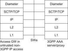
Figure 10.7.4.3.1 Protocol stack for SWa.
The definition of the interface and its functionality is given in 3GPP TS 23.402, [23.402]. The SWa protocol is defined in TS 29.273, [29.273].
10.7.5 ePDG – 3GPP AAA server/proxy (SWm)
10.7.5.1 General
The SWm interface is defined between the ePDG and the 3GPP AAA server or between the ePDG and the 3GPP AAA proxy, see Figure 10.7.5.1.1.
Figure 10.7.5.1.1 SWm interface.
10.7.5.2 Interface functionality
The SWm interface includes the following functionality to:
-
Authenticate and authorize a user at tunnel setup on the SWu interface (i.e. between UE and ePDG).
-
Transport subscription profile data from the 3GPP AAA server to the ePDG. The 3GPP AAA server has in turn received the subscription profile data from the HSS.
-
Transport mobility parameters that are needed for the S2b interface, that is when PMIPv6 is used to connect the UE to the EPC. In particular this information may include the PDN GW identity(s) and APN(s) currently allocated to a UE during a previous attach in a 3GPP access.
-
Transport mobility parameters related to the S2c interface, that is when the UE is attaching to EPC using DSMIPv6. In particular the Home Agent IP address or FQDN may be sent from the 3GPP AAA server to the gateway of the trusted non-3GPP access for Home Agent discovery based on IKEv2.
-
To transport information about IP Mobility Mode Selection. This includes both information from the ePDG to the 3GPP AAA server/proxy about the mobility features supported by the ePDG (e.g. if the ePDG supports MAG functionality for PMIP) as well as information from the 3GPP AAA server/proxy to the ePDG regarding the selected mobility mechanism.
-
To transport session termination indications and requests. This includes both a session termination indication from the ePDG to the 3GPP AAA server/proxy in case the session with the UE has been terminated as well as session termination requests from the 3GPP AAA server/proxy to request the ePDG to terminate a given session.
10.7.5.3 Protocol
This SWm interface protocol is based on Diameter and is defined as a vendor specific Diameter application, where the vendor is 3GPP. The SWm Diameter application is based on Diameter base protocol and includes commands from the following specifications:
-
The Diameter Network Access Server (NAS) Application which is a Diameter application used for AAA services in the Network Access Server (NAS) environment, [4005].
-
The Diameter EAP application which is a Diameter application to support EAP transport over Diameter, [4072]. The EAP methods EAP-AKA and EAP-AKA’ may be used as described in Chapter 7.
-
Extensions relevant for PMIPv6 defined in, [draft-ietf-dime-pmip6] and extensions relevant for DSMIPv6 defined in RFC 5447, [5447].
The protocol stack for SWm is illustrated in Figure 10.7.5.3.1.
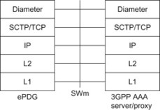
Figure 10.7.5.3.1 Protocol stack for SWm.
The definition of the interface and its functionality is given in 3GPP TS 23.402, [23.402]. The SWm Diameter application is defined in TS 29.273, [29.273].
10.7.6 PDN GW – 3GPP AAA server/proxy (S6b)
10.7.6.1 General
The S6b interface is defined between the PDN GW and the 3GPP AAA server (for non-roaming case, or roaming with home routed traffic to PDN GW in home network) and between the PDN GW and the 3GPP AAA proxy (for roaming case with PDN GW in the visited network, i.e. local breakout), see Figure 10.7.6.1.1.
Figure 10.7.6.1.1 S6b interface.
10.7.6.2 Interface functionality
The S6b interface is not utilized when the UE is attached in GERAN, UTRAN or E-UTRAN. In these cases it is instead the S6a/S6d interfaces that provide the needed functionality as described in Section 10.6. When a UE attaches over another access not in the 3GPP family of accesses, S6b provides the functionality described below.
The S6b interface is used to inform the 3GPP AAA server/proxy about current PDN GW identity and APN being used for a given UE, or that a certain PDN GW and APN pair is no longer used. This occurs for example when a PDN connection is established or closed. (The information is then forwarded to the HSS via the SWx interface.) S6b may be used to retrieve specific subscription-related parameters such as a subscribed QoS profile for non-3GPP accesses.
The above functionality of S6b is common for all mobility protocols that can be used when a UE attaches over a non-3GPP access, that is PMIPv6-based S2a or S2b, Mobile IPv4-based S2a or DSMIPv6-based S2c.
Other main functions of the S6b interface depend on what mobility protocol is used when connecting a UE to the EPC.
When the UE attaches to the EPC using the DSMIPv6-based S2c interface, the S6b interface is also used to authenticate and authorize the UE. It is also used to indicate to the PDN GW that a PDN GW re-allocation shall be performed (see TS 23.402 for more details on the PDN GW re-allocation procedure and the scenarios when it is used). When S2c is used the S6b interface can furthermore be used to transport a session termination indication from the 3GPP AAA server/proxy to the PDN GW, to trigger a termination of a PDN connection (the 3GPP AAA server/proxy may receive a trigger for sending the termination indication from the HSS via the SWx interface).
When the UE attaches using the Mobile IPv4-based S2a interface, S6b is also used to authenticate and authorize the Mobile IPv4 Registration Request message that was sent by the UE.
10.7.6.3 Protocol
This S6b interface protocol is based on Diameter and is defined as a vendor specific Diameter application, where the vendor is 3GPP. The S6b Diameter application is based on Diameter base protocol with the following additions:
-
The Diameter Network Access Server (NAS) Application which is a Diameter application used for AAA services in the Network Access Server (NAS) environment, [4005].
-
Extensions relevant for PMIPv6 defined in, [draft-ietf-dime-pmip6] and extensions relevant for DSMIPv6 defined in RFC 5447, [5447].
-
The Diameter EAP application which is a Diameter application to support EAP transport over Diameter, [4072]. The EAP method EAP-AKA is be used as described in Chapter 7.
The protocol stack for S6b is illustrated in Figure 10.7.6.3.1.
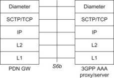
Figure 10.7.6.3.1 Protocol stack for S6b.
The definition of the interface and its functionality is given in 3GPP TS 23.402, [23.402]. The S6b Diameter application is defined in TS 29.273, [29.273].
10.7.7 3GPP AAA proxy – 3GPP AAA server/proxy (SWd)
10.7.7.1 General
The SWd interface is defined between the 3GPP AAA proxy and the 3GPP AAA server. The SWd interface is used in roaming scenarios where the 3GPP AAA proxy is located in the visited network and the 3GPP AAA server is located in the home network.
The 3GPP AAA proxy acts as a Diameter proxy agent and forwards Diameter commands between the Diameter client and the Diameter server, see Figure 10.7.7.1.1.
Figure 10.7.7.1.1 SWd interface.
10.7.7.2 Interface functionality
The prime purpose of the protocols crossing this interface is to transport AAA signalling between home and visited networks in a secure manner. The SWd interface may be used in connection with any of the interfaces SWa, STa, SWm and S6b depending on the particular roaming scenario. The functionality of those interfaces applies to SWd as well.
10.7.7.3 Protocol
The SWd interface uses the Diameter applications and extensions that are used on the SWa, STa, SWm and S6b interfaces. There is thus no separate Diameter application defined for the SWd interface, instead the SWa, STa, SWm and S6b applications are proxied onto SWd. The same Diameter commands as defined for the SWa, STa, SWm and S6b interfaces are used on SWd as well, depending on the specific roaming scenario.
The protocol stack for SWd is illustrated in Figure 10.7.7.3.1.
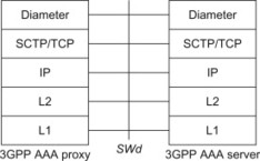
Figure 10.7.7.3.1 Protocol stack for SWd.
The definition of the interface and its functionality is given in 3GPP TS 23.402, [23.402]. The SWd protocol is defined in TS 29.273, [29.273].
10.8 PCC-related Interfaces
10.8.1 General
The PCRF-related interfaces include Gx, Gxa, Gxc, Rx, S9 and Sp. See Section 8.2 for more details on PCC and where these interfaces are located in the architecture. Below we will walk through the different interfaces related to PCC and briefly describe each of them.
10.8.2 PCEF – PCRF (Gx)
10.8.2.1 General
The Gx interface is defined between the PCEF (PDN GW) and the PCRF, see Figure 10.8.2.1.1.
Figure 10.8.2.1.1 Gx interface.
10.8.2.2 Interface functionality
The main purpose of the Gx interface is to support PCC rule handling and event handling for PCC.
PCC rule handling over the Gx interface includes the installation, modification and removal of PCC rules. All these three operations can be made upon any request coming from the PCEF or due to some internal decision in the PCRF.
The event handling procedures allows the PCRF to subscribe to those events it is interested in. The PCEF then reports the occurrence of an event to the PCRF.
For more details on PCC rule handling and event reporting, see Section 8.2.
10.8.2.3 Protocol
This Gx protocol is based on Diameter and is defined as a vendor specific Diameter application, where the vendor is 3GPP. 3GPP Rel-8 is re-using the Gx Diameter application that was defined for Gx in 3GPP Rel-7. Only minor updates have been done to Gx in Rel-8. The Gx Diameter application is based on the Diameter base protocol and is also incorporating commands and AVPs from the Diameter Credit Control Application (DCCA) defined in RFC 4006, [4006].
The protocol stack for Gx is illustrated in Figure 10.8.2.3.1.
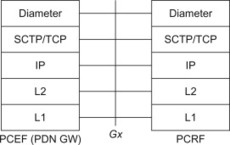
Figure 10.8.2.3.1 Protocol stack for Gx.
The definition of the Gx interface and its functionality is given in 3GPP TS 23.203 [, 23.203]. The Gx Diameter application is defined in TS 29.212 [29.212].
10.8.3 BBERF – PCRF (Gxa/Gxc)
10.8.3.1 General
The Gxa and Gxc interfaces are located between the PCRF and the BBERF. Gxc applies when the BBERF is located in the Serving GW and Gxa applies when the BBERF is located in an Access GW in a trusted non-3GPP IP access, see Figure 10.8.3.1.1.
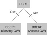
Figure 10.8.3.1.1 Gxa/Gxc interfaces.
10.8.3.2 Interface functionality
The main purpose of the Gxa and Gxc interfaces is to support QoS rule and event handling for PCC. This is similar to the Gx interface with the difference that the Gx interface handles PCC rules instead while Gxa and Gxc handle QoS rules.
For more details on QoS rule handling and event reporting, see Section 8.2.
10.8.3.3 Protocol
The protocol over the Gxa and Gxc interfaces is based on Diameter. A new Diameter vendor specific application, the Gxx Diameter application, has been defined and is used on both Gxa and Gxc. The Gxx Diameter application is, similar to the Gx application, based on the Diameter base protocol and incorporating commands and AVPs from the DCCA defined in RFC 4006, [4006].
The protocol stack for Gxa and Gxc is illustrated in Figure 10.8.3.3.1.
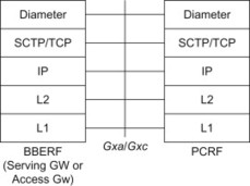
Figure 10.8.3.3.1 Protocol stack for Gxa/Gxc.
The definition of the Gxa/Gxc interface and its functionality is given in 3GPP TS 23.203, [23.203]. The Gxx Diameter application is defined in TS 29.212 [29.212].
10.8.4 PCRF – AF (Rx)
10.8.4.1 General
The Rx interface is defined between the PCRF and the AF, see Figure 10.8.4.1.1.
Figure 10.8.4.1.1 Rx interface.
10.8.4.2 Interface functionality
The main purpose of the Rx interface is to transfer session information from the AF to the PCRF. Rx is also used by the AF to subscribe to notifications about traffic plane events, for example that an IP session has been closed or that the UE has handed over to a different access technology. The PCRF will notify the AF of the occurrence of a subscribed traffic plane event.
For more details on Rx procedures, see Section 8.2.
10.8.4.3 Protocol
The protocol over the Rx interface is based on Diameter. 3GPP Rel-8 is re-using the Rx Diameter application that was defined for Rx in 3GPP Rel-7. The Rx Diameter application is based on the Diameter base protocol and is also incorporating commands from the Diameter Network Access Server (NAS) Application defined in RFC 4005, [4005]. It can be noted however that the concept of a NAS (Network Access Server) is not used with Rx, it is merely the Diameter NAS application commands that are re-used for the Rx protocol, not its functional framework.
The protocol stack for Rx is illustrated in Figure 10.8.4.3.1.
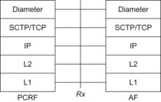
Figure 10.8.4.3.1 Protocol stack for Rx.
The definition of the Rx interface and its functionality is given in 3GPP TS 23.203, [23.203]. The Rx Diameter application is defined in TS 29.214, [29.214].
10.8.5 PCRF – PCRF (S9)
10.8.5.1 General
The S9 interface is defined between the PCRF in the home network (H-PCRF) and a PCRF in the visited network (V-PCRF). S9 is an inter-operator interface and is only used in roaming scenarios, see Figure 10.8.5.1.1.
Figure 10.8.5.1.1 S9 interface.
10.8.5.2 Interface functionality
The main purpose of the S9 interface is to transfer policy decisions (i.e. PCC rules or QoS rules) generated in the home network into the visited network and transport the events that may occur in the visited network to the home network.
The S9 interface can also be used to transfer session information in specific roaming scenarios. The two main roaming scenarios are the home routed case (with PDN GW/PCEF in the home network) and the local breakout (with PDN GW/PCEF in the visited network). In the Local Breakout case, it is furthermore possible to use an AF either in the home network or in the visited network. When Local Breakout is used and the AF is in the visited network, the S9 interface carries service session information from the V-PCRF to the H-PCRF (see Section 8.2 for further details regarding PCC usage in roaming scenarios).
10.8.5.3 Protocol
The protocol over the S9 interfaces is based on Diameter. Two 3GPP vendor specific Diameter applications are used over the S9 interface: the S9 application and the Rx application.
The S9 Diameter application is a new vendor-specific application defined in 3GPP Rel-8. It is based on the Diameter base protocol and incorporating commands and AVPs from the DCCA defined in RFC 4006, [4006].
The Rx Diameter application is described above for the Rx interface. It is used over the S9 interface in case of Local Breakout with the AF in the visited network, as described above.
The protocol stack for S9 is illustrated in Figure 10.8.5.3.1.
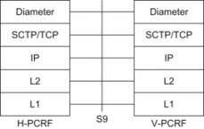
Figure 10.8.5.3.1 Protocol stack for S9.
The definition of the S9 interface and its functionality is given in 3GPP TS 23.203, [23.203]. The protocols over the S9 interface, including the S9 Diameter application, are defined in TS 29.215 [, 29.214]. The Rx Diameter application is defined in TS 29.214, [29.214].
10.8.6 SPR – PCRF (Sp)
10.8.6.1 General
The Sp interface is defined between the PCRF and the Subscriber Profile Repository (SPR), see Figure 10.8.6.1.1.
Figure 10.8.6.1.1 Sp interface.
10.8.6.2 Interface functionality
The Sp interface is used to transport subscription data from the SPR to the PCRF. The PCRF may request subscription data for a given user. The SPR may also notify the PCRF in case the subscription data has been modified.
The SPR may contain subscription data related to the transport level policies for the access network. The details regarding the subscription data contained in the SPR have not been further specified. A reason for not specifying the detailed subscription data is that the policies may depend significantly on the operator’s business models and the types of subscriptions and services offered. It is thus reasonable to avoid detailed specification in order not to put unnecessary restrictions on the type of policies that can be kept in the SPR.
10.8.6.3 Protocol
The Sp interface and its functionality are specified in 3GPP TS 23.203, [23.203].
The protocol over the Sp interface is however not specified.
10.9 EIR-related Interfaces
10.9.1 MME-EIR and SGSN-EIR interfaces (S13 and S13’)
10.9.1.1 General
The interface S13 is defined between the Equipment Identity Register (EIR) and the MME and the interface S13' is defined between EIR and SGSN. The S13' interface applies to the S4-based SGSN only, see Figure 10.9.1.1.1.
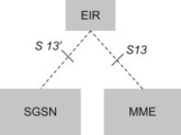
Figure 10.9.1.1.1 S13 and S13' interfaces.
10.9.1.2 Interface functionality
The S13 and S13' interfaces between the MME and the EIR and between the SGSN and the EIR respectively are used to check the status of the UE (e.g. if it has been reported stolen). The MME or SGSN checks the ME Identity by sending the Equipment Identity to an EIR and analysing the response.
10.9.1.3 Protocol
The same protocol is used on both S13 and S13'. This protocol is based on Diameter and is defined as a vendor specific Diameter application, where the vendor is 3GPP. The S13/S13' Diameter application is based on the Diameter base protocol but defines new Diameter commands and AVPs to implement the functions described above. Diameter messages over the S13 and S13' interfaces use the SCTP, [2960] as a transport protocol. The protocol stack is illustrated in Figure 10.9.1.3.1.
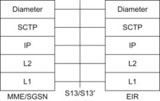
Figure 10.9.1.3.1 Protocol stack for S13/S13'.
The protocol over the S13/S13' interface, including the S13/S13' Diameter application is defined in 3GPP TS 29.272, [29.272].
10.10 I-WLAN-related Interfaces
10.10.1 UE – ePDG (SWu)
10.10.1.1 General
The SWu interface is defined between the UE and the ePDG. The interface runs over an un-trusted non-3GPP IP Access, see Figure 10.10.1.1.1.
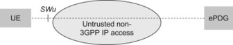
Figure 10.10.1.1.1 SWu interface.
10.10.1.2 Interface functionality
The SWu interface supports procedures for establishment or disconnection of an end-to-end tunnel between the UE and the ePDG. The tunnel establishment is always initiated by the UE, whereas the tunnel disconnection can be initiated by the UE or the ePDG. The SWu interface also supports tunnel modification procedures in order to update the tunnel in case the UE has acquired a new IP address from the un-trusted non-3GPP IP Access, for example in case the UE has moved to another un-trusted non-3GPP IP Access. For further details on tunnel management over un-trusted non-3GPP IP Access, see Section 7.3.
10.10.1.3 Protocol
The tunnel between UE and ePDG is an IPsec tunnel. The UE and ePDG use IKEv2 to establish the IPSec security association (SA) for the tunnel.
The UE uses standard DNS mechanisms in order to select a suitable ePDG. As input to the DNS query, the UE creates a FQDN based on the operator identity. As a reply from the DNS system, the UE receives one or more IP addresses of suitable ePDG(s). Once the ePDG has been selected, the UE initiates the IPsec tunnel establishment procedure using the IKEv2 protocol. Public key signature-based authentication with certificates, as specified for IKEv2, is used to authenticate the ePDG. EAP-AKA within IKEv2 is used to authenticate the UE. As part of the IKEv2 procedure, an IPSec SA is established. IPSec Encapsulated Security Payload (ESP) in tunnel mode shall be used for the IPSec tunnel between the UE and the ePDG.
SWu also supports the mobility extensions for IKEv2 defined by MOBIKE, [4555]. This allows the IPSec SA to be updated in case the UE acquires a new IP address in the un-trusted non-3GPP IP Access.
For further details on IKEv2, MOBIKE and ESP, see Section 11.9.
The protocol stack for SWu is illustrated in Figure 10.10.1.3.1.
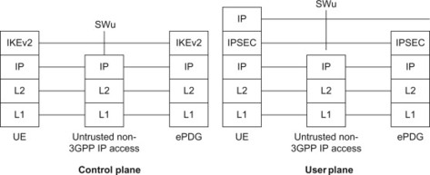
Figure 10.10.1.3.1 SWu-PROTO. Protocol stack for SWu.
The tunnel management procedures for SWu are defined in TS 33.402, [33.402].
10.11 ANDSF-related Interfaces
The Access Network Discovery and Selection Function (ANDSF) is a mechanism that allows the UE to be provided with relevant parameters for intersystem mobility policy and access network discovery. This is done using the S14 interface, which utilizes Open Mobile Alliance (OMA) Device Management (DM). A brief outline of OMA DM is provided below in order to place the discussion regarding the ANDSF-UE interface in the correct context. A detailed description of OMA DM is beyond the scope of this book and the interested reader is referred to, [Brenner, 2008]. A general overview of ANDSF can be found in, Section 6.4.
The OMA DM v1.2 specifications are based on the OMA DM v1.1.2 specifications and make use of the OMA SyncML Common v1.2 specifications as specified in the OMA SyncML Common specifications Enabler Release Definition for SyncML (ERELDSC).
DM is the technology that allows the ANDSF to configure the UE on behalf of the operator and the end-user. Using DM, the ANDSF remotely sets parameters via the use of a Managed Object (MO). The MO is organized in nodes, interior nodes and leaf nodes. The leaf nodes contain the actual parameter values, see Figure 10.11.1. The ANDSF MO contains nodes related to Policy, Discovery Information and UE Location. There is also an additional node defined, Ext, for vendor-specific requirements. These are discussed briefly below:
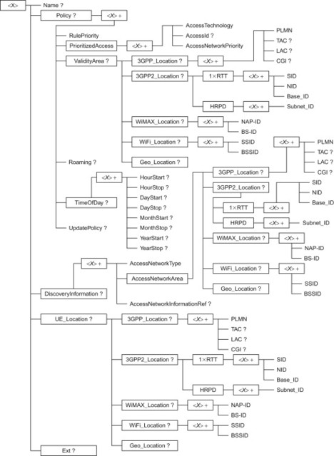
Figure 10.11.1 ANDSF MO.
10.11.1 Policy node
The policy node acts as a placeholder for policies related to intersystem mobility, including the rules and also the priority in which the policies should be applied. It also allows the ANDSF to set a particular access technology as the prioritized access, meaning that this is the one that should be searched for first, including the access network ID. Also included within the Policy node is the Validity area for a particular rule; this is used in the case where a particular rule is applicable to a particular location that the UE may find itself in.
With regard to Validity Areas, these can be different for different access networks, as a result, there are leaves that describe the validity areas and rules associated with them for each radio access technology types; 3GPP, 3GPP2, WiMAX and WiFi (WLAN).
In the case where a UE is roaming, the roaming leaf contains roaming conditions that should be applied in this case. The UE shall only apply such rules, however, if the UE’s roaming state matches the one specified in the roaming value.
Particular rules may be applicable at a certain time of day and as a result there is also a leaf named TimeOfDay that handles this scenario.
In the case that the UE finds itself in a situation where it feels that a rule is no longer valid, it uses the UpdatePolicy leaf to determine whether it needs to request an update of its intersystem mobility policy or not.
10.11.2 Discovery Information node
Using the Discovery Information node, an Operator may provide information on the access networks that are available for a UE to connect to. The UE, meanwhile, may use this information in order to decide which access network to connect to.
The Discovery Information node, therefore, provides information regarding the type of access network, the area that the access network covers. The leaf describing the access network areas again covers all of the different network access types; 3GPP, 3GPP2, WiMAX, WiFi (WLAN). It also covers the use of Geo_Location, which acts as a placeholder for the geographic location of one or more access networks.
10.11.3 UE location node
The UE Location node acts as a placeholder for location descriptions; a UE therefore inserts information regarding all of the access networks that it can discover into this node. For 3GPP networks, this includes: PLMN, Tracking Area Code, Location Area Code and Cell Global Identity. For 3GPP2 networks, this includes SID, NID and Base ID. Whilst for WiMAX networks, UE Location includes: NAP-ID and BS-ID. For WLAN networks, SSID and BSSID are captured.
10.11.4 Ext node
Ext is the node where vendor-specific information about the ANDSF MO is placed. For the purposes of this node, vendor means application vendor, device vendor, etc. This is generally indicated by a vendor-specific name under the Ext node. As can be expected, since this is a vendor-specific node, the leaves under the Ext node are left undefined. If a vendor wishes to utilize extensions, they define the interior nodes and leaves themselves. These are therefore naturally not within in the scope of the standardization.
The MO for the transfer of intersystem mobility policy between the ANDSF and the UE is shown in Figure 10.11.1. For further details on the ANDSF MO see 3GPP TS 24.312, [24.312].
10.12 HRPD IW-related Interfaces
10.12.1 Optimized handover and related interfaces (S101 and S103)
In order to support optimized handover between LTE and eHRPD networks, as explained in preceding chapter, one control plane (S101) and one user plane (S103) interface have been added to the architecture. Below we describe the functions and protocol supported over these two interfaces.
10.12.2 MME ↔ eHRPD access network (S101)
S101 is a tunnel between MME and eHRPD Access network where messages are carried over the serving access network towards a target access network (where the handover may occur) in order for preparation for handover via pre-registration, then maintain the resources via session maintenance and then the actual handover. These are messages tunneled over S101-AP where the GTPv2-C protocol functions are used with explicit utilization for S101 interface. The GTPv2-C message type used for S101 are as follows:
| Message Type value (Decimal) | Message |
| 0 | Reserved |
| 1 | Echo Request |
| 2 | Echo Response |
| 3 | Version Not Supported Indication |
| 4 | Direct Transfer Request message |
| 5 | Direct Transfer Response message |
| 6 | Notification Request message |
| 7 | Notification Response message |
| 8–24 | For future S101 interface use |
| 25–31 | Reserved for Sv interface |
| 32–255 | Reserved for GTPv2-C spec |
The protocol itself is segmented to provide the pre-configured tunnel via Path management general messages and then for specific messages used for information transfer over the control plane, see Figure 10.12.2.1.
Figure 10.12.2.1 S101 interface.
3GPP TS 29.276, [29.276] and TS 29.274, [29.274] describe the details for the messages. Procedures are covered in TS 23.402, [23.402].
The messages carried over this interface is not modified by MME but rather forwarded to/from the source and the target access network (in this case between eNodeB and HRPD AN). Each message must have unique identifier (also known as Session Identifier) to be able to identify uniquely in a global network the individual terminal the message is destined to or coming from.
The pre-configured tunnel carries messages from the MME or eHRPD access network towards its peer in the target network using Direct Transfer Message and Response. Depending on where the message is originating, the content is according to that specific access network (e.g. if an HRPD message is to be tunnelled then this message shall be carried over a transparent container), see Figure 10.12.2.2.
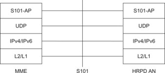
Figure 10.12.2.2 Protocol stack for S101.
In case of Notification Request Message, the information mainly carries events such as completion of handover process.
The GTPv2-C Path management and Reliability procedures are used to manage the pre-configured tunnel S101.
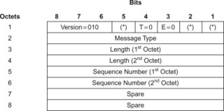
The S101 message header takes the following form (Bits marked by * are spare and set to zero):
Examples of Direct Transfer Message information elements are described below. One can see the parameter usage during the optimized handover procedure described in a later Chapter 12 of the book.
| Information element | Presence requirement |
| IMSI | Mandatory |
| HRPD Sector ID | Conditional |
| S101 Transparent Container | Mandatory |
| PDN GW PMIP GRE Tunnel Info | Conditional |
| S103 GRE Tunnel Info | Conditional |
| S103 HSGW IP Address | Conditional |
| Handover Indicator | Conditional |
| Tracking Area Identity | Conditional |
| Recovery | Conditional |
| Private Extension | Optional |
Note that for the interested reader, the 3GPP TS 29.276, [29.276] is the specification for S101.
10.12.3 Serving GW ↔ HSGW (S103)
The S103 interface from the Serving GW to the HSGW in the CDMA HRPD network, see Figure 10.12.3.1.
Figure 10.12.3.1 S103 interface.
This interface provides support for forwarding of downlink data during handover from LTE to HRPD. The purpose of this interface is to reduce loss of user data during the handover procedure. Signalling procedures and parameters available on the S101 interface are used to set up GRE tunnel on the S103 interface. For details on GRE tunnel, see Section 11.6 for the overview and usage of GRE. The protocol stack for S103 is described in Figure 10.12.3.2.
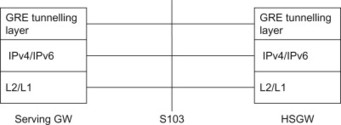
Figure 10.12.3.2 Protocol stack for S103.
S103 interface must be able to identify the user data traffic on a per terminal and per PDN connection basis.
10.13 Interface to External Networks
10.13.1 General
The SGi interface is defined between the PDN GW and external IP networks (also called ‘PDNs’) as shown in Figure 10.13.1.1. The external networks may be Internet and/or Intranets and IPv4 and/or IPv6 may be used.
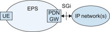
Figure 10.13.1.1 IP network interworking.
The PDN GW is the access point of the EPS and the EPS will look like any other IP network or subnetwork. From the external IP network’s point of view, the PDN GW is seen as a normal IP router.
10.13.2 Functions
Access to Internet, Intranet or an ISP involves functions such as IPv4 address allocation, IPv6 address autoconfiguration, and may also involve specific functions such as authentication, authorization, secure tunnelling to Intranet/ISP.
An operator may offer direct transparent access to the Internet and operator services and will in that case offer at least basic ISP functions. An operator may also offer so called non-transparent access to an Intranet or ISP.
In both the transparent and non-transparent case the UE is given an IPv4 address and/or an IPv6 prefix. The difference is that in the transparent case the IP addresses belong to the operator while in the non-transparent case the addresses belong to the Intranet/ISP addressing space.
IPv4 address and/or IPv6 prefix are assigned either statically tied to the subscription or dynamically allocated at PDN connectivity establishment. This IPv4 address and/or IPv6 prefix is used for packet forwarding between the Internet and the PDN GW and within the packet domain. With IPv6, Stateless Address Autoconfiguration shall be used to assign an IPv6 address to the UE. The PDN GW may use a local IP address pool, or use DHCP or AAA protocols to retrieve UE IP addresses from the external IP network. For more information on IP address allocation for different cases see 3GPP TS 29.061, [29.061] and 23.401, [23.401].
The PDN GW prevents IP spoofing by verifying the source IP address of the IP packets issued by the UE and compare it against the allocated address.
To support IMS the PDN GW will also need to provide a list of P-CSCF addresses to the UE on request. The UE need this information in order to register for IMS services. In addition IMS requires a bearer for the IMS signalling and bearers for media when IMS sessions are established. This means that PDN GW needs to be configured to allow the IMS signalling and it need to support the Gx interface to the PCRF in order to allocated bearers for the IMS media flows.