
Chapter 11 Protocols
11.1 Introduction
This chapter provides an overview of the main protocols used in the EPS with the aim to give a basic overview of these protocols and their basic properties.
11.2 GPRS Tunnelling Protocol Overview
The original version of the GTP protocol is what the GSM standards developed to cater to the specific needs such as mobility and bearer management and tunnelling of user data traffic for GPRS. Then 3GPP further enhanced GTP for usage in 3G UMTS. During the development of EPS, the GTP track of the architecture was enhanced considerably to improve the bearer handling and thus the GTP control plane protocol was upgraded to GTPv2-C.
The two main components of GTP are the control plane part of GTP (GTP-C) and the user plane part of GTP (GTP-U). GTP-C is used to control and manage tunnels for individual terminals connecting to the network in order to establish user data path. For the GTP-U uses a tunnel mechanism to carry the user data traffic. There also exists GTP', which is defined under the GTP protocol umbrella for the purpose of charging, but in this book we will not discuss this legacy protocol usage of GTP. There exists three versions of GTP-C: GTPv0, GTPv1 and GTPv2 and there exists two versions of GTP-U: GTPv0 and GTPv1. In this book we will provide some background on GTPv1-C for better understanding of GTPv2-C which is used exclusively for EPS. We will also discuss some details on GTPv1-U.
In order to understand the functions of the GTP protocol, it is useful to have a look at how GTP has been used in GPRS and 3G Packet Core. Figure 11.2.1 illustrates the interfaces that use GTP.
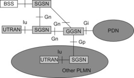
Figure 11.2.1 GTP interfaces for GPRS.
In case of GPRS and 3G packet core, the Gn interface between SGSNs and between SGSN and GGSN (when the entities are within an operator’s PLMN) and Gp interface between SGSN and GGSN (inter-PLMN or inter-operator may be more common term) support GTPv1-C and GTPv1-U protocols. For 3G Packet core using WCDMA/HSPA radio accesses, Iu supports GTPv1 user plane protocol (Figure 11.2.2).
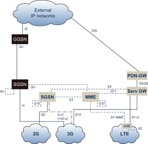
Figure 11.2.2 GTP interfaces for EPS.
In case of EPS, the interfaces between SGSN and MME, between MMEs, between SGSNs, between Serving GW and PDN GW and between Serving GWs use the GTPv2-C and the interface between HRPD Access Network and MME uses GTPv2-C tunnels to carry the tunnelled messages. The GTPv1-U is used between eNodeB and Serving GW, between RNC and Serving GW and between SGSN and Serving GW as well as between Serving GWs. Thus the GTPv2-C is used on S3, S4, S5, S8, S10, S11 and S16 interfaces and GTPv1-U is used on S1-U, Iu-U, S4, S5, S8, S12 and X2-U interfaces.
So what is this protocol suite and how does it work? As can be easily seen from the 3GPP architecture, the entities supporting the GTP protocol need to support one to many and many to many relationships with each other. A single SGSN must beable to connect to multiple RNCs, SGSNs as well as many GGSNs within and between different operators' networks. Similarly, a GGSN must be able to connect to multiple SGSNs from different operators' networks spanning significant geographical areas in order to support its own subscribers who may be in their home network or in a roaming partner’s network. Development of GTP protocol caters to such diverse deployment requirements that are cornerstone for success of mobile systems worldwide.
If we look at the original GTP message structure (see Table 11.2.1), it becomes quite obvious that it serves to manage a cellular network by developing and grouping messages according to the functional needs of a cellular system. Then when we look at the GTPv2 messages developed for EPS (see Table 11.2.2) then we clearly see the evolution of the protocol in a more generic manner catering to more flexible bearer management as well as simplified/unified network elements interactions and support for mobility/common core functions for non-3GPP access networks and better error/failure/network management as well as restoration and recovery handling for network elements such as MME, Serving GW/PDN GW. The key functions that GTP was built upon and then additions from EPS can be categorised as below:
-
Mobility Management: The set of messages created as part of this function includes managing mobile device’s identification and maintain presence/status among various network elements in a coordinated manner, handling data transfer between entities during/at handover/relocation of the mobile terminal.
-
Tunnel Management: Involves creation and deletion of the end user’s session and creation, modification and deletion of bearers established during the period the user is connected and actively involved in services by the network. Simply stated, these messages keep the user’s different service requirements maintained in the network as the user moves around within and between PLMNs.
-
Service specific Functions: For GTPv1 it includes mainly support of MBMS related functions. For GTPv2, during the writing of this book, MBMS service is being developed and impacts if any on GTPv2 is not yet addressed. GTPv2 provides messages in order to function CS Fallback, Optimized handover with 3GPP2, non-3GPP mobility.
-
Mobile Terminal information transfer: For GTPv2 this is incorporated within Mobility Management and is only supported for GERAN/UTRAN accesses.
-
System maintenance(path management/error handling/restoration and recovery/trace): Supporting network level functions in order to handle overall robustness of the tunnels and recover from failure in network entities. These messages (such as Echo Request/Response) have been supported in GTPv1 and now in GTPv2, but wherever possible, for GTPv2 improvements have been made in error handling and recovery procedures.
Table 11.2.1 GTPv1 Control plane Messages (GPRS).
| Message Type value (Decimal) | Message | GTP-C |
| 0 | For future use. Shall not be sent. If received, shall be treated as an Unknown message | |
| 1 | Echo Request | X |
| 2 | Echo Response | X |
| 3 | Version Not Supported | X |
| 4 | Node Alive Request | |
| 5 | Node Alive Response | |
| 6 | Redirection Request | |
| 7 | Redirection Response | |
| 8–15 | For future use. Shall not be sent. If received, shall be treated as an Unknown message | |
| 16 | Create PDP Context Request | X |
| 17 | Create PDP Context Response | X |
| 18 | Update PDP Context Request | X |
| 19 | Update PDP Context Response | X |
| 20 | Delete PDP Context Request | X |
| 21 | Delete PDP Context Response | X |
| 22 | Initiate PDP Context Activation Request | X |
| 23 | Initiate PDP Context Activation Response | X |
| 24–25 | For future use. Shall not be sent. If received, shall betreated as an Unknown message | |
| 26 | Error Indication | |
| 27 | PDU Notification Request | X |
| 28 | PDU Notification Response | X |
| 29 | PDU Notification Reject Request | X |
| 30 | PDU Notification Reject Response | X |
| 31 | Supported Extension Headers Notification | X |
| 32 | Send Routeing Information for GPRS Request | X |
| 33 | Send Routeing Information for GPRS Response | X |
| 34 | Failure Report Request | X |
| 35 | Failure Report Response | X |
| 36 | Note MS GPRS Present Request | X |
| 37 | Note MS GPRS Present Response | X |
| 38–47 | For future use. Shall not be sent. If received, shall be treated as an Unknown message | |
| 48 | Identification Request | X |
| 49 | Identification Response | X |
| 50 | SGSN Context Request | X |
| 51 | SGSN Context Response | X |
| 52 | SGSN Context Acknowledge | X |
| 53 | Forward Relocation Request | X |
| 54 | Forward Relocation Response | X |
| 55 | Forward Relocation Complete | X |
| 56 | Relocation Cancel Request | X |
| 57 | Relocation Cancel Response | X |
| 58 | Forward SRNS Context | X |
| 59 | Forward Relocation Complete Acknowledge | X |
| 60 | Forward SRNS Context Acknowledge | X |
| 61–69 | For future use. Shall not be sent. If received, shall be treated as an Unknown message | |
| 70 | RAN Information Relay | X |
| 71–95 | For future use. Shall not be sent. If received, shall be treated as an Unknown message | |
| 96–105 | MBMS | X |
| 106–111 | For future use. Shall not be sent. If received, shall be treated as an Unknown message | |
| 112–121 | MBMS | X |
| 122–127 | For future use. Shall not be sent. If received, shall be treated as an Unknown message | |
| 128 | MS Info Change Notification Request | X |
| 129 | MS Info Change Notification Response | X |
| 130–239 | For future use. Shall not be sent. If received, shall be treated as an Unknown message | |
| 240 | Data Record Transfer Request | |
| 241 | Data Record Transfer Response | |
| 245–254 | For future use. Shall not be sent. If received, shall be treated as an Unknown message | |
| 255 | G-PDU |
Table 11.2.2 GTPv2-Control plane Messages (EPS).
| Message Type value (Decimal) | Message | GTP-C |
| 0 | Reserved | X |
| 1 | Echo Request | X |
| 2 | Echo Response | X |
| 3 | Version Not Supported Indication | X |
| 4 to 24 | Reserved for S101 interface | |
| 25 to 31 | Reserved for Sv interface | |
| SGSN/MME to PGW (S4/S11, S5/S8) | ||
| 32 | Create Session Request | X |
| 33 | Create Session Response | X |
| 34 | Modify Bearer Request | X |
| 35 | Modify Bearer Response | X |
| 36 | Delete Session Request | X |
| 37 | Delete Session Response | X |
| SGSN to PGW (S4, S5/S8) | ||
| 38 | Change Notification Request | X |
| 39 | Change Notification Response | X |
| 40 to 63 | For future use | |
| Messages without explicit response | ||
| 64 | Modify Bearer Command (MME/SGSN to PGW –S11/S4, S5/S8) | X |
| 65 | Modify Bearer Failure Indication (PGW to MME/SGSN –S5/S8, S11/S4) | X |
| 66 | Delete Bearer Command (MME/SGSN to PGW –S11/S4, S5/S8) | X |
| 67 | Delete Bearer Failure Indication (PGW to MME/SGSN –S5/S8, S11/S4)) | X |
| 68 | Bearer Resource Command (MME/SGSN to PGW –S11/S4, S5/S8) | X |
| 69 | Bearer Resource Failure Indication (PGW to MME/SGSN –S5/S8, S11/S4) | X |
| 70 | Downlink Data Notification Failure Indication (SGSN/MME to SGW –S4/S11) | X |
| 71 | Trace Session Activation | X |
| 72 | Trace Session Deactivation | X |
| 73 | Stop Paging Indication | X |
| 74 to 94 | For future use | |
| PGW to SGSN/MME (S5/S8, S4/S11) | ||
| 95 | Create Bearer Request | X |
| 96 | Create Bearer Response | X |
| 97 | Update Bearer Request | X |
| 98 | Update Bearer Response | X |
| 99 | Delete Bearer Request | X |
| 100 | Delete Bearer Response | X |
| PGW to MME, MME to PGW, SGW to PGW, SGW to MME (S5/S8, S11) | ||
| 101 | Delete PDN Connection Set Request | X |
| 102 | Delete PDN Connection Set Response | X |
| 103 to 127 | For future use | |
| MME to MME, SGSN to MME, MME to SGSN, SGSN toSGSN (S3/10/S16) | ||
| 128 | Identification Request | X |
| 129 | Identification Response | X |
| 130 | Context Request | X |
| 131 | Context Response | X |
| 132 | Context Acknowledge | X |
| 133 | Forward Relocation Request | X |
| 134 | Forward Relocation Response | X |
| 135 | Forward Relocation Complete Notification | X |
| 136 | Forward Relocation Complete Acknowledge | X |
| 137 | Forward Access Context Notification | X |
| 138 | Forward Access Context Acknowledge | X |
| 139 | Relocation Cancel Request | X |
| 140 | Relocation Cancel Response | X |
| 141 | Configuration Transfer Tunnel | X |
| 142 to 148 | For future use | |
| SGSN to MME, MME to SGSN (S3) | ||
| 149 | Detach Notification | X |
| 150 | Detach Acknowledge | X |
| 151 | CS Paging Indication | X |
| 152 | RAN Information Relay | |
| 153 to 159 | For future use | |
| MME to SGW (S11) | ||
| 160 | Create Forwarding Tunnel Request | X |
| 161 | Create Forwarding Tunnel Response | X |
| 162 | Suspend Notification | X |
| 163 | Suspend Acknowledge | X |
| 164 | Resume Notification | X |
| 165 | Resume Acknowledge | X |
| 166 | Create Indirect Data Forwarding Tunnel Request | X |
| 167 | Create Indirect Data Forwarding Tunnel Response | X |
| 168 | Delete Indirect Data Forwarding Tunnel Request | X |
| 169 | Delete Indirect Data Forwarding Tunnel Response | X |
| 170 | Release Access Bearers Request | X |
| 171 | Release Access Bearers Response | X |
| 172 to 175 | For future use | |
| SGW to SGSN/MME (S4/S11) | ||
| 176 | Downlink Data Notification | X |
| 177 | Downlink Data Notification Acknowledge | X |
| SGW to SGSN (S4) | ||
| 178 | Update Bearer Complete | X |
| 179 to 191 | For future use | |
| Other | ||
| 192 to 255 | For future use |
Some messages have been removed from GTPv1 to GTPV2 since the functions associated with them are no longer supported in the system, one example is the messages related to the function Network Initiated PDP Context Set up.
11.2.1 Protocol structure
Let us now first take a look at the GTPv1 protocol structure. It can be shown as in Figure 11.2.1.1, where the GTP-C protocol provides the messages to carry out functions such as mobility management, bearer management (also referred to as tunnel management), location management as well as mobile terminal status reporting. GTPv2 follows similar structure but some groups of messages are not required for the systems operation and thus not supported, as discussed in Section 11.2 above. It should be quite clear that the GTP-C and GTP-U tunnels are associated with each other for any single specific user since their role is to establish connections throughout the network so that the terminal can send/receive data. The following Table 11.2.1 illustrates the key GTPv1 control plane messages for GPRS.
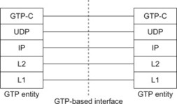
Figure 11.2.1.1 GTP Control Plane Protocol Stack.
For GTPv1-C, some example messages that carry out the functions mentioned above are provided here for the readers before delving into the protocol details.
For GTPv1-C some example message flows between SGSN and GGSN:
| Functions | Message name | Entities | Interface |
| Mobility management | SGSN context Request | SGSN-SGSN | Gn |
| Forward Relocation request | SGSN-SGSN | Gn | |
| Tunnel management | Create PDP context | SGSN -> GGSN | Gn/Gp |
| Update PDP context | SGSN -> GGSN | Gn/Gp | |
| Path management | Echo request | SGSN-GGSN | Gn/Gp |
Similar messages for EPS network are shown in detail under the interface details later on.
Example of GTPv1-U message can be described similarly, though note that the main purpose of these control messages is to ensure ‘smooth’ user data traffic handling for uplink and downlink direction for the end-user. These messages include Echo request/response for path management purposes and Error Indication messages for exception handling. A GTP entity may use the Echo request to find out if the other GTP entity is alive. The Error Indication messages can be used to inform the other GTP entity that there is no EPS bearer (or PDP context in case of GPRS) corresponding to a received user plane packet. The actual control signalling for GTP-U is performed over S1-AP (for MME and eNodeB) and GTPv2-C (for the core network entities) and over RANAP and GTPv1/v2-C for RNC and core network entities (Figure 11.2.1.2).
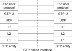
Figure 11.2.1.2 GTP-U Protocol stack.
Let us now get into a bit more detail into the GTP tunnels and their basic structure. For those readers interested in the details of the protocols such as all the messages, the coding of the parameters and the interworking of the formats themselves, we recommend the specifications where GTP-C protocols are defined in 3GPP TS 29.060, [29.060] (GTPv1) and TS 29.274, [29.274] (GTPv2-C) and GTP-U protocol is defined in 3GPP TS 29.060, [29.060] and TS 29.281, [29.281].
A few concepts must be described before one can understand the GTP protocol handling. GTP is a tunnelling protocol over UDP/IP (can be either IPv4 or IPv6). GTP is a tunnel with its specific tunnel definition and its tunnel identifiers.
GTP tunnels are used between two corresponding GTP nodes communicating over a GTP-based interface to separate traffic into different communication flows. A local Tunnel Endpoint Identifier (TEID), the IP address and the UDP port uniquely identifies a tunnel endpoint in each node, where the TEID assigned by the receiving entity must be used for the communication. Figure 11.2.2.1 illustrates an example of the GTP-C and GTP-U tunnel representation in EPS for terminals. Note that it is a simplified high level view for illustration purposes on how the GTP tunnels are represented in the system.
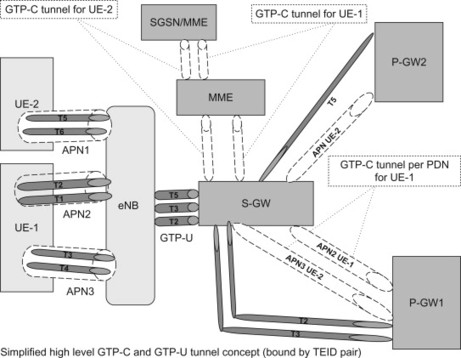
Figure 11.2.2.1 GTP Tunnel representation.
A GTP path is identified in each node with an IP address and a UDP port number. A path may be used to multiplex GTP tunnels and there may be multiple paths between two entities supporting GTP.
Another important feature of GTP protocol is its usage of Cause values in response messages. Cause values represent the actual status of the action requested (e.g. Accept/Reject) as well as additional useful information which would facilitate the receiving entity to make a more informed decision on the possible course of action. For EPS, a list of these Cause values can be found in the specification TS29.274, [29.274].
11.2.2 Control plane (GTPv2-C)
Through GTP-C messages tunnels are established, used, managed and released. A path may be maintained by keep-alive echo messages. The GTPv2-C protocol stack is shown in Figure 11.2.1.1.
For the control plane, for each endpoint of a GTP-C tunnel there is a control plane TEID (TEID-C). The scope of the GTP tunnel and the TEID-C depends on the interface and its functions (such as if the interface is used on a per terminal connection basis such as the S3 interface or per PDN connection basis like for S5/S8 interface)
-
The TEID-C is unique per PDN-Connection on GTP-based S5 and S8. The same tunnel is shared for the control messages related to all bearers associated to the PDN-Connection. A TEID-C on S5/S8 interface is released after all its associated EPS bearers are deleted.
-
There is only one pair of TEID-Cs per UE on each of the S3 and the S10 interfaces. The same tunnel is shared for the control messages related to the same UE operation. A TEID-C on S3/S10 interface is released after its associated UE context is removed or the UE is detached.
-
There is only one pair of TEID-C per UE over the S11 and the S4 interfaces. The same tunnel is shared for the control messages related to the same UE operation. A TEID-C on S11/S4 interface is released after all its associated EPS bearers are deleted.
GTP defines a set of messages between two associated EPC entities. The messages are defined in 3GPP TS 29.274, [29.274] and shown here for illustration purposes. For most detailed and up to date information, the reader should look at the latest version of the specification.
Message types for GTPv2 are listed in Table 11.2.2 below.
11.2.3 User plane (GTPv1-U)
GTP-U tunnels are used to carry encapsulated payload (original Packet Data Unit to be tunnelled) and signalling messages between a given pair of GTP-U Tunnel Endpoints. The TEID-U which is present in the GTP header indicates which tunnel a particular payload belongs to. Thus packets are multiplexed and de-multiplexed by GTP-U between a given pair of Tunnel Endpoints.
In Case of LTE/EPC, the GTP-U tunnels are established using S1-MME or GTP-C (e.g., EPS bearer establishment process) and in case of 3G packet core, it is established as mentioned before using RANAP and GTP-C (e.g., PDP context activation process). The protocol stack for GTP-U is shown in Figure 11.2.1.2.
As there exists different protocol versions, the version-not-supported indicator is used to determine what version the peer GTP endpoint supports.
11.2.4 Protocol format
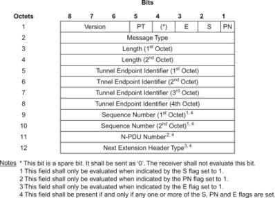
The control plane GTP uses a variable length header. Control Plane GTP header length is of a multiple of four octets as shown in the example below according to TS 29.274, [29.274]:
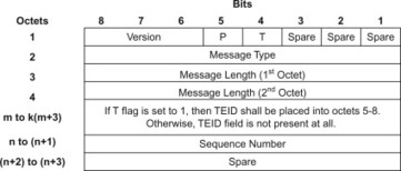
The GTP-C header may be followed by subsequent information elements dependent on the type of control plane message. The format of a GTPV2-C message is illustrated below.
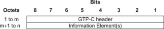
In GTPv2-C, the information elements are added for new parameters if needed in future instead of using extension headers that used to be in use for GTPv1-C.
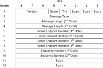
For EPS, the GTPv2-C header takes the following form (EPC functional message specific header format which does not include messages such as Echo type etc.):
Whereas a user plane GTP header would, for example, have the following format as specified in 3GPP TS 29.281, [29.281]:
11.3 Mobile IP
11.3.1 General
The basic IP stack does not provide support for mobility. If a UE has been allocated an IP address, this IP address is used not only to identify the UE in the sense that packets sent to this IP address is really destined to that UE. The IP address is also used to identify the network where the UE has attached. Each global IP address belongs to a certain IP sub-network. Routers connecting different sub-networks will, with the help of routing protocols, make sure that packets destined to this IP address will reach the sub-network to which this IP address ‘belongs’. If the UE connects to another IP sub-network the IP packets destined to the old IP address will still be routed to the old sub-network. The UE will thus no longer be reachable using the old IP address. Furthermore, even packets sent by the UE in its new sub-network may be discarded. The reason is that routers or firewalls may perform egress filtering of traffic leaving the sub-network and discard packets sent with IP addresses not belonging to the network. This has been illustrated in Figure 11.3.1.1. The change of sub-network may, for example, occur if the UE moves and connects to another network using the same interface (e.g., a UE that move between WLAN hotspots) or connects to another network using another access technology (e.g., goes from using a 3GPP access to using WLAN).
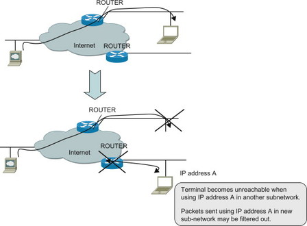
Figure 11.3.1.1 A node becomes unreachable with its original IP address when moving to another IP sub-network.
Packets destined to the UE’s old IP address will continue to end up on the old sub-network corresponding to that IP address. The UE thus needs to change IP address and get an IP address from the IP address range corresponding to the new point-of-attachment. In this way the UE will be reachable at its new point-of-attachment using its new IP address. However, if the UE replaces its old IP address with a new one, ongoing IP sessions need to be terminated and then restarted with the new IP addresses.
Mobile IP (MIP) is intended to solve these problems by providing mobility support on the IP layer. Mobile IP allows the UE to change its point-of-attachment (i.e., sub-network) while continuing to use the same IP address and maintaining ongoing IP sessions. Since Mobile IP operates on the IP layer, it can provide mobility support for different kinds of lower layers. Mobile IP is thus suitable to provide mobility not just when moving across different IP networks for the same access technology, but also across heterogeneous access technologies. How this works is explained below.
EPS makes use of Mobile IP to provide IP level mobility when the UE moves between different access technologies, for example, from an access in the 3GPP family of accesses to a WLAN access.
Mobile IP is specified by the IETF. In fact, IETF has specified different variants of Mobile IP applicable to IPv4, IPv6 or both IPv4 and IPv6. The different variants are more or less related with one another. Mobile IPv4, [3344] is applicable to IPv4 and was specified first. The Mobile IP version for IPv6, Mobile IPv6 (MIPv6), [3775], reuses many of the basic concepts developed for Mobile IPv4, but is still a distinct protocol. Dual-stack MIPv6, [5555] is based on MIPv6 and contains the necessary enhancements for dual-stack IPv4/IPv6 operation. There is also a network-based version of MIPv6 called Proxy Mobile IPv6 (PMIPv6), [5213]. Figure 11.3.1.2 illustrates the different variants and also indicates their relation. In addition, there are numerous RFCs containing amendments, optimizations and enhancements, for example, to improve handover performance (not illustrated in the figure). There have also been proposals for Proxy Mobile IPv4 and dual-stack Mobile IPv4 variants, but these are not covered here.
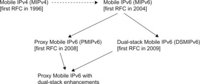
Figure 11.3.1.2 Mobile IP family tree.
The Proxy Mobile IPv6 with dual-stack enhancements was, when this book was prepared, still an Internet Draft but assumed to be soon be approved as RFCs..
It is not feasible in a book like this to describe all different variants of Mobile IP or even all aspects and details of a single Mobile IP variant. Instead we provide a high-level overview of primarily MIPv6 and dual-stack MIPv6. In Section 11.4, PMIPv6 is covered. These are the main Mobile IP-based protocols used in EPS. Also Mobile IPv4 is supported by EPS to some extent. However, we regard dual-stack MIPv6 and PMIPv6 as the more general and future proof Mobile IP protocols and also more relevant to EPS. Therefore Mobile IPv4 is only discussed briefly in this chapter, mainly pointing out the differences compared to MIPv6. The description also focuses on those aspects of MIPv6 that are most relevant for its use in EPS. A reader interested in a more complete description of all features and different options of Mobile IP in general and MIPv6 in particular should, for example, consult dedicated books on the topic or the relevant RFCs.
11.3.2 Host-based and network-based mobility mechanisms
Before going into the details on how Mobile IP works, it is useful to take a high-level view of different mobility concepts. As was described in, Section 6.4, IP level mobility protocols could be roughly classified into two basic types; host-based mobility protocols and network-based mobility protocols. Mobile IP is a host-based mobility protocol where the UE has functionality to detect movement and to exchange Mobile IP signalling with the network in order to maintain IP-level session continuity. The other type of mobility protocol, or mobility scheme, is the network-based mobility management scheme. In this case the network can provide mobility services for a UE that is not explicitly exchanging mobility signalling with the network. It is in this case a task of the network to keep track of the UE’s movements and ensure that the appropriate mobility signalling is executed in the core network in order for the UE to maintain its session while moving. PMIPv6 described in, Section 10.4 is an example of a network-based mobility protocol. GTP is another example of a network-based protocol that is used to support mobility.
11.3.3 Basic principles of mobile IP
Before going into the actual mechanisms of Mobile IP it is necessary to describe the terms and concepts used. The description in this section is to most degree covering Mobile IP concepts in general, but is geared towards MIPv6 in specific matters, dual-stack MIPv6 is covered further below. Even though EPC supports both MIPv4 (in Foreign Agent mode) and DSMIPv6 for mobility between heterogeneous accesses, DSMIPv6 is the more general and future proof protocol of the two. Mobile IPv4 in FA mode is supported primarily for interworking with legacy CDMA and WiMAX systems.
As mentioned above, Mobile IP allows a UE to be always reachable using the same IP address even when the UE moves between different IP sub-networks. This IP address is called the Home Address (HoA) and is an IP address assigned from the address space of the home network (also referred to as the home link).
Note that ‘home network’ in Mobile IP terminology is not the same as the ‘home network’ (or ‘Home PLMN’) used when discussing roaming. A home network in Mobile IP sense is the IP network where the UE’s HoA has been allocated and is thus a term related to IP topology and IP routing. The ‘home network’ in case of roaming is however a term denoting the network of the home operator or business entity where the subscriber has its subscription. The Mobile IP ‘home network’ may be located in the Home PLMN or the Visited PLMN depending on if the PDN GW is allocated from Home PLMN or Visited PLMN.
In Mobile IP terminology, the mobile UE is referred to as a Mobile Node (MN). However, in order to align with the terminology used in the rest of this book, we will continue to use the term ‘UE’ when referring to the Mobile Node also in this chapter.
When the UE is attached to its home network it can use the HoA in the usual way without any need for Mobile IP services. However, when the UE attaches to a different IP network where the HoA is not topologically located, this is no longer possible. In Mobile IP terminology, the UE is in this case attached to a ‘foreign link’ (or ‘foreign network’).
When the UE is attached in a foreign network it acquires a local IP address from that network. This IP address is in Mobile IP terminology called a Care of Address (CoA). The CoA is topologically located in the network the UE is currently accessing.
When the UE is at this foreign network, IP packets addressed to the CoA will reach the UE, while packets addressed to the HoA will reach the home network instead and not the UE. To solve this problem, Mobile IP introduces a network entity that maintains an association between the CoA and the HoA. This entity is called a Home Agent (HA) and is a router that is located on the UE’s home network. (For EPS, the HA functionality is located in the PDN GW). The association between the two IP addresses is called a binding. When the UE has attached to a foreign link it informs the HA about its current point-of-attachment (i.e., its current local IP address, the CoA). The HA then intercepts packets that are routed to the home network addressed to the HoA, and forwards them in a tunnel to the UE’s current location, that is, its CoA.
This behaviour, at least for the down-link, resembles the mail forwarding that can be used if a family moves from one city to another. The post office in the old city can be informed about the family’s new address, and will ‘intercept’ and forward all mails addressed to the old address by placing the mails in a new envelope addressed to the family’s new address. As we will see below, this comparison does however not really work when looking at up-link packets. In the Mobile IP case also up-link packets are typically sent via the HA in the home network, while in the example with the post office, the family can send letters from its new address without having to send them via the post office in its old home town. An exception to this principle is MIPv6 Route Optimization (RO) where traffic is not sent via the HA. However, since RO is not supported in EPS, this is only briefly discussed below.
Before describing in more detail how MIPv6 works, we should also introduce the third entity in the MIPv6 architecture, the Correspondent Node (CN). The CN is an IP node with which the UE is communicating. It could, for example, be a server of some kind or another UE with which the Mobile IP UE is communicating. The CN does not need any Mobile IP functionality.
The basic Mobile IP operation will be described below by going through an example use case where a binding is created and updated.
11.3.3.1 Bootstrapping
When the UE is powered on, it connects to a network and acquires an IP address from the local network. This IP address becomes the CoA. In order to utilize Mobile IP, the UE needs to have the IP address of the HA, a security association with the HA and a HoA. The process for establishing this information is called bootstrapping. Even though this information may be statically pre-configured in the UE and HA, it is in many cases beneficial to establish this information dynamically. In particular, in an EPS deployment with a large number of subscribers the option to pre-configure the UE does not scale very well and would be difficult for operators to manage. Therefore dynamic bootstrapping mechanisms are used.
The MIPv6 capable UE also needs to determine whether it needs to invoke Mobile IP or not. The UE does this by performing home link detection to determine whether it is attached to its home link or to a foreign link.
Several different methods have been defined for how the UE discovers an IP address of a suitable HA. Also EPS supports different procedures for how the HA IP address is provided to the UE. It may be discovered using DNS or be provided to the UE using other means depending on what access technology the UE is using. For more details, see Section 9.2.6.
Once the UE knows the HA IP address, it can contact the HA to set up a security association. MIPv6 uses IPSec to protect the Mobile IP signalling and IKEv2 to establish the IPSec SA. During the IKEv2 procedure, the UE and HA perform mutual authentication and the HA can also deliver the HoA to the UE. See Section 11.3.4 for further aspects related to MIPv6 security.
When the UE has acquired its HoA it performs home link detection by checking whether the HoA is ‘on-link’ or not, that is, whether or not the HoA belongs to the local network where the UE is currently attached. If the UE is attached to its home network no Mobile IP services are needed. The UE can use its HoA in the usual way.
11.3.3.2 Registration
If the UE is attached to a foreign network, the UE needs to inform the HA about the current CoA. The UE does this by sending a Mobile IP Binding Update (BU) message to the HA. The BU message contains the HoA and the CoA and is protected using the IPSec SA previously established. The HA maintains a Binding Cache containing the HoAs and CoAs for each UE that have registered with the HA. When receiving the BU for a new UE, the HA creates a new entry in the Binding Cache and replies to the UE with a Binding Acknowledgement (BA). The MIPv6 registration is illustrated in Figure 11.3.3.2.1. For a more detailed call for initial attach using DSMIPv6, see Section 12.2.4.
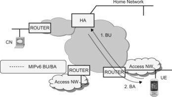
Figure 11.3.3.2.1 A node registers with the Home Agent by sending a Binding Update.
11.3.3.3 Routing of packets
When the UE is attached to a foreign network and a binding cache entry has been created in the HA, the HA intercepts all packets routed to the home network and destined to the UE’s HoA. The HA then encapsulates the packets in a new IP header and forwards the packet to the UE’s CoA. When receiving the packet, the UE de-capsulates it and processes it in the normal way. When the UE sends packets, the UE tunnels the packets to the HA which de-capsulates the packets and forwards the packets towards the final destination. This bi-directional tunnelling of packets between the UE and the HA is illustrated in Figure 11.3.3.3.1.
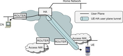
Figure 11.3.3.3.1 User plane tunnelled bi-directionally between UE and Home Agent.
An alternative to bi-directional tunnelling would have been for the UE to sent the up-link packets directly to the destination, without tunnelling them to the HA first. This would have created a ‘triangular routing’ where down-link packets are routed to the home network and passes through the HA while up-link packets are routed directly to the final destination, bypassing the HA. MIPv6 always uses bi-directional tunnelling while Mobile IPv4 allows both triangular routing and bi-directional tunnelling (called reverse tunnelling for Mobile IPv4). It can also be noted that MIPv6 allows for a feature referred to as Route Optimization where both up-link and down-link user plane is sent directly between the UE and the CN, without passing the HA. Route optimization is not used in EPS, but is briefly described in Section 11.3.7.
11.3.3.4 Binding lifetime extension
A binding in the HA has a certain lifetime. Unless the binding is renewed before the lifetime expires, the HA will remove the binding. This is used, for example, to clean up bindings belonging to terminals that are no longer attached to the network and that did not cancel the binding properly when they were disconnected. In order for the terminal to refresh the binding, the terminal sends a new BU well before the expiry of the binding lifetime.
11.3.3.5 Movement and update of the binding
In case the UE moves to different point-of-attachment and receives a new local IP address the UE again performs home link detection to determine whether it is now connected to the home link. If the UE determines that it has moved to another network different from its home network, the UE needs to inform the HA about the new CoA acquired in the new network. If not, the HA would continue forwarding the IP packets to the old foreign network. The UE thus sends a new BU to the HA containing its HoA and the new CoA. When receiving the BU, the HA updates the binding cache entry for the HoA with the new CoA and starts forwarding traffic to the new CoA. The movement, MIPv6 BU/BA signalling and the new user plane tunnel are illustrated in Figure 11.3.3.5.1.
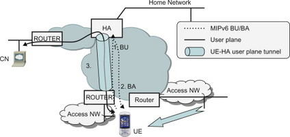
Figure 11.3.3.5.1 Movement, update of binding and switch of tunnel towards new point-of-attachment.
11.3.3.6 Movement and de-registration
If the UE moves to its home link it does not need the Mobile IP service anymore since it can use the HoA in the usual way. The UE therefore sends a BU to inform the HA that it is now on its home network and that the HA no longer needs to intercept and forward packets on behalf of the UE. The user plane tunnel between UE and HA is also removed. In EPS the UE is always considered to be on its home link when using a 3GPP access. Therefore deregistration occurs, for example, when the UE moves from a non-3GPP access where S2c is used to a 3GPP access (Figure 11.3.3.6.1).
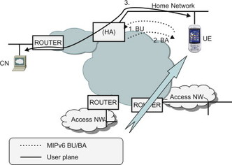
Figure 11.3.3.6.1 Return home procedure.
11.3.3.7 Binding revocation
If the UE is located on a foreign link with a binding registration in the HA, the HA may in some cases want to terminate the Mobile IP session. This may, for example, happen if the user is no longer authorized to use Mobile IP. In this case the HA can send a Binding Revocation Indication (BRI) to the UE. The UE then replies with a Binding Revocation Acknowledgement (BRA) and the Mobile IP session is terminated. The BRI and BRA messages are defined in, [draft-ietf-mext-binding-revocation].
11.3.4 Mobile IPv6 security
The Mobile IP signalling extends between the UE and the HA. It is therefore important to ensure that this signalling is properly protected. Mobile IPv4 and MIPv6 use different security solutions, and in line with the rest of this chapter we will focus on MIPv6.
Even for MIPv6 there exist different security solutions. The MIPv6 RFC requires that IPSec is used to protect the BU and BA between the UE and the HA. Originally, MIPv6 security was based on the old IPSec architecture, either using manual configuration or using IKEv1 to establish the IPSec security association (see Section 11.9 for more information on IPSec). This is described in RFC 3775, [3775] and RFC 3776, [3776]. Recently, the MIPv6 specification has been updated to support also the revised IPSec architecture and IKEv2. The usage of MIPv6 with the revised IPSec architecture is described in RFC 4877, [4877].
The UE and the HA must support the use of ESP in transport mode to protect the BU and BA messages. Integrity protection is mandatory while ciphering is optional.
In addition to the IPSec-based solutions, an alternative security mechanism has been documented in RFC 4285, [4285]. Instead of using IPSec, this security solution provides integrity protection by adding message authentication mobility options to the MIPv6 signalling. This solution was developed for use in networks based on the legacy 3GPP2 standard. The motivation was that it would be more lightweight than the IPSec-based solutions and that it would provide sufficient security in the specific 3GPP2 deployments. However, for EPS-based systems, only the IKEv2-based security solution is supported.
For more details on Mobile IP security in EPS, see the description of the S2c interface in, Section 10.5.
11.3.5 Packet format
11.3.5.1 Mobile IP signalling (control plane)
In order to understand the MIPv6 packet format, it is useful to recapture a few basic aspects about the IPv6 header. IPv6 defines a number of extension headers that can be used to carry the ‘options’ of the IP packet. The extension headers, if they are present, follow after the ‘main’ IPv6 header and before the upper layer header (e.g., TCP or UDP header). One of the extension headers, the hop-by-hop header, contains information intended for each router on the path. This header therefore has to be examined by each router on the path. In general however, the extension headers contain information only intended for the final destination of the packet. This means that these extension headers do not need to be examined by every router on the path. Examples of extension headers containing information for the final destination of the packet are the ESP header (for IPSec) and the fragmentation header (in case the packet is fragmented). The ESP and fragmentation headers are extension headers defined for explicit purposes. Another way to provide options to the final destination is to use the Destination Options extension header. This header can contain a variable number of options. Figure 11.3.5.1.1 illustrates an IPv6 packet containing ‘main’ header, extension headers and payload.
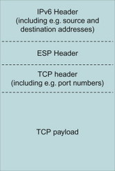
Figure 11.3.5.1.1 Example IPv6 packet containing main IPv6 header, an extension header as well as an upper layer header and payload.
MIPv6 defines a new extension header, called the Mobility Header (MH), to carry the MIPv6 messages. All messages used in MIPv6, including the BU and BA, are defined as MH types. The MH format is shown in Figure 11.3.5.1.2.
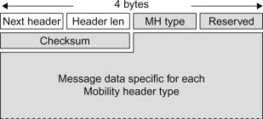
Figure 11.3.5.1.2 Mobility Header format.
The Next Header and Header Length fields are not specific to the MH but are present in all extension headers. The Next Header field indicates what type of header (e.g., extension header or upper layer header) follows this header. The Header Length field contains the length of the header. The MH type field indicates what particular MIPv6 message this is, for example, a BU, BA, BRI, Binding Error, etc. The Checksum field contains a checksum of the MH. The Message Data part contains information specific for each message (see below).
This means that MIPv6 messages are carried as part of the IPv6 header information and not as payload of the IPv6 packets. This is different from Mobile IPv4 that is carried as UDP encapsulated payload in an IPv4 packet.
MIPv6 also defines other IPv6 header fields. A new option for the Destination options header is used to carry the HoA. MIPv6 also defines a new routing header variant (Routing Header type 2) as well as a number of new ICMPv6 messages. Below we describe the BU and BA messages. It is however not the intent of this book to go through all MIPv6 messages and headers. An interested reader is referred to the MIPv6 RFC 3775, [3775] for more details.
Figure 11.3.5.1.3 illustrates the Binding Update message. It contains the main IPv6 header, the ESP header (for protecting the message), a Destinations options header carrying the Home Address as well as the Binding Update Mobility Header. The Binding Update Mobility Header is further detailed in Figure 11.3.5.1.4.
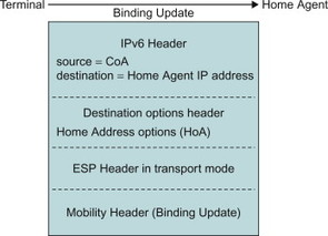
Figure 11.3.5.1.3 Binding Update message.

Figure 11.3.5.1.4 Mobility Header for the Binding Update message.
The A, H, L, K, M, R, P and F fields in the BU MH contain flags for different purposes. As we will see in Section 11.4, the P flag is used by PMIPv6. The Sequence number is used by the receiver to determine the order in which the BUs were sent by a UE. This is, for example, useful in case the UE rapidly moves between different accesses and sends multiple BUs within a short interval. The Lifetime is the time that remains before the binding expires. The Mobility options field may contain additional options. One example is the Alternate CoA mobility option. The CoA is used as source address of the BU, but including it in the CoA mobility option as well allows it to be protected by ESP (ESP in transport mode does not protect the IP header). In response to a BU, the HA sends a BA. Figure 11.3.5.1.5 illustrates the BA message. It contains the main IPv6 header, the ESP header (for protecting the message), a type 2 Routing Header carrying the HoA as well as the BA MH.
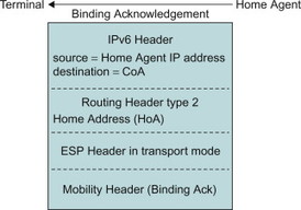
Figure 11.3.5.1.5 Binding Acknowledgement message.
The MH for the BA message is illustrated in Figure 11.3.5.1.6. The status field indicates the result of the BU. The sequence number sent in the BA is the same as that received in the BU. This allows the Mobile IP client to match Updates with Acknowledgements. The Lifetime includes the time granted by the HA until the binding expires. To maintain the binding in the HA, the UE must refresh the binding before it expires by sending a new BU message to the HA.
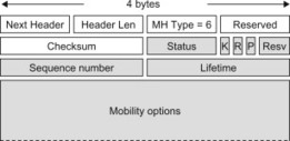
Figure 11.3.5.1.6 Mobility Header for the Binding Acknowledgement message.
11.3.5.2 User plane
When the MIPv6 session has been established, all user plane packets for the HoA are tunnelled between the UE and the HA (except in case where Route Optimization is used, see Section 11.3.7. This tunnelling is performed using IPv6 encapsulation defined in RFC 2473, [2473]. Note however that additional encapsulation protocols are defined for the dual-stack version of MIPv6.
11.3.6 Dual-stack operation
The text above has described the basics of MIPv6. MIPv6 was designed for IPv6 only and thus supports only IPv6 traffic and IPv6 capable networks. Mobile IPv4 on the other hand was designed for IPv4 and supports only IPv4 traffic and IPv4 capable networks. An IPv4-only node can thus use Mobile IPv4 to maintain connectivity while moving between IPv4 networks and an IPv6-only node can use MIPv6 to maintain connectivity while moving between IPv6 networks. However, this situation is not optimal for a dual-stack UE supporting both IPv4 and IPv6. Such a UE would need to use Mobile IPv4 for its IPv4 stack and MIPv6 for its IPv6 stack so that it can move between IPv4 and IPv6 subnets. There are a few drawbacks with this solution for dual-stack UEs. First of all it requires that the dual-stack UE needs to support two sets of mobility management protocols, which increases the complexity of the UEs. Also, it needs to send two sets of Mobile IP signalling messages on every handover, to inform both the Mobile IPv4 HA and the MIPv6 HA about the move. Furthermore, since Mobile IPv4 requires an IPv4 CoA and MIPv6 requires an IPv6 CoA, all access networks need to be dual-stack in order to provide mobility for both the IPv4 and IPv6 sessions. For example, a dual-stack UE attempting to connect via an IPv4-only network would not be able to maintain connectivity of its IPv6 applications and vice versa. Also to the operator this scenario has drawbacks since the operator needs to run and maintain two sets of mobility management systems on the same network.
The dual-stack extensions of MIPv6 avoid these drawbacks, by enhancing the protocol to support also IPv4 access network (i.e., IPv4 CoA) and IPv4 user plane traffic (i.e., using an IPv4 HoA). The dual-stack version of MIPv6 is usually referred to as DSMIPv6 and is specified in RFC 5555. The solution defines extensions for carrying the mobile node’s IPv4 CoA, IPv4 HoA and IPv4 address of the HA in the MIPv6 signalling messages. It should be noted that DSMIPv6 requires that the terminal is always assigned an IPv6 HoA.
As indicated above, DSMIPv6 supports more network scenarios than basic MIPv6. Scenarios supported by DSMIPv6 are illustrated in Figure 11.3.6.1. A requirement to support both IPv4 and IPv6 traffic is that the HA supports both IPv4 and IPv6. Even though only single-stack foreign networks are shown in the figure, the foreign network may of course support both IPv4 and IPv6. In the latter case, the terminal should prefer using an IPv6 CoA.
As explained in the previous section, all MIPv6 messages are defined as native IPv6 packets (using IPv6 extensions headers, etc.). In an IPv4-only foreign network the UE can however only acquire an IPv4 CoA and send IPv4 packets. In order to send a MIPv6 message to the HA, the MIPv6 packets must be encapsulated in IPv4 and sent to the IPv4 address of the HA. An example of a BU message for an IPv4-only foreign network is shown in Figure 11.3.6.2. In order to support private IPv4 addresses and NAT traversal, UDP encapsulation may be used.
Also additional user plane tunnelling formats are needed to support IPv4 user data and IPv4-only foreign networks. The IPv4 or IPv6 user plane data is encapsulated in either IPv4 or IPv6 depending on the IP version of the foreign network. Furthermore, in order to support private IPv4 addresses and NAT traversal, also UDP encapsulation is supported. The user data tunnelling formats for the different scenarios are shown in Figure 11.3.6.1.
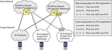
Figure 11.3.6.1 Network scenarios for dual-stack MIPv6.
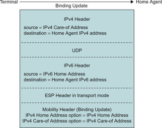
Figure 11.3.6.2 DSMIPv6 Binding Update message for an IPv4 CoA.
11.3.7 Additional MIPv6 features – route optimization
MIPv6 is a quite extensive protocol and so far we have only provided a very high level description of a few main functions. One feature that was only briefly mentioned above is Route Optimization (RO). RO is supported for MIPv6 but not available in Mobile IPv4. It is an alternative to the bi-directional tunnelling between UE and HA. With RO, the user plane traffic is sent directly between the UE and the Correspondent Node (CN) without passing the HA.
RO is not supported by EPS and there are different reasons for that. In EPS the HA is located in the PDN GW and it is always assumed that the user plane traffic goes through one PDN GW where charging, policy enforcement and lawful intercept can take place. Furthermore, MIPv6 RO is limited to IPv6 traffic and IPv6 foreign networks. RO is thus not supported for IPv4 traffic even when DSMIPv6 is used. EPS provides other solutions that can enable efficient routing. In roaming situations it is, for example, possible to assign a PDN GW located in the visited PLMN, thus avoiding the transport of all user plane traffic to the home PLMN. Also PDN GW selection functions in EPS have impact on the routing, for example, by selecting a PDN GW that is geographically close to the UE.
MIPv6 RO allows a UE to inform a CN about its current CoA. The UE basically sends a BU to the CN and the CN in turn creates a binding in between the HoA and the CoA. When the CN sends a packet to a specific IP address, it checks its bindings for an entry (i.e. a HoA) that matches the IP address. If a match is found, the CN can communicate with the UE using the CoA. Traffic sent by the CN will thus be routed to the foreign network directly without passing the home network. MIPv6 defines special messages as well as security mechanisms to set up the route binding in the CN. Considering that RO is not used in EPS, and this is a book on EPS, we will not go into further details on this topic. The interested reader is instead referred to the MIPv6 RFC 3775, [3775].
11.4 Proxy Mobile IPv6
11.4.1 General
As explained in Section 11.3, mobility schemes can often be classified as either being host-based or network-based. MIPv6, described in the previous section, is a host-based mobility management solution where the UE has functionality to detect movement and to exchange IP mobility signalling with the network in order to maintain IP-level session continuity.
PMIPv6, defined in RFC 5213, [5213], on the other hand is network-based mobility management protocol that has a similar purpose as MIPv6, that is, to facilitate IP-level session continuity. PMIPv6 reuses much of the concepts and packet formats that have been defined for MIPv6. A key difference between MIPv6 and PMIPv6 is however that with PMIPv6 the UE does not have Mobile IP software and does not participate in the IP mobility signalling. A key intent of PMIPv6 is in fact to enable IP-level mobility also for those UEs that do not have Mobile IP client functionality. Instead it is mobility agents in the network that track the UE’s movement and perform IP mobility signalling on behalf of the UE. A mobility agent in the network acts as a proxy for the UE when it comes to IP mobility signalling, hence the name Proxy Mobile IPv6.
Since PMIPv6 reuses many parts of MIPv6 such as packet format, the description of PMIPv6 in this section will to a large extent build on the description of Mobile IP in Section 11.3.
PMIPv6 is used on the S2a, S2b interfaces and as a protocol alternative on the S5/S8 interface. Specific aspects related to PMIPv6 usages in EPS are described in previous chapters, for example, regarding EPS bearers [, Section 6.3], mobility [, Section 6.4], PCC [, Section 8.2], and so on. For more details on the PMIP-based interfaces, see Section 10.4. Below we describe the PMIPv6 protocol as such.
11.4.2 Basic principles
PMIPv6 introduces two new network entities; the Mobile Access Gateway (MAG) and the Local Mobility Anchor (LMA). The MAG is the mobility agent that acts essentially as the Mobile IP client on behalf of the UE. The LMA is the mobility anchor point and its role is similar to that of the HA for MIPv6, that is, to maintain a binding between the HoA of the UE and its current point-of-attachment. The MAG is located in the access network while the LMA is located in the network where the HoA is topologically located. The PMIPv6 architecture is illustrated in Figure 11.4.2.1.
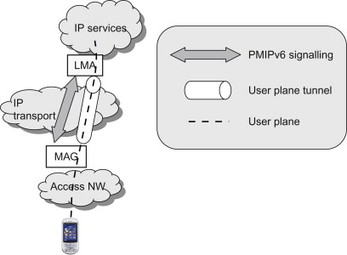
Figure 11.4.2.1 Proxy Mobile IP.
The responsibility of the MAG is to detect the movement of a UE and to initiate the appropriate IP mobility signalling. A key function of the MAG is also to emulate the UE’s home network, that is, to make sure that the UE does not detect any change in its layer-3 attachment even after the UE has changed its point-of-attachment. The UE shall be allocated the same IP address and other IP configuration parameters after the move as it had before the move. Furthermore, the target MAG is also updated with other parameters such as IPv6 link-local address to be used by the MAG. This is to ensure that, in a handover, the target MAG uses the same link-local address as the source MAG. This gives the UE the impression that it is still on the same local network even after the handover. How this works we will see in an example scenario below.
Below we provide an example for how PMIPv6 works and can be used in a network.
When the UE connects to an access network it typically performs access authentication and authorization for that access. During the access authentication, the UE also provides the user identity (the IMSI in case of EPS) and the security (e.g., encryption) may be set up. When the UE has successfully attached to the access network and provided its identity, it may, for example, request an IP address using DHCP. It should be noted that the details regarding the signalling between UE and the MAG depends very much on the type of access used. For example, access authentication and IP address allocation may be done in different ways in different access systems. Please see Chapter 7 and Section 6.3 for further details on access-specific aspects.
The MAG in the access network now initiates PMIPv6 signalling towards the LMA to inform the LMA of this user’s current point-of-attachment. To do this the MAG first has to select a suitable LMA (this is similar to how the UE must discover a suitable HA in case of Mobile IP). When PMIPv6 is used in EPS, the MAG performs LMA discover by resolving the APN using the DNS functions (for more details, see Chapter 9). The PMIPv6 RFC 5213, [5213] also describes other means for the MAG to find a suitable LMA.
Once an LMA has been selected, the MAG sends a Proxy Binding Update (PBU) message to the LMA. The PBU contains the Proxy CoA which is the IP address of the MAG. This allows the LMA to create an association (binding) between the Proxy CoA and the UE’s HoA in a much similar way as the MIPv6 HA creates a binding between the CoA and the HoA. The difference here is that with PMIPv6 the UE is not aware of the Proxy CoA.
The LMA then replies with a Proxy Binding Acknowledgement (PBA). This message contains the IPv6 prefix allocated to the terminal. (With the dual-stack amendments described further below, the PBA may also contain an IPv4 address allocated to the terminal). The PBA also carries other IP parameters associated with the home network such as the MAG IPv6 link-local address. Once the MAG receives the PBA it can provide the allocated IP address/prefix to the UE (e.g., using DHCP).
When this is done, the MAG and LMA establish a tunnel where the user plane for the UE is forwarded. All user plane data sent by the UE is intercepted by the MAG and forwarded to the LMA via the MAG-LMA tunnel. The LMA in turn de-capsulates the packets and forwards them towards their final destination. In the other direction, all traffic addressed to the HoA is intercepted by the LMA in the home network and forwarded to the MAG (via the tunnel) which in turn sends it to the UE (Figure 11.4.2.2).
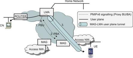
Figure 11.4.2.2 UE connected to a network using PMIPv6.
To the UE it looks like it was really connected to its home network since it is allocated the same IP address (the HoA) and other IP parameters associated with the home network. The MAG is emulating the home link towards the UE and the UE can continue its IP sessions as if it was still connected to the home network. See Section 12.2.2 for a more detailed call flow for an attach procedure using PMIP.
If the UE now moves and connects to a different access network, either using the same access technology or a different access technology, the access attach procedure will again be performed. The MAG in the new access network will detect that the UE has attached. In order to provide session continuity, the new MAG has to send a PBU to update the binding in the LMA. The new MAG therefore sends the PBU to the same LMA informing about the Proxy CoA of the new MAG. The LMA updates its binding and replies with a PBA containing, for example, the HoA and other parameters. The new MAG now assigns the same IP address (i.e., the HoA) as in the old access. The user plane tunnel is moved to the new MAG. The UE again thinks it is connected to the home network and can thus continue to use the HoA as before the change in point-of-attachment (Figure 11.4.2.3).
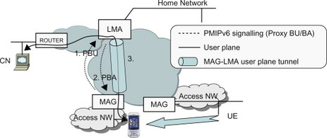
Figure 11.4.2.3 PMIP-based handover.
For a more detailed call flow of a PMIP-based handover procedure in EPS, please see Section 12.4.3.
If the LMA for some reason wants to disconnect the terminal, it sends a Binding Revocation Indication (BRI) to the MAG. The MAG in turn removes its mobility context, disconnects the terminal, and sends a Binding Revocation Acknowledgement (BRA) to the LMA. The format of the BRI and BRA messages are the same for both MIPv6 and PMIPv6, [draft-ietf-mext-binding-revocation].
One important aspect to note in the example above is that the signalling between UE and MAG is access specific. There is no IP level mobility signalling between the UE and the network as was the case for MIPv6. PMIPv6 is used inside the network in order to establish, to modify or to remove the mobility session and to provide the MAG in the access network with the home network information (e.g., HoA). In this way the MAG can emulate the home network by assigning the same IP-layer parameters as they would have been assigned in the home network. The UE is thus unaware of the topology of the network. The user plane tunnel between MAG and LMA enables the UE to use the HoA from any access link where PMIPv6 is used.
11.4.3 PMIPv6 security
Since PMIPv6 is a network-based mobility protocol it has different security requirements than MIPv6 which is a host-based mobility protocol.
PMIPv6 performs mobility signalling on behalf of a UE that has attached to its network. PMIPv6 therefore requires that proper access authentication and authorization have been performed so that there is a trusted connection between the UE and the MAG before the MAG initiates PMIPv6 signalling. If this trusted connection is not required, a malicious UE might, for example, trigger a MAG to perform mobility signalling on another user’s behalf. See Chapter 7 for further details on access security.
Also the PMIPv6 signalling itself needs to be properly protected. The PMIPv6 RFC supports protection of the PMIPv6 signalling between the MAG and the LMA using IPSec (ESP in transport mode with integrity protection). It is also possible to use other security mechanisms depending on deployment. In EPS, the Network Domain Security (NDS/IP) is the general framework for protecting signalling messages between network nodes. It is used also for PMIPv6 signalling in EPS. For further details, see the brief description of NDS/IP in, Section 7.4.
11.4.4 PMIPv6 packet format
As already mentioned, PMIPv6 inherits many concepts from MIPv6, including the packet format. The format of the PBU and PBA messages are the same as the MIPv6 BU and BA messages with the difference that the P flag has been introduced to indicate that the BU/BA refers to a proxy registration. For details regarding the format of the BU and BA messages, see Section 11.3.5. PMIPv6 also introduces new Mobility Options for use with the PBU and PBA messages. See RFC 5213, [5213] for further details.
The user plane is sent between MAG and LMA in a bi-directional tunnel. The tunnels may be unique per UE or shared by multiple UEs depending on deployment. The tunnels may be statically configured at the MAGs and LMAs in the network or be dynamically established and torn down. The MAG and LMA may use IPv6 encapsulation, [RFC 2473] for this tunnel but also GRE tunnelling is supported, [draft-ietf-netlmm-grekey-option]. EPS requires that GRE tunnelling is used where the GRE key field is used to uniquely identify a specific PDN connection, see Section 11.6.
In some environments there is a need to include specific information elements not defined as part of the main PMIPv6 specifications in the PMIPv6 messages. In this case it is possible to use vendor-specific Mobility Options that can be included with the Mobility Header. The general format of these vendor-specific options is defined in RFC 5094, [5094]. 3GPP EPS makes use of such vendor-specific options to transport, for example, the Protocol Configuration Options (PCO) fields, Charging ID and 3GPP-specific error codes, as defined in TS 29.275, [29.275].
11.4.5 Dual-stack operation
The dual-stack enhancements for PMIPv6 reuses the dual-stack features defined for DSMIPv6. This means that the PBU and PBA may contain IPv4 CoA options and IPv4 HoA options. This allows PMIPv6 to support also IPv4-only access networks as well as IPv4 HoAs. A key difference compared to DSMIPv6 is however that with PMIPv6 the IPv6 HoA is not mandatory. It is allowed to assign only an IPv4 HoA to the terminal. The dual-stack extensions for PMIPv6 are defined in, [draft-ietf-netlmm-pmip6-ipv4-support]. (Note that when this book was prepared, the dual-stack extensions for PMIPv6 was still an Internet Draft but soon to reach RFC status. Please refer to the references section for further details.) In a similar way as for DSMIPv6, when PMIPv6 is used over an IPv4 transport network, the PMIPv6 signalling messages are encapsulated in IPv4 packets. The user plane tunnel MAG and LMA are either encapsulated in IPv6, IPv4, UDP-over-IPv4 or GRE-over-IPv4/IPv6, depending on network scenario. As mentioned above, EPS uses GRE tunnelling over IPv4 or IPv6 transport. Dual-stack scenarios for PMIPv6 are illustrated in Figure 11.4.5.1. Note that the access network may be supporting IPv6 only (for simplicity this is not shown in the figure).
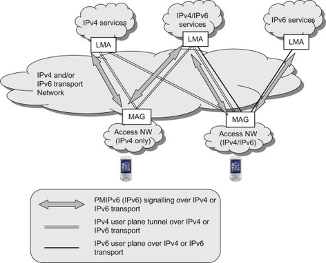
Figure 11.4.5.1 Example scenarios for dual-stack PMIPv6.
11.5 Diameter
11.5.1 Background
Diameter is a protocol originally designed for Authentication, Authorization and Accounting (AAA) purposes. It is an evolution of its predecessor, the RADIUS protocol. The Diameter protocol name is ‘derived’ from RADIUS in the sense that the diameter is twice the radius. The RADIUS protocol has been commonly and successfully deployed to provide AAA services for fixed dial-up accesses as well as for cellular CDMA systems. It is also used in GPRS networks on the Gi interface.
The Diameter protocol was designed to overcome several shortcomings of RADIUS. For example, Diameter supports improved failure handling, more reliable message delivery, bigger size information elements, improved security, better possibilities for extensibility, more flexible discovery of other Diameter nodes, etc. Furthermore, in contrast to RADIUS, Diameter provides a full specification of intermediate entities such as proxies. At the same time Diameter was constructed to provide an easy migration and compatibility with RADIUS. For example, a Diameter message, like a RADIUS message, conveys a collection of Attribute Value Pairs (AVP).
3GPP makes extensive use of Diameter on numerous interfaces. It should however be noted that 3GPP basically only uses RADIUS on the Gi/SGi interface and does, therefore, not have a significant legacy of RADIUS usage. Instead Diameter is used exclusively on several interfaces, without a RADIUS legacy. Nevertheless, comparisons between Diameter and RADIUS may be useful for readers more familiar with the RADIUS protocol. Such comparisons have therefore been included below where applicable.
11.5.2 Protocol structure
The Diameter protocol is constructed as a base standard and additional extensions called applications. The core of the Diameter protocol is defined in the Diameter base standard, RFC 3588, [3588]. This RFC specifies the minimum requirements for a Diameter implementation and includes a few general Diameter messages (called Commands in Diameter) as well as AVPs that can be carried by the commands. Extensions (called Applications in Diameter) are then created on top of the Diameter base protocol to support specific requirements. The applications may define new commands as well as new AVPs as needed. A Diameter application is thus not a program or application in the usual sense, but a protocol based on Diameter. The applications benefit from the general capabilities of the Diameter base protocol. Applications may also be based on existing, already defined, applications. In this case they inherit Diameter commands and mandatory AVPs from the application(s) they are based on, but they use new application identifiers, add new AVPs and modify the protocol state machines according to their own procedures. Figure 11.5.2.1 illustrates the protocol structure of Diameter including a few example Diameter applications.
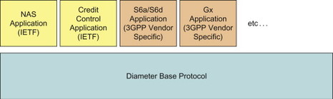
Figure 11.5.2.1 Structure of the Diameter protocol, consisting of a base protocol and extensions called applications.
Several Diameter applications have been standardized by IETF but it is also possible to define vendor-specific applications. A ‘vendor’ in this context it not necessarily a vendor making products, it is instead someone (e.g., an organization or company) that has requested a Diameter application identifier from the Internet Assigned Numbers Authority (IANA). As will be seen in the interfaces section, 3GPP has defined several vendor-specific Diameter applications that are used over the Diameter-based interfaces such as S6a, S6b, SWa, SWx and so on.In many cases the 3GPP vendor-specific applications are based on existing Diameter applications defined by IETF. Several of these applications were discussed together with the corresponding interfaces in Chapter 10.
11.5.3 Diameter nodes
The network entities implementing Diameter act in a certain role in the network architecture. Diameter defines three types of Diameter nodes depending on the role the node plays: client, server and agent. The role a certain Diameter node plays depends on the network architecture.
The client is typically the entity requesting a service from a Diameter server and thus originates the request to initiate a Diameter session with a server.
Diameter agents are Diameter nodes that can bring flexibility into the network architecture. They can be used to support a system where different parts of the network are operated by different administrations, such as in a roaming scenario. They are also used in the routing of Diameter messages to aggregate Diameter requests destined to a specific realm. The agents examine the received requests and determine the right target. This can provide load balancing features and simplified network configurations. Certain agents can also perform additional message processing.
There are four types of agents: relay, proxy, redirect and translation agents. This can be compared to RADIUS where basically only a single type of intermediary node, the RADIUS proxy, exists.
A relay agent is used to forward a message to the appropriate destination, depending on the information contained in the message. More information on Diameter message routing is provided below. The relay agent needs to understand the Diameter base protocol but need not understand the Diameter application used.
A proxy agent is similar to a relay agent, with the difference that it can perform additional processing of the Diameter messages, for example, to implement certain policy rules. Since the proxy agent can modify messages it needs to understand the service being offered and thus also understand the Diameter application being used.
A redirect agent also provides a routing function, for example, to perform realm to server resolution. The redirect agent does, however, not forward a received message towards the destination, but rather replies with another message to the node that sent the request. This reply contains information that allows the node to send the request again, but now directly to the server. The redirect agent is thus not on the routing path of the Diameter messages.
A translation agent may perform translation between Diameter and other protocols. A typical example that could be used to support migration scenarios is a translation agent translating between Diameter and RADIUS.
11.5.4 Diameter sessions, connections and transport
Diameter uses either the Transmission Control Protocol (TCP) or Stream Control Transport Protocol (SCTP) to transport the messages between two Diameter peers. Since TCP and SCTP are both connection oriented protocols, a connection between the two peers has to be established before any Diameter command can be sent. Both TCP and SCTP provide a reliable transport. This can be compared to RADIUS which uses UDP as transport protocol, which provides a connection-less and unreliable transport. For more details on SCTP and the differences compared to TCP, please see Section 11.11.
The Diameter connection between two peers should be distinguished from the Diameter session being established between a client and a server. While a connection is a transport level connection between two peers, the Diameter session is a logical concept describing the application level association between a client and server (possible spanning Diameter agents) identified by a session identifier. The Diameter peer connection and Diameter session are illustrated in Figure 11.5.4.1.
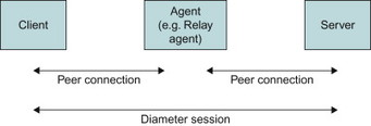
Figure 11.5.4.1 Diameter connections and Diameter sessions.
Diameter messages are protected using Transport Layer Security (TLS) or IPSec. The Diameter base specification mandates that all Diameter nodes must support IPSec while TLS is optional to support in the Diameter client. This protection is provided hop-by-hop between the Diameter peers.
In a 3GPP environment however, the general framework of NDS/IP is used for all IP-based control signalling, including Diameter. There is thus no need to provide a specific security association between the Diameter nodes in EPS. For more details on NDS/IP, please see Chapter 7.
In order to handle the flexibility of Diameter in terms of applications, security features, etc, in a dynamic fashion, two Diameter peers establishing a connection also performs a capability exchange. This exchange allows each peer to learn about the other peer’s identity and its capabilities (protocol version number, supported Diameter applications, supported vendor-specific attributes, security mechanisms, etc.).
11.5.5 Diameter request routing
As mentioned above, Diameter agents may assist in the routing of a Diameter command towards its final destination, the Diameter server.
A Diameter agent forwarding a command typically performs the routing based on the destination realm as well as the application used. It may thus use a different destination based on the application identification. The Diameter node maintains a list of supported realms and known Diameter peers as well as the peer’s capabilities (e.g., supported applications).
An agent can perform realm to server resolution and can thus be used to aggregate requests from different sources destined to a specific destination realm. This allows the agent to act as a centralized routing entity.
This feature can also be utilized in EPS in case a network deploys multiple Diameter servers, for example, multiple HSS or PCRF nodes. For the HSS, the Diameter client may not know which HSS node that handles the subscription record for a specific user. In this case a Diameter redirect agent or proxy agent can perform the resolution from a realm and user name into a server name for the HSS holding the subscription record. Diameter agents also have a specific usage for PCRF selection as is further described in Chapter 9.
11.5.6 Peer discovery
Each Diameter entity must be able to find the next hop Diameter node. With RADIUS, each RADIUS client/proxy has to be statically configured with information about the RADIUS servers/proxies with which it may need to communicate. This could cause a high burden on the network management system to keep these configurations up to date. Diameter still supports the option to statically configure Diameter peers, but in addition it is possible to use more dynamic peer discovery mechanisms, for example, by utilizing the DNS.
Diameter clients can then depend on the realm info together with the desired Diameter application and security level to look up suitable first-hop Diameter nodes to which they can forward Diameter messages. The discovered peer location as well as routing configuration will be stored locally and used when making routing decisions.
The Diameter base protocol also includes mechanisms to support transport failure handling between peers, for example, using watchdog messages to detect transport failures as well as peer failover/fallback mechanisms.
11.5.7 Diameter message format
The Diameter messages are called commands. The content of the Diameter commands consists of a Diameter header followed by a number of AVPs. The Diameter header contains a unique command code that identifies the command and consequently the intention of the message. The actual data is carried by the AVPs contained in the message. The Diameter base protocol defines a set of commands and AVPs but a Diameter application can define new commands and/or new AVPs. The base protocol, for example, defines a set of base AVP formats that can be reused, essentially in an object oriented fashion, when defining new AVPs. In an application it is thus possible not only to define new AVPs but also new commands which makes Diameter very extensible and allows the construction of applications to suit the needs of 3GPP. The Diameter message format is shown in Figure 11.5.7.1.
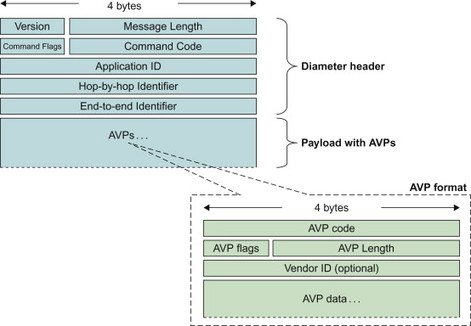
Figure 11.5.7.1 Diameter message format.
The Application ID identifies for which Diameter application the message is for. The hop-by-hop identifier is used for matching requests with responses. The end-to-end identifier is used to detect duplicate messages. Each AVP is identified using a unique AVP code. If the AVP is vendor specific, also the Vendor ID is used to uniquely identify the AVP. For more detailed information on the Diameter header and basic AVP formats, please see RFC 3588, [3588].
11.6 Generic Routing Encapsulation
11.6.1 Background
The GRE is a protocol designed for performing tunnelling of a network layer protocol over another network layer protocol. It is generic in the sense that it provides encapsulation of one arbitrary network layer protocol (e.g., IP or MPLS) over another arbitrary network layer protocol. This is different from many other tunnelling mechanisms where one or both of the protocols are specific, such as IPv4-in-IPv4, [2003] or Generic Packet Tunnelling over IPv6, [2473].
GRE is used for many different applications and in many different network deployments also outside the telecommunications area. It is not the intent of this book to discuss aspects for all those scenarios. Instead we focus on the properties of GRE that are most relevant to EPS.
11.6.2 Basic protocol aspects
The basic operation of a tunnelling protocol is that one network protocol, which we call the payload protocol, is encapsulated in another delivery protocol. It can be noted that encapsulation is a key component of any protocol stack where an upper layer protocol is encapsulated in a lower layer protocol. This aspect of encapsulation should however not be considered as tunnelling. When tunnelling is used, it is often the case that a layer-3 protocol such as IP is encapsulated in a different layer-3 protocol or another instance of the same protocol. The resulting protocol stack may look like in Figure 11.6.2.1.
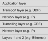
Figure 11.6.2.1 Example of protocol stack when GRE tunnelling is used.
We use the following terminology:
-
Payload packet and payload protocol: The packet and protocol that needs to be encapsulated. (The three top most boxes in the protocol stack in Figure 11.6.2.1.)
-
Encapsulation (or tunnel) protocol: The protocol used to encapsulate the payload packet, that is, GRE. (The third box from below in Figure 11.6.2.1.)
-
Delivery protocol: the protocol used to deliver the encapsulated packet to the tunnel endpoint. (The second box from below in Figure 11.6.2.1.)
The basic operation of GRE is that a packet of protocol A (the payload protocol) that is to be tunnelled to a destination is first encapsulated in a GRE packet (the tunnelling protocol). The GRE packet is then encapsulated in another protocol B(the delivery protocol) and sent to the destination over a transport network of the delivery protocol. The receiver then de-capsulates the packet and restores the original payload packet of protocol type A. Figure 11.6.2.2 shows an example of tunnelling an IPv6 packet in a GRE tunnel over an IPv4 delivery protocol.
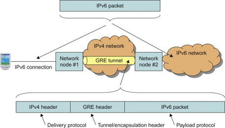
Figure 11.6.2.2 Example of GRE tunnel between two network nodes with IPv4 delivery protocol and IPv6 payload protocol.
GRE is specified in RFC 2784, [2784]. There are also additional RFCs that describe how GRE is used in particular environments or with specific payload and/or delivery protocols. One extension to the basic GRE specification which is of particular importance for EPS is the GRE Key field extension specified by RFC 2890, [2890]. The Key field extension is further described as part of the packet format below.
11.6.3 GRE packet format
The GRE header format is illustrated in Figure 11.6.3.1.
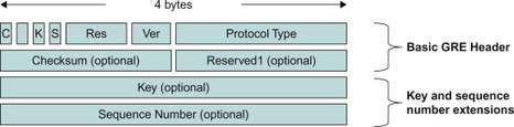
Figure 11.6.3.1 GRE header format including the basic header (RFC 2784) as well as the key and sequence number extensions (RFC 2890).
The C flag indicates whether or not the Checksum and Reserved1 fields are present. If the C flag is set, the Checksum and Reserved1 fields are present. In this case the Checksum contains a checksum of the GRE header as well as the payload packet. The Reserved1 field, if present, is set to all zeroes. If the C flag is not set, the Checksum and Reserved1 fields are not present in the header.
The K and S flags, respectively, indicate whether or not the Key and/or Sequence number is present.
The Protocol Type field contains the protocol type of the payload packet. This allows the receiving endpoint to identify protocol type of the de-capsulated packet.
The intention of the Key field is to identify an individual traffic flow within a GRE tunnel. GRE does in itself not specify how the two endpoints establish which Key field(s) to use. This is left to implementations or is specified by other standards making use of GRE. The Key field could, for example, be statically configured in the two endpoints, or be dynamically established using some signalling protocol between the endpoints. One specific usage of the Key field in EPS occurs when GRE is used as tunnel format for the PMIP-based interfaces. The Key field is here dynamically established as part of the PMIP signalling and used to identify a particular PDN connection between the MAG and LMA (see also description of PMIP in Section 11.4).
The Sequence number field is used to maintain the sequence of packets within the GRE tunnel. The node that performs the encapsulation inserts the Sequence number and the receiver uses it to determine the order in which the packets were sent.
11.7 S1-AP
In contrast to many of the other protocols in EPS, the S1-AP protocol is designed for a single interface, namely the MME to eNodeB interface. The protocol is named after the interface name (S1) and the addition of AP (Application Part) which is the 3GPP term for signalling protocol between two nodes.
S1-AP supports all mechanisms necessary for the procedures between MME and eNodeB and it also supports transparent transport for procedures that are executed between the MME and the UE.
S1-AP consists of Elementary Procedures. An Elementary Procedure is a unit of interaction between the eNodeBs and the MME. These Elementary Procedures are defined separately and are intended to be used to build up complete sequences in a flexible manner. The Elementary Procedures may be invoked independently of each other as stand alone procedures, which can be active in parallel. In some cases the independence between some Elementary Procedures is restricted, in this case the particular restriction is specified in the S1-AP protocol specification TS 36.413, [36.413]. An Elementary Procedure consists of an initiating message and possibly a response message.
The S1-AP protocol supports the following functions:
-
Setup, modification and release of E-RABs.
-
Establishment of an initial S1 UE context in the eNodeB (to setup the default IP connectivity, to setup one or more E-RAB(s) if requested by the MME, and to transfer NAS signalling-related information to the eNodeB if needed.)
-
Provide the UE capability info to MME (when received from the UE).
-
Mobility functions for UEs in order to enable intra and inter RAT HO.
-
Paging: This functionality provides the EPC the capability to page the UE.
-
S1 interface management functions, for example, Reset, Error Indication, Overload indication, Load balancing and S1 Setup functionality for initial S1 interface setup.
-
NAS signalling transport function between the UE and the MME:
-
S1 UE context Release
-
UE context modification function.
-
-
Status transfer functionality (transfers PDCP SN status information from source eNodeB to target eNodeB in support of in-sequence delivery and duplication avoidance for intra LTE handover).
-
Trace of active UE’s.
-
Location reporting.
-
S1 CDMA tunnelling (to carry CDMA signalling between UE and CDMA RAT over the S1 interface).
-
Warning message transmission.
There is no version negotiation in S1-AP and the forwards and backwards compatibility of the protocol is instead ensured by a mechanism where all current and future messages, and IEs or groups of related IEs, include ID and criticality fields that are coded in a standard format that will not be changed in the future. These parts can always be decoded regardless of the standard version.
S1-AP relies on a reliable transport mechanism and is designed to run on top of SCTP.
11.8 Non-access Stratum (NAS)
NAS denotes the protocols between the UE and the MME, which implements the mobility management and session management procedures. The NAS protocols, EPS Mobility management (EMM) and EPS Session Management (ESM), are tailor-made for E-UTRAN access and defined by 3GPP in TS 24.301, [24.301].
The EPS NAS protocols are defined as new protocols but they have many similarities with the NAS protocols used for 2G/3G. The EMM procedures are used to support UE mobility, security and signalling connection management services for ESM. The ESM procedures are used to activate, deactivate or modify EPS bearers.
11.8.1 EPS mobility management
The EMM procedures are used to keep track of the UE, to authenticate the UE, to provide security keys and to control integrity protection and ciphering. The network can assign new temporary identities and also request the identity information from the UE. In addition the EMM procedures provide the UE capability information to the network and the network may also inform the UE of information regarding specific services in the network. The EMM procedures are:
-
Attach
-
Detach
-
Tracking area update
-
GUTI reallocation
-
Authentication
-
Security mode control
-
Identification
-
MM information
-
NAS message transport (used for SMS to CS fallback enabled UE).
An optimization compared to 2G/3G is that the attach procedure is always combined with an ESM procedure that activates a default bearer. This means that the UE will receive at least one bearer to a PDN by the completion of the combined procedure.
EMM procedures can only be performed if a NAS signalling connection has been established between the UE and the network. If there is no active signalling connection the EMM layer has to initiate the establishment of a NAS signalling connection. The NAS signalling connection is established by a service request procedure from the UE. For down-link NAS signalling the MME first initiates a paging procedure which triggers the UE to execute the service request procedure. The connection management procedures rely on services from the underlying S1-AP protocol on the S1-MME interface and RRC on the E-UTRAN-Uu interface to establish connectivity.
11.8.2 EPS session management
The ESM procedures are used to manage the bearers and PDN connections for a UE. This includes procedures for default and dedicated bearer establishment, bearer modification and deactivation. As noted above the default bearer establishment is always combined with the attach procedure but it can be used as stand alone procedures to establish additional default or dedicated bearers. The ESM procedures used for E-UTRAN are in principle network-initiated but the UE may also request the network to modify the bearer resource or ask the network to execute the EPS bearer activation and deactivation procedures.
ESM procedures are:
-
Default EPS bearer context activation procedure
-
Dedicated EPS bearer context activation procedure
-
EPS bearer context modification procedure
-
EPS bearer context deactivation procedure
-
UE requested PDN connectivity procedure
-
UE requested PDN disconnect procedure
-
UE requested bearer resource modification procedure.
The NAS protocol is implemented as standard 3GPP L3 messages according to 3GPP TS 24.007, [24.007]. Standard L3 according to 24.007 and its predecessors have been used for NAS signalling messages in GSM and WCDMA/HSPA. The encoding rules have been developed to optimize the message size over the air interface and to allow extensibility and backwards compatibility without the need for version negotiation.
11.8.3 Message structure
Each NAS message contains a Protocol Discriminator and a Message Identity. The Protocol Discriminator is a 4-bit value that indicates the protocol being used, that is, for EPS NAS messages either EMM or ESM. The Message Identity indicates the specific message that is sent.
EMM messages also contain a security header that indicates if message is integrity protected and/or ciphered. ESM messages on the other hand contain an EPS Bearer Identity and a Procedure Transaction Identity. The EPS Bearer Identity indicates the assigned bearer identity and the Protocol Transaction Identifier indicates a particular NAS message exchange between the UE and the MME.
The rest of the information elements in the EMM and ESM NAS messages are tailored for each specific NAS message.
The organization of a normal EMM NAS message is shown below. Each row corresponds to one octet and bit 8 is the most significant bit in the octet.
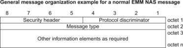
The EMM Service Request message is an exception that breaks the normal rules since it has been tweaked to fit into a single initial RRC message and hence optimizing the performance of the system. The structure of an EMM service request message is shown below.
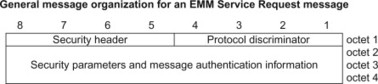
The structure of ESM messages is shown below.
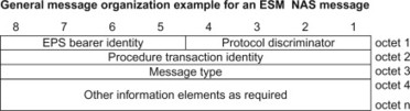
11.8.4 Security-protected NAS messages
When a NAS message is security protected the normal EMM and ESM messages above can be ciphered and/or integrity protected and encapsulated as shown below.
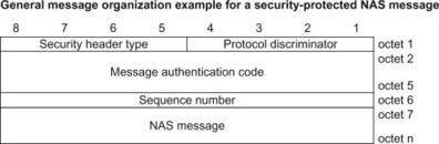
Note that the service request message is handled as a special case and is never sent as a security-protected NAS message.
Further details on the EPS NAS messages and the information elements are available in 3GPP TS 24.301, [24.301] and 24.007, [24.007].
11.8.5 Message transport
The NAS messages are transported by S1-AP between MME and eNodeB and by RRC between eNodeB and UE. The underlying protocols S1-AP (MME-eNodeB) and RRC (eNodeB-UE) provide a reliable transport for NAS messages as long as the UE remains within a cell. The NAS protocol includes reliability mechanisms to cater for event like mobility and loss of coverage.
11.8.6 Future extensions and backward compatibility
The UE and network are in principle specified to ignore information elements that they do not understand. It is hence possible for a later release of the system to add new information elements in the NAS signalling without impacting the UEs and network that implement earlier releases of the specifications.
11.9 IP Security
11.9.1 Introduction
IPSec is a very wide topic and many books have been written on this subject. It is not the intent and ambition of this chapter to provide a complete overview and tutorial on IPSec. Instead we will give a high-level introduction to the basic concepts of IPSec focusing on the parts of IPSec being used in EPS.
IPSec provides security services for both IPv4 and IPv6. It operates at the IP layer and offers protection of traffic running above the IP layer and it can also be used to protect the IP header information on the IP layer. EPS uses IPSec to secure communication on several interfaces, in some cases between nodes in the core network and in other cases between the UE and the core network. For example, IPSec is used to protect traffic in the core network as part of the NDS/IP framework, see Section 7.4. IPSec is also used on the SWu interface to protect user plane traffic between the UE and the ePDG, as well on the S2c interface to protect DSMIPv6 signalling between the UE and the PDN GW. For more details on SWu and S2c, see Sections 10.5 and 10.6.
In the next section we give an overview of basic IPSec concepts. We then discuss the IPSec protocols for protecting user data; the ESP and the AH. After that we discuss the Internet Key Exchange (IKE) protocol used for authentication and establishing IPSec Security Associations (SA). Finally we briefly discuss the IKEv2 Mobility and Multi-homing Protocol (MOBIKE).
11.9.1.1 IPSec overview
The IPSec security architecture is defined in RFC 4301, [4301]. RFC 4301 is an update of the previous IPSec security architecture specification found in RFC 2401, [2401]. The set of security services provided by IPSec include:
-
Access control
-
Data origin authentication
-
Connectionless integrity
-
Detection and rejection of replays
-
Confidentiality
-
Limited traffic flow confidentiality.
By access control we mean the service to prevent unauthorized use of a resource such as a particular server or a particular network. The data origin authentication service allows the receiver of the data to verify the identity of the claimed sender of the data. Connection-less integrity is the service that ensures that a receiver can detect if the received data has been modified on the path from the sender. It does, however, not detect if the packets have been duplicated (replayed) or re-ordered. Data origin authentication and connection-less integrity are typically used together. Detection and rejection of replays is a form of partial sequence integrity, where the receiver can detect if a packet has been duplicated. Confidentiality is the service that protects the traffic to be read by unauthorized parties. The mechanism to achieve confidentiality with IPSec is encryption, where the content of the IP packets are transformed using an encryption algorithm so that it becomes unintelligible. Limited traffic flow confidentiality is a service whereby IPSec can be used to protect some information about the characteristics of the traffic flow, for example, source and destination addresses, message length or frequency of packet lengths.
In order to use the IPSec services between two nodes, the nodes use certain security parameters that define the communication such as keys, the encryption algorithms and so on. In order to manage these parameters, IPSec uses Security Associations (SAs). An SA is the relation between the two entities defining how they are going to communicate using IPSec. An SA is uni-directional, so to provide IPSec protection of bi-directional traffic a pair of SAs is needed, one in each direction. Each IPSec SA is uniquely identified by a Security Parameter Index (SPI) together with the destination IP address and security protocol (AH or ESP, see below). The SPI can be seen as an index to a Security Associations database maintained by the IPSec nodes and containing all SAs. As will be seen below, the IKE protocol can be used to establish and maintain IPSec SAs.
IPSec also defines a nominal Security Policy Database (SPD) which contains the policy for what kind of IPSec service is provided to IP traffic entering and leaving the node. The SPD contains entries that define a subset of IP traffic, for example, using packet filters, and points to an SA (if any) for that traffic.
11.9.2 Encapsulated security payload and authentication header
IPSec defines two protocols to protect data, the Encapsulated Security Payload (ESP) and the Authentication Header (AH). The ESP protocol is defined in RFC 4303, [4303] and AH in RFC 4302, [4302], both from 2005. Previous versions of ESP and AH are defined in RFC 2406, [2406] and 2402, [2402] respectively.
ESP can provide integrity and confidentiality while AH only provides integrity. Another difference is that ESP only protects the content of the IP packet (including the ESP header and part of the ESP trailer) while AH protects the complete IP packet, including the IP header and AH header. See Figure 11.9.2.1 and Figure 11.9.2.2 for illustrations of ESP- and AH-protected packets. The fields in the ESP and AH headers are briefly described below. ESP and AH are typically used separately but it is possible, although not common, to use them together. If used together, ESP is typically used for confidentiality and AH for integrity protection.
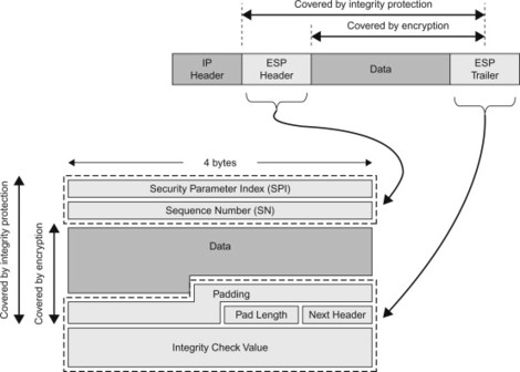
Figure 11.9.2.1 IP packet (data) protected by ESP. (Note that the same packet is shown twice).
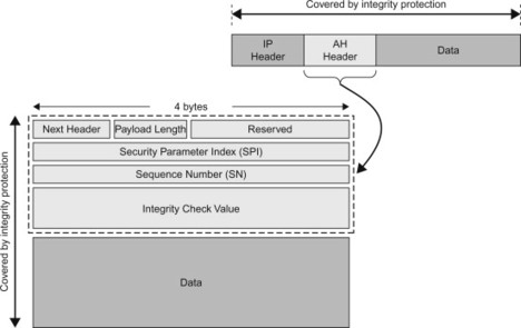
Figure 11.9.2.2 IP packet (data) protected by AH.
The SPI is present in both ESP and AH headers and is a number that, together with the destination IP address and the security protocol type (ESP or AH), allows the receiver to identify the SA to which the incoming packet is bound. The Sequence number contains a counter that increases for each packet sent. It is used to assist in replay protection. The Integrity Check Value (ICV) in the AH header and ESP trailer contains the cryptographically computed integrity check value. The receiver computes the integrity check value for the received packet and compares it with the one received in the ESP or AH packet.
ESP and AH can be used in two modes: transport mode and tunnel mode. In transport mode ESP is used to protect the payload of an IP packet. The Data field as depicted in Figure 11.9.2.1 would then contain, for example, a UDP or TCP header as well as the application data carried by UDP or TCP. See Figure 11.9.2.3 for an illustration of a UDP packet that is protected using ESP in transport mode. In tunnel mode on the other hand, ESP and AH are used to protect a complete IP packet. The Data part of the ESP packet in Figure 11.9.2.1 now corresponds to a complete IP packet, including the IP header. See Figure 11.9.2.4 for an illustration of a UDP packet that is protected using ESP in tunnel mode.
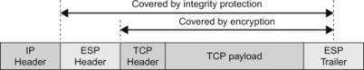
Figure 11.9.2.3 Example of IP packet protected using ESP in transport mode.
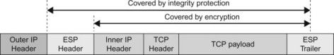
Figure 11.9.2.4 Example of IP packet protected using ESP in tunnel mode.
Transport mode is often used between two endpoints to protect the traffic corresponding to a certain application. Tunnel mode is typically used to protect all IP traffic between security gateways or in VPN connections where a UE connects to a secure network via an un-secure access.
11.9.3 Internet key exchange
In order to communicate using IPSec, the two parties need to establish the required IPSec SAs. This can be done manually by simply configuring both parties with the required parameters. However, in many scenarios a dynamic mechanism for authentication, key generation and IPSec SA generation is needed. This is where the Internet Key Exchange (IKE) comes into the picture. IKE is used for authenticating the two parties and for dynamically negotiating, establishing and maintaining SAs. (One could view IKE as the creator of SAs and IPSec as the user of SAs.) There are in fact two versions of IKE, IKE version 1 (IKEv1) and IKE version 2 (IKEv2).
IKEv1 is based on the Internet Security Association and Key Management Protocol (ISAKMP) framework. ISAKMP, IKEv1 and their use with IPSec are defined in RFC 2407, RFC 2408, [2408] and RFC 2409, [2409]. ISAKMP is a framework for negotiating, establishing and maintaining SAs. It defines the procedures and packet formats for authentication and SA management. ISAKMP is however distinct from the actual key exchange protocols in order to cleanly separate the details of security association management (and key management) from the details of key exchange. ISAKMP typically uses IKEv1 for key exchange, but could be used with other key exchange protocols. IKEv1 has later been replaced by IKEv2 which is an evolution of IKEv1/ISAKMP. IKEv2 is documented in a single document, RFC 4306, [4306], which thus replaces the three RFCs used for documenting IKEv1 and ISAKMP. Improvements have, for example, been made in terms of reduced complexity of the protocol, simplification of the documentation (one RFC instead of three), reduced latency in common scenarios, support for Extensible Authentication Protocol (EAP) and mobility extensions (MOBIKE). Even though IKEv1 is replaced by IKEv2, IKEv1 is still in operational use.
The establishment of an SA using IKEv1 or IKEv2 occurs in two phases. (On this high level, the procedure is similar for IKEv1 and IKEv2). In phase 1 an IKE SA is generated which is used to protect the key exchange traffic. Also mutual authentication of the two parties takes place during phase 1. When IKEv1 is used, authentication can be based on either shared secrets or certificates by using a public key infrastructure (PKI). IKEv2 in addition also supports the use of the EAP and therefore allows a more wide range of credentials to be used, such as SIM cards. See Section 11.10 for more information on EAP. In phase 2, another SA is created which is called the IPSec SA in IKEv1 and child SA in IKEv2. (We will for simplicity use the term IPSec SA for both versions.) This phase is protected by the IKE SA established in phase 1. The IPSec SAs are used for the IPSec protection of the data using ESP or AH. After phase 2 is completed, the two parties can start to exchange traffic using EPS or AH.
EPS makes use of both IKEv1 and IKEv2. The NDS/IP standard allows both IKEv1 and IKEv2 to be used, see Section 7.4. On other interfaces in EPS, it is however primarily IKEv2 that is used. For example, on the SWu interface between UE and ePDG, and on the S2c interface between UE and PDN GW, IKEv2 is used.
11.9.4 IKEv2 mobility and multi-homing
In the IKEv2 protocol, the IKE SAs and IPSec SAs are created between the IP addresses that are used when the IKE SA is established. In the base IKEv2 protocol, it is not possible to change these IP addresses after the IKE SA has been created. There are however scenarios where the IP addresses may change. One example is a multi-homing node with multiple interfaces and IP addresses. The node may want to use a different interface in case the currently used interface suddenly stops working. Another example is a scenario where a mobile UE changes its point-of-attachment to a network and is assigned a different IP address in the new access. In this case the UE would have to negotiate a new IKE SA and IPSec SA which may take a long time and result in service interruption.
In EPS, this may occur if a user is using WLAN to connect to an ePDG. The user traffic between the UE and the ePDG (i.e., on the SWu interface) is protected using ESP in tunnel mode. The IPSec SA for ESP has been set up using IKEv2. (See Section 10.10 for more details). If the user now moves to a different network (e.g., to a different WLAN hotspot) and receives a new IP address from the new network it would not be possible to continue using the old IPSec SA. A new IKEv2 authentication and IPSec SA establishment have to be performed.
The MOBIKE protocol extends IKEv2 with possibilities to dynamically update the IP address of the IKE SAs and IPSec SAs. MOBIKE is defined in RFC 4555, [4555].
MOBIKE is used on the SWu interface to support scenarios where the UE moves between different un-trusted non-3GPP accesses.
11.10 Extensible Authentication Protocol
11.10.1 Overview
The Extensible Authentication Protocol (EAP) is a protocol framework for performing authentication, typically between a UE and a network. It was first introduced for the Point to Point Protocol (PPP) in order to allow additional authentication methods to be used over PPP. Since then it has been introduced also in many other scenarios, for example, as an authentication protocol for IKEv2 as well as for authentication in Wireless LANs using the IEEE 802.11i and 802.1x extensions.
EAP is extensible in a sense that it supports multiple authentication protocols and allows for new authentication protocols to be defined within the EAP framework. EAP is not an authentication method in itself, but rather a common authentication framework that can be used to implement specific authentication methods. These authentication methods are typically referred to as EAP methods.
The base EAP protocol is specified in RFC 3748, [3748]. It describes the EAP packet format as well as basic functions such as the negotiation of the desired authentication mechanism. It also specifies a few simple authentication methods, for example, based on one time passwords as well as a challenge-response authentication similar to CHAP. In addition to the EAP methods defined in RFC 3748, it is possible to define additional EAP methods. Such EAP methods may implement other authentication mechanisms and/or utilize other credentials such as public key certificates or (U)SIM cards. A few of the EAP methods standardized by IETF are briefly described below:
-
EAP-TLS is based on TLS and defines an EAP method for authentication and key derivation based on public key certificates. EAP-TLS is specified in RFC 5216, [5216].
-
EAP-SIM is defined for authentication and key derivation using the GSM SIM card. EAP-SIM also enhances the basic GSM SIM authentication procedure by adding support for mutual authentication. EAP-SIM is specified in RFC 4186, [4186].
-
EAP-AKA is defined for authentication and key derivation using the UMTS SIM card and is based on the UMTS AKA procedure. EAP-AKA is specified in RFC 4187, [4187].
-
EAP-AKA' is a small revision of EAP-AKA that provides for improved key separation between keys generated for different access networks. EAP-AKA' is work in progress in IETF and is defined in RFC 5448, [5448].
In addition to the standardized methods, there are also proprietary EAP methods that have been deployed in corporate WLAN networks.
EPS makes extensive use of EAP-AKA and EAP-AKA' on various interfaces. EAP-AKA is supported for access authentication in un-trusted non-3GPP accesses interworking with the EPC (SWa interface), for tunnel authentication towards the ePDG (SWu and SWm interfaces) as well as for establishing the IPSec SA to be used for DSMIPv6 (S2c and S6b interfaces). EAP-AKA' is supported for access authentication in trusted and un-trusted non-3GPP accesses interworking with the EPC (STa and SWa interfaces). When EAP-based access authentication over STa/SWa is performed it occurs prior to invoking the mobility protocol (PMIPv6, DSMIPv6 or MIPv4). For more details, see the corresponding interface descriptions as well as Chapter 7.
11.10.2 Protocol
The architecture for the EAP protocol distinguishes three different entities:
-
The EAP peer: This is the entity requesting access to the network, typically a UE. For EAP usage in WLAN (802.1x), this entity is also known as the supplicant.
-
The Authenticator: This is the entity performing access control, such as a WLAN access point or an ePDG.
-
The EAP Server: This is the backend authentication server providing authentication service to the authenticator. In EPS, this is the 3GPP AAA Server.
The EAP protocol architecture is illustrated in Figure 11.10.2.1.
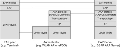
Figure 11.10.2.1 EAP protocol architecture.
EAP is often used for network access control and thus takes place before the UE is allowed access and before the UE is provided with IP connectivity. Between the UE (EAP peer) and the authenticator, EAP messages are typically transported directly over data link layers such as PPP or WLAN (IEEE 802.11), without requiring IP transport. Instead the EAP messages are encapsulated directly in the underlying link layer protocol. There are different specifications for how this transport is provided. For example, RFC 3748, [3748] describes EAP usage for PPP, while IEEE 802.1x describes EAP usage over IEEE 802 links such as WLAN. EAP can also be used for authentication with IKEv2, and in this case is transported over IKEv2 and IP (the IKEv2 and IPSec layers are not illustrated in Figure 11.10.2.1).
Between the authenticator and the EAP server, the EAP messages are typically carried in an AAA protocol such as RADIUS or Diameter.
The EAP communication between the peer and the server is basically transparent to the authenticator. The authenticator therefore need not support the specific EAP method used but needs only to forward the EAP messages between the peer and the server.
An EAP authentication typically begins by negotiating the EAP method to be used. After the EAP method has been chosen by the peers, there is an exchange of EAP messages between the UE and the EAP server where the actual authentication is performed. The amount of round trips needed and the types of EAP messages exchanged depend on the particular EAP method used. When the authentication is complete, the EAP server sends an EAP message to the UE to indicate whether the authentication was successful or not. The authenticator is informed about the outcome of the authentication using the AAA protocol. Based on this information from the EAP server, the authenticator can provide the UE with access to the network, or continue blocking access.
Depending on EAP method, the EAP authentication is also used to derive keying material in the EAP peer and the EAP server. This keying material can be transported from the EAP server to authenticator via the AAA protocol. The keying material can then be used in the UE and in the authenticator for deriving access-specific key needed to protect the access link.
Figure 11.10.2.2 provides an example of an authentication using EAP-AKA. Although not explicitly illustrated in the figure, the EAP messages between the EAP peer and the authenticator are carried over an underlying protocol specific to the type of access. The EAP messages between the authenticator and the EAP server are carried in an AAA protocol such as Diameter. A reader not interested in the particulars of authentication using AKA can disregard the details of the call flow. The interested reader may however want to compare EAP-AKA message exchange in Figure 11.10.2.2 with the EPS-AKA message exchange over E-UTRAN described in, Section 7.3.2. The EPS-AKA over E-UTRAN and the EAP-AKA for accesses supporting EAP are two ways to perform AKA-based authentication.
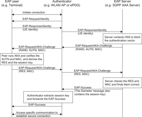
Figure 11.10.2.2 Example message exchange for authentication using EAP-AKA.
11.11 Stream Control Transmission Protocol
11.11.1 Background
The SCTP is a transport protocol, operating at an equivalent level in the stack as UDP (User Datagram Protocol) and TCP. Compared to TCP and UDP, SCTP is richer in functionality and also more tolerant against network failures. Even though both TCP and UDP are used as transport protocols in EPS, we will not describe them in any detail in this book since we assume that most readers have a basic understanding of those protocols. The SCTP on the other hand, also used as transport protocol at several interfaces in EPS, is a less known transport protocol and therefore briefly presented in this section.
SCTP is used on several interfaces in the EPC architecture. In particular the mandated Diameter transport protocol on the S6a/S6d interfaces. SCTP is also used for the transport of S1-AP on the S1-MME interface. More details can be found together with the description of the interfaces in Chapter 10.
Compared to UDP, [768] from 1980 and TCP, [793] from 1981, SCTP is a rather new protocol originally specified in RFC 2960, [2960] from year 2000. The SCTP specification has since then been updated in RFC 4960, [4960] from 2007. The motivation for designing SCTP was to overcome a number of limitations and issues with TCP that are of particular relevance in telecommunication environments. These limitations as well as similarities and differences between UDP/TCP and SCTP are discussed below.
11.11.2 Basic protocol features
SCTP shares many basic features with UDP or TCP. SCTP provides (similar to TCP and in contrast to UDP) a reliable transport ensuring that data reaches the destination without error. Also similar to TCP and in contrast to UDP, SCTP is a connection-oriented protocol meaning that all data between two SCTP endpoints are transferred as part of a session (or association as it is called by SCTP).
The SCTP association must be established between the endpoints before any data transfer can take place. With TCP, the session is set up using a three-way message exchange between the two endpoints. One issue with TCP session setup is that it is vulnerable to so called SYN flooding attacks that may cause the TCP server to overload. SCTP has solved this problem by using a four-way message exchange for the association setup, including the use of a special ‘cookie’ that identifies the association. This makes the SCTP association setup somewhat more complex but brings additional robustness against these types of attacks. An SCTP association as well as the position of SCTP in the protocol stack is illustrated in Figure 11.11.2.1. As is also indicated in the figure, an SCTP association may be utilizing multiple IP addresses at each endpoint (this aspect is further elaborated below).
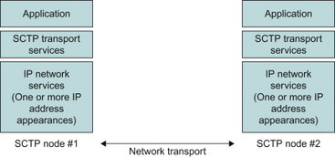
Figure 11.11.2.1 SCTP Association.
Similar to TCP, SCTP is rate adaptive. This means that it will decrease or increase the data transfer rate dynamically, for example, depending on the congestion conditions in the network. The mechanisms for rate adaptation of a SCTP session are designed to behave cooperatively with TCP sessions attempting to use the same bandwidth.
SCTP is, similar to UDP, message-oriented which means that SCTP maintains message boundaries and delivers complete messages (called chunks by SCTP). TCP on the other hand is byte-oriented in the sense that it provides the transport of a byte stream without any notion of separate messages within that byte stream. This is desirable to deliver, for example, a data file or a web page, but may not be optimal to transfer separate messages. If an application sends a message of X bytes and another message of Y bytes over a TCP session, the messages would be received as a single stream of X + Y bytes at the receiving end. Applications using TCP must therefore add their own record marking to separate their messages. Special handling is also needed to ensure that messages are ‘flushed out’ from the send buffer to ensure that a complete message is transferred in a reasonable time. The reason is that TCP normally waits for the send buffer to exceed a certain size before sending any data. This can create considerable delays if the two sides are exchanging short messages and must wait for the response before continuing.
A comparison between SCTP, TCP and UDP is provided in Table 11.11.2.1. More details on the multi-streaming and multi-homing are provided below.
Table 11.11.2.1 Comparison between SCTP, TCP and UDP
| SCTP | TCP | UDP | |
| Connection oriented | Yes | Yes | No |
| Reliable transport | Yes | Yes | No |
| Preserves message boundary | Yes | No | Yes |
| In-order delivery | Yes | Yes | No |
| Un-ordered deliver | Yes | No | Yes |
| Data checksum | Yes (32-bit) | Yes (16-bit) | Yes (16-bit) |
| Flow and congestion control | Yes | Yes | No |
| Multiple streams within a session | Yes | No | No |
| Multi-homing support | Yes | No | No |
| Protection against SYN flooding attacks | Yes | No | N/A |
11.11.3 Multi-streaming
TCP provides both reliable data transfer and strict order-of-transmission delivery of data while UDP does provide neither reliable transport nor strict order-of-transmission delivery. Some applications need reliable transfer but are satisfied with only partial ordering of the data and other applications would want reliable transfer but do not need any sequence maintenance. For example, in telephony signalling it is only necessary to maintain the ordering of messages that affect the same resource (e.g., the same call). Other messages are only loosely correlated and can be delivered without having to maintain a full sequence ordering for the whole session. In these cases, the so called head-of-line blocking caused by TCP may result in unnecessary delay. Head-of-line blocking occurs, for example, when the first message or segment was lost for some reason. In this case the subsequent packets may have been successfully delivered at the destination but the TCP layer on the receiving side will not deliver the packets to the upper layers until the sequence order has been restored.
SCTP solves this by implementing a multi-streaming feature (the name Stream Control Transmission Protocol comes from this feature). This feature allows data to be divided into multiple streams that can be delivered with independent message sequence control. A message loss in one stream will then only impact the stream where the message loss occurred (at least initially) while all other streams could continue to flow. The streams are delivered within the same SCTP association and are thus subject to the same rate and congestion control. The overhead caused by SCTP control signalling is thus reduced.
Multi-streaming is implemented in SCTP by decoupling the reliable transfer of data from the strict-order-of-transmission of the data (Figure 11.11.3.1). This is different from TCP where the two concepts are coupled. In SCTP, two types of sequence numbers are used. The Transport Sequence Number is used to detect packet loss and to control the retransmissions. Within each stream, SCTP then allocates an additional sequence number, the Stream Sequence Numbers. The Stream Sequence Numbers determine the sequence of data delivery within each independent stream and is used by the receiver to deliver the packets in sequence order for each stream.
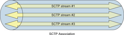
Figure 11.11.3.1 Multi-streaming with SCTP.
SCTP also makes it possible to bypass the sequenced delivery service completely, so that messages are delivered to the user of SCTP in the same order they successfully arrive. This is useful for applications that require reliable transport but do not need in-order delivery, or have their own means to handle sequencing of received packets.
11.11.4 Multi-homing
Another key aspect of SCTP that is an enhancement compared to TCP is the multi-homing features. In telecommunications network it is very important to maintain reliable communications paths to avoid service outage and other problems due to core network transmission problems. Even though the IP routing protocols would be able to find alternative paths in case of a network failure, the time delays until the routing protocol converge and the connectivity is recovered are typically unacceptable in a telecommunications network. Also, if a network node is single homed, that is, has only a single network connection, the failure of that particular connection would make the node unreachable. Redundant network paths and network connections are thus two components in high-available telecommunications systems.
A TCP session involves a single IP address at each endpoint and if one of those IP addresses becomes unreachable, the session fails. It is therefore complicated to use TCP to provide highly-available data transfer capability using multi-homed hosts, that is, where the endpoints are reachable over multiple IP addresses. SCTP on the other hand is designed to handle multi-homed host and each endpoint of an SCTP association can be represented by multiple IP addresses. These IP addresses may also lead to different communication paths between the SCTP endpoints. For example, the IP addresses may belong to different local networks or to different backbone carrier networks.
During the establishment of a SCTP association, the endpoints exchange lists of IP addresses. Each endpoint can be reached on any of the announced IP addresses. One of the IP addresses at each endpoint is established as the primary and the rest become secondary. If the primary should fail for whatever reason, the SCTP packets can be sent to the secondary IP address without the application knowing about it. When the primary IP address becomes available again, the communications can be transferred back. The primary and secondary interfaces are checked and monitored using a heartbeat process that tests the connectivity of the paths (Figure 11.11.4.1).
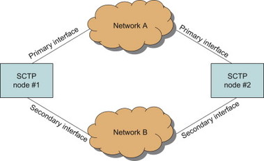
Figure 11.11.4.1 Multi-homing with SCTP.
11.11.5 Packet structure
The SCTP packet is composed of a Common Header and chunks. A chunk contains either user data or control information (Figure 11.11.5.1).
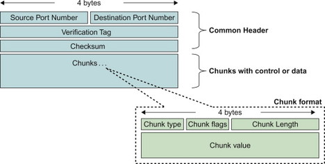
Figure 11.11.5.1 SCTP header and chunk format.
The first 12 bytes make up the Common Header. This header contains the source and destination ports (SCTP uses the same port concept as for UDP and TCP). When an SCTP association is established, each endpoint assigns a Verification Tag. The Verification Tag is then used in the packets to identify the association. The last field of the Common Header is a 32-bit checksum that allows the receiver to detect transmission errors. This checksum is more robust than the 16-bit checksum used in TCP and UDP.
The chunks containing control information or user data follow the Common Header. The chunk type field is used to distinguish between different types of chunks, that is, whether it is a chunk containing user data or control information, and also what type of control information it is. The chunk flags are specific to each chunk type. The chunk value field contains the actual payload of the chunk. RFC 4960, [4960] defines 13 different chunk type values and the detailed format of each chunk type.