
Chapter 6 Session management and mobility
6.1 IP Connectivity and Session Management
LTE and the Enhanced UTRAN introduces significant improvements in the amount of bandwidth provided for wireless transmission using cellular technology, truly paving the way for mobile broadband. In order to provide support for the type of applications and traffic that these access networks would enable, it was necessary to prepare the core network. In conjunction with the evolution of the access networks provided with LTE, the convergence of technologies at the IMS level meant that it was now also possible to provide a common packet core with appropriate policy, security, charging and mobility. This provides end-users with ubiquitous access to network services across different access networks and also provides them with session continuity across the access technologies. This section covers the IP connectivity and the management of the sessions within EPC. A high-level view of the steps involved is shown in Figure 6.1.1.
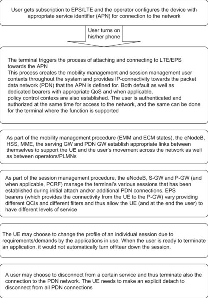
Figure 6.1.1 IP Connectivity flow diagram.
6.1.1 The IP connection
6.1.1.1 General
The most fundamental task of the EPC is to provide IP connectivity to the terminal for both data and voice services. This is maybe an even more significant task than in GSM/WCDMA systems where the circuit-switched domain is also available. With EPS, only the IP-based packet-switched domain is available. Even though there are different possibilities to interwork towards the circuit-switched domain as described in Chapter 5 only the IP-based packet-switched domain is natively supported when using E-UTRAN.
The IP connectivity will have certain properties and characteristics depending on the scenario and the type of services that the user wants to access. First, the IP connectivity will be provided towards a certain IP network. This would in many cases be the Internet but it could also be a specific IP network where the telecom operator provides certain services, for example based on IMS. Then, the IP connectivity would be provided using one or both of the available IP versions, that is IPv4 and/or IPv6. Additionally, the IP connectivity should fulfil certain QoS requirements depending on the service being accessed. For example, the connection may need to provide a certain guaranteed bit rate or allow a prioritized treatment over other connections. The following sections discuss how the above concepts are solved in EPS, both for the 3GPP family of accesses and for other accesses connected to EPC.
6.1.1.2 The PDN connectivity service
As mentioned above, the EPS provides the user with connectivity to an IP network. In EPS, as well as in 2G/3G Packet Core, this IP network is called a ‘Packet Data Network’ (PDN). In EPS, the IP connection to this PDN is called a ‘PDN connection’. Why do we use fancy names such as ‘Packet Data Network’ and ‘PDN connection’? Why not just simply say ‘IP network’ and ‘IP connection’? After all, isn’t this what we actually mean? There are two reasons for this terminology, the first technical and the second historical. First of all, the PDN connection comprises more than just the basic IP access; QoS, charging and mobility aspects are all parts of a PDN connection. Also, when GPRS was originally specified, there was a desire to support different packet data protocol (PDP) types besides IP, such as Point-to-Point Protocol (PPP) (with support for different network-layer protocols) and X.25. Since GPRS could provide access to other PDN types than just IP networks, it made sense at that time to refer to them as PDNs rather than just IP networks. In reality, however, IP-based PDNs became the most commonly used variant in the vast majority of deployments on the market. It has therefore been decided that EPS only supports access to IP-based PDNs using IPv4 and/or IPv6. The name ‘Packet Data Network’, however, remains.
The operator may provide access to different PDNs with different services. One PDN could, for example, be the public Internet. If the user establishes a PDN connection to this ‘Internet PDN’, the user can browse websites on the Internet or access other services available on the Internet. Another PDN could be a specific IP network set up by the telecom operator to provide operator-specific services, for example based on IMS. In summary, if the user establishes a PDN connection to a specific PDN, he or she would only get access to the services provided on that PDN. It is of course possible to provide multiple services in a single PDN. The operator chooses how to configure its networks and services.
A terminal may access a single PDN at a time or it may have multiple PDN connections open simultaneously, for example, to access the Internet and the IMS services simultaneously if those services happen to be deployed on different PDNs. In the latter case, the terminal would have multiple IP addresses, one (or two if both IPv4 and IPv6 are used) for each PDN connection. Each PDN connection represents a unique IP connection, with its own IP address (or pair of IPv4 address and IPv6 prefix) (Figure 6.1.1.2.1).
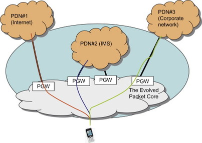
Figure 6.1.1.2.1 UE with multiple simultaneous PDN connections.
One PDN connection is always established when the terminal attaches to the EPS (refer to Chapter 12 for a high-level description of the attach procedure for the different accesses). During the attach procedure, the terminal may provide information about the PDN that the user wants to access. The information is carried in a parameter called ‘Access Point Name’ (APN). The APN is a character string that contains a reference to the PDN where the desired services are available. The network uses the APN when selecting the PDN for which to set up the PDN connection; the operator defines what APNs (and corresponding PDNs) are available to a user as part of their subscription. In case the terminal does not provide any APN during the attach procedure, the network will use a default APN defined as part of the user’s subscription profile in the HSS in order to establish the PDN connection. It can be noted that the APN is used to select not only PDN but also the PDN GW providing access to that PDN. These selection functions are described in more detail in Chapter 9.
Additional PDN connections may be established when the terminal is attached to EPS. In this case the terminal sends a request to the network to open a new PDN connection. The request must always contain an APN to inform the network about what PDN that the user wants to access.
The terminal may at any time close a PDN connection.
6.1.1.3 Relation between EPC, application and transport layers
The PDN connection provides the user with an IP connection to a PDN. When a PDN connection is established, context data representing the connection is created in the UE, the PDN GW and, depending on access technology used, also in other core networks nodes in between, for example the MME and Serving GW for E-UTRAN access. The EPS is concerned with this ‘PDN connection layer’ and the associated functions such as IP address management, QoS, mobility, charging, security, policy control, etc.
The PDN connection is a logical connection between a specific IPv4 address and/or IPv6 prefix allocated to a UE and a particular PDN. The user data belonging to the PDN connection is transported between the terminal and the base station over the underlying radio connection. The user data is also carried by an underlying transport network between the network entities in the EPC. At the same time, the application (or service) that the user may be running is transported on top of the PDN connection. Here, and in the following few sections, we use the term ‘application’ in a generic manner, including protocol layers on top of IP.
The transport network in the EPC provides an IP transport that can be deployed using different technologies such as MPLS, Ethernet, wireless point-to-point links, etc. Over the radio interface, the PDN connection is transported on top of a radio connection between the UE and the base station. Figure 6.1.1.3.1 provides an illustration of the relation between application layer, PDN connection ‘layer’ and transport layer. The IP transport layer entities in the backbone network, such as IP routers and layer 2 switches, are not aware of the PDN connections as such. In fact, these entities are typically not aware of per-user aspects at all. Instead they operate on traffic aggregates and if any traffic differentiation is needed, it is typically based on Differentiated Services (DiffServ) and techniques operating on traffic aggregates.
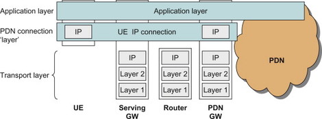
Figure 6.1.1.3.1 Schematic view of application, PDN connection and transport layers for 3GPP family of accesses.
Figure 6.1.1.3.1 provides a schematic illustration of the application layer, PDN connection ‘layer’ and transport layer for EPS when the UE is connected over a GERAN, UTRAN or E-UTRAN access. It can be noted that the user IP connection (the PDN connection) is separate from the IP connection between the EPC nodes (the transport layer). This is a common feature in mobile networks where the user plane is tunnelled over a transport network in order to provide per-user security, mobility, charging, QoS, etc. This distinction between PDN connection and transport layer is also important when we come into aspects related to IP address allocation, QoS, etc., below.
Figure 6.1.1.3.1 also illustrates the different layers in the case where the UE is connected to EPC over other accesses. In general, an IP-based transport layer below the PDN connection layer is present for all cases. It should, however, be noted that the details regarding the protocol layers below the PDN connection layer depends on what mobility protocol is used and what other protocols are used when accessing over a non-3GPP access.
6.1.1.4 IP addresses
A key task of the EPS is to provide IP connectivity between a UE and a PDN. The IP address allocated to the UE comes from the PDN where the UE is accessing. It should be noted that this IP address, and the IP address domain of the PDN, is different from the IP network (or backbone) that provides the IP transport between nodes within the EPC. The backbone providing the IP transport in the EPC can be a purely private IP network used solely for the transport of PDN connections and other IP-based signalling in the EPC, either for a single operator in non-roaming cases or between operators in roaming scenarios. The PDN is, however, an IP network where a user gets access and is provided services, for example the Internet. This section is only concerned with the IP addresses allocated to the UE.
Each PDN may provide services using IPv4 and/or IPv6. A PDN connection must thus provide connectivity using the appropriate IP version. Currently, the majority of the IP networks where end-users get access, for example using GPRS or fixed broadband accesses, is based on IPv4. That is, the user will be assigned an IPv4 address and access IPv4-based services. Also, most services available on the Internet are IPv4 based. It is likely, however, that IPv6 deployments will become more common in the EPS/E-UTRAN time frame and it is thus important that EPS provides efficient support for both IPv4 and IPv6, for example, to allow easy migration and co-existence.
Usage of IPv6 instead of IPv4 is primarily motivated by the vast number of IPv6 addresses available for allocation to devices and terminals. Some operators are already experiencing or will soon experience shortages of IPv4 addresses to varying degrees. The allocation of IPv4 addresses across the world and between organizations differs greatly. IPv6 does not have this problem since the addresses are 128 bits long, in theory providing 2128 addresses. In comparison to the 32 bits used for IPv4, IPv6 therefore provides significantly more addresses.
However, since the IP infrastructure and applications on both private networks and the Internet are still mostly based on IPv4, the introduction of IPv6 is a great challenge in terms of migration and smooth introduction. This is because IPv4 and IPv6 are not interoperable protocols; IPv6 implements a new packet header format, designed to reduce the amount of processing an IP header requires. Thanks to this fundamental difference in headers, workarounds are needed to get them functioning on the same network. Multiple mechanisms exist allowing, for example, devices using IPv6 to communicate with applications based on IPv4 (as they are on the Internet) as well as transporting IPv6 packets over IPv4 infrastructure. These solutions all have their pros and cons but details about these are beyond the scope of this book. Interested readers are referred to the many excellent books on IPv6 available; some examples are, [Li, 2006] and, [Blanchet, 2006] but many others exist.
In the 2G/3G core network, each PDN connection (i.e. PDP context) supports one IP address only. In order for a terminal to request both an IPv4 and an IPv6 address/prefix, it has to activate two PDN connections (two ‘primary’ PDP contexts), one for each IP version. With EPS, this has changed. A terminal activating a PDN connection in EPS may request an IPv4 address, an IPv6 prefix or both for that PDN connection. That is, EPS supports three types of PDN connections; IPv4 only, IPv6 only, as well as dual stack IPv4/IPv6. It can be noted that in 3GPP Rel-9, support for dual stack PDP context is also introduced in the 2G/3G GPRS core network.
EPS supports different ways to allocate an IP address. The IP address may be assigned using different protocols depending on what access is used. The detailed procedure for allocating an IP address also depends on deployment aspects as well on the IP version (v4 or v6). This is explained in more detail in the following sections.
IP address allocation in 3GPP accesses
The method to allocate IPv4 addresses and IPv6 prefixes are different. Below we will describe how IPv4 addresses and IPv6 prefixes are allocated in EPS. There are two main options for allocating in IPv4 address to the UE in 3GPP access:
-
One alternative is to assign the IPv4 address to the UE during the attach procedure (E-UTRAN) or PDP context activation procedure (GERAN/UTRAN). In this case the IPv4 address is sent to the UE as part of the attach accept message (E-UTRAN) or Activate PDP Context Accept message (GERAN/UTRAN). This is a 3GPP-specific method of assigning an IP address and this is the way it works in most 2G/3G networks. The terminal will also receive other parameters needed for the IP stack to function correctly (e.g. DNS address) during the attach (E-UTRAN) or during PDP context activation (GERAN/UTRAN). These parameters are transferred in the so-called Protocol Configurations Options (PCO) field.
-
The other alternative is to use DHCPv4 (often referred to as just DHCP). In this case the UE does not receive an IPv4 address during attach or PDP context activation. Instead the UE uses DHCPv4 to request an IP address after attach (E-UTRAN) and PDP context activation (for GERAN/UTRAN) is completed. This method to allocate IP addresses is similar to how it works, for example, in Ethernet and WLAN networks where terminals use DHCP after the basic layer 2 connectivity has been set up. When DHCP is used, the additional parameters (e.g. DNS address) are also sent to the UE as part of the DHCP procedure.
Whether alternative 1 or 2 is used in a network depends on what is requested by the UE as well as what is supported and allowed by the network. It should be noted that both these alternatives are supported already in 2G/3G core network standards even though alternative 1 is used in the vast majority of existing 2G/3G networks. One difference is, however, that in 2G/3G core networks, the selected IPv4 allocation method (alt 1 or 2) is configured per APN. This means that only one method is supported for each APN. In EPS, however, this has been made more flexible to allow both methods to co-exist for the same APN. It is still possible to deploy an EPS network so that only one method per APN is used, if desired.
We now proceed to the IP address allocation procedure for IPv6. The only method currently supported in EPS is stateless IPv6 address auto configuration. For more details on basic IPv6 features, please refer to, [Hagen, 2006]. When IPv6 is used, a /64 IPv6 prefix is allocated for each PDN connection and UE. The UE can utilize the full prefix and can construct the IPv6 address by adding an Interface Identifier to the IPv6 prefix. Since the full /64 prefix is allocated to the UE and the prefix is not shared with any other node, the UE does not need to perform Duplicate Address Detection (DAD) to verify that no one else is using the same IPv6 address.
With stateless IPv6 address auto configuration, attach and (for GERAN/UTRAN) PDP context activation are completed first. The GW then sends an IPv6 Router Advertisement (RA) to the UE after attach and PDP context activation are completed. The RA contains the IPv6 prefix that is allocated to this PDN connection. The RA is sent over the already established PDN connection and is therefore sent only to a specific terminal. This is different compared to some non-3GPP access networks where many terminals share the same layer 2 link (e.g. Ethernet). In these networks the RA is sent as a broadcast to all connected terminals. After completing the IPv6 stateless address auto configuration, the terminal can use stateless DHCPv6 to request other necessary parameters, for example, DNS address. The option to allocate IPv6 prefix(es) using stateful DHCPv6 is currently not supported by EPS.
IP address allocation in other accesses
The way by which IPv4 addresses and/or IPv6 prefixes are assigned in other accesses differs depending on what access is used and what mobility protocol (PMIPv6, MIPv4 or DSMIPv6) is used.
When the terminal attaches from a trusted non-3GPP access and PMIPv6 is used on the S2a interface, the address allocation is quite similar to how it works in 3GPP accesses. An access may, for example, have access specific means to deliver IPv4 address to the UE, or DHCPv4 may be used. For IPv6, stateless IPv6 address auto configuration is typically supported. The IP layers are illustrated in Figure 6.1.1.4.1.
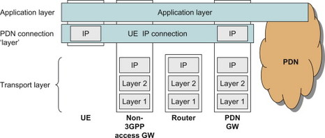
Figure 6.1.1.4.1 Schematic view of application, PDN connection and transport layers for trusted non-3GPP accesses when PMIP is used on S2a.
When the terminal attaches in an untrusted access and PMIPv6 is used on S2b interface, the terminal receives the IP address from the PDN during the IKEv2-based authentication with the ePDG. It can be noted that before IKEv2 is performed and the IPSec tunnel is setup, an additional IP address is involved. The reason is that the terminal needs local IP connectivity from the untrusted non-3GPP access in order to communicate with the ePDG. This local IP address does, however, not come from a PDN but is only used to setup the IPSec tunnel. This is illustrated in Figure 6.1.1.4.2. For more details, see [Ch 12.1].
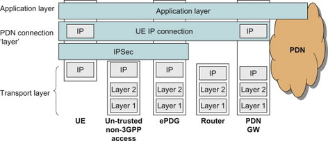
Figure 6.1.1.4.2 Schematic view of application, PDN connection and transport layers for un-trusted non-3GPP accesses when PMIP is used on S2b.
From an IP address allocation point of view, the situation is rather similar when DSMIPv6 is used. The terminal receives its IP address (also referred to as Home Address in Mobile IP terminology) during the DSMIPv6 bootstrapping with the PDN GW. However, the terminal first needs to acquire a local IP address to be used as Care-of Address. Therefore the UE has two IP addresses, one for the local connection (Care-of Address) and one for the PDN connection (Home Address). This is illustrated in Figure 6.1.1.4.3.
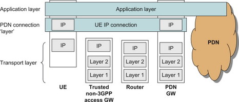
Figure 6.1.1.4.3 Schematic view of application, PDN connection and transport layers for trusted non-3GPP accesses when DSMIPv6 (S2c) is used.
The most involved case, which is not shown in the figure, is when DSMIPv6 is used over untrusted non-3GPP accesses. In this case the terminal uses three IP addresses, a local IP address to establish the IPSec tunnel towards an ePDG, the IP address received from ePDG which is used as a Care-of Address and then finally the IP address for the PDN connection received during DSMIPv6 bootstrapping with the PDN GW.
For more details on DSMIPv6, see [ Chapter 11.3] and [ Chapter 12.1].
6.2 Session Management, Bearers and QoS Aspects
6.2.1 General
Providing PDN connectivity is not just about getting an IP address; it is also about transporting the IP packets between the UE and the PDN in such a way that the user is provided a good experience of the service being accessed. Depending on whether the service is a voice call using Voice over IP, a video streaming service, a file download, a chat application, etc., the QoS requirements for the IP packet transport are different. The services have different requirements on the bit rates, delay, jitter, etc. Furthermore, since radio and transport network resources are limited and many users may share the same available bandwidth, efficient mechanisms must be available to partition the available (radio) resources between the applications and the users. The EPS needs to ensure that all these different service requirements are supported and that the different services receive the appropriate QoS treatment in order to enable a positive user experience.
This section describes the basic functions in EPS to manage the user plane path between the UE and the PDN GW. One key task of the session management features is to provide a transmission path of a well-defined QoS. The basic principles around session management are covered in this chapter, but the more detailed QoS aspects can be found in the subsequent chapters on QoS.
In the subsections below we introduce the ‘EPS bearer’ which is a central concept in E-UTRAN and EPS both for providing the IP connection as such and for enabling QoS. We also look at several aspects related to how GERAN and UTRAN accesses are connected to EPS, however, without going into the same level of detail regarding session management for GERAN/UTRAN. Finally we look at similar aspects for other accesses connected to EPS.
6.2.2 The EPS bearer for E-UTRAN access
For E-UTRAN access in EPS, one basic tool to handle QoS is the ‘EPS bearer’. In fact, the PDN connectivity service described above is always provided by one or more EPS bearers (also denoted just ‘bearer’ for simplicity). The EPS bearer provides a logical transport channel between the UE and the PDN for transporting IP traffic. Each EPS bearer is associated with a set of QoS parameters that describe the properties of the transport channel, for example bit rates, delay and bit error rate, scheduling policy in the radio base station, etc. All conformant traffic sent over the same EPS bearer will receive the same QoS treatment. In order to provide different QoS treatment to two IP packet flows, they need to be sent over different EPS bearers. All EPS bearers belonging to one PDN connection share the same UE IP address. The QoS aspects and its relation to the EPS bearers will be discussed in more detail in, Section 8.1.
6.2.2.1 Default and dedicated bearers
A PDN connection has at least one EPS bearer but it may also have multiple EPS bearers in order to provide QoS differentiation to the transported IP traffic. The first EPS bearer that is activated when a PDN connection is established is called the ‘default bearer’. This bearer remains established during the lifetime of the PDN connection. Even though it is possible to have an enhanced QoS for this bearer, in most cases the default bearer will be associated with a default type of QoS and will be used for IP traffic that does not require any specific QoS treatment. Additional EPS bearers that may be activated for a PDN connection are called ‘dedicated bearers’. This type of bearer may be activated on demand; for example, in case an application is started that requires a specific guaranteed bit rate or a prioritized scheduling. Since dedicated bearers are only set up when they are needed, they may also be deactivated when the need for them no longer exist, for example, in case the application that needs the specific QoS treatment is no longer running.
6.2.2.2 User plane aspects
The UE and the PDN GW (for GTP-based S5/S8) or Serving GW (for PMIP-based S5/S8) use packet filters to map IP traffic onto the different bearers. Each EPS bearer is associated with a so-called Traffic Flow Template (TFT) that includes the packet filters for the bearer. These TFTs may contain packet filters for uplink traffic (UL TFT) and/or downlink traffic (DL TFT). The TFTs are typically created when a new EPS bearer is established, and they are then modified during the lifetime of the EPS bearer. For example, when a user starts a new service, the filters corresponding to that service can be added to the TFT of the EPS bearer that will carry the user plane for the service session. The filter content may come either from the UE or from the PCRF (see Section 8.2 on PCC for more details).
The TFTs contain packet filter information that allows the UE and PGW to identify the packets belonging to a certain IP packet flow aggregate. This packet filter information is typically a 5-tuple defining the source and destination IP addresses, source and destination port as well as protocol identifier (e.g. UDP or TCP). It is also possible to define other types of packet filters based on other parameters related to an IP flow. The filter information may contain the following attributes:
-
Remote IP Address and Subnet Mask
-
Protocol Number (IPv4)/Next Header (IPv6)
-
Local Port Range
-
Remote Port Range
-
IPSec Security Parameter Index (SPI)
-
Type of Service (TOS) (IPv4)/Traffic class (IPv6)
-
Flow Label (IPv6).
The word ‘remote’ refers to the entity on the external PDN with which the UE is communicating while ‘local’ refers to the UE itself. The UE IP address is not contained in the TFT since it is understood that the UE is only assigned a single IP address, or possibly a single IP address of each IP version, per PDN connection.
Some of the above-listed attributes may co-exist in a packet filter while others mutually exclude each other. Table 6.2.2.2.1 lists the different packet filter attributes and possible combinations. Each packet filter in a TFT is associated with a precedence value that determines in which order the filters shall be tested for a match.
Table 6.2.2.2.1 Valid packet filter attribute combinations.
| Valid combination types | |||
| Packet filter attribute | I | II | III |
| Remote address and subnet mask | X | X | X |
| Protocol number (IPv4)/next header (IPv6) | X | X | |
| Local port range | X | ||
| Remote port range | X | ||
| IPSec SPI | X | ||
| TOS (IPv4)/traffic class (IPv6) and mask | X | X | X |
| Flow label (IPv6) | X | ||
An example for how a TFT is used could be that the UE starts an application that connects to a media server in the PDN. For this service session, a new EPS bearer may be set up with the appropriate QoS parameters and bit rates. At the same time, packet filters are installed in the UE and the PDN GW that directs all traffic for the corresponding media onto that newly established EPS bearer. The Policy and Charging Control (PCC) system may be used at service establishment to ensure that the right QoS and TFT is provided.
When an EPS bearer is established, a bearer context is created in all EPS nodes that need to handle the user plane and identify each bearer. For E-UTRAN and a GTP-based S5/S8 interface between Serving GW and PDN GW, the UE, eNodeB,MME, Serving GW and PDN GW will all have bearer context. The exact details of the bearer context will differ somewhat between the nodes since the same bearer parameters are not relevant in all nodes. Furthermore, as will be seen further below, when PMIP-based S5/S8 is used, the PDN GW will not be aware of the EPS bearers.
Between the core network nodes in EPC, the user plane traffic belonging to a bearer is transported using an encapsulation header (tunnel header) that identifies the bearer. The encapsulation protocol is GTP-U. When E-UTRAN is used, GTP-U is used on S1-U and can also be used on S5/S8. The other alternative, to use PMIP on S5/S8 is described further below. The GTP-U header contains a field that allows the receiving node to identify the bearer the packet belongs to Figure 6.2.2.2.1 illustrates two EPS bearers in a GTP-based system. A user plane packet encapsulated using GTP-U is illustrated in Figure 6.2.2.2.2. For more information on GTP, see Section 11.2.
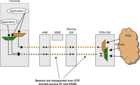
Figure 6.2.2.2.1 EPS bearer for GTP-based system.
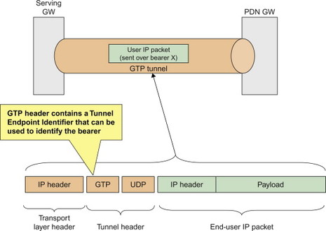
Figure 6.2.2.2.2 EPS bearer transport for GTP-based system.
6.2.2.3 PDN connections, EPS bearers, TFTs and packet filters – bringing it all together
In this chapter we have so far described several different concepts used in EPS and E-UTRAN to provide IP connectivity to a PDN and provide an appropriate packet transport; PDN connections, EPS bearers, TFTs and packet filters. Before going into more details on bearer procedures in EPS, it may be useful to see how they all relate to each other. Figure 6.2.2.3.1 provides an illustration of how the UE, PDN connection, EPS bearer, TFT and packet filters within the TFT relate to each other.
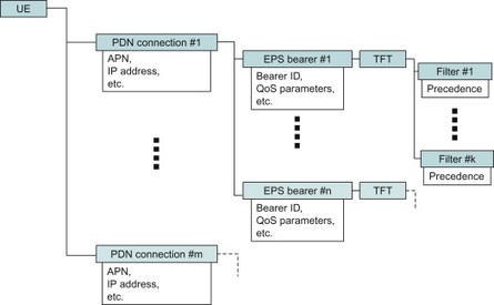
Figure 6.2.2.3.1 Schematic relation between UE, PDN connection, EPS bearer, TFT and packet filters.
6.2.2.4 Control plane aspects
There are several procedures available in EPS to control the bearers. These procedures are used to activate, modify and deactivate bearers as well as to assign QoS parameters; packet filters, etc., to the bearer. Note, however, that if the default bearer is deactivated the whole PDN connection will be closed. EPS has adopted a network-centric QoS control paradigm, meaning that it is basically only the PDN GW that can activate, modify and deactivate an EPS bearer and decide which packet flows are transported over which bearer. It may be noted that this network-centric approach is different from pre-EPS GPRS. In GPRS it was originally only the UE that would take the initiative to establish a new bearer (or PDP context as the bearers are called in GPRS) and decide on what packet flows to transport over that PDP context. In 3GPP Rel-7, the NW-initiated bearer procedures were introduced by specifying a new procedure with the long name ‘network-requested secondary PDP context activation procedure’. In this procedure it is the GGSN that takes the initiative to create a ‘dedicated bearer’, known as secondary PDP context in 2G/3G packet core, as well as to assign packet filters. The move towards a network-centric approach has been taken one step further with EPS, since it is now only the PDN GW that can activate a new bearer and decide which packet flows are transported over which bearer. For more information on the network-centric QoS control paradigm, see Section 8.1.
It should be noted that when an EPS bearer is established or modified, the state in the radio access may also be modified to provide an appropriate radio layer transport for each active EPS bearer. More information about this can be found in, [Dahlman, 2008] and, Section 8.1.
6.2.2.5 Bearers in PMIP- and GTP-based deployments
In the illustration for bearers in GTP-based systems above, the EPS bearers extend between the UE and the PDN GW. This is how it works when GTP is used between Serving GW and PDN GW. As explained in Chapter 3 it is also possible to deploy EPS with PMIP between Serving GW and PDN GW. While GTP is designed to support all functionality required to handle the bearer signalling as well as the user plane transport, PMIP was designed by IETF to only handle functions for mobility and forwarding of the user plane. PMIP thus had no built-in features to bearers or QoS-related signalling. During 2007 there were long discussions in 3GPP whether PMIP should be extended to support bearer-related signalling as well as to allow user plane marking to identify the EPS bearers, similar to GTP. It was eventually decided, however, that the PMIP-based reference points would not be aware of the EPS bearers. This means that it is not possible for the bearers to extend all the way between UE and PDN GW. Instead the bearers are only defined between UE and Serving GW when PMIP-based S5/S8 is used. Consequently, it is not sufficient to have the packet filters only in UE and PDN GW. Without bearer markings between S-GW and PDN GW, also the Serving GW would need to know the packet filters in order to map the downlink traffic onto the appropriate bearer towards the UE. This is illustrated in Figure 6.2.2.5.1.
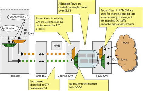
Figure 6.2.2.5.1 EPS bearer when PMIP-based S5/S8 is used.
The observant reader has noticed from Figure 6.2.2.5.1 that the PDN GW still uses the packet filters, just as with the GTP-based S5/S8. Why is this so? Isn’t it enough that Serving GW has the packet filters in this case? It is true that the PDN GW does not need the packet filters to do the bearer mapping of downlink traffic, since this is instead done by the Serving GW when PMIP-based S5/S8 is used. The PDN GW, however, still performs important functionality such as bit rate enforcement and charging for the different IP flows. This is not directly related to the EPS bearers but it is the reason why PDN GW has packet filter knowledge also for PMIP-based S5/S8. These functions of the PDN GW, common to both PMIP-based S5/S8 and GTP-based S5/S8, are further described in, Section 8.2 on PCC.
6.2.3 Session management for EPS and GERAN/UTRAN accesses
The 2G/3G Core Network uses the concept of PDP contexts to provide PDN connectivity and QoS management in the core network. The PDP context is defined between the UE and the GGSN and defines all the information used for a certain connection, including PDP address, QoS class, etc. The PDP context corresponds to EPS bearers for E-UTRAN.
The PDP context concept is partially maintained also when 2G/3G accesses are connected to EPC. In principle it would have been possible to replace the PDP context procedures for 2G/3G with the EPS bearer procedures but it was considered preferable to maintain the PDP context procedures, at least between UE and the SGSN. Within the EPC, however, the EPS bearer procedures are used also when the UE is in 2G/3G access. The SGSN provides the mapping between PDP context and EPS bearer procedures, and maintains a one-to-one mapping between PDP contexts and EPS bearers. There are several reasons why this architecture is preferable:
-
By using PDP context procedures between UE and SGSN, the UE can use similar ways to connect when the 2G/3G access connects to EPC as when it connects to the GPRS architecture.
-
By using the EPS bearer in the EPC also for 2G/3G access, it is easier for the PDN GW to handle mobility between E-UTRAN and 2G/3G. Since there is a one-to-one mapping between PDP context and EPS bearer, the handover between 2G/3G access and E-UTRAN access is simplified.
The interfaces where PDP context procedures are used and where EPS bearer procedures are used respectively are illustrated in Figure 6.2.3.1.
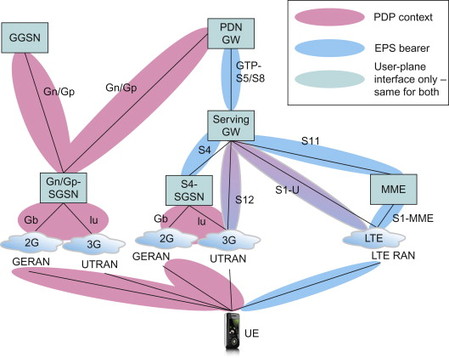
Figure 6.2.3.1 Usage of PDP context procedures and EPS bearer procedures for EPS as well as for EPS interworking with Gn/Gp-based SGSNs.
An SGSN using S4 maps the UE-initiated PDP context procedures (activation/modification/deactivation) over GERAN/UTRAN into corresponding EPS bearer procedures towards the Serving GW. One aspect that complicates this mapping is the fact that PDP contexts are controlled by the UE while EPS bearers are controlled by the NW. One consequence is that the PDN GW needs to be aware that the UE is using 2G/3G and adjust its behaviour appropriately. For example,in case the UE is using GERAN/UTRAN and has requested activation of a secondary PDP context, the PDN GW must activate a new EPS bearer corresponding to the PDP context. This is not the case if the UE is using E-UTRAN. In this case the UE cannot directly request activation of an EPS bearer, the UE can only make a request for certain resources and the PDN GW can decide whether or not to activate a new EPS bearer or modify an existing EPS bearer.
The SGSN also needs to map parameters provided from the UE (e.g. QoS parameters defined according to pre-rel-8 GPRS) into corresponding EPS parameters towards the Serving GW. See Section 8.1 for further details on QoS.
Another aspect that is worth mentioning in this context is that a Gn/Gp-SGSN may select either a PDN GW (supporting Gn/Gp) or a GGSN. See Chapter 9 for more details on the selection functions.
6.2.4 Session management for other accesses
In the previous subsections we have described session management for the 3GPP family of accesses and the use of bearers (i.e. EPS bearers and PDP contexts) to handle the user plane path between the UE and the network. It was found that the bearer is the basic enabler for traffic separation, that is, providing differential treatment for traffic with differing QoS requirements. The bearer procedures are specific to the 3GPP family of accesses but other accesses may have similar features and procedures to manage the user plane path and to provide traffic separation between different types of traffic. The details of the QoS mechanisms and the terminology used may differ between the different access technologies, but the key function to provide differentiated treatment for traffic with differing QoS requirements is common to all accesses that are able to provide QoS support. There are also accesses that basically only support best effort delivery of packets, without any differentiated treatment. Most vanilla IEEE 802.11b WLAN networks fall into that category.
We will not describe the access specific QoS ‘bearer’ capabilities and procedures that may be supported by the different accesses outside the 3GPP family of accesses. We will, however, look at how QoS is managed using the PCC architecture when these accesses interwork with EPS as described in, Section 8.2.
6.3 Mobility Principles
6.3.1 General
In the early days of GSM, the system supported a single radio access technology (GSM) and there was no mobility to/from other technologies. Since then 3GPP has developed WCDMA and LTE. 3GPP2 has developed CDMA (1xRTT and HRPD) and in addition other foras have developed a multitude of access technologies, such as WLAN or WiMAX, and fixed access, such as xDSL, Passive optical Networks (PON) or Cable. With such a range of access technologies available to the users to pick from and also for operators to select as their preferred system of choice, mobility has become quite complex. There is definitely a need and desire to find a ‘common’ set of tools allowing the end-user’s devices to converge towards supporting a core set of mobility mechanisms.
With EPS, 3GPP aimed to provide not only a common core network for all access technologies but also mobility between heterogeneous access technologies. EPS is the first complete realization of multi-access convergence; a packet core network that supports full mobility management, access network discovery and selection for any type of access network.
In this section we will give an overview of the mobility functionality in EPS, starting from the mobility functionality for LTE, WCDMA and GSM, then adding on HRPD, WLAN and other radio technologies.
Mobility is the core feature of mobile systems, and many of the major system design decisions for EPC are derived directly from the necessity of ensuring mobility. The functionality of mobility management is required to ensure the following:
-
That the network can ‘reach’ the user, for example, in order to notify the terminal about incoming calls
-
That a user can initiate communication towards other users or services such as Internet access, and
-
That ongoing sessions can be maintained as the user moves.
Associated functionality also ensures the authenticity and validity of the user’s access to the system. It authenticates and authorizes the subscription and prepares the network and the user’s device (i.e. the UE) with subscription information and security credentials.
6.3.2 Mobility within 3GPP family of accesses
6.3.2.1 Cellular idle-mode mobility management
Idle-mode mobility management in cellular systems like LTE, GSM/WCDMA and CDMA is built on similar concepts. To be able to reach the UE, the network tracks the UE, or rather the UE updates the network about its location, on a regular basis. The radio networks are built by cells that range in size from tens and hundreds of metres to tens of kilometres. It would not be practical and would cause a lot of signalling to keep track of a UE in idle mode every time it moves in between different cells. It is also not practical to search for the UE in the whole network for every terminating event (e.g. an incoming call). Hence the cells are grouped together into ‘registration areas’ (Figure 6.3.2.1).
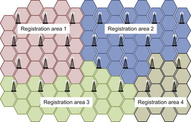
Figure 6.3.2.1 Registration areas.
The base stations broadcast registration area information and the UE compares the broadcasted registration area information with the information it has previously stored. If the registration area information does not match the information stored in the UE, it starts an update procedure towards the network to inform that it is now in a different registration area.
For example, when a UE that was previously in registration area 1 moves into a cell in registration area 2, it will notice that the broadcast information includes a different registration area identity. This difference in the stored and broadcasted information triggers the UE to perform a Registration update procedure towards the NW. In the Registration update procedure, the UE informs the network about the new registration area it has entered. Once the network has accepted the registration update, the UE will store the new registration area.
In EPS the registration areas are called Tracking Areas (TA). In order to distribute the registration update signalling the concept of tracking area lists was introduced in EPS. The concept allows a UE to belong to a list of different TAs. Different UEs can be allocated to different lists of tracking areas. As long as the UE moves within its list of allocated TA list, it does not have to perform tracking area update. By allocating different lists of tracking areas to different UEs, the operator can give UE’s different registration area borders and by that reduce peaks in registration update signalling, for example, when a train passes a TA border.
In addition to the registration updates performed when passing a border to a TA where the UE is not registered, there is also a concept of periodic updates. Periodic updates are used to ensure that the NW does not continue to page for UEs that are out of coverage or have been turned off.
The size of the tracking areas/tracking area lists is a compromise between registration update load and the paging load in the system. The smaller the areas you have, the fewer the cells you need to page the UEs in. On the other hand you will have frequent TA updates. The larger the area you have, the higher the paging load in the cells, but less tracking area updates signalling. In LTE, the concept of tracking area lists can also be used to reduce the frequency of tracking area updates. If you, for example, can predict the movement of UEs, the lists can be adapted for an individual UE to ensure that they pass fewer borders and UEs that receive lots of paging messages can be allocated smaller TA lists, while UEs that are paged infrequently can be paged less frequently.
In GSM/WCDMA there are two registration area concepts: one for PS domain (routing areas) and the other for CS domain (location areas). GSM and WCDMA cells may be included in the same Routing and Location Areas, allowing the UE to move between technologies without performing Routing Area Updates (RAU). The Routing Areas are a subset of the Location Areas and can only contain cells from the same LA. There is no support for lists of routing or location areas in GSM/WCDMA and hence all UEs share the same RA/LA borders. There is, however, another optimization that has been introduced in GSM/WCDMA, since the RA is a subset of the LA; the UE can perform combined RAU/LAU where the UE is tracked on an RA basis. Since the RA is a subset of the LA, the network also knows in which LA the UE is. The UE can hence perform the combined updates when crossing the RA borders and no extra LAU procedures are needed. This optimization does, however, require support in both the UE and the NW. The combined update procedure is gaining momentum in GSM deployments while so far it has not been deployed much in WCDMA networks.
| Generic concept | EPS | GSM/WCDMA GPRS | GSMWCDMA CS |
| Registration area | List of tracking areas (TA list) | Routing Area (RA) | Location Area (LA) |
| Registration area update procedure | TA Update procedure | RA Update procedure | LA Update procedure |
Summary of Idle mobility procedure in EPS:
-
A TA consists of a set of cells
-
The registration area in EPS is a list of one or more TAs
-
The UE performs TA Update when moving outside its TA list
-
The UE also performs TA Update when the periodic TA Update timer expires. An outline of the Tracking Area Update procedure is shown in Figure 6.3.2.2 and it contains the following steps:
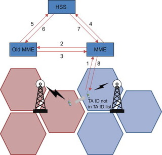
Figure 6.3.2.2 TAU procedure.
-
When the UE reselects a new cell and realizes that the broadcasted TA ID is not in their list of TAs, the UE initiates a TAU procedure to the network. The first action is to send a TA update message to the MME.
-
Upon reception of the TA message from the UE, the MME check if a context for that particular UE is available, if not it checks the UE’s temporary identity to determine which node that keeps the UE context. Once this is determined the MME asks the old MME for the UE context.
-
The old MME transfers the UE context to the new MME.
-
Once the MME has received the old context, it informs the HSS that the UE context is now moved to a new MME.
-
The HSS cancels the UE context in the old MME.
-
The HSS acknowledge the new MME and inserts new subscriber data in the MME.
-
The MME informs the UE that the TAU was successful and as the MME was changed it supplies a new GUTI (where the MME code points back to the new MME).
6.3.2.2 Paging
Paging is used to search for idle UEs and establish a signalling connection. Paging is, for example, triggered by downlink packets arriving to the Serving GW. When the Serving GW receives a downlink packet destined for an Idle UE, it does not have an eNodeB address to which it can send the packet. The Serving GW instead informs the MME that a downlink packet has arrived. The MME knows in which TA the UE is roaming and it sends a paging request to all eNodeBs within the TA lists. Upon reception of the paging message, the UE responds to the MME and the bearers are activated so that the downlink packet may be forwarded to the UE.
6.3.2.3 Cellular active-mode mobility
Great effort has been put into optimized active-mode mobility for cellular systems. The basic concept is rather similar across the different technologies with some variations in the functional distribution between UE and networks. While in active mode, the UE has an active signalling connection and one or more active bearers and data transmission may be ongoing. In order to limit interference and provide the UE with a good bearer, the UE changes cell through handover when there is a cell that is considered to be better than the cell that the UE is currently using. To save on complexity in the UE design and power, the systems are designed to ensure that the UE only needs to listen to a single base station at a time. Also, for inter RAT handover (e.g. E-UTRAN to UTRAN HO) the UE shall only need to have a single radio technology active at a time. It may need to rapidly switch back and forth between the different technologies, but at any instance of time only one of the radio technologies are active.
To determine when to perform handover the UE measures the signal strength on neighbour cells regularly or when instructed by the network. As the UE cannot send or receive data at the same time as it measures on neighbour cells, it receives instruction from the network on suitable neighbour cells that are available and which the UE should measure on. The network (eNodeB) creates measurement time gaps where no data is sent or received to/from the UE. The measurement gaps are used by the UE to tune the receiver to other cells and measure the signal strength. If the signal strength is significantly stronger on another cell, the handover procedure may be initiated.
In E-UTRAN the eNodeBs can perform direct handover via the direct interface (X2) between eNodeBs. In the X2-based HO procedure, the source eNodeB and the target eNodeB prepare and execute the HO procedure. At the end of the HO execution, the target eNodeB requests the MME to switch the downlink data path from the source eNodeB to the target eNodeB. The MME in turn requests the S-GW to switch the data path towards the new eNodeB.
In case there is downlink packets sent before the S-GW has switched the path towards the new eNodeB, the source eNodeB will forward the packet over the X2 interface.
In case the X2 interface is not available between eNodeBs, the eNodeB can initiate a handover involving signalling via the core network. This is called S1-based handover. The S1-based HO procedure sends the signalling via the MME and may include change of MME and or SGW.
6.3.3 Mobility between E-UTRAN and HRPD
As already mentioned, one important goal of EPS is to support efficient interworking and mobility with CDMA/HRPD networks. For HRPD networks, there is a significant subscriber base already out there with major North American and Asian operators operating their networks. Even though the two technologies (one developed in 3GPP and the other in 3GPP2) have been competing over the last 20 years, the two bodies have also cooperated in many areas in order to develop common standards that are strategically important to operators, examples of these are the IMS and PCC development. Driven by a major CDMA operator, a number of vendors cooperated extensively in order to develop special optimized HO procedures between E-UTRAN and HRPD access which would have efficient performance and reduced service interruption during handover. This work was then brought into mainstream 3GPP standards under the SAE work item umbrella and further enhanced and aligned with the mainstream 3GPP work ongoing for SAE and thus produced the so-called Optimized Handover between E-UTRAN and HRPD. HRPD networks then became known as evolved HRPD (eHRPD) to highlight the changes required for interoperability and connectivity with EPC and E-UTRAN.
Mobility between E-UTRAN and HRPD has been specified to allow an efficient handover with minimal interruption time also for those terminals that can only operate a single radio at a time. There is thus no need for the terminal to operate both HRPD and E-UTRAN interfaces simultaneously. Despite the fact that these terminals support multiple radio technologies, this property of being able to operate only one radio at a time is sometimes referred to as ‘single radio capability’.
Note that in the early deployment of E-UTRAN in an existing HRPD network, it is considered more prevalent, and thus more important, to support E-UTRAN to HRPD handover then the reverse direction, since it is assumed that the HRPD networks would have sufficient coverage to keep a user within HRPD system. In order to support a network-controlled handover from E-UTRAN to HRPD, the eNodeB can be configured with HRPD system information that is sent over E-UTRAN in order to assist the terminal in preparation for cell reselection or handover from the E-UTRAN to HRPD system. The terminal also makes appropriate measurements on HRPD cells while being connected to E-UTRAN. Similarly to the active-mode mobility for 3GPP accesses described in the previous section, measurement time gaps have to be provisioned to the terminal in order to allow the terminal to only use a single radio at a time, that is either E-UTRAN or HRPD. The measurements are reported to the eNodeB to allow the E-UTRAN to make the appropriate handover decisions.
The purpose of the optimized procedures is to minimize the total service interruption time experienced at the UE, by having the UE prepare the target access system before actually leaving the source access system. The preparation in the target access system is done by enabling the UE to exchange access-specific signalling with the target access over the source access. The S101 interface between the MME and HRPD Access Network is used to tunnel the signalling between UE and target access system. A benefit with letting the UE prepare the target access via a tunnel over the source access is that the direct exchange of UE context between the different access networks can be minimized. The impact on the access networks can be minimized since neither access needs to adapt its signalling towards another access technology.
The handover between E-UTRAN and HRPD is performed in two phases:
-
Pre-registration (or preparation) phase where the target access and specific core network entity for the specific access (MME for E-UTRAN and HRPD S-GW or HSGW for eHRPD access) is prepared ahead of the actual handover
-
Handover (or execution) phase where the actual access network change occurs.
In the pre-registration/preparation phase for E-UTRAN to HRPD handovers, the UE communicates with the HRPD access network via the E-UTRAN access and the MME. The HRPD signalling is forwarded transparently by the E-UTRAN and MME between the UE and the HRPD RNC. This is illustrated in Figure 6.3.3.1. In the E-UTRAN to HRPD direction, there is no time limit of how long a UE may be pre-registered in the HRPD system before the handover takes place. Therefore pre-registration may take place well in advance of the actual handover. When the decision to handover from E-UTRAN to HRPD is taken, the handover phase is executed. During this phase, some additional preparation of HRPD target access is performed before the actual user plane path switch takes place.
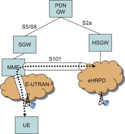
Figure 6.3.3.1 Terminal performing pre-registration in HRPD while being connected to E-UTRAN. The dashed line illustrates HRPD specific signalling transparently forwarded by E-UTRAN and MME.
The handover from HRPD to E-UTRAN is also performed with a preparation phase where E-UTRAN-specific signalling is exchanged between UE and MME via the S101 interface. This time the signalling is transported transparently via the HRPD access network. A difference with handover from HRPD to E-UTRAN is that the pre-registration/preparation takes place immediately prior to the terminal switches from HRPD to E-UTRAN radio, that is just before the actual handover is performed. There is thus no long-lived pre-registration state in target access in this case. For more details on the HO procedures between E-UTRAN and HRPD, please see Section 12.4.
6.3.4 Generic mobility between 3GPP and non-3GPP accesses
Generic mobility between heterogeneous access types, such as between a 3GPP access and WLAN or WiMAX, are also supported by EPS. Generic mobility is, as the name suggests, generic in the sense that the mobility procedures are not specifically adapted to any particular access technology. Instead the procedures are generic enough to be applicable to any non-3GPP access technology, such as WLAN and WiMAX, as long as the accesses support some basic requirements. The generic mobility procedures are, for example, also applicable for HRPD in case the optimized mechanisms described in the previous section are not deployed.
Since the generic mobility procedures are supposed to work with any access, they are also not optimized towards any specific access technology. In 3GPP and other standards fora, generic mobility is also referred to as non-optimized handover. However, a goal has still been to provide efficient HO procedures also in this generic case. In particular, for a terminal that is able to operate in multiple access technologies simultaneously – often referred to as ‘dual-radio capable’ terminals, it is possible to prepare the target access before performing the actual handover. The terminal can, for example, perform authentication procedures in target access while still using the source access to transfer user plane data. This is in a sense similar to the pre-registration described for HRPD with the difference that the ‘pre-registration’ is done in the actual target access instead of via the source access.
A key difference compared to the mobility mechanisms within and between 3GPP accesses and the optimized interworking between LTE and HRPD is that generic mobility does not assume any interaction between the two access networks. Instead the source and target access networks are fully decoupled.
The generic handover is always triggered by the terminal, that is, there are no measurements of cells in the target access being reported to the radio access network where the UE is attached. There are also no handover commands from the source access to trigger the handover. Instead it is up to the terminal to decide when to initiate the handover. The terminal may, for example, base its decision on measurement of signalling strength of available access networks. The operator may also use the Access Network Discovery and Selection Function (ANDSF) to provide the terminal with information about access networks as well as policies for access network selection. The ANDSF is described further in a following section.
The EPS supports two different mobility concepts for generic mobility between 3GPP and non-3GPP accesses; host- and network-based mobility. Host-based mobility is a term often used to denote a mobility scheme where the terminal (or host) is directly involved in the movement detection and mobility signalling. Mobile IP, defined by IETF, is one example of such a mobility protocol. In this case the terminal has IP mobility client software.
Another type of mobility protocol and mobility scheme is the network-based mobility management scheme. In this case the network can provide mobility services for a terminal that is not explicitly exchanging mobility signalling with the network. It is a task of the network to keep track of the terminal’s movements and ensure that the appropriate mobility signalling is executed in the core network in order for the terminal to maintain its session while moving. Proxy Mobile IPv6 (PMIPv6) is an example of a network-based mobility protocol. GPRS Tunnelling protocol (GTP) is another example of a network-based protocol that is used to support mobility.
EPS supports multiple mobility protocol options using host- and network-based mobility protocols. EPS supports two host-based mobility schemes; Dual-stack Mobile IPv6 (DSMIPv6) and Mobile IPv4 (MIPv4) over non-3GPP accesses. Over the 3GPP accesses host-based mobility is not used. Instead it is always assumed that the 3GPP access is the ‘home link’, in the host-based Mobile IP sense. Please see Section 11.3 for further descriptions of this and other Mobile IP concepts. Over non-3GPP accesses, it is also possible to use network-based PMIPv6 as was shown in Chapter 3. For 3GPP accesses, only network-based mobility protocols are used; either GTP or PMIPv6.
For a more detailed description of the mobility protocols and mobility mechanisms, see Chapter 11 for protocol descriptions and Chapter 12 for the details of the HO procedures.
Host- and network-based mobility schemes have different properties. A host-based scheme requires support for the mobility protocol in the terminal. Host-based mobility is often generic in the sense that it assumes nothing or very little about any particular access network. It can therefore be used also over those access networks not supporting mobility at all. A consequence is that basic host-based mobility is not optimized for any particular access network.
Network-based mobility on the other hand requires that the access network supports the mobility protocol. GTP, for example, is developed by 3GPP to support mobility between 3GPP accesses and includes support for context transfer and other features needed to provide a seamless handover within and between 3GPP accesses.
Even though the division between host- and network-based mobility schemes often provides a useful classification, it can be noted that in a complete system solution both host- and network-based mobility components are included. It is possible to handover from an access where host-based mobility protocol is used to an access where a network-based mobility protocol is used. Also with network-based mobility protocols, the terminals often need to be mobility aware and handle mobility even if they do not explicitly participate in the mobility signalling. Therefore, even though the division into host- and network-based mobility is a useful categorization on a high level and when discussing one specific protocol, it is also important to remember that in reality the full solution typically contains pieces of both. EPS supports different mobility protocols in different accesses and there may be change in mobility protocol when moving between access networks. The terminal may, for example, move from a non-3GPP access where DSMIPv6 is used to a 3GPP access where GTP or PMIPv6 is used. It is the task of the PDN GW to ensure that IP session continuity as provided also when different mobility protocols are used in the different accesses.
6.3.4.1 IP mobility mode selection
The EPS specifications allow both host- and network-based mobility; different operators may make different choices about which of the two to deploy in their networks. An operator may also choose to deploy both. In 3GPP accesses, there is only a choice between two network-based mobility protocols (PMIPv6 or GTP) and the selection of one protocol over the other has no impact on the terminal since the network choice of protocol is transparent to the UE. It should be noted that even if multiple mobility protocols are supported in a network deployment, only a single protocol is used at a time for a given UE and access type.
Terminals may support different mobility mechanisms. Some terminals may support host-based mobility and thus have a Mobile IP client installed (Dual Stack Mobile IPv6 and/or Mobile IPv4 client). Other terminals may support IP level session continuity where network-based mobility protocols are used. There may also be terminals that support both mechanisms. In addition, some terminals may neither have a Mobile IP client nor support IP session continuity using network-based mechanisms. These terminals will not support IP level session continuity but could still attach to EPC using different access technologies.
There is thus a need for selecting the right mobility mechanism when a terminal attaches to the network or is making a handover. If network-based mobility protocols are selected, there also needs to be a decision if session continuity (i.e. IP address preservation between the accesses) shall take place.
EPS has defined different means for how this selection can be done. The rules and mechanism for selecting the appropriate mobility protocol is referred to as IP Mobility Mode Selection (IPMS).
One option with IPMS is to statically configure the mobility mechanism to use in the network and the terminal. This is, for example, possible if the operator is only supporting a single mobility mechanism and if the operator can assume that the terminals used in its network supports the deployed mobility mechanism. If a user switches to another terminal not supporting the mobility protocol deployed by the operator, IP level session continuity may not be possible.
The other option is to have a more dynamic selection where the decision to use either network-or host-based mobility is made as part of attach or HO procedures. It should be noted that over 3GPP accesses only network-based mobility is supported using either PMIPv6 or GTP. Therefore, mobility mode selection is only needed when the terminal is using a non-3GPP access.
IPMS is performed when the user attaches in a non-3GPP access or sets up an IPSec tunnel towards an ePDG, before an IP address is provided to the terminal. The terminal may provide an indication about its supported mobility schemes during network access authentication by using an attribute in the EAP-AKA and EAP-AKA’ protocols, [24.302]. The indication from the UE informs the network if the terminal supports host-based mobility (DSMIPv6 or MIPv4) and/or if it supports IP session continuity using network-based mobility. The network may also learn about the terminal capabilities using other mechanisms. For example, if a terminal has attached in 3GPP access and performed bootstrapping for DSMIPv6, the network implicitly understands based on the already performed bootstrapping procedure that the terminal is capable of using DSMIPv6. Based on its knowledge about the terminal and the capabilities of the network, the network decides which mobility mechanism to use for the particular terminal. In case the network has no knowledge about a terminal’s capabilities, the default is to use network-based mobility protocols. Host-based mobility can only be selected by the network if it knows that the terminal supports the appropriate mobility protocol (DSMIPv6 or MIPv4).
6.3.4.2 Access network discovery and selection
The Access Network Discovery and Selection Function (ANDSF) is a server that has been defined in 3GPP TS 23.402, [23.402]. The ANDSF is a server in the network that provides the UE with policies and network selection information. The UE can query the server for information about other access networks; for example non-3GPP access networks, specifically it contains the data management and control functionality necessary to provision the discovery of different networks and selection procedures. These procedures are defined by the operator. Either the UE can request the information or the ANDSF can initiate the data transfer to the UE.
As depicted in Figure 6.3.4.2.1, the ANDSF function contains a reference point S14 to the UE to provide the UE with access network selection policies and/or access discovery hints.
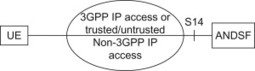
Figure 6.3.4.2.1 ANDSF architecture.
The information provided on the S14 interface can be used by the UE to understand which network to scan for and also the operator policies with regard to handover – for example whether to stay on 3GPP access or whether to perform the handover to another access network. Please see Section 10.11 for further details on ANDSF.
6.4 Idle Mode Signalling Reduction (ISR)
Idle mode signalling reduction is a feature that allows the UE to move between LTE and 2G/3G without performing Tracking Area (TA) or Routing Area (RA) update once ISR has been activated. As idle mode mobility between RATs may be rather common, especially in deployments with spotty coverage, ISR can be used to limit the signalling between the UE and the network as well as signalling within the network.
In 2G/3G there is also similar functionality which allows the UE to move between GERAN and UTRAN cells in idle mode without performing any signalling. This is implemented through using a common SGSN and common RAs; that is the GERAN and UTRAN cells belong to the same RA and can be paged for terminating events in both GERAN and UTRAN cells that belong to the RA.
It would have been possible to keep a similar concept for SAE but that would have required a combined SGSN/MME node. Due to this difference in architecture (SGSN vs. MME) and the area concepts (RA vs. list of TA), it was decided to implement the ISR functionality in a different way between E-UTRAN and GERAN/UTRAN than between GERAN and UTRAN.
The ISR feature enables signalling reduction with separate SGSN and MME and also with independent TAs and RAs. The dependency between EPC and 2G/3G is minimized at the cost of ISR-specific node and interface functionality.
The idea behind the ISR feature is that the UE can be registered in a GERAN/UTRAN RA at the same time as it is registered in an E-UTRAN TA (or list of TAs). The UE keeps the two registrations in parallel and run periodic timers for both registrations independently. Similarly the network keeps both registrations in parallel and it also ensures that the UE can be paged in both the RA and the TA(s) it is registered in.
6.4.1 ISR activation
A prerequisite for ISR activation is that the UE, SGSN, MME, Serving GW and HSS support ISR. The ISR support is specified to be mandatory for the UE but optional for network entities. ISR also requires an S4-SGSN, that is it is not supported with a Gn/Gp-SGSN.
At the first attach to the network, ISR is not activated. ISR can only be activated when the UE has first been registered in an RA on 2G/3G and then registers in a TA or vice versa.
If the UE first registers on GERAN/UTRAN and then moves into an LTE cell, the UE will initiate a TA update procedure. In the TA update procedure, the SGSN, MME and Serving GW will communicate their capabilities to support ISR, and if all nodes support ISR, the MME will indicate to the UE that ISR is activated in the TAU accept message.
A simplified example of a TA update procedure with ISR activation is shown in Figure 6.4.1.1. Before the TAU procedure is performed, the UE has attached in GERAN/UTRAN and have an active registration with an SGSN. There is hence an active MM context in UE, SGSN and HSS, and the SGSN has a control connection with the Serving GW.
-
In Step 1 the UE initiates a TAU procedure
-
In Step 2 the MME requests the UE context and indicates to the SGSN that it is ISR capable. The SGSN responds with the UE context and indicates that it supports ISR
-
In Step 3 the Serving GW is informed that the UE is registered with the MME and that ISR is activated
-
In Step 4 the HSS may be updated with the MME address. The update type indicates that HSS shall not cancel the SGSN location
-
In Step 5 the MME informs the UE that the TAU procedure was successful and that ISR is activated.
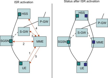
Figure 6.4.1.1 Outline of ISR an ISR activation procedure.
As shown in Figure 6.4.1.1, when ISR is activated, the UE is registered with both MME and SGSN. Both the SGSN and the MME have a control connect-ion with the Serving GW and the MME and SGSN are both registered in HSS. The UE stores MM parameters from SGSN (e.g. P-TMSI and RA) and from MME (e.g. GUTI and TA(s)) and the UE stores session management (bearer) contexts that are common for E-UTRAN and GERAN/UTRAN accesses. SGSN and MME store each other’s address when ISR is activated.
When ISR is activated, a UE in idle state can reselect between E-UTRAN and GERAN/UTRAN (within the registered RAs and TAs) without any need to signal with network.
6.4.2 Paging
When the UE is in idle mode and ISR is active and downlink data arrives in Serving GW, it will send a downlink data notification to both the MME and the SGSN. The MME will then initiate paging in the TA, where the UE is registered, and the SGSN will initiate paging in the RA, where the UE is registered. When the UE receives the paging message, it will perform a service request procedure on the RAT it is currently camping on. As part of the service request procedure, the Serving GW will be requested to establish a downlink data connection towards an eNodeB in case the UE was camping on E-UTRAN and towards the SGSN/RNC in case the UE was camping on GERAN/UTRAN. When the Serving GW receives this request to establish the downlink data connection, it will also inform the SGSN or MME to stop paging on the other RAT.
A simplified example of the paging procedure, when ISR is active and the UE camps on E-UTRAN, is outlined in Figure 6.4.2.1.
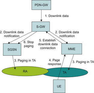
Figure 6.4.2.1 Simplified example of the paging procedure when ISR is active.
6.4.3 ISR deactivation
ISR activation has to be refreshed at every RAU and TAU procedure and the UE will deactivate ISR if it does not receive ISR active indication in the RAU accept and TAU accept messages.
The UE and the network run independent periodic update timers for GERAN/UTRAN and for E-UTRAN. The UE will perform RA update if it camps on GERAN/UTRAN when the periodic RAU timer expires and it will perform TA update if it camps on E-UTRAN when the periodic TAU timer expires. If the UE camps on a different RAT when the periodic timers expires, it will not perform the update procedure; for example, if it camps on E-UTRAN when the periodic RAU timer expires, it will remain camping on E-UTRAN and not perform a RAU update.
When the MME or SGSN do not receive periodic updates, the MME and SGSN may decide to implicitly detach the UE. The implicit detach removes session management (bearer) contexts from the node performing the implicit detach and it removes also the related control connection from the Serving GW. Implicit detach by one CN node (SGSN or MME) deactivates ISR in the network.
When the UE cannot perform periodic updates in time, it starts a Deactivate ISR timer. When this timer expires and the UE was not able to perform the required update procedure, the UE locally deactivates ISR.
ISR shall be deactivated by MME or SGSN, that is by omitting the signalling of ‘ISR activation’, when:
-
CN node change resulting in context transfer between the same type of CN nodes (SGSN to SGSN or MME to MME)
-
Serving GW change.
There are also situations where the UE needs to deactivate ISR locally, for example:
-
modification or activation of additional bearers
-
after updating either MME or SGSN about the change of the DRX parameters or UE capabilities
-
E-UTRAN selection by a UTRAN-connected UE (e.g. when in URA_PCH to release Iu on UTRAN side).
6.5 Identifiers and Corresponding Legacy IDs
Permanent and temporary subscriber identities are constructed to identify not only a particular subscriber but also the network entities where the permanent and temporary subscriber records are stored.
6.5.1 Permanent subscriber identifiers
Subscriptions (the USIM cards, the little piece of plastic you get from the operator) are identified with an IMSI (International Mobile Subscriber Identity). Each USIM card is assigned a unique IMSI. The IMSI is an E.164 number (basically a string of digits like a phone number) with a maximum length of 15 digits. The IMSI is constructed by an MCC (Mobile Country Code) and MNC (Mobile Network Code) and an MSIN (mobile subscriber identity) (Figure 6.5.1.1).
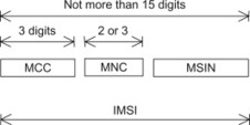
Figure 6.5.1.1 Structure of IMSI.
The MCC identifies the country and the MNC identifies the network within the country. The MSIN in turn is a unique number for each subscriber within a particular network.
The IMSI is the permanent subscription identifier and it is used as a master key in the subscriber database (HSS). By its construction it allows any network in the world to find the home operator of the subscriber, specifically it provides a mechanism to find the HSS in the home operator network.
The IMSI is also used in 2G/3G networks and there is no change of the purpose or format of the IMSI for SAE/LTE.
6.5.2 Temporary subscriber identifiers
Temporary subscriber identifiers are used for several purposes. They provide a level of privacy since the permanent identity does not need to be sent over the radio interface. But more importantly they provide a mechanism to find the resources where the subscriber’s temporary context is stored. The temporary context for the subscriber is stored in an MME (or SGSN in the 2G/3G case) and, for example, the eNodeB needs to be able to send signalling from a UE to the correct MME where the subscriber’s context resides.
Pooling of MMEs was an integral part of the SAE/LTE design (as opposed to 2G/3G where pooling was a feature added a few years after the original design). Hence the temporary identities in SAE/LTE could be designed with pooling in mind. This has resulted in a cleaner design of the temporary identities for SAE/LTE.
Figure 6.5.2.1 illustrates the temporary identifiers. The GUTI (Globally Unique Temporary ID) is a worldwide unique identity that points to a specific subscriber context in a specific MME. The S-TMSI is unique within a particular area of a single network. The UE can use the S-TMSI when communicating with the network as long as it stays within a TA that is part of the TA list it has received.
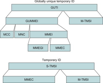
Figure 6.5.2.1 Structure of GUTI and S-TMSI.
The GUTI consists of two main components: (1) the GUMMEI (Globally Unique MME Identifier) that uniquely identifies the MME which allocated the GUTI and (2) the M-TMSI (MME Temporary Subscriber Identity) that identifies the subscriber within the MME.
The GUMMEI is in turn constructed from MCC (country), MNC (network) and MMEI (MME identifier, the MME within the network). The MMEI is constructed from an MMEGI (MME group ID) and an MMEC (MME Code).
The GUTI is a long identifier and to save radio resources, a shorter version of the GUTI is used whenever possible. The shorter version is called S-TMSI and it is unique, only within a group of MMEs. It is constructed from the MMEC and the M-TMSI. The S-TMSI is used for, for example, paging of UEs and service request.
One can imagine the different temporary identities, a set of pointers, to network resources in EPS (Figure 6.5.2.2).
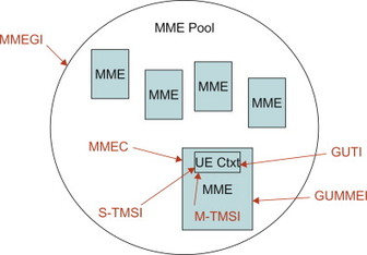
Figure 6.5.2.2 Identifiers as pointers.
6.5.3 Relation to subscription identifiers in 2G/3G
Why is there a need for a relation between the EPS and the 2G/3G identifiers? The main reason is mobility between GSM/WCDMA and LTE. When the UE moves from one access to the other, it should be possible to locate the node where the UE context is stored, for example, when moving to LTE the MME needs to find the UE context in the SGSN and vice versa. Another reason is that the implementation of combined SGSN and MME nodes will be available and it is preferable to map the temporary identifier used on LTE and the temporary identifier used on GSM/WCDMA so that they point to the same combined node.
The IMSI – the common permanent subscription identifier across GSM, UMTS and EPS – and the same subscription can be used to access all technologies.
The temporary identities in 2G/3G looks a little bit different, primarily since the original design of GSM/UMTS assumed a strictly hierarchical system where an RA was controlled by a single SGSN node. Hence the GSM/UMTS original design did not explicitly include any SGSN pool and SGSN node identifiers. When pooling was added in the GSM/UMTS system, these node identifiers were encoded inside the temporary identifier.
In GPRS the P-TMSI is the identifier that identifies the subscriber context inside an SGSN. The globally unique identifier in GPRS has no explicit name but by combining the RA ID (RAI) and the P-TMSI you get a globally unique identifier. The RAI is constructed by MCC, MNC, LAC and RAC.
Pooling is discussed in another chapter but the basic principle for pooling in 2G/3G is that the identities P-TMSI range is divided among the SGSNs in a pool. There are a set of bits inside the P-TMSI called NRI (Network Resource identifier) that points to specific SGSNs, and each SGSN in a pool is assigned one (or more) unique NRIs. The NRI in 2G/3G hence corresponds to the MME code and the NRI identifies as an SGSN in a pool just as the MME code identifies an MME in an MME pool.
The operator needs to ensure that the MMEC is unique within the MME pool area, and if overlapping pool areas are in use, they should be unique within the area of overlapping MME pools.
The GUTI is used to support subscriber identity confidentiality, and in the shortened S-TMSI form, to enable more efficient radio signalling procedures (e.g. paging and Service Request).
6.6 Pooling and Overload Protection
EPC was designed from the start with pooling of network elements as a foundation of the system, in contrast to 2G and 3G systems, where pooling was added as an afterthought. The pooling mechanisms in EPC are efficient for an operator’s network through allowing them to centralize and pool a group of their signalling nodes. It should be noted that the network elements are stateful; as a result the UE context is stored in every node involved in handling the UE.
In 2G and 3G networks, the core network was designed as a hierarchical system; when a terminal or UE was located in a particular cell, it was only able to connect to one Base Station (BS). While there was one-to-many relationships between the SGSN and Base Station Controller (BSC) and also between the BSC and BS, in practice, the UE was only able to be connected to one BS, BSC and therefore only one SGSN (Figure 6.6.1).
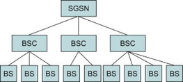
Figure 6.6.1 Original hierarchical system design for GSM/GPRS.
The same hierarchical structure applied in WCDMA networks for the Radio Network Controller (RNC) and node B. Naturally, this does not utilize the capacity of the nodes to their full potential; in the strictly hierarchical systems of the 2G and 3G networks, the capacity of the nodes can never be perfectly balanced; for example when users move in and out of cities. The network must be dimensioned according to the peak load in a particular area, which may be much higher than the average load in that area. Through applying a pooling mechanism, it is possible to dimension the whole pooled capacity to the peak rates of a much larger region; for example it is now possible to create a pool of network nodes for the entire London region, rather than the need to split the network up into many smaller regions.
So, how is this implemented in an actual network configuration?
As described in Section 6.5, an MME has several different identifiers associated with it, which help to manage the pooling mechanism. As a brief review, the MME Group identity refers to the name of the pool which the MME belongs to, while the MMEC identifies the actual node within a group; the MMEI is therefore formed by combining the MMEGI and MMEC together.
In LTE, the eNodeB knows which MMEs it can communicate with. When a terminal that is already registered enters a cell, it sends a service request to the network, which contains a GUTI, within which the MMEI is encapsulated. The eNodeB checks the GUTI code and if the MMEI is within the pool of MMEs for which it has a connection, it simply uses the MMEI to send it to the correct one. When a GUTI is available, therefore, it makes everything reasonably simple – the eNodeB can always route you to the correct MME. If the GUTI is absent, however, or the GUTI points to an MME that is not within the pool associated with that particular eNodeB, the eNodeB selects a new MME and forwards the service request to the new MME. The MME then returns a GUTI to the eNodeB which naturally includes its own MMEI.
The eNodeB cannot just randomly choose any old MME in the pool to send the service request to, however, because all of the MME nodes may have different capacities. Randomly allocating UEs to them, therefore may overload nodes with lower capacity. When configured, therefore, the MME is assigned a ‘weight factor’, which indicates its capacity. The MME then informs all of the eNodeBs in its pool what this weight factor is. The eNodeBs can therefore distribute UEs across the pool of MMEs accordingly.
There are certain situations where it may be useful to manipulate the weighting factor of an MME. Take the example of an already established pool of eNodeBs and MMEs that you wish to insert a new MME into. Initially that particular MME can inform the eNodeBs that is has a higher weight factor than it actual will during ‘normal’ operations. This means that the particular MME will then be allocated some UEs by eNodeBs. Once the new MME reaches a suitable load, it will update its weight factor and inform the eNodeBs of this change.
The implementation of pooling in the core network architecture also implies some changes with regard to network dimensioning. In the hierarchical systems, when you dimension your system, you will generally apply some general formula, for example peak load plus an additional 20% capacity in order to handle extra load. This is dimensioned across an area, however, not one particular region as with a pooled network architecture. This means that the numbers of subscribers that you are dealing with when calculating excess capacity are significantly different.
Take the example of a 3G system for which you are dimensioning a particular region for say a peak capacity of 100,000 users. Accordingly, you will dimension the nodes to handle peak capacity plus 20%, that is 120,000 subscribers for that particular area. When calculating across a region, however, the figures start to get a lot larger; for example 1,000,000 subscribers for say a big city; this implies a significantly larger ‘excess’ capacity needs to be factored in. However, this excess capacity is across many nodes, rather than across just a few. While the most natural thing when planning for redundancy in a pooled system would be to implement N + 1 nodes, where N is the number of nodes required for peak capacity of that region, since nodes can handle millions of users, the issue of the necessity of such a large cost may be raised. It is important, however, that there is capacity available in case a network node is to be taken out of service.