
Chapter 3 Architecture overview
This chapter introduces the EPS Architecture, firstly presenting a high-level perspective of the complete system as defined in the SAE work item. In subsequent sections, we introduce the logical nodes and functions in the network. By the end of this chapter, the main parts of the EPS architecture should be understandable and readers will be prepared for the full discussion about each function and interface, as well as all applicable signalling flows that follow in Parts III and IV.
3.1 EPS Architecture
There are several domains in EPS, each one a grouping of logical nodes that interwork to provide a specific set of functions in the network.
A network implementing 3GPP specifications is illustrated in Figure 3.1.1.
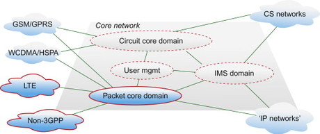
Figure 3.1.1 3GPP architecture domains.
On the left of the diagram are four clouds that represent different RAN domains that can connect to the EPC, including the second and third generations of mobile access networks specified by 3GPP, access networks, more commonly known as GSM and WCDMA respectively. LTE is of course the latest mobile broadband radio access as defined by 3GPP. Finally, there is the domain called ‘non-3GPP access networks’. This denotes any packet data access network that is not defined by 3GPP standardization processes, for example eHRPD, WLAN, fixed network accesses or some combination of these. This also means that 3GPP does not specify the details about these access technologies – these specifications are instead handled by other standardization fora, such as 3GPP2, IEEE or Broadband Forum. Interworking with these access domains will be covered in more detail in, Section 6.3.
The Core Network is divided into multiple domains (Circuit Core, Packet Core and IMS), as illustrated above. As can also be seen, these domains interwork with each other over a number of well-defined interfaces. The user management domain provides coordinated subscriber information and supports roaming and mobility between and within the different domains.
The Circuit Core domain consists of nodes and functions that provide support for circuit-switched services over GSM and WCDMA.
Correspondingly, the Packet Core domain consists of nodes and functions that provide support for packet-switched services (primarily IP connectivity) over GSM, WCDMA and HSPA. Furthermore, the Packet Core domain also provides support for packet-switched services over LTE and non-3GPP access networks which in general have no relation to the Circuit Core (except for some specific features needed for voice handovers in relation to LTE). The packet core domain also provides functions for management and enforcement of service and bearer level policies such as QoS.
The IMS domain consists of nodes and functions that provide support for multimedia sessions based on SIP (Session Initiation Protocol), and utilizes the IP connectivity provided by the functions in the Packet Core domain.
In the middle of all of this, there is also a user management domain, where resides the handling of the data related to the subscribers utilizing the services of the other domains. Formally, in the 3GPP specifications, it is not a separate domain in and of itself. Instead, there are user management functions in the Circuit Core, Packet Core and IMS domains interacting with subscriber data bases defined by 3GPP. However, for the purposes of clarity, we have selected to show this as a domain in and of itself.
The main emphasis here is the EPC architecture (defined within SAE work) which means the evolution of the Packet Core domain and user management domain. The development of LTE as a new 3GPP access technology is of course closely related to the design of EPC. Due to the importance of LTE in relation to EPC (since LTE only connects via Packet Core domain) we also provide a brief description of LTE on a high level. For a deeper insight into the interesting area of advanced radio communications called 3G Evolution, we recommend, [Dahlman, 2008]. The Circuit Core and the IMS domains are described in Chapter 5 where we look further on the topic of voice services.
We will now leave the high-level view of the 3GPP network architecture and turn our attention to the evolution of the Packet Core domain, or EPC.
While the logical architecture may look quite complex to anyone not familiar with the detailed functions of EPC, do not be put off. The EPS architecture consists of a few extra new functional entities in comparison to the previous core network architectures, with a large number of additional new functions and many new interfaces where common protocols are used. We will address the need for these additions and the perceived complexity by investigating all of these step by step.
Illustrated in Figure 3.1.2 is the logical architecture developed for EPS, together with the Packet Core domain defined prior to EPC. It also shows how the connection to this ‘old’ 3GPP packet core is designed (in fact, this specific connection comes in two flavours itself, a fact that adds to the complexity of the diagram, but more about that later).
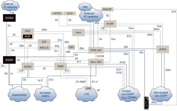
Figure 3.1.2 Architecture overview.
Note here that Figure 3.1.2 illustrates the complete architecture diagram, including support for interconnection of just about any packet data access network one can think of. It is unlikely that any single network operator would make use of all these logical nodes and interfaces; this means that deployment options and interconnect options are somewhat simplified.
What is not visible in the above diagram is the ‘pure’ IP infrastructure supporting the logical nodes as physical components of a real network. These functions are contained in the underlying transport network supporting the functions needed to run IP networks, specifically IP connectivity and routing between the entities, DNS functions supporting selection and discovery of different network elements within and between operators networks, support for both IPv4 and IPv6 in the transport and application layer (the layers are more clearly visible when we go into the details in Parts III and IV.
Be aware that all nodes and interfaces described in this chapter (and in fact, throughout the complete book) are logical nodes and interfaces, that is, in a real network implementation, some of these functions may reside on the same physical piece of infrastructure equipment; different vendors may have different implementations. In essence, different functions may be implemented in software and connect with one another via an internal interface, rather than via an actual cable. Also, the physical implementation of a particular interface may not run directly between two nodes; it may be routed via another physical site. Naturally, interfaces may also share transmission links.
One example is that the X2 interface connecting two eNodeBs (which will be explained in more detail later) may physically be routed from eNodeB A together with the S1 interface (which connects an eNodeB to an MME in the core network) to a site in the network with core network equipment. From this site, it would be routed back onto the radio access and finally to eNodeB B. This is illustrated in Figure 3.1.3.
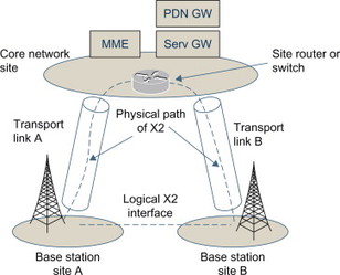
Figure 3.1.3 Logical and physical interfaces.
3.1.1 Basic IP connectivity over LTE access
At the core of the EPC architecture is the function required to support basic IP connectivity over LTE access. The plain vanilla EPC architecture, which one cannot live without when deploying LTE, appears as in Figure 3.1.1.1.
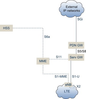
Figure 3.1.1.1 Basic EPC architecture for LTE.
Two main principles have been guiding the design of the architecture. First of all, the strong wish to optimize the handling of the user data traffic itself, through designing a ‘flat’ architecture. A flat architecture in this context means that as few nodes as possible are involved in processing the user data traffic. The primary motivation for this was to allow a cost efficient scaling of the infrastructure operating on the user data traffic itself, an argument increasingly important as mobile data traffic volumes are growing fast and are expected to grow even faster in the future with the introduction of new services relying on IP as well as new powerful access technologies such as LTE.
The second guiding principle was to separate the handling of the control signalling (shown as dotted lines) from the user data traffic. This was motivated by several factors. The need to allow independent scaling of control and user plane functions were seen as important since control data signalling tends to scale with the number of users, while user data volumes may scale more dependent on new services and applications as well as the capabilities in terms of the device (screen size, coder, etc). Allowing for both the control signalling functionality and the user data functionality to be implemented in optimized ways was another rationale for separating these functions in the logical architecture. A third important factor guiding the decision was that the split between control signalling and user data functions allowed for more flexibility in terms of network deployment as it allowed for the freedom of locating infrastructure equipment handling user data functions in a more distributed way in the networks, while at the same time allowing for a centralized deployment of the equipment handling the control signalling. This was in order to save valuable transmission resources and minimize delays between two parties connected and utilizing a real-time service such as voice or gaming. In addition to this, the split between the control signalling and user data functions allows for optimized operational costs through having these functions at separate physical locations in the network; through separating this functionality, the network nodes are more scalable in particular when it comes to supporting high-bandwidth traffic. Only those nodes that are associated with end-user traffic need to be scaled for the high throughput, rather than both the traffic and signalling nodes as would have been the case previously. Finally, the chosen architecture was similar to the existing packet core architecture for evolved HSPA, allowing the possibility of a smooth migration and co-location of functionality supporting both LTE and HSPA.
Looking at the architecture itself, let us start with the radio network. First of all, in the LTE radio network there is at least one eNodeB (the LTE base station). The functionality of the eNodeB includes all features needed to realize the actual wireless connections between user devices and the network. The features of the LTE eNodeB will be described in Chapter 10.
In a reasonably sized network scenario, there may be several thousand eNodeBs in the network; many of these may be interconnected via the X2 interface in order to allow for efficient handovers.
All eNodeBs are connected to at least one MME (short for the ‘Mobility Management Entity’) over the S1-MME logical interface. The MME handles all LTE-related control plane signalling, including mobility and security functions for devices and terminals attaching over the LTE RAN. The MME also manages all terminals being in idle mode, including support for Tracking Area management and paging. Idle mode will be further described in, Section 6.3.
The MME relies on the existence of subscription-related user data for all users trying to establish IP connectivity over the LTE RAN. For this purpose, the MME is connected to the HSS (the Home Subscriber Server) over the S6a interface. The HSS manages user data and related user management logic for users accessing over the LTE RAN. Subscription data includes credentials for authentication and access authorization, and the HSS also supports mobility management within LTE as well as between LTE and other access networks (more about this later).
The user data payload – the IP packets flowing to and from the mobile devices are handled by two logical nodes called the Serving Gateway (Serving GW) and the PDN Gateway (PDN GW) where PDN is short for ‘Packet Data Network’.
The Serving GW terminates the S1-U user plane interface towards the base stations (eNodeBs), and constitutes the anchor point for intra-LTE mobility, as well as (optionally) for mobility between GSM/GPRS, WCDMA/HSPA and LTE. The Serving GW also buffers downlink IP packets destined for terminals that happen to be in idle mode, as well as supports transport level QoS through marking IP packets with appropriate DiffServ code points based on the parameters associated with the corresponding packet bearer. (An in-depth description of how QoS works in the EPS architecture can be found in, Section 8.1.) For roaming users, the Serving GW always resides in the visited network, and supports accounting functions for inter-operator charging and billing settlements.
The PDN GW is the point of interconnect to external IP networks through the SGi interface. The PDN GW includes functionality for IP address allocation, charging, packet filtering and policy-based control of user-specific IP flows. The PDN GW also has a key role in supporting QoS for end-user IP services.
The Serving GW and PDN GW are connected over an interface called either S5 (if the user is not roaming, i.e. the user is attaching to his home network) or S8 (if the user is roaming, i.e. attaching to a visited LTE network).
Something quite unique with the EPC architecture is that one of the interfaces is specified in two different variants (you guessed correct – it is S5/S8). One of these variants utilizes the GTP protocol over S5/S8 (more about this in, Section 10.3), which is also used to provide IP connectivity over GSM/GPRS and WCDMA/HSPA networks. The other variant utilizes the IETF PMIPv6 protocol over S5/S8 (more about this in, Section 10.4).
Since PMIPv6 and GTP do not have exactly the same feature set, this means that the functional split between the Serving GW and the PDN GW is somewhat different depending on what protocol is deployed over S5/S8. In fact, nothing prevents both variants from being used simultaneously in one and the same network. This is not an unlikely situation since any operator deploying S5 based on the PMIPv6 variant may at least in the early years of LTE deployment have to rely on GTP over S8 since GTP is today the de-facto protocol used to interconnect hundreds of mobile networks world-wide, allowing for IP connectivity to be established just about anywhere in the world where there is GSM/GPRS or WCDMA/HSPA coverage.
Also note that S5 in itself may not be in use at all in most non-roaming traffic cases. It is a quite possible scenario that many operators will choose to deploy equipment that can combine Serving GW and PDN GW functionalities whenever needed, in practice reducing the amount of hardware needed to process the user data plane by 50%.
In some traffic cases, the S5 interface is however very much needed, resulting in a division of the Serving GW and PDN GW functionality between two physical pieces of infrastructure equipment (two ‘Gateways’). Note that for a single user/terminal point of view, there can only be a single Serving GW active at any given time.
The split GW deployment using S5 may happen in three cases:
-
When a user wants to connect to more than one external data network at the same time, and not all of these can be served from the same PDN GW. All user data related to the specific user will then always pass the same Serving GW, but more than one PDN GW
-
When an operator’s deployment scenario causes the operator to have their PDN GWs in a central location whereas the Serving GWs are distributed closer to the LTE radio base stations (eNodeBs)
-
When a user moves between two LTE radio base stations that does not belong to the same service area, the Serving GW need to be changed, while the PDN GW shall be retained in order not to break the IP connectivity. (The concepts of service areas and pooling will be described in detail in, Section 6.6)
Control plane signalling between the MME and the Serving GW is exchanged over the S11 interface which is one of the key interfaces in the EPC architecture. Among other things, this interface is used to establish IP connectivity for LTE users through connecting Gateways and radio base stations, as well as to provide support for mobility when users and their devices move between LTE radio base stations.
3.1.2 Adding more advanced functionality for LTE access
Expanding somewhat on the basic architecture described in above means introducing some more interfaces and some additional advanced features targeting the control of end-user IP flows; these additional features are covered in the following section.
For the purposes of this section, an ‘IP flow’ can normally be thought of as all IP packets flowing through the network associated with a specific application in use, e g a web browsing session or a TV stream.
See the architecture diagram in Figure 3.1.2.1, which shows a bit more detail than the previous illustration.
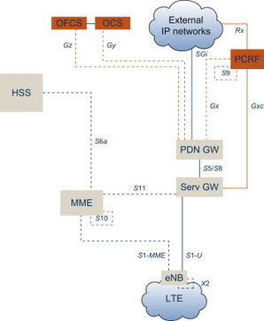
Figure 3.1.2.1 Adding policy control and charging support to the basic EPC architcture.
Three new logical nodes and associated interfaces are added – the PCRF, the OCS and the OFCS.
The PCRF (Policy and Charging Rules Function) make up a key part of a concept in the EPC architecture (and in the 3GPP packet core architecture in general) called PCC (Policy and Charging Control). The PCC concept is designed to enable flow-based charging, including, for example, online credit control, as well as policy control, which includes support for service authorization and QoS management.
What, then, is a ‘policy’ in the 3GPP architecture context? Think of it as a rule for what treatment a specific IP flow shall receive in the network, for example, how the data shall be charged for or what QoS that shall be awarded to this service. Both the charging and the policy control functions rely on that all IP flows are classified (in the PDN GW/Serving GW) using unique packet filters that operate in real time on the IP data flows.
The PCRF contains policy control decision and flow-based charging control functionalities. It terminates an interface called Rx, over which external application servers can send service information, including resource requirements and IP flow related parameters, to the PCRF. The PCRF interfaces the PDN GW over the Gx interface and for the case when PMIPv6 and not GTP is used on S5, the PCRF also interfaces the Serving GW over an interface called Gxc.
In the roaming case, a PCRF in the home network controls the policies to be applied. This is done via a PCRF in the visited network over the S9 interface which hence is a roaming interface between PCRFs.
OFCS is short for Offline Charging System while OCS is short for Online Charging System. Both logical entities interface the PDN GW (through the Gz and Gy interfaces respectively) and support various features related to charging of end-users based on a number of different parameters such as time, volume, event, etc., Section 8.3 contains a description of the charging support in the EPC architecture.
Also shown in the diagram above is an interface called S10. It connects MMEs together, and is used when the MME that is serving a user has to be changed for one reason or another, either due to maintenance, to a node failure, or the most obvious usage, when a terminal moves between two pools. Do not worry if this is not obvious to you – the pooling concept will be described in detail in Section 6.7.
3.1.3 Interworking between LTE and GSM/GPRS or WCDMA/HSPA
Given the fact that any new radio network is normally brought into service well before a complete radio coverage is achieved (if that ever happens), the ability to allow for a continuous service coverage through interworking with other radio networks is a key feature in any mobile network architecture. In many markets, LTE will be deployed in frequency bands around 2 GHz or higher. While the data capacity normally increases as one moves into higher frequency band (as there is more spectrum available), the ability to cover a given geographical area with a given base station output power quickly decreases with higher frequencies. Simply put, the gain in increased data capacity is unfortunately paid for by much less coverage, but that is simply the rule of physics.
For LTE deployment, interworking with existing access networks supporting IP connectivity hence becomes crucial. The EPS architecture is addressing this need with two different solutions. One is addressing GSM/GPRS and WCDMA/HSPA network operators, while the other solution is designed to allow LTE interworking with CDMA access technologies (1xRTT and eHRPD)., Section 6.4 includes more details on inter-system mobility support in EPC.
First of all, be aware of that there are several different ambition levels related to ‘interworking’.
The simplest way of interworking would be to allow for a portable device to connect to either LTE or, say HSPA, depending on specific preferences but also on the available radio coverage at the geographical location the user is at for the moment (assuming the user is carrying this ‘device’ which may be a portable laptop computer or similar). Let’s call this network A. When the user moves to another location, he or she is able to connect to another access network (B) if available. The change of access network from A to B is supported through one single service subscription, and may be more or less automated or hidden for the user. This is of course a quite basic level of support which means that services and applications running on the user device may not be usable when the device has moved; some of these will require an application restart. This is due to that when the user has moved and wants to use the new access network B, the network view this as a completely new attach request. The device is normally given a new IP address from the network, which then may or may not cause problems for the applications in use in the device. Furthermore, there is normally a quite long service interruption between loss of coverage of network A and the establishment of IP connectivity to network B. This is illustrated in figure 3.1.3.1.
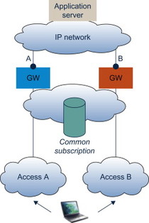
Figure 3.1.3.1 Inter-access mobility without session continuity.
This way of interworking basically only requires a single subscription allowing the end-user to attach over network A or network B, as well as that the user carries a portable device which includes support for both radio technologies. There is in fact no specific support required in the network itself, apart from the ability for the network operator to ensure the consistency of the user’s subscription data related to networks A and B respectively.
The EPC architecture however also allows for ‘session continuity’, that is that an IP connectivity session which is established over any of the allowed access networks (A or B) actually will survive movements between the different access networks due to loss of radio coverage. This is handled through retaining a stable ‘IP anchor point’ in the network which allows for not having to change the IP address of the device at all. Applications and services will, in theory, then not be dependent on the access network that is in use or on any possible movements between these. This is of course only partly true. Some services may rely on really high data speeds or very low network delay, criteria that may not be possible to meet with all of networks due to limited radio coverage or by limitations in the access technologies themselves. Remember that the wireless data performance and capabilities offered by LTE may be superior to HSPA which in its turn is vastly superior to GPRS, the IP connectivity service offered on GSM networks (Figure 3.1.3.2).
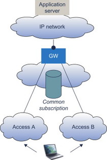
Figure 3.1.3.2 Inter-access mobility with session continuity.
This is however a point at which 3GPP has made the solution a bit more complex than what you could think was needed. 3GPP has in fact defined two different options for how to interconnect LTE and WCDMA/HSPA or GSM/GPRS. We will describe both below.
An important piece of understanding here is to note that when a terminal attaches over LTE it is served by the MME (as described above), whereas when the terminal attaches over a WCDMA/HSPA/GSM/GPRS network it is instead served by an SGSN.
The SGSN has been part of the packet core architecture since the first GSM/GPRS specification release in 1997. Back in those days, it was introduced to support a brand new service called GPRS which was and still is the packet data connectivity service of GSM. In 1999, the ability to also serve IP connectivity over WCDMA networks was added. Note that the IP connectivity service over WCDMA was greatly enhanced in 2005 through the definition of HSPA and the Direct Tunnel concept, but that has no real impact on the packet core architecture itself. HSPA is mainly an enhancement of the WCDMA radio access technology.
An SGSN connects to a GGSN which acts as the point of interconnect to external IP networks for all packet data sessions over GSM/GPRS and WCDMA/HSPA. In fact, it is the SGSN that selects which GGSN to use for a specific terminal.
When a user is moving between two networks that happen to be served by two different SGSNs, these SGSNs interact over an interface (quite illogically also called Gn) to support IP session continuity, that is, that the IP address, and all other data associated with the IP session itself, is maintained through keeping the GGSN unchanged when changing from one access network to the other.
If we disregard physical packet data equipment which may or may not have smooth migration paths to the EPC architecture, the logical SGSN node has a key role to play also for LTE, but that is however not the case for the logical GGSN node. Below we will show you why this is the case.
The legacy packet core architecture and control signalling procedures form the base for the first solution for interworking between LTE and GSM/GPRS or WCDMA/HSPA described here. It was actually the second one defined but it is the most straightforward to understand.
This solution includes the SGSN attaching to GSM and WCDMA radio networks as today, but then includes the MME and the PDN GW acting as an SGSN and a GGSN respectively. The MME and PDN GW are in fact replicating the signalling needed for movements between networks GSM/GPRS and WCDMA/HSPA to also apply for mobility with LTE (Figure 3.1.3.3).
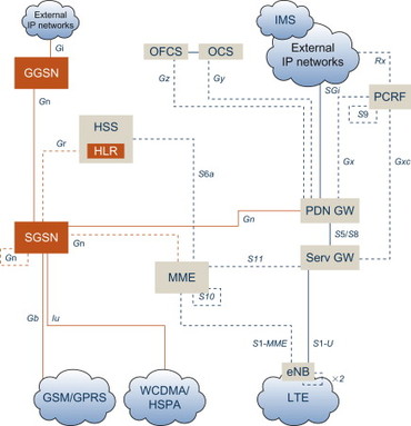
Figure 3.1.3.3 Interworking between LTE and GSM/GPRS or WCDMA/HSPA.
This includes both the MME and the PDN GW interfacing the SGSN over the standard packet core Gn interface. It may even be a Gn interface with an older date, that is specified and in operation prior to EPC being designed. This latter case is referred to as a pre-Rel8-SGSN.
In order to get this solution to work, a few key functions are needed.
First of all, the SGSN must be able to distinguish between a terminal that attaches over GSM/GPRS or WCDMA/HSPA but is not capable of moving to LTE, from a terminal that in fact can connect to LTE but is currently attaching to GSM/GPRS or WCDMA/HSPA due to lack of LTE radio coverage. The latter terminal must always be using the PDN GW as the anchor point and never a GGSN since there is no logical connection between the LTE radio network and a GGSN. If such an incorrect choice of IP anchor point would be made, IP sessions would be dropped when changing access network to LTE.
See the example in Figure 3.1.3.4; terminal A has GSM/WCDMA support but is not capable of utilizing LTE access, while terminal B can use all three RANs.
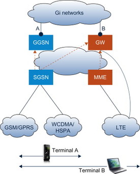
Figure 3.1.3.4 SGSN selection of GW.
The simplest case is when terminal B attaches to an LTE radio network. It is then served by the MME which will select a PDN GW and Serving GW (in the figure collectively referred to as ‘GW’).
When either of the terminals attach over GSM or WCDMA radio it is served by the SGSN. For terminal B this may happen when there is no LTE coverage, while terminal A does not have LTE support so the LTE coverage situation is then irrelevant.
The SGSN may use different ways of choosing either a GGSN or a PDN GW as an IP session anchor point for a terminal, but the most obvious way is to utilize the ‘APN’ (Access Point Name), which is a part of the configuration data related to a user subscription and is pointing at the preferred external network. Since only terminals which include LTE radio access support (terminal B in the example) may ever move and attach to an LTE RAN, the simplest solution is to make sure that only these subscriptions are configured with an APN that is associated with a PDN GW. This helps the SGSN in taking a correct decision and ensuring the terminal B is using the PDN GW and not the GGSN as the IP anchor point.
The other important part of the solution is to provide a single (or at least consistent) set of user and subscription data. Traditionally, the SGSN has interfaced a logical node called HLR (Home Location Register) which is the main database for user data in GSM and WCDMA. This interface is called Gr. The MME instead interfaces the HSS (Home Subscriber Server) as described above. When moving between GSM/WCDMA and LTE, there must not be inconsistent information in the network about, for example, to what network (A, B or C) a specific terminal is currently attached. This means that the HLR and HSS need either to share a single set of data, or to ensure consistency through other means such as close interaction between the two network functions. 3GPP does not specify any detailed solution to this problem. In fact, the 3GPP specification avoids the problem through defining HLR as a subset of HSS in later versions of the standards. As for the actual solution of ensuring this data consistency, it varies between different vendors of network infrastructure equipment.
However, as you know from above, this is not the only solution for interworking between LTE and GSM/GPRS/WCDMA/HSPA. In fact, 3GPP first defined another solution. This is described in (Figure 3.1.3.5).
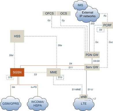
Figure 3.1.3.5 Interworking using GTPv2 interfaces.
Just like the first interworking architecture described, this solution naturally also includes an SGSN interfacing the GSM/GPRS and WCDMA/HSPA radio networks using the Gb and Iu-PS interfaces. So far there are no major differences.
Then however, the SGSN implements four new interfaces. Three of these (called S3, S4 and S16) rely on an updated version of the GTP protocol, the protocol that has been used since the old days of GPRS in the late 1990s, and which forms a core part of the 3GPP packet core architecture. All three are used instead of the different variants of the Gn interface present in the ‘legacy’ packet core architecture. The fourth new interface is S6d which mimics the MME S6a interface towards the HSS for retrieving subscriber data from the HSS, but for the SGSN it is naturally data related to GSM and/or WCDMA, not to LTE. Just as with S6a, the IETF Diameter protocol is used also over S6d, eliminating the need for the SGSN to support SS7/MAP signalling towards the HLR.
S3 is a signalling-only interface. It is used between the SGSN and the MME to support inter-system mobility. S16 is the SGSN-SGSN interface, while S4 is connecting the SGSN and the Serving GW. Note that here is a difference compared to the other solution where the SGSN interfaces the PDN GW and treats this like a GGSN.
Connecting the SGSN with the Serving GW creates a common anchor point for LTE, GSM/GPRS and WCDMA/HSPA in the Serving GW. Since the Serving GW for all roamers is located in the visited network, this means that all user traffic related to one roaming user will pass through this point in the network, regardless of which radio network that is being used. This is new and a difference to how roaming is handled in the old solution where the SGSN itself implements the roaming interface for GSM and WCDMA and the Serving GW only for LTE. With all roaming traffic instead passing through a single point in the network, it allows for the visited network operator to control and monitor the traffic in a consistent way, potentially based on policies. One potential drawback is that user traffic need to pass through one additional network node on its way to the PDN GW, but there is a solution to that, at least for WCDMA/HSPA. This is to utilize a direct connection between the Radio Network Controller (RNC) in the WCDMA radio network and the Serving GW. This interface is called S12, is optional, and if used, it means that the SGSN will only handle the control signalling for WCDMA/HSPA. The primary driver for this is that the network does not have to be scaled in terms of SGSN user capacity as well, important due to the expected large increase of data sent over wireless networks. See Figure 3.1.3.6.
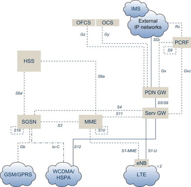
Figure 3.1.3.6 Direct tunnel support for WCDMA/HSPA.
It should be noted that this ability to let the user data bypass the SGSN is in fact also possible with the first solution. This means that the WCDMA RNC directly would interface the PDN GW for the user traffic connections. A difference is that this would not work for roamers since as stated above, roaming traffic here always pass through the SGSN.
A further benefit of utilizing S3/S4 from the SGSN instead of Gn is that the 3GPP specifications then allow for optimization of the signalling load for all terminals in idle mode. This concept is called ISR (short for Idle Mode Signalling Reduction) and will be explained in detail in, Section 6.4.
3.1.4 Interworking between LTE and CDMA networks
As stated above, an important part of the objectives behind the creation of EPC has been to allow an efficient interworking with legacy mobile network infrastructure in order to allow for wide area service coverage. As there was significant interest towards using a common EPC that was being developed in 3GPP under the SAE framework, strong efforts were devoted to design a solution linking LTE and the CDMA technologies defined by 3GPP2, allowing for efficient and smooth handovers between the different technologies as the differences in radio coverage require.
Figure 3.1.4.1 shows the EPC solution for LTE-eHRPD interworking.
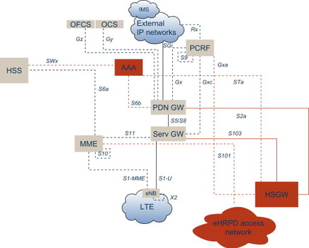
Figure 3.1.4.1 Interworking between LTE and eHRPD networks.
It includes the emergence of the eHRPD network, depicted by the darker entities. It shall be noted that this picture excludes all details of the CDMA network itself other than what is relevant for the SAE framework for EPS. In fact, just as with 3GPP networks, there are more than one flavour of CDMA networks – the voice + data network normally referred to as 1×RTT and the data only eHRPD are the two CDMA technology that EPS provides interworking with.
A number of additional interfaces are needed in the EPS architecture to allow LTE-CDMA interworking. Three of these (called S101, S102 and S103) are unique for CDMA networks and used to provide optimal performance during handover, whereas the other three (S2a, Gxa and STa) are generic and may be used for any non-3GPP access interworking, not only with CDMA networks. We will describe these interfaces below.
A fundamental function for allowing efficient interworking between two access technologies is to enable a common set of subscription data to be used – both for authentication purposes as well as for keeping track of which network the user is currently attached to. The core of the solution is to allow for the HSS to act as the common data base for all subscription data. Access authentication for a user attaching over an eHRPD network are handled using 3GPP2 mechanisms which are based on IETF AAA functionality. (AAA is short for Authentication, Authorization and Accounting). For this purpose, the eHRPD network is connected to the EPC architecture over the STa interface. It is terminated in a logical node called the 3GPP AAA Server, which in real-life implementations either may be a software feature inside the HSS or stand-alone AAA equipment interfacing the HSS over the Diameter-based SWx interface. Note that 3GPP already used the AAA mechanism for authentication and authorization before EPS due to interworking solutions for WLAN developed prior to the SAE work.
The PDN GW interfaces the 3GPP AAA Server over the S6b interface. This interface is used by the PDN GW to retrieve certain subscription data. It is also used to store the information regarding the PDN GW the user is connected to, this in order to secure that when the user moves and attaches over LTE, the MME shall be able to select the same PDN GW as was used for eHRPD network, which is a pre-requisite for maintaining the IP session also after the handover.
The PDN GW acts as the common IP anchor point also for users attached over the eHRPD network. The user data between the eHRPD Serving Gateway (HSGW) and the PDN GW are transported over the S2a interface which implements the PMIPv6 protocol, specified by IETF to support intra-network mobility.
The EPC architecture also allows for a common policy controller (the PCRF) to apply policies also in the eHRPD network. This is done over the Gxa interface to the HSGW.
In addition to these core interfaces for the LTE-eHRPD interworking, there are three more interfaces specified. Two of these are used to optimize the handover performance for eHRPD data, while the third is used to support voice services in 1xRTT. This last interface, called S102, will not be further described here, but rather in the section on voice support below.
The S101 interface is used when a packet data handover between LTE and an eHRPD network is to take place. Before the handover itself, the terminal pre-registers in the target network to prepare this network for the handover and thus reduce the perceived interruption time. This pre-registration as well as the actual handover signalling is carried over the S101 interface between the MME and the eHRPD access network. This is described in more detail in, Section 6.3.
To further optimize the packet data handover performance between LTE and eHRPD, there is also an S103 interface specified. This is an interface used to forward any IP data packets destined to the terminal that happened to end up in the Serving GW while the user terminal was executing the handover to eHRPD. These packets can then be forwarded to the HSGW in the eHRPD network, thus achieving close to a true loss-less handover performance. The value of this packet forwarding depends on the actual application in use. It can be seen as an optional optimization which may add value in some use cases.
3.1.5 Interworking between 3GPP access technologies and non-3GPP access technologies
The EPC architecture has been designed to allow interconnection with just about any access technology. This creates a common way of treating access to a PDN regardless of the access technology used, meaning that, for example, terminal’s IP address assignment, access to general IP services as well as network features like user subscription management, security, charging, policy control and VPN connections can be made independent of the access technology – be it wireless or fixed (Figure 3.1.5.1).
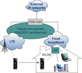
Figure 3.1.5.1 Interworking between 3GPP access and non-3GPP access technologies.
Besides the common and access-independent feature set for service treatment, the architecture also allows for interworking between 3GPP technologies (i.e., GSM/GPRS, WCDMA/HSPA and LTE) and non-3GPP technologies (e.g., CDMA (as described above), WLAN or a fixed access technology).
Think of this as a use case: you carry a device which can access among other technologies, LTE and WLAN. You are connected to the LTE/EPC network and move indoors, into your house. There you have a fixed broadband connection connected to a WLAN-capable home router. Depending on preferences, the device may in this situation switch access from LTE to WLAN. The EPS network then includes features to maintain the sessions also during this handover between two quite different access technologies.
The key functionality desired is support for mobility in the PDN GW. Mobile IP was designed in the 1990s by the IETF to provide IP host mobility, which is the ability for a portable computer to connect to a visited IP network, and establish a connection to the home IP network through tunnelling of IP packets. To all corresponding hosts, this computer would appear as still being in the home network. Mobile IP technology has since been used to provide mobility for packet data services in mobile networks based on CDMA technology.
Due to the diversity of the requirements when specifying the SAE framework, this part has (somewhat unfortunately) come out with quite a few options. First of all, either ‘Client-based’ or ‘Network-based’ Mobile IP can be used. Client-based means that the Mobile IP client resides in the terminal, and that IP tunnels are established between the terminal and the PDN GW across the access network. Network-based means that there are functions in the access network that acts on behalf of the terminal, and provides mobility support.
The major advantage with a Client-based approach is that it may work over any access network, as long as there is adequate support in the terminal itself. This function may be used totally transparent to the functionality in the access network. The advantage with a Network-based approach is the opposite – it simplifies the terminal client application, but instead requires that there is specific Mobile IP support in the network itself. eHRPD is one access network where the latter approach has been chosen, as described above. One of the key concerns with ‘Client-based mobility’ was how secure, trusted and efficient such mobility would be. These concerns partly drove the development of the Network-based mobility track in 3GPP and in IETF.
The parts of the EPC architecture that apply to the ‘non-3GPP’ access support are shown in Figure 3.1.5.2. As can be seen, there are multiple ways to interconnect to a non-3GPP access network.
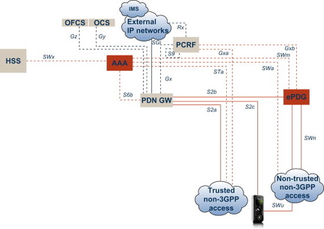
Figure 3.1.5.2 EPC architecture for non-3GPP accesses.
There are two ways to distinguish between the available options:
-
Is it a connection to ‘trusted’ or a ‘non-trusted network’?
-
Are ‘Network-based’ or ‘Client-based’ mobility mechanisms used?
Network-based and Client-based concepts were described above, so what is then a ‘trusted’ and a ‘non-trusted’ access network? Simply put, this is really an indicator on if the 3GPP operator (owning the PDN GW and the HSS) trust the security of the non-3GPP access network. A typical ‘trusted’ network may be an eHRPD network, while a ‘non-trusted’ network may be, for example, usage of WLAN in a public café and connecting to the PDN GW over the public Internet.
The S2a, STa and Gxa interfaces were described above for eHRPD and also apply in this context in the same manner. STa and Gxa apply to any trusted non-3GPP access network, and are used for user data and policy control respectively. S2a is used for data connectivity when Network-based mobility schemes are used in combination with trusted networks.
The corresponding interfaces for non-trusted networks are S2b, SWa (not STb) and Gxb. There is however a major difference here. Since the operator may not trust the non-3GPP access network that is used by the device when attaching, the S2b and Gxb interfaces do not interface the access network itself, but instead a new logical node called the ePDG (evolved Packet Data Gateway). This is an evolution of the PDG that is specified in earlier versions of the 3GPP standards to allow interconnection (but not inter-access mobility) of WLAN access to a 3GPP network. Typically, the ePDG belongs to the mobile operator. More information on this can be found in, Section 7.3.
Encrypted tunnels are established between the user devices and the ePDG, to ensure that each device can communicate with the network in a secure way. This creates a logical association between the device and the ePDG, referred to as the SWu interface, which both carries signalling needed for management of the tunnel itself, as well as carrying the data. The ePDG then connects to the PDN GW, and data as well as signalling is transferred using the S2b interface between these two nodes. The ePDG also interfaces the PCRF over Gxb to support policy control mechanisms (details of this specific part of the EPC architecture is however not yet defined by 3GPP).
The interface between the non-trusted access network and the ePDG is called SWn. It carries all signalling and data between the two networks – the non-trusted access, and the operator network to which the ePDG belongs. SWu traffic and signalling is hence always routed over the SWn interface.
One final interface to understand in this non-3GPP access solution is SWm. This is a signalling-interface only, and connects the ePDG to the AAA Server. It is used to transport AAA-related parameters between the AAA server (which in itself may get the data from the HSS) and the ePDG, in order to support setup and authentication of the IPsec tunnels between the ePDG and the terminal.
In addition to the Network-based mobility solutions for trusted and non-trusted networks, there is also the Client-based mobility solution which relies on the S2c interface between the mobile device and the PDN GW. This means that an overlay solution is created which does not require any specific support from the underlying non-3GPP access network.
Client-based and Network-based mobility solutions are further discussed in Section 6.3 and Section 11.3.
3.1.6 Support for voice services
In addition to the primary focus on enabling an efficient Mobile Broadband solution, the support for voice services was also given high priority in the 3GPP SAE specification work. From the start, it was however agreed that LTE is a packet-only access network, allowing an optimization for packet services. Since the voice services so far have been realized using circuit-switched technologies, this meant that specific mechanisms were introduced to also allow for voice services for users of the packet data services offered over the LTE access., Section 5.2 explains the subject of voice for LTE in more depth. In this chapter, we want to highlight the applicable parts of the architecture.
Shortly, the two main solutions for voice are to either use the IMS mechanisms and realize voice using the MultiMedia Telephony (MMTel) framework, that is using voice-over-IP, or to stick to the ‘old' circuit-switched way of providing voice services. The second option is in 3GPP specifications realized through that users temporarily leave LTE to perform the voice calls over 2G/3G, and then return when the voice call is finished. This may not be the most elegant of solutions, but can be seen primarily as a gap-filler in case IMS infrastructure is not in place.
When a user engaged in an IMS/MMTel voice call moves around, it is not unlikely that the user device may encounter that the LTE radio coverage is being lost. After all, this is a mobile system, and this of course may happen frequently depending on how users move around. For this purpose, 3GPP specified mechanisms to hand over an ongoing voice call in IMS/MMTel. What happens then depends on whether the new (target system) can support IMS/MMTel or not. If this is the case, this will be solved through a packet handover procedure (see Section 12.4) and the IMS/MMTel session will continue after the handover. If this is not the case, the IMS/MMTel session will be handed over to a circuit-switched call in GSM, WCDMA or 1xRTT. To achieve a smooth handover, this procedure involves pre-registration of the terminal in the target system CS domain (i.e., the system that the terminal will be attached to instead of LTE after the handover) and an efficient handover signalling.
If no IMS is present in the network at all or LTE users have to temporarily leave LTE during voice calls as described above, the MME interacts with the circuit-switched infrastructure to achieve this temporary suspension of the LTE services.
Figure 3.1.6.1 highlights the parts of the architecture that applies to voice handovers. Note that this diagram shows the GSM/WCDMA MSC Server and its interfaces to the GSM and WCDMA network. These connections are not included in the overall diagram shown at the beginning of this chapter, purely in order not to make the diagram even more complex.
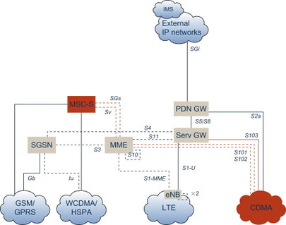
Figure 3.1.6.1 EPC architecture for voice support.
The case of a packet handover to GSM/WCDMA is supported using handover signalling over the S3 (or Gn) interface between the MME and the SGSN. The corresponding interface for CDMA is called S101 and connects the MME to the RNC used for eHRPD. In order to further optimized the packet handover performance, packet forwarding may be used (it is optional). This means that any packets destined for the user device that may have happened to have been sent ‘downwards’ from the PDN GW (to either the SGSN, Serving GW or eHRPD HSGW) may be forwarded to the corresponding node in the target system. This is not absolutely required, but may improve the user experience of a handover, since in theory no data need to be lost during the handover. The case of packet forwarding between LTE and GSM/WCDMA is supported over Gn/S4 between SGSN and Serving GW, whereas the case of LTE-eHRPD packet forwarding is supported over the S103 interface between the Serving GW and the HSGW.
In the case MMTel is not supported by the target network, there are also functions for handing over an IMS-based MMTel session to a circuit-switched voice call in GSM, WCDMA or CDMA 1×RTT. This handover is realized through procedures executed over the Sv interface between the MME and the MSC Server (for GSM and WCDMA) or the S102 interface between the MME and the 1×RTT MSC. This procedure is known as ‘Single-Radio Voice Call Continuity’ (SRVCC).
Finally, support for always falling back to circuit-switched calls even when in LTE coverage (which means that no IMS infrastructure is used) is supported through signalling over the SGs interface between MME and a GSM/WCDMA MSC Server or over the S102 interface connecting the MME to an 1×RTT MSC. This procedure is known as ‘Circuit-Switched Fallback’ (CSFB).
3.1.7 Miscellaneous features
We are almost through this overview of the 3GPP EPS architecture developed under the SAE work umbrella, including all the logical network nodes and the interfaces. As a final part, let us look at three distinct features in the architecture that may be seen as somewhat outside the core of the architecture (Figure 3.1.7.1).
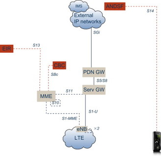
Figure 3.1.7.1 Miscellaneous features in the EPC architecture.
The first of these functions is called ETWS. This is short for Earthquake and Tsunami Warning System and is considered an important safety feature for countries endangered by nature catastrophes. Simply it means that a warning is received by the Cell Broadcast Centre (CBC) from, say, a government agency monitoring seismic activity and predicting earthquakes. The CBC interfaces the MMEs in the network over the SBc interface. Since all terminals in the network must be reachable for this warning, the MMEs must convey the warning to all terminals that happen to be in idle mode, and whose location is only known with the accuracy of a Tracking Area which may or may not contain lots of base stations and radio cells.
Another feature is the support for the Equipment Identity Register (the EIR) which is optionally used by the MME when a user attaches. The EIR is a database that contains information regarding whether the device used to attach to the network happens to be stolen or not. If that is the case, the MME can reject the attach attempt. The MME interfaces the EIR with the S13 interface.
The final function in the architecture is the ANDSF entity. ANDSF is short for Access Network Discovery and Selection Function, and put simply, it is a function in the network that the operator can use to control how users and their devices prioritize between different access technologies if several non-3GPP access networks are available. It is a means to give the network operator the possibility to control how users attach to the network, based on a number of criteria. The ANDSF logical entity, which interfaces the user device over an interface called S14, will be further described in, Section 6.3.
3.1.8 Summing up the architecture overview
The purpose of the description above was to make the overall EPS architecture a bit more comprehensive and understandable. When putting all the pieces back together, we arrive at the complete architecture diagram as shown in the beginning of this chapter (Figure 3.1.8.1).
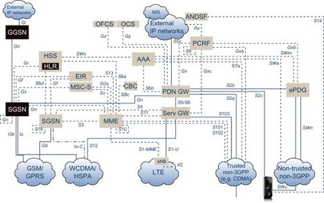
Figure 3.1.8.1 EPC architecture overview.
Large parts of the remainder of this book are devoted to describe each of the network elements (or nodes), each of the interfaces and each of the functions in greater detail.
3.2 Mobile Devices
This is not a book intending to describe end-user devices in any detail, but in order to understand some of the features and functions included in the EPC, a basic understanding of the capabilities and limitations of the end-user devices is beneficial.
The terms ‘Terminal’, ‘End-User Terminal’, and ‘User Equipment (UE)’ are all used to denote the actual device communicating with the network. Depending on what type of device this is, there may or may not be a human user utilizing the device, and the device may or may not be moving between the cells in the network. Does this sound strange? It will be further elaborated upon below.
3.2.1 Different types of devices
Examples below show devices supporting WCDMA/HSPA and/or GSM/GPRS. The first generation of LTE devices are data modems possible to attach to standard portable computers, sometimes called USB dongles. Over time, devices supporting LTE can be expected to have similar form factors as all of the devices shown below.
Most people would probably associate a ‘mobile device’ with a mobile phone. This is by far the most common type of end-user device today, and they have been around in at least portable form factors since the 1980s. Today they count in billions and come with different forms and features.
From the start, mobile phones have been designed for voice services, and over time more service capabilities have been added, primarily SMS support as well as e-mail and web surfing.
This is specifically the case for advanced mobile phones, sometimes referred to as Smartphones, which in many cases also include more advanced means for text entry, for example, through a full QWERTY keyboard or through pressure-sensitive screens in combination with hand-writing recognition techniques.
Another type of device that is rapidly increasing in numbers is portable computers equipped with wireless communication support. This can either be standard portable computers to which is added an external modem, connected, for example, over USB, or portable computers which are shipped from factory with built-in support for mobile broadband services. It goes without saying that portable computers of course are very suitable devices for users of data services. It can however be assumed that users of portable computers are on average somewhat less mobile than users of mobile phones. Usage of laptop computers is more common in, for example, a café or in the summer house than in a car, affecting the mobility patterns to some degree.
Also emerging with capabilities and form factors in between Smartphones and portable computers are a group of devices called Mobile Internet Devices (MIDs), which are physically larger than a normal mobile phone but smaller than a laptop. MIDs come with advanced communication capabilities and relatively high processing power and are typically equipped with a large screen for touch-sensitive usage, sometimes in combination with a normal keyboard.
Yet another type of device is the so called ‘Fixed Wireless Terminal’. This is a device which is not intended to be carried around, but instead installed permanently in, for example, a private house. A fixed wireless terminal connects to the surrounding world through the mobile network, at the same time as providing standard Ethernet LAN or Wireless LAN connections to the home network. This device can then be used to deliver similar services to the home as is possible with fixed broadband services over copper cables. Fixed Wireless devices and services may be used by mobile operators both to compete with fixed broadband operators as well as to provide broadband services in geographical areas without copper or fibre cabling. Naturally, Fixed Wireless Terminals normally do not move around in the network, reducing the overall signalling load related to handovers.
Yet another type of devices are terminals which are not for usage by or interaction with human users, but instead designed for machine-to-machine (M2M) communications. These devices may come in a wide range of very different form factors, and only the human imagination itself may limit the usage areas. Examples on usage cases for such devices are:
-
Built into private cars for communicating service needs, the car’s position (retrieved using GPS) as well as receiving up-to-date traffic data for traffic guidance systems
-
Built into water or electricity meters for remote control and/or remote meter reading
-
Built into street-side vending machines for communicating when goods are out-of-stock or when enough coins are present to justify a visit for emptying
-
Built into taxi cars for validating credit cards
-
Built into delivery cars for fleet management including optimization of delivery routes and confirming deliveries
-
Built into ambulances for sending life-critical medicine data to the hospital prior to arriving in order to increase chances of successful treatments
-
Built-into surveillance cameras for home or corporate security purposes.
As said, only the human imagination sets the limits for how wireless communications can be used to enhance business systems or to increase efficiency and security.
Finally, another type of device that is likely to include communication capabilities in the future is digital cameras including video cameras. Photos or films that have just been captured can easily be transferred to the network for backup and storage or for sharing with family and friends. This is not mobile phones with built-in cameras, this is instead cameras with built-in communication capabilities.
3.2.2 Terminals becoming general-purpose devices
A general trend is that more and more ‘add-on’ functionality is built into mobile phones (including Smartphones) turning these into general-purpose devices. This is functionality that goes beyond the actual communication services, and examples include:
-
Media players (MP3 for music, MP4 and other formats for video)
-
Camera functionality (photos and video recording)
-
FM radio receiver
-
GPS receiver for positioning using satellite systems
-
Games
To some extent these features may remove the need to carry separate devices such as a digital camera and a music (MP3) player, and some of this is functionality that may be used to generate (photo or video camera function) or consume (music and media player) large amounts of data. Since the resolution and quality of integrated cameras and screens are steadily increasing, as is the memory capabilities of mobile phones, the amount of data managed in the device rapidly increases as well. Some of this data may be downloaded to or uploaded from the device.
There are multiple options for how to get this increasing amount of data into and out from the mobile device. Options include:
-
Sending and receiving over the mobile network, for example receiving video streams being part of mobile TV broadcasting, or sending a newly taken photo using a mobile messaging service
-
Sending and receiving the data over an alternative access such as WLAN which is supported in more or less 100% of portable computers and is becoming increasingly common in mobile phones
-
Downloading and uploading using USB or Bluetooth when connecting to a PC
-
Transferring through physically moving a memory card between the mobile phone and a card reader connected to a PC.
Mobile broadband solutions based on HSPA or LTE are optimized to support efficient data transfer to devices regardless of physical location (that is, as long as there is sufficiently good radio coverage).
3.2.3 Some challenges
There are a number of challenges to address for designers of mobile devices. Some of the most important ones are briefly discussed below.
The requirements on end-user terminals, especially mobile phones, are ever-increasing in many areas. More powerful processors are needed to execute more advanced services, support higher data speeds and to feed screens of higher resolution. The ability for users to download new applications themselves for executing for example in a Java Virtual Machine environment puts additional requirements on security, flexibility and processing power.
There are also requirements on decreasing the weight and thickness of the devices, at least the mobile phones. Users naturally tend to prefer light-weight and decent size phones. Before new advanced colour screens with high resolution became available, there was also a push on decreasing the overall physical size, but this of course makes less sense if you want a screen of decent size.
Most devices come with support for multiple radio technologies, supporting for example GSM/GPRS, WCDMA/HSPA, LTE, Bluetooth and WLAN in the same device. To support high speeds of LTE and HSPA, even multiple antennas are used. Some of these radio technologies can be used together, allowing for instance a handover of an IP session between LTE and WLAN. We will discuss the features enabling this in detail in, Section 6.3. Some of the radio technologies used in one single device may actually be used simultaneously (for instance WLAN and HSPA or LTE) due to that the power levels and frequency bands are very different and hence no unacceptable interference is generated between the radios. A device that would support for example GSM and LTE simultaneously is however considered more complicated and more expensive to design, requiring more advanced filters to cancel out interference between radio technologies. Instead, solutions have been designed to support efficient handovers between radio technologies. We will cover these in detail in, Section 6.3.
The complex situation with respect to different usage of the frequency bands in different countries put an additional burden on terminal vendors. To ensure that a terminal is usable in any country in the world, multiple frequency bands need to be supported. For example, a device may support GSM/GPRS/EDGE in the 850 MHz, 900 MHz, 1800 MHz and 1900 MHz frequency bands. Additionally it may support WCDMA/HSPA in the 900 MHz, 1900 MHz and 2100 MHz bands. This gets even more complex when adding also LTE support in the devices, especially since LTE is specified for a large number of different frequency bands. This wide range of possible LTE frequency bands further complicates the situation for terminal vendors. See the table below that comes from the 3GPP technical specification 36.101, [36.101]
| LTE (E-UTRA) band | Uplink (UL) eNode B receive UE transmit | Downlink (DL) eNode B transmit UE receive | Duplex mode |
| 1 | 1920–1980 MHz | 2110–2170 MHz | FDD |
| 2 | 1850–1910 MHz | 1930–1990 MHz | FDD |
| 3 | 1710–1785 MHz | 1805–1880 MHz | FDD |
| 4 | 1710–1755 MHz | 2110–2155 MHz | FDD |
| 5 | 824–849 MHz | 869–894 MHz | FDD |
| 6 | 830–840 MHz | 875–885 MHz | FDD |
| 7 | 2500–2570 MHz | 2620–2690 MHz | FDD |
| 8 | 880–915 MHz | 925–960 MHz | FDD |
| 9 | 1749.9–1784.9 MHz | 1844.9–1879.9 MHz | FDD |
| 10 | 1710–1770 MHz | 2110–2170 MHz | FDD |
| 11 | 1427.9–1452.9 MHz | 1475.9–1500.9 MHz | FDD |
| 12 | 698–716 MHz | 728–746 MHz | FDD |
| 13 | 777–787 MHz | 746–756 MHz | FDD |
| 14 | 788–798 MHz | 758–768 MHz | FDD |
| … | |||
| 17 | 704–716 MHz | 734–746 MHz | FDD |
| … | |||
| 33 | 1900–1920 MHz | 1900–1920 MHz | TDD |
| 34 | 2010–2025 MHz | 2010–2025 MHz | TDD |
| 35 | 1850–1910 MHz | 1850–1910 MHz | TDD |
| 36 | 1930–1990 MHz | 1930–1990 MHz | TDD |
| 37 | 1910–1930 MHz | 1910–1930 MHz | TDD |
| 38 | 2570–2620 MHz | 2570–2620 MHz | TDD |
| 39 | 1880–1920 MHz | 1880–1920 MHz | TDD |
| 40 | 2300–2400 MHz | 2300–2400 MHz | TDD |
The fact that there is only partial and no global alignment between different countries and regions on which spectrum to use for mobile communications, leads to a fragmentation in that different regions (and even operators) will need different frequency bands in the devices their customers are using, complicating international roaming scenarios. Organizations like the ITU (International Telecommunication Union) drive a harmonization of spectrum usage between countries and regions, but at the end of the day, it is the decision of the responsible authority of each individual country which frequency bands that are allocated for mobile communications, and how allocation of spectrum to different operators is carried out within these bands. In many countries this happens through spectrum auctions. Let us look at a simple example to illustrate this:
-
In country 1 there are the network operators A and B, utilizing bands 4 and 13 respectively
-
In country 2 there are the network operators C and D, utilizing bands 8 and 7 respectively.
Depending on how roaming agreements between these operators are set up, this will drive different combinations of frequency bands in the devices, meaning that it is either a multi-band device supporting all required combinations (4 + 13 + 8 + 7), or different variants of devices, for example supporting only bands 4 + 8 or 13 + 7. Then consider that global roaming requires involvement of operators in hundreds of countries, one can easily understand the potential complexity faced by terminal vendors to design devices for global usage.
On top of all these requirements comes of course the power consumption. User requirements on longer and longer standby and active usage times are steadily increasing, and one important differentiating factor between terminal vendors. To keep the power consumption as low as ever possible is most critical for mobile phones which almost always are powered using a battery. Portable computers are in comparison equipped with high-capacity batteries, and can often be connected to an AC outlet (at least when not moving around). Fixed Wireless terminals and M2M devices are normally always connected to AC power (or powered by a high-capacity car battery in case the M2M device sits in a car).
Battery technology is constantly evolving and increasing battery capacity. This has led to great improvements in terms of battery life as mobile phones have evolved over the years. There are also some features designed in mobile networks to help mobile devices to save power. The ability to enter ‘idle mode’ is one of these, relieving the device from more frequent signalling with the network on its whereabouts. How this is designed for EPS will be described in, Section 6.3.
3.2.4 Concluding words on mobile devices
This has been a short overview of the terminals used with EPC. Even though the rest of this book primarily describes functionality in the network itself, it shall not be forgotten that it is of course a physical terminal that each user (human or not) is utilizing, and that the various requirements put on these devices (as discussed above) naturally impose some constraints and limitations. After all, it is a large part of the functionality of the network that is to be mirrored in a very small device that is also to serve as camera and media player, be light-weight and small, work in any country, and is to run for a long time without requiring charging. A true challenge.
3.3 Relationship of EPC to Radio Networks
Even though the subject of this book is Core Networks, the functionality of the supported radio access technologies is valuable to understand. A reader with no interest at all in radio technologies may however choose to skip this chapter.
LTE (also known as E-UTRAN) is the latest addition to the radio access technologies specified by 3GPP. LTE relies on EPC for core network functionality, and is naturally closely related to EPC through many inter-dependencies throughout the extensive standardization efforts. The concepts and functionality of LTE is described below. In addition, both GSM and WCDMA are briefly described.
But we will start at a very basic level and describe the basic concepts of mobile radio networks in general.
3.3.1 Overview of radio networks for mobile services
Mobile networks (or cellular networks) consist of a number of base stations, each serving wireless transmission and reception of digital information in one or several ‘cells’, where a cell refers to a specific portion of the overall geographical area the network serves. In most deployment cases one base station is serving three cells through careful antenna configurations and frequency planning (Figure 3.3.1.1).
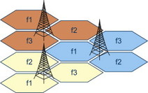
Figure 3.3.1.1 Cells and base stations.
The size and the outline of the cell are controlled by a number of factors including base station and terminal power levels, frequency bands (radio signals using lower frequencies propagate over longer distances than radio signals using higher frequencies if the same power level is used) and antenna configurations. The radio wave propagation environment also has a significant effect on the cell size, there is a large difference depending on if there are lots of buildings, mountains, hills or forests in the area, compared to if the surrounding area is fairly flat and mostly uninhabited.
A fundamental ability of a cellular network is to allow the usage of the same frequency in multiple cells. See Figure 3.3.1.1 where f1 denotes one specific frequency. As can be seen, this frequency can be reused in multiple cells. This means that the total capacity of the network is greatly increased compared to the case if different frequencies would be needed for every site. The most intuitive way of allowing this frequency reuse is to make sure that base stations supporting cells using exactly the same subset of the available frequencies are geographically located sufficiently far apart, in order to avoid radio signals from interfering with each other. However, GSM, WCDMA and LTE have functionality that also allows adjacent cells to use the same frequency sets.
Base stations are located at sites which are carefully selected in order to optimize the overall capacity and coverage of the mobile services. This means that in areas where many users are present, for example in a city centre, the capacity needs are met through locating the base station sites more closely to each other and hence allowing more (but smaller) cells, while in the countryside where not so many users are present, the cells are normally made larger to cover a large area with as few base stations as possible.
Base stations are connected to other network nodes through transmission links, referred to as the RAN backhaul network. GSM and WCDMA radio networks include a centralized node (Base Station Controller (BSC) and Radio Network Controller (RNC) respectively) implementing some of the radio network functionality, while LTE radio networks rely solely on the base stations to provide the complete set of radio functions. While the exact functional division between base stations and BSC/RNC is out of the scope of this book. A brief overview of the most important functions of any digital cellular radio network is described in the following section.
3.3.2 Functionality of radio networks
Although the three radio technologies specified by 3GPP so far (GSM, WCDMA and LTE) are different in several ways, the fundamental functionality of radio networks is common.
The most important functions of a cellular radio network include:
-
Transmission and reception of data over radio carriers. This goes without saying – wireless transmission is naturally a key feature of a radio network. The characteristics of radio transmission are dependant on many parameters such as distance from transmitter, used frequency, if any party is moving, transmission power that is used, height of antenna, and so on. Detailed fundamentals of electromagnetic wave propagation is however out of scope of this book.
-
Modulation and demodulation of the radio carriers. This is a fundamental feature of both analogue and digital wireless transmission. For a digital system, this means that the flow of bits related to a specific service flow (e.g. a video stream) which may arrive at speed of, let us say 2 Mbit/s, are influencing a high-frequency radio carrier through different means. This means that one or more fundamental characteristics of this radio carrier is changed (modulated) at constant time intervals depending on the next set of bit or bits – 0’s or 1’s. This could be, for example, the phase, amplitude or the frequency of the carrier. Every change corresponds to a ‘symbol’ which may consist of one, two or more bits. Today’s most advanced mobile systems (HSPA and LTE) allow for the usage of up to six bit symbols, which means that there are 64 different symbols used. As an example, ‘001010’ may mean a specific phase and a specific amplitude of the carrier, while ‘111011’ may mean the same phase but a different amplitude. See Figure 3.3.2.1 where the two dark points represents these two symbols, the arrow represents the carrier amplitude and the circles represent the phase of the carrier.
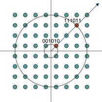
Figure 3.3.2.1 Modulation.
Such more advanced symbol-modulation schemes put high requirements on the quality of the radio channel in order to avoid too frequent misinterpretations by the receiver which is converting the radio carrier changes into a flow of bits on the receiver side, the process naturally known as demodulation.
-
Scheduling of transmission of data from multiple users. This includes buffering of data from different users or applications while waiting for free radio capacity, and may include different priorities between queues of data, allowing different QoS to be applied to different flows of data. There are a number of different scheduling algorithms proposed for optimum sharing of the available transmission capacity based on the needs of services and users.
-
Error correction schemes in order to ensure that the number of bit errors, inevitably occurring over any transmission link, are minimized. There are two main approaches to error correction – FEC (Forward Error Correction) and ARQ (Automatic Repeat reQuest). FEC means that additional data bits (called redundancy bits) are added to the user data through which one or multiple bit errors may be detected and/or corrected. ARQ means that errors detected in a received block of data, for example, through looking at a checksum, are triggering a request to the other party to resend the data. FEC and ARQ are normally combined to increase the performance of the radio channel in that some errors can be corrected through FEC while larger errors need a retransmission through ARQ. How to best balance FEC and ARQ mechanisms in order to maximize the performance is dependant on the requirements of the service and the characteristics of the actual radio channel, and normally also varies over time. Advanced radio communication systems here deploy adaptive coding, whereby the coding protection varies based on knowledge of the radio channel characteristics.
-
Paging of idle terminals. This allows terminals to save battery power through entering what is called ‘idle mode’. This means that the network no longer require the terminals to tell the network every time they move from one cell to another cell. Instead terminals can move within a larger geographical area (defined by the network operator) without contacting the network so frequently and thus saving battery power. This is of course only possible when no services are active. If services are triggered from the network (e.g., through an incoming voice call), the terminal is told to re-attach through the usage of broadcasting paging messages. If services are triggered from the end-user terminal (e.g., the user wants to do a voice call), the terminal is first triggered to leave idle mode including notifying the network of exactly which cell it will be using for the upcoming voice call.
-
Mobility (handover) support to allow for continuous service coverage even if user devices have to change base station or cell due to physical movements in the area. This is of course a very common scenario and very valuable to the end-users. No need to stand still when using a mobile network service.
-
Interference management in order to minimize the disturbance between multiple user devices or cells that share the same or neighbouring frequency bands.
-
Encryption of user data and signalling to protect the integrity and contents of the user transmissions as well as to protect the network from hostile attacks.
-
Power control to efficiently utilize the available power as well as to minimize interference between terminals.
3.3.3 GSM
GSM is the first generation of digital radio technologies specified by ETSI and later on inherited by 3GPP. Since the first generation of cellular networks was based on analogue transmission, GSM is normally referred to as a 2G (second generation) technology. The development of GSM was driven by a wish to specify a standard that could be supported globally, and was supported by many operator and telecom equipment vendors. The work started during the 1980s and the first GSM networks came on air in 1991. Since then, the success and global adoption of GSM has been tremendous. In April 2009, the number of GSM users around the world passed 2.3 billion, making GSM by far the most successful mobile technology to date.
Multiple users are sharing the capacity of one GSM radio carrier which occupy 200 kHz spectrum in any of the supported frequency bands. The most common GSM bands are 900 MHz and 1800 MHz, but also 1900 MHz and 850 MHz are supported and used in some countries.
GSM is a TDMA (Time-Division Multiple Access) technology, meaning that the radio channel is divided into radio ‘frames’. A radio frame is, simply put, an exact number of bits being transmitted on the channel. Each user is then allocated one or more time slots of each radio frame. When GSM is used for telephony, one time slot is needed for every voice call. One GSM radio channel consists of eight time slots per radio frame, meaning that in this case, up to eight users can share one channel simultaneously. It is actually possible to squeeze in up to 16 users into one GSM channel through utilizing what is called half-rate coding, at the expense of fewer bits being available per user and hence potentially a somewhat degraded voice quality (Figure 3.3.3.1).
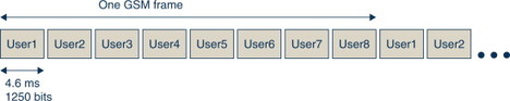
Figure 3.3.3.1 GSM timeframes.
GSM also contains support for packet data services. These services are referred to as GPRS (General Packet Radio Service), and were specified as an add-on to GSM during the mid-1990s. The first GPRS services came on air in the late 1990s. Since the number of bits possible to transmit during one time slot is quite limited due to the small bandwidth of the GSM radio carrier, GPRS allows for one user to temporarily use more than one time slot in order to support higher data speeds. With the addition of EDGE technology (Enhanced Data rates for GSM Evolution) which adds more advanced signal processing technologies to the GSM channel, the peak rates of packet data services over GSM may reach above 400 kbits/s under favourable radio conditions and given that all eight time slots are allocated to one single user.
3.3.4 WCDMA
WCDMA is a third generation (3G) radio technology, and the first version was specified by 3GPP during the late 1990s (it is normally referred to as Rel-99 WCDMA).
WCDMA is specified for 5 MHz wide channels, that is significantly more than GSM. Besides the more advanced signalling processing deployed with WCDMA, this also means that higher data rates can be supported. Rel-99 WCDMA could in theory support user downlink data rates of 2 Mbits/s, but in practice the limit in these networks is 384 kbits/s.
WCDMA is fundamentally different to GSM in that TDMA is not used as a means to separate the traffic from multiple users. Instead the concept of CDMA is deployed, meaning that a specific code is allocated to each terminal. This code is combined with the data to be transmitted, and used to modulate the radio carrier. All terminals are transmitting on the same 5 MHz channel and are separated due to the nature of the code instead of being allocated different frequencies or time slots. In order to allow communication with terminals further away from the base station site, the WCDMA concept includes advanced power control mechanisms which control the power levels of all terminals in the cell 1500 times a second.
Another feature of WCDMA is the ability to support soft handover and macro diversity, mechanisms allowing the terminal to communicate with more than one base station or cell simultaneously, enhancing the performance for the end-user, especially towards the outer parts of the cell.
As a later add-on to WCDMA, 3GPP specified HSPA technologies, allowing a more efficient sharing of the available radio capacity for packet services, and allowing much higher data rates for the end-users.
The WCDMA/HSPA technology is evolved further in 3GPP Rel-8 and beyond, allowing for even higher end-user data rates. Peak data rates exceeding 40 Mbits/s in the downlink direction (from network to mobile terminal) is possible given good radio conditions and moderate system load. This is made possible through introduction of more advanced modulation schemes and ‘MIMO’ techniques (which is further described in the LTE section below). In the uplink direction, HSPA Rel-8 can support up to 11.6 Mbits/s (MIMO (Multiple Input, Multiple Output) is not used). As an additional means of supporting higher data rates, the concept of Multi-Carrier WCDMA can also be used, meaning that more than one 5 MHz WCDMA carrier is used for downlink transmission and that data sent over these carriers is received and combined in the mobile device. This greatly improves the data rates for WCDMA/HSPA.
3.3.5 LTE
Hand-in-hand with the 3GPP System Architecture Evolution work, the work on the next generation RAN was carried out in the LTE study.
Just like the outcome of the SAE work was specifications of EPC, the outcome of the LTE work was specifications of E-UTRAN, short for Evolved UTRAN.
However, names and terms that have been used for some time tend to stick in peoples’ minds. LTE is now the official term for the radio access technology used for E-UTRAN.
The work on LTE started off in late 2004 and early 2005 with defining a set of targets for the upcoming technical study and subsequent specification work. These targets can be found in the 3GPP technical report 25.913, [25.913]. A summary of the most important targets include:
-
Downlink and uplink peak data rates of at least 100 and 50 Mbits/s respectively, assuming that a 20 MHz wide spectrum is used.
-
The time it takes to change a user device from idle to active state shall not be more than 100 ms.
-
The latency (delay) of user data shall not be more than 5 ms in the radio access network.
-
Spectrum efficiency of 2–4× compared to a Rel-6 3G network (spectrum efficiency is measured as the cell throughput in bits/s/MHz).
-
Interruption time during a handover from LTE to GSM or WCDMA of maximum 300 or 500 ms for non-real-time and real-time services respectively.
-
Support for both FDD and TDD multiplexing schemes with the same radio access technology (FDD means transmission and reception on different frequencies while TDD utilizes the same frequency but with transmission and reception separated in the time domain).
-
Support for a wide range of channel bandwidths, ranging from 1.4 MHz to 20 MHz.
Implementations of LTE as defined in 3GPP Rel-8 meets and in many respects even exceeds these requirements. This is made possible through careful selection of technologies including utilization of advanced signalling processing mechanisms. The LTE radio network is connected to the EPC through the S1 interface, a key interface in the EPS architecture (Figure 3.3.5.1).
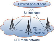
Figure 3.3.5.1 LTE and simplified connection to EPC.
LTE base stations are optionally also interconnected to each other through the X2 interface. This interface is used to optimize performance, for example, for handover between base stations or cells.
The S1 interface is divided into two parts:
-
S1-MME carries signalling messages between the base station and the MME. In addition it also carries signalling messages between the terminal and the MME which are relayed via the base station and piggybacked on radio interface signalling messages over the air interface.
-
S1-U carries user data between the base station and the Serving GW.
The S1 interface will be further described in Chapter 10 (Figure 3.3.5.2).
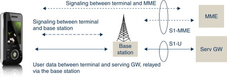
Figure 3.3.5.2 S1-MME and S1-U interfaces.
A key technology for LTE is the OFDM (Orthogonal Frequency Division Multiplexing) transmission scheme which is used for downlink transmission, that is, from the base stations to the end-user devices. This is key to meeting the spectrum flexibility requirements. The basic concept of OFDM is that the total available channel spectrum (e.g., 10 MHz) is sub-divided into a number of 15 kHz channels, each carrying one sub-carrier. The available capacity (the usage of these sub-carriers) can be controlled in both the time and frequency domains at the same time (Figure 3.3.5.3).
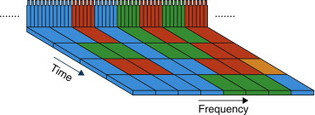
Figure 3.3.5.3 Downlink channel-dependent scheduling in time and frequency domains.
OFDM also has the benefit of being very robust against multipath fading, that is, the variations in signal strength which are typical for mobile communications and are caused by the signal between transmitter and receiver is propagating over multiple paths at the same time. Reflections of the radio waves in various objects mean that multiple copies of the signal arrive at the receiving antenna, since these are not synchronized in time due to slightly different propagation distances (Figure 3.3.5.4).
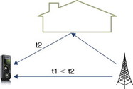
Figure 3.3.5.4 Multipath propagation.
In the uplink direction, that is, from the end-user device to the base station, a slightly different multiplexing scheme is deployed for LTE. As opposed to the LTE downlink, uplink transmission relies on only one single carrier. The key benefit of this is a lower peak-to-average ratio, that is, the amplitude of the power used for transmission is not varying as much as in the case of OFDM. This means a more efficient terminal power-amplifier operation in the end-user terminal, allowing for lower overall power consumption and hence a longer battery life. In order to efficiently multiplex many users with the need to transmit at the same time, LTE allows for allocation of only a subset of the available uplink channel to each user. Still, it is a single carrier per user, as opposed to the downlink transmission scheme.
High peak rates in general rely on radio channels with good characteristics, that is, with low noise and interference, as well as limited load on the cell that is being used. To take advantage of such channels, LTE allows for advanced modulation schemes, collectively referred to as HOM (Higher Order Modulation) schemes. 64QAM is one such scheme, allowing for six bits (26 = 64) to be transmitted for every symbol change on the radio carrier. Another technique is to simultaneously utilize multiple antennas in either the downlink or both the uplink and downlink directions. This technique is called MIMO, and further boosts capacity. With a combination of HOM and MIMO, really high peak rates are made possible with LTE – above 300 Mbits/s in the downlink direction. In the uplink direction, LTE in 3GPP Rel-8 does not include MIMO and the peak rates may reach 75 Mbits/s.
A detailed description of LTE is outside the scope of this book, but an excellent source of information of advanced 3GPP radio technologies including LTE can be found in, [Dahlman 2008].