
Chapter 9 Selection functions
9.1 Architecture Overview for Selection Functions
EPS is an all-IP based system, and thus naturally uses DNS-based mechanism as well as other IETF-defined node discovery mechanisms in order to find appropriate network entities within and among operators’ networks. Even though it is based on IP and Internet-driven technology, EPS has specific requirements stemming from both existing GPRS networks deployed today as well as the specific nature of the networks the operators manage and share resources with and type of services they render. In addition, the nature of the 3GPP Packet Core network Selection Functions is also very much dictated by the fundamental principles of mobility, roaming and security and whether the different network elements should or should not be visible from external networks (e.g. the Internet). In addition, operators also want to be able to manage their existing and evolved packet core through single selection mechanism and include the terminal’s access network capabilities as part of the selection criteria.
The method for how the network entities would be selected for a certain terminal also dictate how the DNS as well as other selection mechanism have been developed for EPS, specially selection of entities such as MME, Serving GW, PCRF and so on. Such core network entities shall not be reachable from external networks or entities which are not governed by the roaming agreements and roaming interconnect networks known as GRX and IPX. Another important factor in the selection of the key network nodes like the Serving GW and PDN GW is the role of certain information elements such as the Access Point Name (APN) identifying the target PDN, the protocol type towards the PDN GW (e.g. PMIP or GTP) and also in certain cases the terminal Identity and the geographic location of some of these entities.
Even though certain adverse network conditions such as overload or even complete failure of a selected MME may also influence the selection of such entities, this is expected to be a rare situation and thus not discussed further.
The main network entities that require special means of selection are: MME, SGSN, Serving GW and PDN GW. In addition, PCRF selection plays an important role when PCC is used.
Figure 9.1.1 shows a topological connection between the nodes that are involved in the selection process of a user’s network attachment procedure in E-UTRAN, these entities remain connected/active for the duration of that specific user’s attachment to the network and removes/disconnects the association only when the user’s session/IP connectivity is removed/closed/disconnected. Additional nodes are involved and participate in the selection process when 2G/3G and non-3GPP accesses are part of the network.
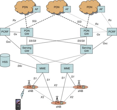
Figure 9.1.1 High-level hierarchical overview of selection entities. Note that for simplicity not all interfaces are shown in the figure.
9.2 Selection of MME, SGSN, Serving GW and PDN GW
9.2.1 Selection procedure at a glance
Let us first illustrate a simplified Initial Attach procedure where an MME, Serving GW and PDN GW need to be selected for the user. The actual message flows for Initial Attach are shown in Chapter 12 but in the flow chart shown in Figure 9.2.1.1, we only show the order of events on a high level.
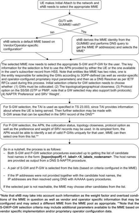
Figure 9.2.1.1 High Level Flows for Selection Function for EPC nodes.
3GPP systems including EPS provide connectivity towards multiple PDNs with independent and unique IP connection for each PDN (see Section 6.2 for more details). Each PDN connection established for a new APN requires an additional PDN GW selection process in the MME. In somewhat simplified terms, the DNS is used to store the mapping between APN and PDN GWs. Since for each user (i.e. UE) there can only be a single Serving GW at any given time in the network, selection of the additional PDN GW must use the current Serving GW information as part of its input data for this selection process. With an APN-FQDN created from the APN as the first query parameter to the DNS procedures, the MME will receive a list of candidate PDN GWs. Based on whether the GW collocation is preferred or not, the MME uses the Serving GW already selected as the next criterion in the selection process. When collocation is desired, the MME selects the PDN GW collocated with the already selected Serving GW, if possible. When collocation is not set, then the protocol used on the S5/S8 (interface (GTP or PMIP) as well as other preference criteria set by the SRV and NAPTR records in the DNS system may provide the next selection criterion. Otherwise MME may select a random PDN GW from the candidates list.
Until now, we have focused on the selection process for the case when a user establishes connectivity in the EPS network. In addition to that, during the mobility procedure such as during handover between 3GPP accesses (for more details, see Section 6.4), an MME or SGSN may need to be changed (e.g. in case of MME pool change) and in such a case, the current serving MME needs to select a new candidate MME to transfer the session to. This selection is performed by the serving node and is based on the Tracking Area Identity (TAI) Fully Qualified Domain Names (FQDN), where the TAI is from the target Cell ID that the target eNB has provided to the serving MME. In case of SGSN selection, either the Routing Area ID of the GERAN or UTRAN is used or, in case of UTRAN, the RNC ID can be used in the same way as the TAI to construct the FQDN to find the right SGSN (pool) with the Rel-8 SGSNs. Note that in case of pre-Rel-8 SGSN, existing selection mechanism must be maintained (see TS29.303, [29.303] for more details) which is simpler and do not necessarily mandate DNS usage.
In the case of Serving GW relocation, which should be a rare procedure and only occur if the Serving GW service area changes, the MME uses the TAI as well as the protocol supported on the S5/S8 reference point (GTPv2 or PMIPv6) in its DNS query to get the appropriate candidate Serving GW list.
Note that the MME is responsible for keeping track of all relevant information for Serving GW as well as each PDN GW per PDN basis, this includes host name, IP address, selected port (if not according to standard) and selected protocol type. The MME needs to be configured with the variant of protocol that is used over the S5/S8 reference point. To support roaming cases, the MME is configured on a per HPLMN basis with the S8 protocol variant (PMIPv6 or GTP).
The HSS may also be provisioned with a specific PDN GW IP address and/or FQDN per APN basis and MME will have this information available during Initial Attach procedure and then this input shall be used to select the P-GW for that user. In particular, to support handovers between 3GPP and non-3GPP accesses where the same PDN GW as was used in source access needs to be allocated in target access, the HSS contains information about the currently used PDN GW. This PDN GW information is provided to the node performing PDN GW selection (e.g. MME for E-UTRAN).
9.2.2 Use of DNS infrastructure
Before going into the details of the individual node selection, it is important to understand the 3GPP structure and requirements on the DNS and its usage. The GPRS system as well as the IP Multimedia Subsystem (IMS) in 3GPP has used DNS extensively, including DNS NAPTR and SRV records developed within the IETF. The EPS continues this and expands DNS usage to include node selection.
The DNS parameters and procedures for EPS are specified in 3GPP TS 23.003, [23.003] and TS 29.303. These specifications, and the DNS related IETF RFCs such as RFC 2181, [RFC 2181], RFC 1035, [RFC 1035], RFC 3958, [RFC 3958] and RFC 2606, [RFC 2606] can be consulted for further details.
Note that the use of DNS infrastructure in order to discover the nodes is not mandatory as operators may choose to use O&M functions and other provisioning methods to achieve the selection process. Use of DNS and its supporting services definitely improves the selection process as various criteria can be used an input to the process and also makes it easy and flexible for inter-operator operations.
In EPS, the DNS is used to store information on mapping between APN, protocol (GTP or PMIP) and PDN GW, as well as mapping between TAI and Serving GW. The DNS can also be configured so that the DNS records provide information on collocated nodes as well as topological/geographical closeness between different nodes. In order to utilize the DNS infrastructure as well as IP-networks, rules are defined for how to construct the FQDN used for DNS procedures. While GGSN selection in GPRS systems use only address (A/AAAA) records in DNS, the EPS DNS procedures support also SRV and NAPTR records and are able to provide the more powerful features already mentioned above, e.g. to support collocated nodes and topological closeness . In particular the Straightforward-NAPTR (S-NAPTR) procedure is used, with a suitable FQDN as input, to retrieve a candidate list of host names and corresponding service (e.g. protocol), port and IPv4/IPv6 addresses. For more detailed information on S-NAPTR, see RFC 3958, [3958] and TS 29.303, [29.303]. Below we briefly describe some of the definitions and rules that are needed for the selection functions.
9.2.2.1 Home network realm/domain
The home Network Realm/Domain need to be in the form of an Internet domain name, for example, operator.com, as specified in IETF RFC 1035, [RFC 1035].
The Home Network Realm/Domain need to be derived from the IMSI as described in the following steps:
-
Take the first 5 or 6 digits of the IMSI, depending on whether a 2 or 3 digit MNC is used and separate them into Mobile Country Code (MCC) and Mobile Network Code (MNC); if the MNC is 2 digits then a zero shall be added at the beginning.
-
Use the MCC and MNC derived in step 1 to create the ‘mnc<MNC>.mcc<MCC>.3gppnetwork.org’ domain name.
-
Add the label ‘epc’ to the beginning of the domain name.
An example of a Home Network Realm/Domain is:
![]()
Where:
-
MCC = 234;
-
MNC = 15;
-
MSIN = 0999999999;
Which gives the Home Network Realm/Domain name: epc.mnc015.mcc234.3gppnetwork.org.
9.2.2.2 DNS sub-domain for operator usage in EPC
The EPC nodes DNS sub-domain (DNS zone) is derived from the MNC and the MCC by adding the label ‘node’ to the beginning of the Home Network Realm/Domain and is constructed as:
node.epc.mnc<MNC>.mcc<MCC>.3gppnetwork.org
This DNS sub-domain is formally placed into the operator’s control. 3GPP never takes this DNS sub-domain back or any zone cut/sub-domain within it for any purpose. As a result the operator can safely provision any DNS records under this sub-domain without worrying about future 3GPP standards encroaching on the DNS names within this zone.
9.2.2.3 Access point name (APN)
Overall structure
The APN is composed of two parts as follows:
-
The APN Network Identifier (APN-NI); this defines the PDN to which the UE requests connectivity and optionally a requested service by the UE. This part of the APN is mandatory.
-
The APN Operator Identifier (APN-OI); this defines in which PLMN the PDN GW (or GGSN for GPRS) is located. This part of the APN is optional.
The APN is constructed by placing the APN Operator Identifier after the APN Network Identifier.
APN network identifier
In order to guarantee uniqueness of APN Network Identifiers within or between PLMNs, an APN Network Identifier containing more than one label shall correspond to an Internet domain name. This name should only be allocated by the PLMN if that PLMN belongs to an organization which has officially reserved this name in the Internet domain. Other types of APN Network Identifiers are not guaranteed to be unique within or between PLMNs.
An APN Network Identifier may be used to access a service associated with a PDN GW. This may be achieved by defining an APN which in addition to being usable to select a PDN GW, is also locally interpreted to be a request for a specific service by the PDN GW. An example would be a unique APN for IMS services.
APN operator identifier
The APN Operator Identifier is a ‘domain name’ of the operator. It contains two labels that uniquely identify the operator (PLMN) as well as a third label that can be common for all operators. For each PLMN there is a default APN-OI that is built up using the MNC and the MCC as well as the label ‘gprs’. The result of the APN Operator Identifier Realm/Domain will be:
mnc<MNC>.mcc<MCC>.gprs
In the roaming case, the UE may utilize the services of the VPLMN. In this case, the APN Operator Identifier need to be constructed the same way, but replacing the Home operator’s MNC and MCC with that of the VPLMN.
APN-FQDN
Note that when the selection function in EPC resolves an APN in DNS, the APN is not used as is. Instead an APN-FQDN is created by inserting the labels ‘apn.epc’ between the APN-NI and the default APN-OI and replacing ‘.gprs’ with ‘3gppnetwork.org’. This results in an APN-FQDN with the following format:
<APN-NI>.apn.epc.mnc<MNC>.mcc<MCC>.3gppnetwork.org
Note that in existing GPRS network, the suffix ‘.gprs’ is used in the DNS instead of ‘3gppnetwork.org’. However, with EPS the suffix ‘3gppnetwork.org’ was chosen for the APN resolutions in DNS. One reason is that the usage of the top level domain ‘.org’ aligns better with the existing top level domains of the DNS infrastructure while ‘.gprs’ does not exist outside of the private 3GPP operator networks. Another reason is that the domain name suffix ‘3gppnetwork.org’ is already used for IMS.
Service and protocol service names for 3GPP
To perform node selection in EPS using DNS, the selection function creates an FQDN (e.g. an APN-FQDN) that is provided in the DNS query to find the host names and IP addresses of target nodes such as PDN GW. Such a target node may, however, be multi-homed (i.e. have more than one IP address) and may use different IP addresses for different protocols (e.g. for PMIP and GTP on S5/S8 interface). In this case, the node selection function needs to resolve the allowed interfaces supporting a certain service (e.g. interface and protocol type) using DNS NAPTR procedure using certain ‘Service Parameters’ describing the service. More detailed description can be found in, Section 6.5 of IETF RFC 3958, [RFC 3958] and in 3GPP TS 29.303, [29.303].
Table 9.2.2.3.1 lists ‘Service Parameters’ to be used in the procedures specified in 3GPP TS 29.303, [29.303].
Table 9.2.2.3.1 List of ‘app-service’ and ‘app-protocol’ names.
| Description | IETF RFC 3958, Section 6.5 ‘app-service’ name | IETF RFC 3958, Section 6.5 ‘app-protocol’ name |
| PGW and interface types supported by the PGW | x-3gpp-pgw | x-s5-gtp, x-s5-pmip, x-s8-gtp, x-s8-pmip, x-s2a-pmip, x-s2a-mipv4, x-s2b-pmip |
| SGW and interface types supported by the SGW | x-3gpp-sgw | x-s5-gtp, x-s5-pmip, x-s8-gtp, x-s8-pmip, x-s11, x-s12, x-s4, x-s1-u, x-s2a-pmip, x-s2b-pmip |
| GGSN | x-3gpp-ggsn | x-gn, x-gp |
| SGSN | x-3gpp-sgsn | x-gn, x-gp, x-s4, x-s3 |
| MME and interface types supported by the MME | x-3gpp-mme | x-s10, x-s11, x-s3, x-s6a, x-s1-mme |
The formats follow the experimental format as specified in IETF RFC 3958, [RFC 3958]. For example, to find the S8 PMIP interfaces on a PGW the Service Parameter of ‘3gpp-pgw:x-s8-pmip’ would be used as input in the procedures defined in IETF RFC 3958.
9.2.3 MME selection
MME selection function is located in the eNB only. The architecture supports multiple eNBs connected to multiple MMEs as well as Serving GWs.
When an UE attempts to attach to E-UTRAN (see Session Management section in Chapter 6 for details), it provides the eNB with parameters; that is, GUTI, (see Section 6.6 on Identities for more details) that would facilitate selection of the appropriate MME based on how the GUTI is constructed. eNB is also informed of the load status of the MMEs within a pool (see Pool information in, Section 6.7) via S1-AP signalling and thus able to provide additional information to the eNBs connected to the MME pool. This allows for efficient selection of MME within a pool and also allows triggers towards the UE (using Tracking Area Update or S1 Release procedures) to reconnect to a different MME within a pool when required. The process of MME selection is designed to be efficient from the UE movement point of view and have been developed to reduce MME change when serving within certain operating boundaries.
The eNB is responsible for the selection of an appropriate MME at UE attachment when no routing to an MME can be determined from the information provided by the UE.
It is important to understand how MME would be represented in the operators’ IP network, in this case how the FQDN for the MME or MME Pool would be constructed, since identifying the correct MME for an UE is dependant on it.
An MME within an operator’s network is identified using an MME Group ID (MMEGI), and an MME Code (MMEC), which is then made available to the eNB via GUTI and/or other parameters that identify the UE in the network (see Identifiers, Section 6.6.).
A sub-domain name is derived from the MNC and MCC by adding the label ‘mme’ to the beginning of the Home Network Realm/Domain.
The MME node FQDN is constructed as:
Mmec<MMEC>.mmegi<MMEGI>.mme.epc.mnc<MNC>.mcc<MCC>.3gppnetwork.org
An MME pool FQDN is constructed as:
mmegi<MMEGI>.mme.epc.mnc<MNC>.mcc<MCC>.3gppnetwork.org
When an MME or SGSN is selecting another MME the TAI FQDN is used towards the DNS to find the appropriate MME (in a pool) and then the information is analysed using A/AAAA queries to get the actual MME address details.
The TAI consists of a TAC, MNC and MCC.
A sub-domain name is derived from the MNC and MCC by adding the label ‘tac’ to the beginning of the Home Network Realm/Domain.
The TAI FQDN is constructed as:
tac-lb<TAC-low-byte>.tac-hb<TAC-high-byte>.tac.epc.mnc<MNC>.mcc<MCC>.3gppnetwork.org
9.2.4 SGSN selection function for EPS
As described in the overview section, the SGSN selection in case of EPS is relevant for Inter-Radio-Access-Technology Handover (Inter-RAT HO) within 3GPP access. In such case, the serving node is responsible to select the target SGSN using either RAI or RNC-ID (in case of UTRAN access only).
A specific SGSN within an operator’s network is identified using the RAI FQDN and the Network Resource Identifier (NRI) which uniquely identifies the core network assigned to the terminal. This identifier can be used by a target MME or SGSN node to connect to the source SGSN node.
The SGSN FQDN is constructed as:
nri-sgsn<NRI>.rac<RAC>.lac<LAC>.rac.epc.mnc<MNC>.mcc<MCC>.3gppnetwork.org
Routing area identity (RAI) – EPC
The RAI consists of a RAC, LAC, MNC and MCC.
A sub-domain name for use by core network nodes based on RAI need to be derived from the MNC and MCC by adding the label ‘rac’ to the beginning of the Home Network Realm/Domain.
The RAI FQDN is constructed in the similar manner as the TAI and would be represented as:
rac<RAC>.lac<LAC>.rac.epc.mnc<MNC>.mcc<MCC>.3gppnetwork.org
9.2.5 GW selection overview
GW Selection includes the Serving GW as well as PDN GW selection process which is performed by the MME. Compared to GPRS, selection of Serving GWs and PDN GWs have become more complex. It is very tightly coupled to the various protocol choices on certain reference points (e.g. S5/S8) as well as certain network configuration such as Local Breakout, in addition to maintaining existing GPRS GGSN selection function parameters like APN.
A related aspect is GW selection by an SGSN that support both Gn/Gp and S4 interfaces and thus may select between GGSN and PDN GW. In this case it is possible for the SGSN to use the information on whether the UE supports E-UTRAN or not (as indicated in the UE capability information sent by the UE) as input to select either a GGSN or a Serving GW and PDN GW. UEs not supporting E-UTRAN may, for example, be allocated a GGSN while UEs supporting E-UTRAN would need to be handled by a PDN GW in order to allow a potential handover to E-UTRAN.
9.2.6 PDN GW selection function
In case of 3GPP access, the PDN GW selection function is located in the MME and SGSN, whereas for non-3GPP access the PDN GW selection function is located depending on the protocol used in the appropriate reference points (i.e. S2a, S2b and S2c).
-
For PMIPv6, it is the MAG functional entity that performs the selection function (an example of such case is the 3GPP2 HSGW entity which is also known as Access Gateway in a generic manner in 3GPP specifications).
-
For MIPv4 FA mode on S2a, the entity requesting the PDN GW is the entity that plays the role of the FA.
-
For DSMIPv6, the UE needs to be provided with an appropriate PDN GW address (to be used as Home Agent address for DSMIPv6). Different methods are available in EPS. When connecting over an access supporting transfer of Protocol Configurations Options (PCO), the PDN GW address may be returned to the UE in such a PCO field. When connecting towards an ePDG, the PDN GW address may be returned to the UE in the IKEv2 signalling with ePDG. If none of these methods are available, then the UE may use DHCP mechanisms or querying a DNS server based on the PDN information (using APN) may be used to select the PDN GW.
The PDN GW selection function uses subscriber information provided by the HSS and possibly additional criteria. The PDN subscription contexts provided contains information such as the APN(s) the user has subscribed to and (for roaming cases) whether this APN(s) is allowed to be connected to using a PDN GW located in the VPLMN, or if the user has to connect via a PDN GW located in the HPLMN.
In the case of non-3GPP accesses using PMIPv6 or MIPv4, the PDN Gateway selection function interacts with the 3GPP AAA Server or 3GPP AAA Proxy and uses subscriber information provided by the HSS to the 3GPP AAA Server. To support separate PDN GW addresses at a PDN GW for different mobility protocols (PMIP, MIPv4 or GTP), the PDN GW Selection function takes mobility protocol type into account when deriving PDN GW address by using the Domain Name Service function, in a similar way as is done by the MME/SGSN.
In case of 3GPP access, the PDN GW selection function interacts with HSS to retrieve subscriber information and uses information such as whether the Serving GW and PDN GW must be collocated; the topological/geographical closeness (described in TS 29.303, [29.303]) and protocol option on the S5/S8 (GTP or PMIP, note that a GW selected may also support both protocols).
Note that collocation of Serving GW and PDN GW is not part of the 3GPP standards specifications for non-3GPP accesses since the use of Serving GW for non-3GPP access is only relevant to a specific case known as Chained S2a/S2b-S8. This chained scenario is not further described in this book. Interested readers should refer to TS 23.402, [23.402] for more details.
In the case a static PDN GW is configured by the operator to be used for that user, the PDN GW is selected by either having the APN configured to map to a given PDN GW (i.e. the APN resolves to a single PDN GW only), or the PDN GW identity provided by the HSS explicitly shows the use of static PDN GW.
The APN may also be provided by the UE. In this case, this UE-provided APN is used to derive the APN-FQDN as long as the subscription allows for it.
If the user is roaming and the HSS provides a PDN subscription context that allows for allocation of a PDN GW from the visited PLMN for this APN, the PDN GW selection function selects a PDN GW from the visited PLMN. If a visited PDN GW cannot be found or if the subscription does not allow for allocation of a PDN GW from the visited PLMN, then the APN is used to select a PDN GW from the HPLMN.
If the UE is requesting a connection to an existing PDN via the same APN, the selection function must select the same PDN GW as it used previously to establish the PDN connection to this APN.
To support the PDN GW selection using the S-NAPTR procedures, the authoritative DNS server responsible for the ‘apn.epc.mnc<MNC>.mcc<MCC>.3gppnetwork.org’ domain must provision NAPTR records for the given APN and corresponding PDN GWs under the APN-FQDN:
<APN-NI>.apn.epc.mnc<MNC>.mcc<MCC>.3gppnetwork.org
Some example S-NAPTR procedures are included here for illustration purposes. For detailed information on 3GPP usage of various IETF specifications and their adaptation for 3GPP network usage, TS 29.303, [29.303] is an excellent source. For 3GPP access:
When non-roaming, the Initial attach the S-NAPTR procedure to get the list of ‘candidate’ PDNGW shall use ‘Service Parameters’ of:
“x-3gpp-pgw:x-s5-gtp”, “x-3gpp-pgw:x-s5-pmip” depending on the protocol supported.
When roaming, the Serving GW is in the VPLMN and if the APN to be selected is in the HPLMN, then the selection function for the S-NAPTR procedure shall use ‘Service Parameters’ of:
“x-3gpp-pgw:x-s8-gtp”, “x-3gpp-pgw:x-s8-pmip” depending on the protocol supported.
When non-roaming and additional PDN connection is to be established, the Serving GW is already selected (i.e. the UE has an existing PDN connection), and the selection function shall use the S-NAPTR procedure ‘Service Parameters’:
“x-3gpp-pgw:x-s5-gtp”, “x-3gpp-pgw:x-s5-pmip” depending on the protocol supported.
For non-3GPP access:
When PMIP is used for Initial attach and both roaming and non-roaming cases, the selection function shall use the S-NAPTR procedure with ‘Service Parameters’ of:
“x-3gpp-pgw:x-s2a-pmip”, “x-3gpp-pgw:x-s2b-pmip”
The additional information is received from 3GPP AAA server/Proxy regarding the appropriate protocol is used over S8 (i.e. GTP vs. PMIP).
9.2.7 Serving GW selection function
In case of 3GPP access, the Serving GW is a mandatory node, whereas in case of non-3GPP access the Serving GW is used only is special case of chained scenario. This chained scenario is not further described in this book. Please refer to TS 23.402 [23.404] if interested to learn more about this feature.
The Serving GW selection function selects an available Serving GW to serve an UE. The selection is based on network topology, that is, the selected Serving GW serves the UE’s location (derived from the TAI) and in case of overlapping Serving GW service areas, the selection may prefer Serving GWs with service areas that reduce the probability of changing the Serving GW as the UE moves around the network.
Due to the possibility of using either GTP or PMIPv6 over the S5 and S8 interfaces as well as possible multiple PDN connections involving HPLMN and VPLMN (in this case the VPLMN provides the network configuration required for Local Breakout where the PDN GW in the VPLMN needs to be selected) when roaming, Serving GWs may need to support both protocols for a single UE connected to different PDNs. This may, for example, be needed in case a UE has two PDN connections, one with PDN GW in Visited PLMN and one with PDN GW allocated in the Home PLMN. In this case PMIPv6 may be used on S5 between the Serving GW and the PDN GW in the Visited PLMN, but GTP could be used for the other PDN connection with PDN GW in the Home PLMN.
Again we show a few examples of S-NAPTR procedures. The detailed information can be found in TS 29.303. For 3GPP accesses:
When non-roaming and TAU procedure requires S-GW change, the S-GW selection function shall use the S-NAPTR procedure with the TAI FQDN to get the list of ‘candidate’ SGW ‘Service Parameters’ of
“x-3gpp-sgw:x-s5-gtp” and/or “x-3gpp-sgw:x-s5-pmip”
When roaming, the SGW selection is needed due to TAU procedure in the VPLMN, then the selection function for the S-NAPTR procedure shall use the TAI FQDN and ‘Service Parameters’ of
“x-3gpp-sgw:x-s8-gtp” or “x-3gpp-sgw:x-s8-pmip”
and make use of the operator’s preference for the roaming protocol (GTP/PMIP).
When non-roaming and additional PDN connection, the SGW is already selected (i.e. the UE has an existing PDN connection), the selection function shall use the S-NAPTR procedure with the APN-FQDN and ‘Service Parameters’ of
“x-3gpp-pgw:x-s5-gtp”, “x-3gpp-pgw:x-s5-pmip”
For non-3GPP access when the Serving GW acts as a local mobility anchor for non-3GPP access S8-S2a/b chained roaming, Serving GW selection is not specified and thus may be left to the vendor-specific implementation choice of a operator’s networks.
9.2.8 Handover (non-3GPP access) and PDN GW selection
Once the selection of PDN GW has occurred, the PDN Gateway identity is registered in the HSS so that it can be provided to the target access in case of an inter-access handover. The PDN GW identity registered in HSS can be either an IP address or a FQDN. Registering the PDN GW IP address is suitable in case the PDN GW only has a single IP address or can use the same IP address for all the mobility protocols it supports (or if it only supports one mobility protocol). Registering the FQDN is more flexible in the sense that it allows PDN GW to use multiple IP addresses depending on mobility protocol. So if a UE hands over from one access where PMIPv6 is used to another access where GTP is used, the PDN GW selection function could use the FQDN to derive different PDN GW IP addresses depending on mobility protocol.
In case the terminal activated the PDN connection in a non-3GPP access, it is the PDN GW that registers the PDN GW identity and its association with a UE and the APN in the HSS. For 3GPP access types, the MME/SGSN updates the HSS with the selected PDN GW identity. Once registered in the HSS, the HSS (possibly via 3GPP AAA Server or Proxy) can then provide the association of the PDN Gateway identity and the related APN for the UE later on. It can be noted that the PDN GW information is provided to target access only in case mobility is performed using a network based mobility protocols in the target access (PMIP and GTP). For handover to a non-3GPP access using DSMIPv6, it is instead the UE that knows the address of the PDN GW (Home Agent).
When the UE is moving between 3GPP and non-3GPP accesses, PDN Gateway selection information for the subscribed PDNs the UE has not yet connected to is returned to the target access system like during Initial Attach. For the PDNs the UE has already connected to, the PDN GW information is transferred as below:
-
If a UE hands over to a non-3GPP access using PMIPv6 in target access and it already has assigned PDN Gateway(s) due to a previous attach in a 3GPP access, the HSS provides the PDN GW identity for each of the already allocated PDN Gateway(s) with the corresponding PDN information to the 3GPP AAA server. The AAA server forwards the information to the PDN GW selection function in the target access.
-
If a UE hands over to a 3GPP access and it already has an assigned PDN Gateway(s) due to a previous attach in a non-3GPP access, the HSS provides the PDN GW identity for each of the already allocated PDN Gateway(s) with the corresponding PDN information to the MME.
9.3 PCRF Selection
The PCRF and its role in the EPS are described in detail in, Section 8.2. For the purpose of PCRF discovery, what is pertinent is that a PDN GW and associated AF may be served by one or more PCRF nodes in the HPLMN. When roaming and need to support local breakout scenarios, one or more PCRF nodes in the VPLMN may be serving the PDN GW and the associated AF. There may be either one PCRF per PLMN allocated for all PDN connections of a UE, or the different PDN connections may be handled by different PCRFs. Which option to use is up to operator configuration. When DSMIPv6 is used however, the only option is to use one PCRF for all PDN connections of a UE.
The Rx, Gx, Gxa/Gxc and S9 sessions for the same IP-CAN sessions must be handled by the same PCRF. The PCRF must also be able to link the different sessions (Rx session, Gx session, S9 session, etc.) for the same IP-CAN session. This applies also to roaming cases where one VPCRF handles the PCC sessions (Gx, Rx, Gxa/Gxc, etc.) belonging to one PDN connection of the UE. Therefore the selection of PCRF and relating an individual UE’s different PCC sessions over the multiple PCRF interfaces for a UE IP-CAN session are very much related. This means that the information carried over these different interfaces must be able to be correlated for the purpose of providing the overall PCC functions towards individual users.
In order to ensure that the same PCRF is selected for all sessions (Gx, Rx, etc) of an IP-CAN session, a logical functional entity called DRA (Diameter Routing Agent) is used during the selection/discovery of the PCRF. 3GPP defines the DRA to be: The DRA (Diameter Routing Agent) is a functional element that ensures that all Diameter sessions established over the Gx, S9, Gxx and Rx reference points for a certain IP-CAN session reach the same PCRF when multiple and separately addressable PCRFs have been deployed in a Diameter realm. The DRA is not required in a network that deploys a single PCRF per Diameter realm. as per 3GPP TS 29.213, [29.213].
DRA complies with standard Diameter functionality as specified by IETF where the Diameter protocol and its applications are specified. DRA also needs to (both Redirect and Proxy DRA) advertise the specific applications supported by it which includes information like support of Gx, Gxx, Rx, S9 as well as necessary and relevant Authentication and vendor-related information for 3GPP.
When operating in the Redirect mode, the DRA Client shall use the value within the Redirect Host AVP of the redirect response in order to obtain the PCRF identity (see Diameter protocol details in Chapter 11).
When in the Proxy mode, the DRA shall select a PCRF only if one has not been already selected for that UE previously and if the request is an IP-CAN session establishment of gateway control session establishment. After a successful establishment of the PCRF for that UE, this PCRF must be used until all IP-CAN sessions for that UE has been terminated and removed from DRA.
When DRA is deployed in a network for PCRF’s realm, the DRA is to be the first contact point from the clients for the sessions.
In roaming scenario, home routed or local breakout, if the DRA is deployed, the vPCRF is selected by the DRA located in the visited PLMN, and the hPCRF is selected by the DRA located in the home PLMN.
In case of roaming, depending on which PLMN the PCRF being selected and in what network configuration (i.e. Local Breakout or not, Home routed or both), the Serving GW, the non-3GPP Access GW and PDN GW may be the selection function trigger towards DRA. The DRA keeps status of assigned PCRF for a certain UE and IPCAN session. It is assumed that there is a single logical DRA serving a Diameter realm (Figure 9.3.1).
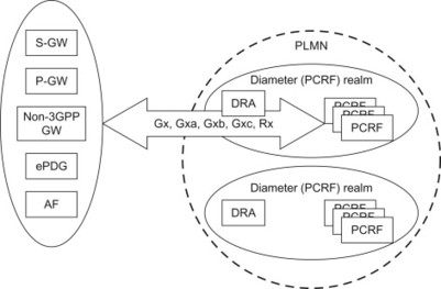
Figure 9.3.1 PCRF selection and discovery using DRA.
The parameters available for the DRA to be able to determine the already allocated PCRF depend on the reference point over which the DRA is contacted. Different information is available on Rx compared to for example, Gx and Gxa/Gxc. Concluding this chapter, we have illustrated in a simplified manner various network node selection criteria as well as methods used in 3GPP.