
Chapter 12 Procedures
This chapter provides a brief introduction to some of the procedures used in EPS. It should be noted that it is not feasible within this book to include a complete description of all procedures that exist in EPS. Instead, we have chosen a few key procedures that should give a good overview for some of the most important use cases. An interested reader can consult the 3GPP technical specifications 23.060, [23.060], 23.401, [23.401] and 23.402, [23.402] for complete descriptions.
12.1 Attach and Detach for E-UTRAN
12.1.1 Attach procedure for E-UTRAN
Attach is the first procedure the UE executes after being switched on. The procedure is performed to make it possible to receive services from the network. An optimization in the SAE system is that the attach procedure also includes the establishment of a default EPS bearer ensuring that always-on IP connectivity for UE/users of the EPS is enabled. An example of the attach procedure is outlined in Figure 12.1.1.1.
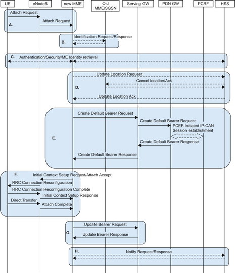
Figure 12.1.1.1 Attach procedure.
The procedure is briefly described in the following steps.
-
The UE sends an Attach Request message to the eNodeB. The eNodeB checks the MME ID transferred in the Radio Resource Control (RRC) layer. If the eNodeB has a link to the identified MME, it forwards the Attach Request to that MME. If not, the eNodeB selects a new MME and forwards the Attach Request.
-
The MME has changed and the MME uses the old MME ID in the GUTI to find the old MME and retrieves the UE context.
-
Authentication and security procedures. The ME identity is also retrieved in conjunction with this step.
-
If the MME has changed, the MME informs the HSS that the UE has moved. The HSS stores the MME address and it instructs the old MME to cancel the UE context.
-
The default bearer is authorized by the PCRF and established between Serving and PDN GW.
-
The default bearer is established over the radio interface and the Attach Accept is sent to the UE.
-
MME informs the Serving GW of the eNodeB Tunnel Endpoint Identifier (TEID) which completes the setup of the default bearer as it can now be used in both uplink and downlink.
-
If the MME has selected a PDN GW that is not the same as the one in the received subscription information, it will send a notification of the new PDN GW identity to the HSS.
In addition there are some additional steps that may be executed together with the attach procedure. For example if the UEs temporary ID (GUTI) is unknown in both the old MME and new MME (after step A and B), the new MME will request the UE to send its permanent subscription identity (IMSI) as shown in Figure 12.1.1.2.
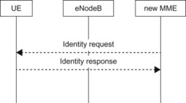
Figure 12.1.1.2 Identity Request.
The MME may check the ME identity with an Equipment Identity Register (after step C). The EIR can be used to blacklist, for example, stolen UEs. Depending on the response from the EIR, the MME may continue the attach procedure or reject the UE (see Figure 12.1.1.3).
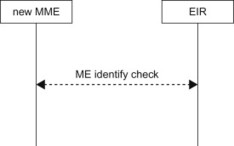
Figure 12.1.1.3 ME identity check.
If the UE would like to send an APN or PCO, it sets a flag in the initial Attach Request message. The MME will then request the information from the UE after the ciphering has started in step C. This way there is no need to send the APN or PCO unencrypted over the radio interface. The ciphered options request procedure is used to transfer the APN and/or PCO to the MME (see Figure 12.1.1.4).
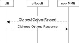
Figure 12.1.1.4 Ciphered options request.
12.1.2 Detach procedure for E-UTRAN
The detach procedure is used to remove bearers and clear states in the network when, for example, the UE is turned off. The detach procedure can also be used by the network to remove the bearers and states for a UE that has missed to perform TA update because it is out of coverage. There may also be subscription or maintenance reasons to detach the UE, for example, if an MME is taken out of service.
Note that in the normal case, the MME address is not removed from the HSS and the MME can retain the UE context. This saves signalling with HSS since it is rather likely that the UE will re-attach in the same MME and then there is no need to inform the HSS and download the subscription data.
12.1.2.1 UE-initiated detach procedure
The procedure is shown in Figure 12.1.2.1.1 and is briefly described in the following steps.
-
The UE sends a Detach Request to the MME because it is turned off.
-
The MME instructs the Serving and PDN GW to delete any bearers for the UE and the PCEF in the PDN GW informs the PCRF that the bearers are being removed.
-
The MME may confirm the detach with a Detach Accept message and remove the signalling connection.
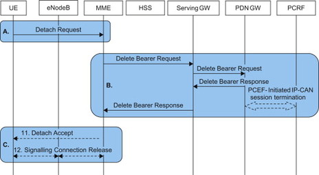
Figure 12.1.2.1.1 UE-initiated detach procedure.
If the UE has not communicated with the network for a long time (longer than the TA update timer) the MME may initiate the detach procedure. In that case, the MME may try to inform the UE with a Detach Request message and then it deletes the bearers as in the UE-initiated detach flow step B (Figure 12.1.2.1.1).
In some special cases, the HSS may also use the detach procedure by sending a Cancel location with cause value subscription withdrawn. This will trigger the MME to remove the UE context, send a Detach Request to the UE and delete the bearers as in step B (Figure 12.1.2.1.1).
12.2 Attach and Detach for Non-3GPP Accesses
12.2.1 General
When the UE is powered on and if a non-3GPP access is available, it may be decided, either automatically by the UE based on policies or by manual choice, to make the initial attach in the non-3GPP access. The UE may, for example, use policies received from the ANDSF. Furthermore, the IPMS mechanisms are used to decide on which mobility protocol is used (see Section 6.4). Finally, it has to be determined whether to treat the non-3GPP access as a trusted or untrusted non-3GPP access.
In this section, we show two examples of attach/detach procedures. First, we describe attach and detach procedures for untrusted non-3GPP access using PMIPv6 on S2b. We then describe the attach and detach procedure for a trusted non-3GPP access when using DSMIPv6 (S2c). Note that the other combinations, that is, trusted access with PMIPv6 and untrusted access with DSMIPv6, are of course also possible but not explicitly showed in the book. For a complete description of the available attach and detach procedures, see TS 23.402, [23.402].
The descriptions are for non-roaming scenarios. It can be noted that in a roaming scenario, the call flows would also include a 3GPP AAA proxy as well as a visited PCRF.
The attach procedure is performed to establish the IP connection and to make it possible to receive services from the network, for example, when the UE is turned on. The detach procedure is used to terminate the IP connections and to clear states in the network when, for example, the UE is turned off.
12.2.2 Attach procedure in untrusted non-3GPP access using PMIPv6 (S2b)
The procedure is shown in Figure 12.2.2.1 and is briefly described in the following steps.
-
The UE establishes a connection to the untrusted non-3GPP access (e.g. WLAN) and receives a local IP address from the access network. There may be access authentication performed (e.g. based on EAP-AKA) but this is optional and not shown in the call flow for simplicity.
-
The UE discovers the IP address of an ePDG using DNS and then initiates the IKEv2 procedure towards the ePDG. EAP-AKA is used for authentication as described in, Section 7.3.5. Diameter is used between ePDG and the AAA server, and between the AAA server and the HSS.
-
When the IKEv2 procedure has progressed, the ePDG sends a PBU to the PDN GW. The PDN GW notifies the PCRF about the new connection. The PDN GW also sends the PDG GW Identity to the HSS (via the AAA server). The PDN GW then responds with a PBA to the ePDG. The PBA contains the IP address for the PDN connection.
-
The final steps of the IKEv2 procedure are executed. The ePDG includes the IP address of the PDN connection in an IKEv2 message to the UE.
-
When the attach procedure is complete, an IPSec tunnel has been established between UE and ePDG and a GRE tunnel between ePDG and PDN GW.
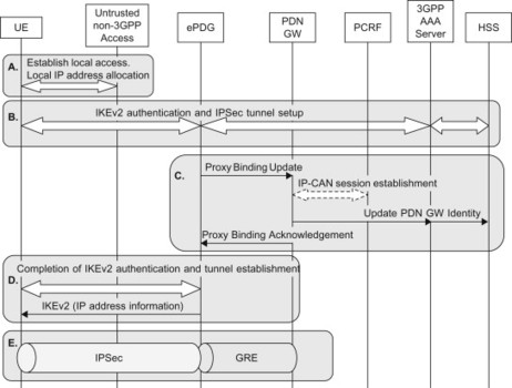
Figure 12.2.2.1 Attach in untrusted non-3GPP access with PMIPv6 (S2b).
12.2.3 Detach procedure in untrusted non-3GPP access using PMIPv6 (S2b)
There is no specific detach procedure in untrusted non-3GPP access. Instead, each PDN connection is terminated separately. In order to detach a UE, all active PDN connections have to be closed. The UE and the network may trigger a PDN disconnection. The HSS may, for example, trigger a termination of all active PDN connections, in case the subscription has been cancelled. For a description of the available procedures, see TS 23.402, [23.402].
The UE-initiated PDN disconnection procedure is shown in Figure 12.2.3.1
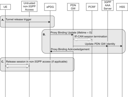
Figure 12.2.3.1 UE-initiated detach in untrusted non-3GPP access with PMIPv6 (S2b).
The procedure is briefly described in the following steps.
-
The IPSec tunnel is released.
-
Since the IPSec tunnel is released, the ePDG sends a PBU to the PDN GW with the lifetime parameter set to zero to indicate that the PDN connection shall be terminated. The PDN GW informs the PCRF that the IP-CAN session is closed. The PDN GW informs the HSS (via the 3GPP AAA Server) to remove the PDN GW identity information that is stored for this PDN connection. The PDN GW also replies with a PBA to the ePDG.
-
The UE may release any resource it has in the non-3GPP access. It may, for example, release the local IP address.
12.2.4 Attach procedure in trusted non-3GPP access using DSMIPv6 (S2c)
The procedure is shown in Figure 12.2.4.1 and is briefly described in the following steps.
-
The UE performs access authentication in the trusted non-3GPP access.
-
The local IP connection in trusted non-3GPP access is stabled and the UE receives a local IP address from the non-3GPP network. The trusted non-3GPP access also initiates a gateway control session establishment with the PCRF.
-
If the UE has not bootstrapped DSMIPv6 security before, it initiates the IKEv2 procedure at this point. Authentication and IPSec SA establishment based on IKEv2 and EAP-AKA is performed. The IPSec SA will be used for protecting the DSMIPv6 signalling.
-
The UE sends a Binding Update to the PDN GW. The PDN GW initiates an IP-CAN session establishment towards the PCRF. The PDN GW replies with a Binding Acknowledgement to the UE.
-
When the attach procedure is complete, there is an IP-in-IP tunnel between UE and the PDN GW. For more details on the operation of DSMIPv6, see Section 11.3.
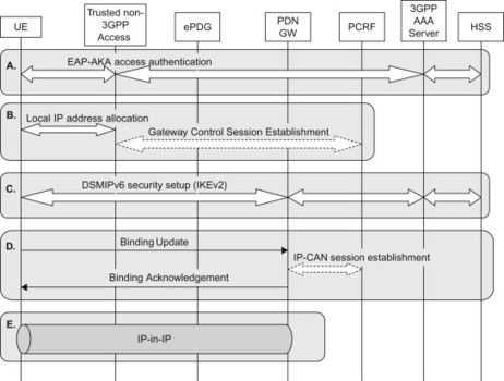
Figure 12.2.4.1 Attach in trusted non-3GPP access with DSMIPv6 (S2c).
12.2.5 Detach procedure in trusted non-3GPP access using DSMIPv6 (S2c)
There is no specific detach procedure when DSMIPv6 is used. Instead, each PDN connection is terminated separately. In order to detach a UE, all active PDN connections have to be closed. The UE and the network may trigger a PDN disconnection. The HSS may, for example, trigger a termination of all PDN connections in case the subscription has been cancelled. For a description of the available procedures, see TS 23.402, [23.402].
The UE-initiated PDN disconnection procedure is shown in Figure 12.2.5.1.
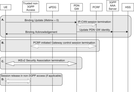
Figure 12.2.5.1 UE-initiated detach in trusted non-3GPP access with DSMIPv6 (S2c).
The procedure is briefly described in the following steps.
-
The UE sends a Binding Update with lifetime zero to indicate that the PDN connection shall be closed. The PDN GW informs the PCRF that the IP-CAN session is closed. The PDN GW informs the HSS (via the 3GPP AAA Server) to remove the PDN GW identity information that is stored for this PDN connection. The PDN GW also replies with a Binding Acknowledgement to the UE.
-
The PCRF sends a message to the BBERF in the trusted non-3GPP access to remove the QoS rules associated with the PDN connection that has been closed.
-
The UE terminates the IKEv2 security association for the given PDN connection.
-
The UE may release any resource it has in the non-3GPP access. It may, for example, release the local IP address.
There are also procedures for allowing the HSS to detach a UE, for example, in case the subscription has been cancelled. For a description of the available procedures, see TS 23.402, [23.402].
12.3 Tracking Area Update
The TA update procedure is one of the mobility management procedures that are used to ensure that the MME knows in which TA, or set of TAs, the UE is currently located in. TA update is performed when the UE moves to a TA outside the list of TAs it was assigned in the previous TA update or attach procedure. TA update is also performed periodically even if the UE remains in the assigned TAs.
12.3.1 Tracking Area update procedure
In its simplest form, the TA update is just a couple of messages between the UE and the MME. The procedure in the simple form is used when the UE has previously performed an attach or a TA update towards the same MME. The trigger for the TA update may be expiry of the periodic timer or that the UE has moved outside the assigned set of TAs.
The procedure is shown in Figure 12.3.1.1 and is briefly described in the following steps.
-
The UE decides to perform a TA update; in this case, the trigger can be either expiry of the periodic update timer or that the UE has moved outside its assigned set of TAs. When the eNodeB receives the TA update request, it routes the message to the correct MME based on the GUMMEI that the UE has placed in the RRC message that transports the TA Update message.
-
The MME recognizes the UE and resets the periodic update timer and sends a TA Update Accept message to the UE. The TA Update Accept message may contain a new list of TAs for the UE. The UE stores the new list of TAs.
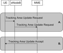
Figure 12.3.1.1 Tracking area update.
12.3.2 TA update with MME change
When moving to LTE from 2G/3G or when the MME is changed, the TA update procedure needs to cater for the change of nodes and update all related nodes accordingly.
The procedure is shown in Figure 12.3.2.1 and is briefly described in the following steps.
-
The UE decides to perform a TA update; in this case, the trigger could be that the UE has moved outside its assigned set of TAs or that the UE moves from 2G/3G into LTE. When the eNodeB receives the TA update request, it detects that the indicated MME is not associated with the eNodeB and hence a new MME needs to be selected. The eNodeB performs an MME selection and forwards the TA update to the selected MME.
-
The new MME uses the GUTI (the MME Identity inside the GUTI) received from the UE to determine where the UE context resides. The MME requests the UE context from the old SGSN or old MME. The request also include the TA Update message, which allows the old MME/old SGSN to validate the integrity of the message. If the message passes the integrity check, the old MME or old SGSN sends the UE context to the new MME. If the integrity check fails, an error message is sent to the new MME which then authenticates the UE. The new MME acknowledges the reception of the UE context message back to the old MME or old SGSN.
-
The new MME informs the Serving GW of the change of MME with an Update Bearer Request. The Serving GW in turn updates the PDN GW with the current RAT type and possibly the location of the UE. PDN GW may also inform the PCRF of the change in RAT type and location.
-
The MME informs the HSS that the UE has moved. The HSS stores the MME address and it instructs the old SGSN/MME to cancel the UE context. The HSS then acknowledges the Location Update.
-
If the old SGSN has an active Iu connection for the UE, the connection is released.
-
The MME completes the TAU procedure with a TA Update Accept message to the UE. The TA Accept message may contain a new list of TAs for the UE and a new GUTI. The UE confirms the new GUTI by sending a TA update complete.
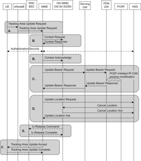
Figure 12.3.2.1 Tracking area update with MME change.
It is also possible to change the Serving GW during a TA update procedure. The MME may decide to change the serving GW, for example, due to non-optimal routing of the user plane after mobility. If this is the case, the MME will inform the old MME/SGSN that the Serving GW is changed in the context transfer procedure. The old MME/SGSN will delete the bearers in the old Serving GW. A change of serving GW is likely a very rare event in most networks, and in networks with collocated Serving and PDN GW, there is no reason at all to relocate the Serving GW (since the PDN GW will anyway remain fixed).
A change of MME due to mobility within LTE will likely be a rare event in most networks, since MME pools can be used to allow several MMEs to share the UEs in a larger area. As long as the UE remain in the pool coverage area, the UE can stay connected to the same MME.
12.3.2.1 Triggers for TA update
TA update occurs when UE experiences any of the following conditions:
-
UE detects it has entered a new TA that is not in the list of TAIs that the UE registered with the network;
-
the periodic TA update timer has expired;
-
UE was in UTRAN PMM_Connected state (e.g. URA_PCH) when it reselects to E-UTRAN;
-
UE was in GPRS READY state when it reselects to E-UTRAN;
-
the UE reselects to E-UTRAN when it has modified the bearer configuration modifications when on GERAN/UTRAN;
-
the radio connection was released with release cause ‘load re-balancing TAU required’;
-
the UE core network capability and/or UE-specific DRX parameters information is changed.
12.4 Handover Procedure
12.4.1 Basic handover
If we consider radio access and packet core network level handover without worrying about the service continuity and session continuity aspects, the following possible handover combinations can be found:
-
Intra and Inter 3GPP access handover
-
Intra E-UTRAN.
-
E-UTRAN to/from UTRAN (GTP or PMIP).
-
E-UTRAN to/from GERAN (GTP or PMIP).
-
Intra GERAN, Intra UTRAN and GERAN to/from GERAN. (These handover cases are not covered in this book.)
-
-
3GPP and non-3GPP handover
-
Optimized handover E-UTRAN to/from HRPD (for GTP and PMIP).
-
Basic non-optimized handover: trusted non-3GPP access (including HRPD) to/from GERAN/UTRAN/E-UTRAN (with GTP/PMIP on 3GPP access and PMIP/MIPv4FA/DSMIPv6 on non-3GPP access).
-
Basic non-optimized handover: untrusted non-3GPP access (including HRPD) to/from GERAN/UTRAN/E-UTRAN (with GTP/PMIP on 3GPP access and PMIP/DSMIPv6 on non-3GPP access).
-
Note that all these scenarios can be Intra or Inter PLMN handover as described below in more detail. In case of handover, we have chosen to focus on trusted non-3GPP access via S2a interface, which implies a network-based mobility using PMIP protocol for non-3GPP accesses and either GTP or PMIP protocol for 3GPP accesses.
12.4.1.1 3GPP radio access
Within 3GPP (as well as in most other cellular technologies) a handover is defined as follows in a very narrow term (as per TS 22.129 [22.129]):
Handover is the process in which the radio access network changes the radio transmitters or radio access mode or radio system used to provide the bearer services, while maintaining a defined bearer service QoS.
Handover is a key mobility mechanism for any cellular systems, whether moving within an access technology or between different access technologies. Core networks play a crucial role in the handover mobility process but in a majority of the cases, the decision to handover is based on the radio conditions.
The UE assists the network by radio measurements about the serving as well as neighbouring cells in the same or different access technologies that may be candidates for handover. The details of how and when the UE and E-UTRAN decides to trigger a handover is far beyond the scope of this book but the interested reader can find more details in, Dahlman (2008).
Handover can be of many different types and forms and if we exclude the process of selecting the target access technology by the UE being handed over to, handover may cause the core network to be involved in the most simplest form of getting the target access network information the UE is connecting to and to a more complex form where one or more core network entities needs to be relocated to better serve the user. In addition to the process of actually changing the radio and/or core network entities, the handover process also needs to ensure the service continuity, that is maintaining the bearer characteristics for active services as far as possible. A system may use handover/cell-reselection mechanism to achieve service continuity for a UE actively involved in a session (transmitting and receiving data). Note that other mechanisms, such as SRVCC, also enable certain specific service continuity for specific type of service(s) which is addressed in a separate section of the book (see Section 12.6).
So what are the different kinds of handovers possible from an overall network perspective? Let us take the example diagram illustrated in Figure 12.4.1.1.1, where it depicts a simple scenario where Operator X and Operator Y have some of their radio networks connected to each other and their core network (here EPC) connected via a GRX/IPX interconnect. Operator X has two EPC networks connected to the RANs OPx1, OPx2, …, OPxn, whereas Operator X has one EPC network connected to RANs OPy1 and OPy2. The first level of handover we can define may be whether the user is moving within Operator X networks thus causing Intra PLMN handover. If the user moves between RANs OPx1 and OPy2, then we have just encountered Inter PLMN handover. During Inter PLMN handover, when the user crosses radio access technology also, such as E-UTRAN to/from UTRAN, the network has also performed Inter System Handover by changing the radio access technology. Note that a UE will only be instructed to measure on neighbour cells to which handover is allowed.
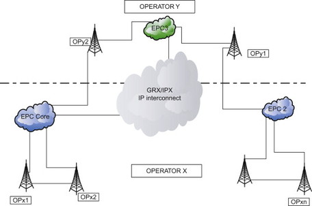
Figure 12.4.1.1.1 Multi-operator simplified 3GPP network diagram.
In case of Inter PLMN handover, a number of aspects need to be understood/established before handover may be accomplished. First of all, in Inter PLMN handover, a session may not only cross an operator’s boundary, but it may also cross country boundary. A call in the United States may, for example, arise in the upstate New York bordering Canada and continue inside Canada if Inter PLMN handover is supported between the two involved operators. As such, Inter PLMN handover is very much up to individual operator’s discretion to support or not. An operator may choose to drop the session and then require the UE to register in the new PLMN instead and in this case, the service continuity is not maintained. Before proceeding with Inter PLMN handover, certain criteria need to be met as specified in 3GPP TS22.129 [22.129]:
-
The ability to check with the home network whether the user is permitted to handover from the visited network to a target network.
-
Invocation of the handover procedure only occurs if the target network provides the radio channel type required for the respective call.
-
The avoidance of ‘network hopping’, that is, successive handover procedures between neighbouring networks for the same call.
-
The possibility of user notification of Inter PLMN HO (e.g. possible tariff change) when it occurs.
During handover procedures, a network may operate in one of the three roles: Home PLMN, Serving PLMN and Visited PLMN. Home PLMN is where the subscriber has his/her subscription. Visited PLMN is the visited network for a roaming user where the user has performed successful registration process (i.e. HSS is aware of where the user is located and has performed all the procedures needed for updating the user’s location). Serving PLMN/network is where the user may have been handed over to (e.g. the cell the user is being served by belongs to the Serving network operator) and has not yet performed the registration process. Most likely scenario is that the Serving PLMN becomes the Visited PLMN after registration unless the user moves out of the serving area/cell.
Shared networks have also support handover of all types, mentioned above, between shared and non-shared networks but some additional aspects, such as the core network it is connected to and the home network where the user has subscription, are also important to take into account.
Even though the most frequent cause of handover is the movement of the user (i.e. the UE), there are other additional triggers that can cause a handover to occur. Some examples of these reasons may be:
-
Triggered due to a service requirement that may be met by a different RAT than the one the UE is being served by and core network may trigger such process.
-
Various radio conditions such as change of radio access mode, capacity of a cell to be able to serve the user’s current services.
Even though, in principle, handover shall not cause any significant loss/change of service or interruption of service, when multiple radio bearers are being handed over from one type of radio access to another, there may be need to drop certain bearers and maintain others based on, for example, priority and relevant QoS information, data rate, delay constraints, error rate, etc. Also, sometimes, certain QoS may be degraded to accommodate the handover of all PS bearers. Overall, instead of failing to handover at all, it would be preferable to be able to handover at least one bearer that is suited for the target radio access. Usually when moving from a higher bit rate to a lower one (e.g. UTRAN to GERAN), then decisions have to be made that suits the serving network operator (HPLMN when not roaming) and an operator may choose to drop all active bearers or based on certain pre-defined criteria choose to handover specific bearers.
So what has changed for EPS compared to what existing handover concepts did not already cover? For example, there is no longer a central entity controlling the RAN like an RNC for UTRAN and a BSC for GERAN. Instead, the eNodeBs in E-UTRAN connects directly to the EPC core network entities, MME for the control plane for signalling and Serving GW for user plane traffic transferring data to/from a terminal for the user. In addition to EUTRAN, the EPS must also support handover to/from non-3GPP accesses such as HRPD network, WiMAX and Interworking WLAN (or I-WLAN as referred to in 3GPP). Thus it is expected that EPS must be able to support handover between heterogeneous access systems, where the non-3GPP access networks are not developed in 3GPP. These handovers also need to support service continuity, thus the ability to maintain IP connectivity within the EPC when moving between these heterogeneous access networks has taken a lot of efforts to accomplish. Even though Inter system handover is usually used in conjunction with 3GPP accesses, this term can easily be expanded to also cover Intra PLMN handover between 3GPP and non-3GPP access. For 3GPP accesses, both Inter PLMN and Intra PLMN handovers as well as Inter System handovers are supported with special emphasis on service continuity between UTRAN and E-UTRAN radio access. In addition, EPS also supports handover from E-UTRAN to pre-Release 8 3GPP networks, but note that the opposite direction is not supported. In this case, the source network (i.e. EPS) has to adopt the target network requirements due to the fact that the target network can not understand/interpret the EPS information due to that pre-Release 8 networks are not upgraded.
Another special aspect of E-UTRAN radio access is that it is a packet-only system and thus there is no support for circuit-switched bearers and CS Domain in the evolved system. So a handover from IMS voice on E-UTRAN EPS to CS voice on 2G/3G has been developed in 3GPP and it is known as Single Radio Voice Call Continuity (SRVCC). It is also possible to provide dual radio-based service continuity between 3GPP and other non-3GPP accesses with IMS, when the non-3GPP access is connected via EPS.
HRPD and 3GPP access
For HRPD, the UE can provide its capabilities regarding other radio accesses and systems it can support and relevant details such as single/dual radio, dual receiver, frequency, etc. via same mechanism as it would do for E-UTRAN access. E-UTRAN is able to configure which other access technology information the UE may be able to provide to the EPS system. Also for handover to/from non-3GPP access, the access technologies must be connected via EPS.
In case of HRPD networks, the requirements on E-UTRAN are very similar to existing 2G/3G 3GPP access networks. The following need to be supported by E-UTRAN and HRPD access network in order to facilitate smoother performance compared to other non-3GPP accesses. As stated previously, the operator requirements are directly linked to the existing networks and subscriber base for CDMA systems. E-UTRAN controls the trigger for UE to measure the HRPD information for preparation of handover, when handover is performed from E-UTRAN to HRPD direction. The HRPD system information block (SIB) has to be sent on the E-UTRAN broadcast channel. The UE monitors the broadcast channel in order to retrieve the HRPD system information for the preparation of cell reselection or handover from the E-UTRAN to HRPD system. HRPD system information may also be provided to the UE by means of dedicated signalling. The HRPD system information contains HRPD neighbouring cell information, CDMA timing information, as well as information controlling the HRPD pre-registration. Note that pre-registration is used only when optimized handover is supported in the EPS, for more details see later sections below.
General non-3GPP and 3GPP access
In case of general non-optimized handover, the UE needs to perform access attach procedure with target access. For handing over to a non-3GPP access, both network-based and host-based IP mobility management solutions are supported (see Section 11.3). For handovers from a non-3GPP access to a 3GPP access, only network-based mobility is supported in target non-3GPP access.
For handover using network-based mobility in target access, the terminal performs access attach with an indication that the attach is of type ‘handover’ in order for the target network (i.e. radio access, MME, Serving GW) to establish the necessary resources for the handover and also where possible, maintain the IP connectivity by maintaining the PDN GW and the terminal’s IP address(es). For host-based mobility in target non-3GPP access, the terminal establishes a local IP connectivity in target access and the handover and IP address preservation is then executed using the host-based IP mobility mechanism. Depending on the number of PDN the UE was connected to before handover, and depending on what the target system can support, the PDN connectivity may be re-established in the target access by the network or by the UE itself or some of them are dropped during handover. So the handover, in this case, has very little interactions with access networks and is performed by the UE and the core network. For more details on these handover procedures, see sections below.
So what we can conclude is that the basic handover requirements remain the same as we move towards E-UTRAN and EPS, but we also continue to enhance the system to accommodate non-3GPP accesses as well as IMS service continuity as we evolve the systems. In the sections below, we will elaborate how the EPS level handovers are supported by the radio and evolved core networks.
12.4.2 Phases and details of handover procedure
12.4.2.1 Overall description
PS handover procedures for GSM were developed with the basic principles of two main phases: Handover preparation phase and handover execution phase. The same principles continue in the handover procedures for EPS as well.
We will briefly go over some of the principles of handover in the existing 2G/3G 3GPP Packet Core (GPRS PS Domain) and then go into the details of the EPS handovers. As in any handover case, there is a source cell in the RAN and a target cell in the RAN (within the same radio access in case of Intra RAT and in a different RAN in case of Inter RAT handover) where the terminal is planned to be moved to. For example, for a 2G system, Intra BSS handover may be performed maintaining the same SGSN (known as Intra SGSN handover) or also changing the SGSN (known as Inter SGSN handover). Or handover may be performed between different radio access type such as between BSS and UTRAN which is known as Inter RAT, where an Inter RAT HO can also be Intra SGSN or Inter SGSN handover. In case of 3G radio access with PS domain GPRS, there can be Inter RNC HO (where the RNC functions including SRNS function is moved) with Intra or Inter SGSN HO, SRNS relocation procedures with Intra or Inter SGSN HO, and Inter System HO with BSS to/from RNC handover is performed with Intra or Inter SGSN HO. In all these handover scenarios, the packet core network is involved and updated during the handover process. Note that the GGSN is not relocated or changed at any handover procedures.
The overall handover process may be described as the source access handling the procedures, such as UE and radio network measurements, to determine handover needs to be initiated, preparing the resources in the target radio and core network side, directing the UE to the new radio resources and releasing the resources in the source radio and core network where applicable, as well as handling gracefully any failure conditions that may occur to get back to a stable status, as well as ensuring that all control and user plane entities are properly connected in the new network. During this process, the uplink and downlink data may be buffered and then forwarded according to the most appropriate path determined by the specific process/handover type itself, thus minimizing any possible loss of user’s data.
Let us analyse the high level view of the two phases (Preparation and Execution) for handover in brief. Figure 12.4.2.1.1 and Figure 12.4.2.1.2 outline the preparation phase and the execution phase for handover respectively.
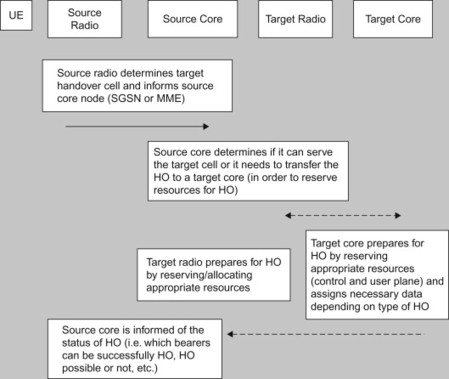
Figure 12.4.2.1.1 Generic overview of the preparation phase of handover.
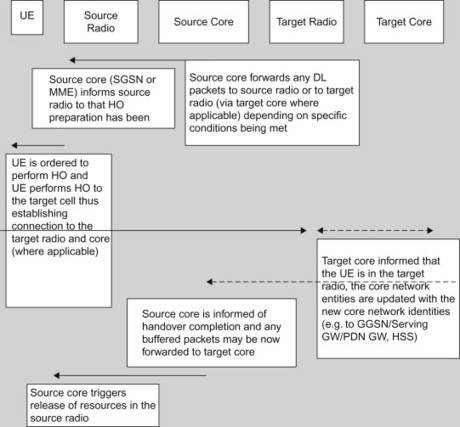
Figure 12.4.2.1.2 Generic overview of the execution phase of handover.
Handover may fail at any time during the handover procedure and handover may also be rejected by the target RAN and source RAN may also cancel the handover due to conditions that could deem that the handover will not succeed or that the process has failed somewhere. In case the handover is rejected or cancelled by the target radio or source radio respectively, all acquired resources would be released and cleared of handover process both in radio and core networks. In case of handover failure, depending on whether the failure occurred during preparation or execution phase, the resources affected and actions needed would be different of course. In case UE fails to connect to the target cell during execution phase, it returns to the source radio and sends appropriate message of failure. If the UE has lost radio contact, then it is source radio’s responsibility to inform source core and then the rest of the path in the target network is cleared/released. If failure is caused due to core network procedures, then appropriate cause code would be sent to the UE and next actions determined (e.g. re-negotiate bearers, etc.).
Handover in EPS for 3GPP accesses
Now let us get started on the main focus of this book, which is to help understand the process of handover involving E-UTRAN and EPS.
In case of EPS and handover involving E-UTRAN, the MME and Serving GW are the involved entities for Intra RAT (LTE) handover. In case of PMIP protocol use, the BBERF located in the Serving GW may also be involved in order to update the PCRF with the right BBERF information. Compared to 2G/3G handover using GPRS, the EPS provides change/relocation during handover for the following possible combinations:
-
Intra E-UTRAN (between eNodeBs) only (Intra MME).
-
Inter E-UTRAN and MME (Inter MME).
-
Inter E-UTRAN and MME and Serving GW (Inter MME and Inter Serving GW).
-
Inter E-UTRAN and Serving GW (Inter Serving GW).
-
Inter RAT (E-UTRAN and GERAN/UTRAN) with core network entities combination of relocation (i.e. MME to/from SGSN relocation and then Serving GW may be relocated).
Inter 3GPP non-3GPP handover is covered in the subsequent sections.
Handover within E-UTRAN access
In certain extraneous conditions such as MME overload, an MME may trigger a relocation of users from the affected to a new MME. Note that compared to 2G/3G, the EPC is clearly separated as control and user plane entities in relation to eNodeB and MME is the control plane entity and Serving GW is the user plane entity. Thus depending on the type of handover performed, multiple entities may be relocated and updated with each other’s information before the handover is completed. As users profile may restrict handover via roaming/area restrictions, MME provides this information to eNodeB via S1 interface and then during handover in active mode of the UE, eNodeB is responsible for verifying whether the handover is allowed or not.
As described in case of 2G/3G, LTE handover is also performed in two main phases, preparation and execution. Though due to the nature of X2-based handover, the execution phase has been further divided into execution and handover completion phase. In the handover completion phase, core network entities like MME and Serving GW then becomes aware of the handover completed and completes the necessary update to the control and user plane paths throughout the bearer connection path. One of the simplest cases is the Intra EUTRAN handover case, described and illustrated in Figure 12.4.2.1.3.
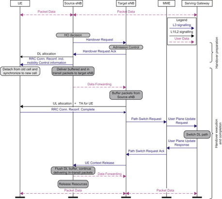
Figure 12.4.2.1.3 Simplified Inter E-UTRAN HO without change of core (Intra MME/Serving GW).
In this procedure, during the preparation phase, the core network entities are not involved. The source eNodeB makes the decision based on UE and radio level information as well as restriction data provided by the core network (i.e. MME) that handover needs to be performed and selects appropriate target eNodeB. eNodeBs are connected with each other via X2 reference point over an IP infrastructure. The source eNodeB is responsible for the decision for which of the EPS bearers are subject to forwarding of packets from the source eNodeB to the target eNodeB, EPC maintains the decision taken, that is no changes are performed. Both source eNodeB and target eNodeB may need to buffer data and during the handover phase, the source eNodeB establishes uplink and downlink data forwarding path for user plane traffic towards target eNodeB.
During the execution phase, the source eNodeB forwards any data received from the downlink path from Serving GW towards target eNodeB as long as the data is arriving and the source eNodeB is able to handle the data. Once the handover has been executed successfully (i.e. the UE is now connected to the target eNodeB), target eNodeB informs MME to switch path and MME then also informs Serving GW to switch the user plane path for the downlink data traffic (i.e. towards the UE) and informs source eNodeB via an end marker about the end of data transfer. This is the simplest type of handover from EPC perspective as can be readily seen.
The procedure is a bit more complex if MME determines that Serving GW relocation may be needed in this case for reasons such as appropriate user plane connectivity, etc. But in order to be able to do a Serving GW relocation, there must be full IP connectivity between source eNodeB and source Serving GW, between source Serving GW and target eNodeB and between target Serving GW and target eNodeB.
At the reception of the Path Switch request from target eNodeB, MME requests target Serving GW to create new bearers as required after the handover completion and target Serving GW updates PDN GW with its address and updated user information, thus completing the new switched path between the UE and the target eNodeB and between the target Serving GW and the PDN GW. When the PDN GW gets the updated information, it starts sending downlink data via this updated path. MME informs Serving GW to release its resources for that UE and target eNodeB releases necessary resources in the source eNodeB, once path switch completion is indicated by MME.
Even though it seems natural to have X2-based handover, it is not reasonable to assume full IP connectivity between all eNodeBs directly from day 1 of E-UTRAN/EPS deployment and there may be other reasons where X2-based handover can not be performed. In such cases, S1-based handover via the core network is the mechanism available for all listed handover cases above.
In case of S1-based handover, either MME or both MME and Serving GW can be relocated even though MME change should not be done unless the target eNodeB belongs to a different MME pool area. If a source MME has selected a target MME for the handover, then it is the target MME’s responsibility to decide if source Serving GW needs to be relocated or not, otherwise it is the source MME’s responsibility to make that decision. The sequence diagram below shows the necessary steps for the handover; note that it is source eNodeB decision whether direct data forwarding will be performed via X2 interface or indirect data forwarding will be performed via source or target Serving GW, depending on whether the Serving GW is relocated or not. Source MME releases source Serving GW resources only when it has confirmation that target Serving GW path switch has been successfully completed.
In case the S1 handover is rejected for any reason, the UE then remains in the Source eNodeB/MME/Serving GW.
Note that we have focused on a GTP-based S5/S8 interface when describing the handover flows, in case PMIP is used, then the interactions between the Serving GW and PDN GW would be slightly different and there is also additional interaction due to the PCC using off path signalling causing additional interactions with PCRF. So when Serving GW change is required, the target Serving GW triggers the GW Session Control procedure to perform policy controlled functions, such as bearer binding, and also informs of RAT change if applicable and then updates the PDN GW. When source Serving GW is instructed to delete the bearers due to Serving GW relocation, it also ensures that PCRF association is removed between the BBERF in source Serving GW and PCRF. In case Serving GW is not relocated, the serving GW then updates PCRF with the updated QoS rules and session binding information which then triggers PDN GW updates for PCC as well. In case of GTP, since the policies are handled on path, these interactions are not needed between Serving GW and PDN GW, though PDN GW may trigger PCC procedures based on, for example, change in RAT type. Note that since the UE, the RANs as well as MME do not differentiate whether GTP or PMIP is used over S5/S8 reference points, there are no impacts on the main handover process due to the core network protocol selection process.
One aspect that is not supported during handover is dynamic protocol change (between GTP and PMIP) over S5/S8 reference points when handover may cause relocation of the Serving GW. The complexity of changing protocol ‘on the fly’ seems unnecessarily complex and the need for such dynamic change in the initial releases of LTE/EPS is not apparent yet. The situation can be made worse when a UE moves from one PLMN to another PLMN during handover and require both MME and Serving GW to be relocated, thus if at the same time a protocol change is also required which affects the PDN GW as well as PCRF.
Handover between E-UTRAN and other 3GPP access (GERAN, UTRAN) with S4-SGSN
When one has to cope with such wide deployment of GSM/UMTS and huge subscriber base (which implies number of terminals in the consumers hands) as well as radio network equipment (GERAN, UTRAN), minimizing impacts on the system when performing handover (and in overall functions) is a key aspect to overall success of EPS. Within 3GPP this type of intersystem handover was also developed during the specification of the 3G system. So the ‘know how’ and commitment were there to achieve the goal of an efficient intersystem handover. But the changes compared to 2G to 3G and 2G/3G to LTE/EPS is much more substantial both from radio and core network perspective, especially in the core network. Since the differences for the handover procedures compared to existing handovers are minimal, we will emphasize on the differences and any additional aspects that would benefit the readers’ understanding of the process.
In case of IRAT handover where E-UTRAN is one radio access technology and EPC is the core network, the same principles apply as before, perform the preparation directed by the source radio network and in case of Inter RAT handover, it is always performed via the core network. The source RAN adapts the content and information flow that suits the target access network (this is crucial in case of handover from E-UTRAN to pre-Release 8 core networks), and as before the source decides to start the preparation of the handover. It is also source RAN that makes the final decision on the execution of the handover procedure.
Inter RAT HO is considered to be backwards handover where the radio resources are prepared in the target 3GPP radio access before the UE is commanded by the source 3GPP radio access to change to the target radio. The target access system is responsible for giving exact guidance for the UE on how to make the radio access there (such as radio resource configuration, target cell system information, etc.) during the preparation phase. Since the RAN connections are not established yet, the signalling and information transfer is done via the core network through the source radio access transparently to the terminal during the preparation phase of the handover.
In Inter RAT HO involving E-UTRAN access, core network entities involved during the preparation and transfer of data are the S4 SGSN and corresponding MME/Serving GW. Whether indirect forwarding is to be applied or not is configured in the MME and S4 SGSN as part of the operator specific data, the configuration indicated whether to perform indirect forwarding always, whether to perform indirect forwarding only for Inter PLMN Inter RAT handover or it is never performed.
The main aspect for this handover is that the MME to/from S4 SGSN relocation must always be performed in case of E-UTRAN to 2G/3G handover.
Handover between E-UTRAN and UTRAN and handover between E-UTRAN and GERAN are very similar; we have chosen to illustrate the procedure by using handover from E-UTRAN to UTRAN as the example. The following steps outline how the generic procedures above apply to handover between E-UTRAN and UTRAN.
-
Once source eNodeB triggers the handover request to the MME, based on the information received, the MME determines that it is UTRAN Iu mode handover. It then selects the appropriate SGSN for the target RNC and initiates appropriate resource reservation process in the target system. MME is also responsible for mapping the EPS bearers that the source eNodeB has selected for handover to the PDP context bearers as applied to 2G/3G. This mapping is specified in 3GPP in order to provide consistent outcome during handover.
-
In the target core network, the SGSN prioritizes the PDP context bearers and decides whether Serving GW needs to be relocated. If Serving GW is to be relocated, then SGSN selects the appropriate target Serving GW and triggers the appropriate resources allocation.
-
SGSN also provides the target RNC with all relevant information provided by the source network in order to establish the radio resources required for handover. Once the target RNC has completed all necessary radio resource allocation towards the UE and user plane resources have been established for the Iu, target SGSN is informed of the completion of the process. At this point, the target RNC is prepared to receive user plane data from either the SGSN or Serving GW, depending on if direct tunnel is applied or not (in case of no direct tunnel, SGSN remains in the user plane path).
-
Source MME and source eNodeB are then informed of successful handover resources reserved and preparation phase is completed.
-
In case of indirect forwarding, the path is established by the SGSN in the target Serving GW and by the source MME in the source network.
-
Once source MME informs source eNodeB about handover preparation completion, source eNodeB starts forwarding data and commands the UE to perform handover to the target RNC and provides the UE all necessary information provided by the target RNC. At this time, UE no longer receives/sends any data via source eNodeB.
-
The UE tunes into the target cell in which the radio bearers are established and the rest of the process continues in the core network where the target SGSN informs source MME of the handover completion when target RNC confirms it to the target SGSN. After that, the source MME and target SGSN needs to release any forwarding resources. The source MME also needs to release source Serving GW resources in case of Serving GW relocation and Serving GW updates the PDN GW with appropriate information to establish the user plane path between the RNC, SGSN, Serving GW and PDN GW.
Note that any EPS bearers that were not successfully transferred are deactivated by the SGSN and Serving GW and any downlink data are dropped in Serving GW. Also note that UE only re-establishes the bearers that were accepted by the target network for handover during preparation phase. Further information flows and much more detailed description of the handover procedure between E-UTRAN and GERAN/UTRAN are available in 3GPP TS 23.401, [23.401].
Handover for Gn/Gp-based SGSN
Interoperation scenarios for operating E-UTRAN with a PLMN maintaining Gn/Gp SGSNs are supported for GTP-based S5/S8 interfaces. Thus, the PDN GW then acts as a GGSN supporting Gn/Gp interfaces towards the SGSN, the MME supports Gn interface towards SGSN. Note that HSS must also be able to work with Gr interface or supported via interworking function to enable interworking between S6a and Gr functions.
The main principles for handover between E-UTRAN and UTRAN/GERAN connected to Gn/Gp core networks are as follows:
-
The handover procedures within E-UTRAN involving MME and Serving GW remain as in the case of using EPC core for GERAN/UTRAN.
-
The handover procedures within GERAN/UTRAN involving existing GPRS procedures remain the same as currently specified without EPC.
-
A handover from E-UTRAN to UTRAN/GERAN would imply executing Inter SGSN handover with the source SGSN represented by the MME for EUTRAN.
-
A handover from UTRAN/GERAN to E-UTRAN would imply executing Inter SGSN handover with the source SGSN represented by the Gn/Gp SGSN for UTRAN/GERAN and target SGSN represented by MME for EUTRAN. In addition, the MME has to select the Serving GW and the Serving GW must also update the PDN GW with the appropriate S5/S8 related information.
-
Serving GW establishes appropriate set up towards eNodeB.
-
If indirect forwarding is to be performed, then MME performs the same procedure as for Inter EUTRAN handover described above.
-
The PDN GW represents the GGSN function and the GGSN selected for the UTRAN/GERAN must be a PDN GW acting as a GGSN.
-
Mapping between PDP context and EPS bearers as well as other parameters also handled in the appropriate entities (such as MME takes care of handling the security and QoS parameters).
Note that in order to allow for early implementation of UE and early deployment of networks there is an additional possibility to support mobility between E-UTRAN and UTRAN/GERAN. This mobility solution is based on RRC connection release with redirection information. The RRC connection release with redirection information is implemented in the Source eNodeB and does not require any additional support in the network. The redirection information points the UE towards GERAN or UTRAN where the UE will use existing routing area update procedure to recover the connection. This procedure has worse performance than the other handover solutions and may create a significant break in the connection. It may however have acceptable performance for early deployments with primarily less data only users.
Handover between GERAN and UTRAN access using S4 SGSN and GTP/PMIP protocol
For GERAN and UTRAN access, handovers have been developed and deployed for a long time, now using GPRS and GTP as its core protocol. During the SAE development process, there were no significant interest from any operators to develop PMIP or even for GTP-based 2G and 3G to access handover support when S4 SGSN is in use. But during the course of the standardization work, the interest in completing an EPC-only architecture for all 3GPP accesses including the ability to handover between 2G and 3G radio networks using EPC grew. The work did not require too much extra efforts from technical point of view, since it can be easily extended from the EPC support for 2G/3G. Specifications were developed such that S4 SGSN and Serving GW and PDN GW-based EPC architecture supports handover between GERAN and UTRAN as well as Intra GERAN and Intra UTRAN mobility with and without SGSN relocation and Serving GW relocation. The extra signalling required is to interact with Serving GW in the appropriate time of the handover for bearer establishment; as well as in case of PMIP, the additional PCRF interactions are also required. 3GPP TS23.060 has described the procedural differences in a nut shell that includes appropriate message name used between the SGSNs following EPC messages; the EPS bearer is used as parameter and Serving GW and PDN GW are updated with appropriate bearer information as in the E-UTRAN to/from 2G/3G case.
12.4.3 Handover in EPS with non-3GPP accesses
12.4.3.1 Optimized handover for eHRPD access
For HRPD networks, there is a significant subscriber base already out there with major North American and Asian operators operating their networks. Even though the two technologies (one developed in 3GPP and the other in 3GPP2) have been competing over the last 20 years, the two bodies have also cooperated in many areas in order to develop common standards that are strategically important to operators overall, examples of these are IMS and PCC development. For CDMA a number of companies cooperated extensively inside and outside the standards forum in order to develop special optimized handover procedures between E-UTRAN and HRPD access. The resulting handover procedure has efficient performance and reduced service interruption. This work was brought into mainstream 3GPP standards under the SAE umbrella and further enhanced and aligned with the mainstream 3GPP work ongoing for SAE and thus produced the so-called Optimized Handover between E-UTRAN and HRPD. HRPD networks then became known as evolved HRPD (eHRPD) to highlight the changes required for interoperability and connectivity with EPC and E-UTRAN, though there are no changes to the actual radio network and its functions.
The optimized handover has been defined to work in two modes of operation: idle mode where the UE is idle (i.e. do not have any active radio connectivity in the system, ECM-IDLE in E-UTRAN and Dormant in HRPD) and active mode where the UE is active (i.e. active data transmission ongoing between the UE and the network). The actual handover is performed in two phases: pre-registration phase where the target access and specific core network entity for the specific access (MME for E-UTRAN and HRPD Serving GW or HSGW for eHRPD access) is prepared ahead of time anticipating a possible handover (but there is no time association of how long a UE may be pre-registered in the system); and handover preparation and execution phase where the actual access network change occurs.
Note that in the early deployment of E-UTRAN in a CDMA network, it is considered more prevalent and thus important to support E-UTRAN to HRPD handover than the reverse direction, since it is assumed that the HRPD networks would have sufficient coverage to keep a user within HRPD system.
It should be noted that currently the HSGW only supports PMIP protocol (S2a interface) whereas the E-UTRAN access may be using either GTP or PMIP protocol and as such, the GRE keys must be provided to the HSGW even in case of GTP-based EPC for E-UTRAN access.
Figure 12.4.3.1.1 outlines the steps for the EUTRAN to HRPD access handover.
-
Some of the basic requirements on the UE and the E-UTRAN when supporting handover from E-UTRAN to HRPD networks are that the E-UTRAN provides the HRPD information (e.g. neighbouring cell information, CDMA timing and HRPD pre-registration control information) on the broadcast channel for UE measurement purposes. HRPD system information may also be provided to the UE by means of dedicated signalling. E-UTRAN is responsible for configuration and activation of HRPD measurements towards the UEs. The UE performs measurements in active mode when directed by the E-UTRAN network using information provided via the dedicated radio signalling. Note that for idle mode, the UE performs cell reselection procedures in addition to being pre-registered in the target system prior to perform idle mode optimized mobility.
-
Once the UE decides to perform pre-registration to HRPD, it needs to tunnel the HRPD messages over E-UTRAN radio. The HRPD messages are encapsulated in the appropriate uplink messages for pre-registration or for handover signalling and downlink messages for other HRPD messages. The handover signalling is given higher priority and the RAT type and other identifying information is also provided towards HRPD network for interpretation of the messages correctly. In order for the MME to select the correct target HRPD system, where the messages for that UE should be tunnelled to and also assist the HRPD network with the collected appropriate radio-related information, each eNodeB cell is associated with a HRPD Sector ID (also known as reference cell ID). This Sector ID is provided to the MME during the message transfer over S1-MME. MME then uses this information to find the appropriate target HRPD entity and tunnels the messages over S101 towards that entity.
-
Based on the trigger from E-UTRAN radio network, the UE initiates establishment of new session in eHRPD network. This process causes the HSGW to be connected with the HRPD access network and based on the information provided by the UE via the EPC, the HSGW also initiates the process of establishing connection with PCRF for non-primary BBERF connection in order to provide functions like bearer binding, QoS rules provisioning as the BBERF function is located in the HSGW for this access. At this point, HSGW has the latest bearer information, APN, PDN GW addresses, etc. for that user. HSGW acquires the information about the already allocated PDN GWs from HSS/AAA. When the source E-UTRAN makes the decision to trigger the UT to handover to target HRPD access, the UE starts sending the appropriate preparation messages to the HRPD access network via the tunnels over E-UTRAN and MME.
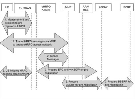
Figure 12.4.3.1.1 Preparation and pre-registration overview.
Figure 12.4.3.1.2 outlines the steps for the EUTRAN to HRPD access handover completion phase:
-
Based on the measurement information, source E-UTRAN instructs the UE to perform handover to the HRPD access network, UE has already pre-registered to the HRPD network prior to any active mode optimized handover.
-
The UE initiates the procedures to establish traffic channel connection towards the HRPD access network over the E-UTRAN access, E-UTRAN forwards the message to the MME which then forwards the message to HRPD node via the already established S101 tunnel and also adds additional information such as uplink GRE keys, APNs and PDN GW addresses associated with each APN.
-
HRPD access network then establishes the necessary radio resources and requests HSGW for appropriate links and information in order to establish the connection between HRPD and HSGW. Once this process is completed, the MME is notified and then the MME may establish an indirect forwarding link between Serving GW and HSGW by sending the Serving GW the necessary HSGW information. In this manner, there is a data forwarding path from eNodeB to Serving GW to HSGW.
-
UE is informed of successful resource allocation completion and the UE tunes to the HRPD access network. The UE no longer communicates via E-UTRAN access.
-
UE then sends a confirmation message directly to the HRPD network, at this time the UE has completely moved into HRPD access network. HRPD access network informs HSGW of UE’s arrival and being prepared to receive/send data.
-
HSGW now establishes link with PDN GW where the PDN GW shall now forward data towards HSGW and not Serving GW.
-
PDN GW now interacts with PCRF function to receive any modified data for the new access.
-
The S10 tunnel is terminated for that UE between HRPD and MME access.
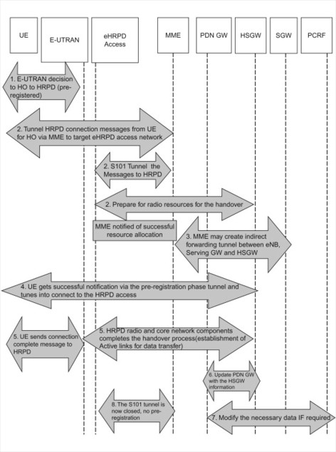
Figure 12.4.3.1.2 Active mode handover from E-UTRAN to HRPD in the EPC.
In case of multiple PDN connections existing for that UE, the HSGW must update the appropriate PDN GWs for each PDN connection individually.
The release of E-UTRAN resources is consistent with E-UTRAN Inter RAT handover scenario; note that the PDN GW can initiate resource release towards Serving GW anytime after it had successfully established the link with HSGW. Once MME receives confirmation from HRPD network about successful completion of handover, it initiates the release of UE context towards E-UTRAN.
MME may have timers to trigger the Serving GW resources for the E-UTRAN bearers and the indirect forwarding tunnels to be released as in Inter RAT handover case. When MME does trigger this release, it also indicates to Serving GW not to release resources towards the PDN GW.
In case of handover from HRPD to E-UTRAN access, the E-UTRAN access does not play any role in directing or assisting the UE. Due to possible impacts of HRPD radio access part, it is unclear during the writing of this book, if the HRPD RAN would assist in any way for this handover or it will be up to the UE to decide when to perform the handover based on measurements available to it. The steps are very similar to the E-UTRAN to HRPD handover with some differences due to the access network type (Figure 12.4.3.1.3).
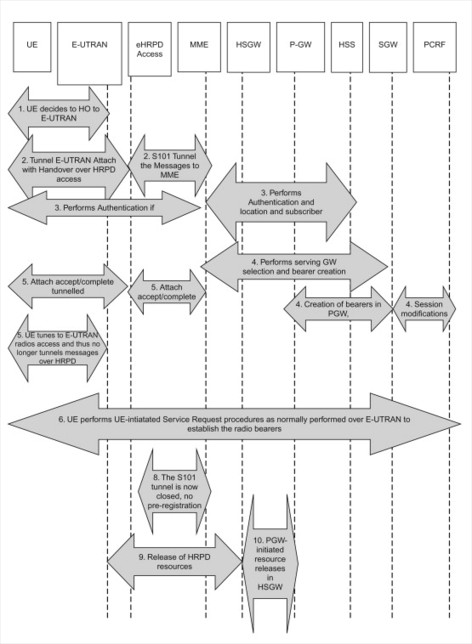
Figure 12.4.3.1.3 HRPD to E-UTRAN active mode handover.
The procedure is briefly described in the following steps.
-
The decision to handover to E-UTRAN is made by the UE. The UE is in active mode in HRPD network connected via EPC. Note that the UE may choose to leave HRPD and execute E-UTRAN attach procedure directly over E-UTRAN, in such case the Attach type is not set to Handover.
-
UE sends a NAS message of Attach to E-UTRAN with indication set to Handover which is tunnelled over HRPD access network and then forwarded to MME via the pre-established S101 tunnel. The HRPD access node determines the MME and the TAI using the Sector ID to MME mapping function located in HRPD network.
-
Based on E-UTRAN attach process, MME needs to make the appropriate decision of whether to perform authentication or not. MME also performs location update procedure in order to update the HSS with user information as well as retrieve the user’s subscription data.
-
As in normal E-UTRAN attach procedure, the Serving GW is selected for that UE and bearer creation process for default bearer is initiated with an indication of handover. Serving GW triggers PDN GW to create the necessary information for the default bearer establishment. PDN GW performs this task and also triggers associated, dedicated bearer establishment procedures.
-
Once MME is informed of the bearer establishment procedure completion in the GWs, MME completes the attach procedure towards the UE via the HRPD access network and associated established tunnels. UE then completes the attach procedure over the HRPD access.
-
Once the attach procedure is completed, the UE moves to E-UTRAN access.
-
UE then performs necessary radio connection establishment via the service request procedure which triggers the establishment of radio links as well as the S1-user plane set up and then start the UE-initiated bearer establishment procedures to complete the process. For any bearers that could not be established during this process, the UE removes the resources for them.
-
Once the bearer establishment procedure is complete, the MME informs HRPD access via S101 tunnel that handover is complete.
-
HRPD access network initiates its resources release procedure.
-
PDN GW triggers the resources to be released towards HSGW anytime once it has established the Serving GW and PCRF relationship for the E-UTRAN access.
If there are multiple PDN connections to be established, the UE must initiate them via UE-initiated PDN connectivity process as described in, Section 6.3.
What is evident is that by pre-establishing some of the connections within the target access network anytime prior to the actual handover itself, the execution of the actual handover process is reduced significantly during E-UTRAN to HRPD scenario. Even though the benefits may not be as significant for the reverse direction, for the consistency and simplicity of the network behaviour, the process has been kept consistent.
Even though this section focuses on active mode handover, it may benefit the readers to be exposed to the idle mode handover process between E-UTRAN and HRPD.
In case of E-UTRAN to HRPD direction, triggered by cell reselection process, the idle UE based on triggers internal or from E-UTRAN access, selects the HRPD access network where the UE is in dormant state due to either pre-registration or previous attachment to that access. Then the UE follows the HRPD procedures to connect to the access and in the core network, the HSGW establishes appropriate bearers towards the PDN GW and PCRF when applicable. PDN GW then triggers the release of the resources in the E-UTRAN access.
In case of HRPD to E-UTRAN direction, when the UE determines to perform an attach procedure to E-UTRAN access, the process it follows is the same as the active mode handover process until it tunes to the E-UTRAN access. Then the UE performs a TA update procedure over the E-UTRAN access. The resource release process is the same as in the reverse direction, triggered by PDN GW.
Basic non-optimized handover with non-3GPP access
When considering non-optimized handover between and within non-3GPP accesses using EPC, the main requirement is to be able to preserve the IP address(es) and maintain the IP connectivity/service continuity when handover is occurring. Since the handover decision is determined and executed from the UE, and there is no coordination between the access networks, this procedure is considered non-optimized compared to the optimized handover procedure between E-UTRAN and HRPD access.
Due to the number of protocol options as well as capability to support both host-based and network-based mobility, the handover procedure can get quite complex in terms of selecting the right combination to ensure that IP address preservation and session continuity is possible. As the reader may be by now already familiar with the IP mobility management selection process as described already in previous sections of this book, this plays a significant role in the handover process as well.
In case of handover between 3GPP access and non-3GPP access and between non-3GPP accesses, IPMS function performs the decision of how the IP connectivity shall be performed (i.e. preservation possible or not). In case of network-based mobility (i.e. PMIP), the PMIP protocol supports these functions and the UE capability is either indicated by the UE explicitly at handover or based on pre-configured information.
In case of host-based mobility, the decision is slightly differently taken. The decision may take place if the network is aware of the UE capability to support DSMIPv6 or MIPv4. This information may be acquired by the target non-3GPP access from the HSS/AAA (e.g. in case of DSMIPv6, the UE performed S2c bootstrap before moving to the target non-3GPP access). If the IP mobility management protocol selected is DSMIPv6, the non-3GPP access network provides the UE with a new IP address, local to the access network. In an untrusted non-3GPP access, the terminal also has to set up an IPSec tunnel with the ePDG. In these cases, in order to get IP address preservation for session continuity, the UE has to use DSMIPv6 over S2c reference point. The local IP address, allocated either by the trusted non-3GPP access network or the ePDG, is then used as a Care-of Address for DSMIPv6 within EPS. If the IP mobility management protocol selected is MIPv4, the address provided to the UE by the trusted non-3GPP access network is a FACoA and IP address preservation is performed over S2a using MIPv4 FACoA procedures. Note that MIPv4 is not supported when an ePDG is used. A basic handover flow when using DSMIPv6 is provided below. If the reader is interested in further details on the handover flows using host-based mobility protocols, then we recommend further detailed reading of 3GPP specifications, TS23.402 and TS24.303. Further details on the basic operation of DSMIPv6 are also described in, Section 11.3.
As can be understood from IP Mobility Selection function, the protocol choice made by the UE and the protocol choice supported by the network requires to be in sync in order to perform handover, the UE indicates at the attach procedure that the attach function is being performed due to handover and it may also indicate its preference of host- or network-based mobility and the protocol choice for host-based mobility case. Note that in case of network-based mobility in 3GPP, the UE is unaffected by the network choice of protocol (GTP or PMIP). If UE does not indicate any preference, then PMIPv6 is the selected protocol and based on the PMIP protocol principles, there are two ways of making the decision of preserving the IP and maintain session continuity or not. An operator may configure its local policies at PDN GW whether to preserve the IP address based on a timer which allows the existing IP address to be maintained IF and only if the source/old access system tears down its connection before the timer expires and then assigns a new IP prefix, or assigns a new IP prefix immediately and thus no IP address preservation is performed.
In addition, the UE may also use information made available to it from ANDSF regarding its home operator’s preference and other policies to assist it to select the preferred access network during handover.
Now let us focus on the scenario that has generated wider participation and opened operators’ interest during the development and standardization of SAE (i.e. S2a interface using PMIPv6). This is also the default system behaviour if the operators choose not to configure any specific IPMS process in the UE and in the EPC network. Note that multiple PDN connectivity with different mobility protocols for the same UE is not supported, that means, for example, it is not possible for a UE that is connected to single or multiple PDNs over a 3GPP access to perform a handover to a non-3GPP access and then use different mobility protocols for the PDNs connected over non-3GPP access. We consider the flow in Figure 12.4.3.1.3 to cover the most likely scenario to be seen in the deployed network, where a handover is triggered from a trusted non-3GPP access network with S2a supporting PMIP to GTP-based (S5/S8 interface) EPC network (Figure 12.4.3.1.4).
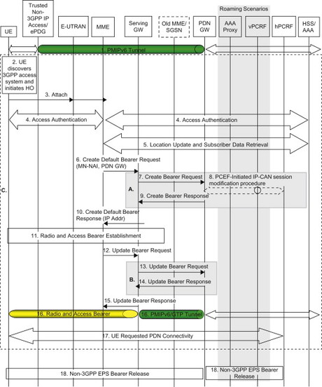
Figure 12.4.3.1.4 Handover from a trusted non-3GPP access network.
The handover steps can be described as follows:
-
Steps 1–3: The UE is connected to a non-3GPP access trusted by the operator and in active mode, the UE detects the E-UTRAN access and determines to handover (or rather transfer the sessions, as it is more a transfer of ongoing active sessions than ‘handover’ in the true meaning of this word as used in the existing mobile systems) to E-UTRAN from its current serving access system based on policies and other information available to the UE. Note that the UE is connected to an EPS network and has now moved to E-UTRAN access to perform an attach. The UE sends an Attach Request to the MME over the E-UTRAN access with attach type indicating ‘Handover attach’. This attach procedure is handled as in case of normal attach in E-UTRAN and the UE should also include one of its APNs in this message.
-
Steps 4–6: The MME may perform authentication of the UE as per E-UTRAN access via HSS. Once the authentication is successful, the MME continues as for an E-UTRAN access where it may perform location update procedure and subscriber data retrieval from the HSS. The MME receives information on the PDNs the UE is connected to over the non-3GPP access in the subscriber data obtained from the HSS. The MME selects an APN, either the default APN or the APN provided by the UE. Since the attach type sent by UE is ‘Handover’, the MME selects the PDN GW provided as part of the subscription data from the HSS. The MME then continues to select a Serving GW. The MME sends a Create Default Bearer Request to the selected Serving GW and includes the PDN GW address and handover indication.
-
Steps 7–10: The Serving GW sends a Create Default Bearer Request with handover indication to PDN GW causing the PDN GW not to switch the tunnel from non-3GPP IP access to 3GPP access system at this point. PDN GW also interacts with PCRF to obtain the rules for the network IP-CAN and PDN connection for all established bearers due to handover. Due to the handover, the PDN GW stores the new PCC rules for E-UTRAN access as well as maintains the old PCC rules for the trusted or untrusted non-3GPP IP access and still applies the old PCC rules for charging. PDN GW returns the UE’s IP address/prefix assigned for the non-3GPP access it is handing over from. This information is then passed onto MME indicating successful bearer establishment and set up of S5 tunnel establishment. Additional dedicated bearers may also be established during this process by PDN GW as in case of normal attach.
-
Step 11: Radio and access bearers are established for E-UTRAN access as in the normal attach case.
-
Steps 12–15: The MME sends an Update Bearer Request (eNodeB address, eNodeB TEID, handover indication) message to the Serving GW. Based on the presence of the handover indication, the Serving GW sends an Update Bearer Request message to the PDN GW to prompt the PDN GW to tunnel packets from non-3GPP IP access to 3GPP access system and immediately start routing packets to the Serving GW for the default and any dedicated EPS bearers established. PDN GW can now route the packets to E-UTRAN access and stop data transfer to non-3GPP access.
-
Step 16: The UE sends and receives data at this point via the E-UTRAN system.
-
Step 17: For connectivity to any remaining PDNs from the old non-3GPP access, the UE establishes connectivity to each PDN, by executing the UE requested PDN connectivity procedure.
-
Step 18: The PDN GW initiates resource allocation deactivation procedure in the non-3GPP IP access.
In case the E-UTRAN access is using PMIP-based EPC, the difference in signalling sequences is illustrated by the steps (A) and (B) where dynamic PCC interaction based on off-path policy control related signalling are executed as seen in general where the Serving GW interacts with PCRF. In the case of PMIP-based S5/S8, instead of a Create Bearer Request and Update Bearer Request, the PBU/PBA is sent from the Serving GW to the PDN GW.
In case of multiple PDN connections need to be established, the UE-initiated PDN connectivity procedures are executed either in sequence or in parallel in order to establish these additional PDN connections.
In case the handover is performed towards a 2G/3G 3GPP access network, the procedures are very similar in the sense that the attach and PDP context activation procedures are executed according to the specific 3GPP access itself with the handover indication in the PDP context activation procedure which allows the Serving GW and PDN GW to appropriately preserve the IP address/prefix and handle the sessions like E-UTRAN case.
Next, we will illustrate a handover scenario from a 3GPP access to a non-3GPP access where S2c (i.e. DSMIPv6) is used in the target non-3GPP access (see Figure 12.4.3.1.4). The session starts in a 3GPP access (e.g. E-UTRAN) where either GTP or PMIP is used on the S5/S8 reference point. The session is then handed over a non-3GPP access. The IP mobility mode selection is made resulting in that DSMIPv6 is used. The terminal thus receives a local IP address in the target non-3GPP access. If the access is treated as untrusted, the terminal in addition sets up an IPSec tunnel towards the ePDG. In that case, the terminal also receives another local IP address from the ePDG. The terminal then invokes DSMIPv6 to the PDN GW in order to maintain the IP session. Note that the same PDN GW has to be used for the target access as in source access in order to maintain IP session continuity.
The procedure is shown in Figure 12.4.3.1.5 and is briefly described in the following steps.
-
The terminal is attached over a 3GPP access, for example E-UTRAN.
-
The terminal discovers a non-3GPP access, for example WLAN, and decides to hand over the session.
-
If the decision is that this is an untrusted non-3GPP access, the terminal needs to establish an IPSec tunnel towards an ePDG. In this case, the terminal discovers an IP address of a suitable ePDG using DNS and initiates an IKEv2 procedure to authenticate and set up an IPSec SA. If successful, this results in that an IPSec tunnel can be established between UE and ePDG. The ePDG also allocates a local IP address and delivers it to the UE. The plane is from now on tunnelled in the IPSec tunnel, including the DSMIPv6 signalling in later steps.
-
If not done already, the terminal performs DSMIPv6 bootstrapping. This includes discovering a suitable PDN GW (acting as Home Agent) and performing the IKEv2 procedure with that PDN GW to set up an IPSec Security Association for DSMIPv6. The PDN GW returns the same IP address as was used in the source 3GPP access.
-
Then the terminal sends a Binding Update to the PDN GW to perform the actual user plane path switch from source to target access. The PDN GW informs the PCRF about the new access type and replies with a Binding Acknowledgement. A bidirectional IP-in-IP tunnel is now set up between UE and PDN GW. The terminal can continue its IP sessions using the same IP address as was used in the source 3GPP access. Note that the Binding Update, Binding Acknowledgement and the DSMIPv6-tunnelled user plane are all transported within the IPSec tunnel between terminal and ePDG.
-
The PDN GW informs the source 3GPP access that the terminal has handed over to a non-3GPP access. The resources in the 3GPP access can now be released.
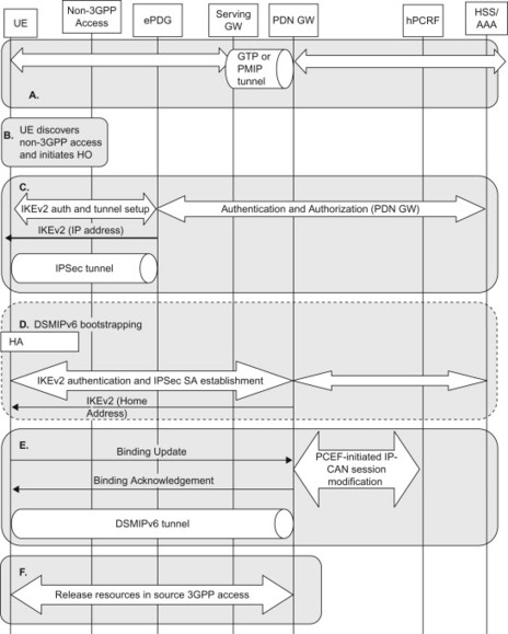
Figure 12.4.3.1.5 Handover from 3GPP access to untrusted non-3GPP access.
The message flow above illustrates a handover from a 3GPP access to an untrusted non-3GPP access. In case of handover from a 3GPP access to a trusted non-3GPP accesses using DSMIPv6 the procedure is similar with a few key differences:
-
The tunnel setup with ePDG in step B is not preformed. Instead, step B is replaced by an access authentication in the trusted non-3GPP access. The non-3GPP access also establishes a gateway control session with the PCRF via Gxx as part of step B.
-
When the path switch has taken place in step E, the PCRF may provide the trusted non-3GPP access with updated QoS rules via the Gxx reference point.
12.5 Bearer and QoS-related Procedures
12.5.1 General
As have been described in, Section 6.2, the 3GPP accesses use the concept of a ‘bearer’ to manage the QoS between the UE and the PDN GW. For E-UTRAN, the EPS bearer extends between the UE and the PDN GW (for GTP-based system) and the UE and Serving GW (for PMIP-based system). For GERAN and UTRAN, the bearers are implemented as PDP contexts between the UE and the SGSN. When GERAN and UTRAN are connected to the EPS, the PDP contexts get mapped to EPS bearers between SGSN and the PDN GW or Serving GW.
Each EPS bearer is associated with a well-defined QoS class described by the QCI as well as packet filters that determine which IP flows gets transported over that particular bearers. Certain bearers also have associated GBR and MBR parameters.
The bearers can be dynamically established, modified or removed depending on the needs of applications being used by the UE. In E-UTRAN, the dedicated bearer procedures are always initiated by the network. The UE may send a request for certain resources (QCI, bit rates, packet filters) to the network and this request can result in bearer operations being initiated by the network. In GERAN/UTRAN, the PDP context procedures are initiated by the network or by the UE.
Other accesses not defined by 3GPP, such as HRPD or WiMAX, may have similar procedures for allocating resources in the access network. The terminology may be different but the purposes of the procedures are roughly the same; that is, to set up a (logical) transmission path between the UE and the network to transport traffic with certain QoS requirements. The mechanisms and procedures used between the UE and the access network are specific to each access and will not be described in detail in this book. Using the PCC architecture, EPS is able to interwork with such access-specific procedures.
In this section, we will describe some of the dynamic procedures available in EPS to handle bearers for 3GPP accesses and how to interwork with the access-specific procedures available in other accesses.
12.5.2 Bearer procedures for E-UTRAN
12.5.2.1 Dedicated bearer activation
The dedicated bearer activation procedure is used when the network decides that a new dedicated bearer needs to be established. The procedure is initiated by the PDN GW (when using GTP-based S5/S8) or the Serving GW (when using PMIP-based S5/S8). The trigger is typically that the PDN GW/Serving GW has received new PCC/QoS rules from the PCRF that require a new dedicated bearer to be established. The reason for why the PCRF provided new PCC/QoS rules can, for example, be due to an Rx interaction, or that the UE has sent a UE-initiated resource request that was provided to the PCRF.
The procedure is shown in Figure 12.5.2.1.1 and is briefly described in the following steps.
-
The PCRF makes a policy decision because it received session information from an AF over the Rx interface or because it received a request for resources from the access network.
-
For a GTP-based system (A1), the PCRF sends the new PCC rules to the PDN GW. Based on the received PCC rules, the PDN GW decides to activate a new dedicated bearer and sends a Create Dedicated Bearer Request to the Serving GW.
-
For a PMIP-based system (A2), the PCRF sends the new QoS rules directly to the Serving GW. Based on the received QoS rules, the Serving GW decides to activate a new dedicated bearer.
-
-
The Serving GW sends a Create Dedicated Bearer Request to the MME.
-
The MME sends a command to the eNodeB to initiate the appropriate E-UTRAN procedures to establish an appropriate radio bearer. The appropriate reconfiguration of the RRC connection between UE and eNodeB is performed.
-
The MME acknowledges the bearer activation to the Serving GW by sending a Create Dedicated Bearer Response (EPS Bearer Identity, S1-TEID) message.
-
The Serving GW acknowledges the dedicated bearer setup.
-
For a GTP-based system (E1), the Serving GW sends a Create Dedicated Bearer Response to the PDN GW. The PDN GW sends an acknowledgement to the PCRF.
-
For a PMIP-based system (E2), the Serving GW sends an acknowledgement directly to the PCRF.
-
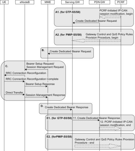
Figure 12.5.2.1.1 Bearer procedures.
12.5.2.2 UE-initiated resource request, modification and release
As described in, Section 8.1, there are two concepts for how QoS is allocated in the NW, either triggered by the network or triggered by an explicit request from the UE. The procedure described in this section supports the latter scenario where, for example, an application in the UE would like to have premium QoS and triggers the E-UTRAN interface in the UE to make a corresponding request to the network. The procedure can also be used when the UE wants to modify or release a previously granted resource. If accepted by the network, the request invokes either the dedicated bearer activation procedure, the dedicated bearer modification procedure or a dedicated bearer is deactivated. The flow diagram for this procedure is illustrated in Figure 12.5.2.2.1.
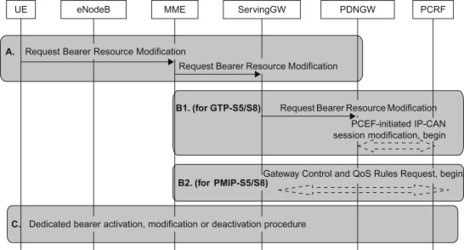
Figure 12.5.2.2.1 UE-initiated resource request, modification and release.
The procedure is briefly described in the following steps.
-
Based on, for example, application request, the UE sends a request for resource modification to the network. The UE may include packet filter information for the packet flows that are to be added, modified or deleted as well as associated QoS information (requested QCI and potentially a requested GBR). The MME forwards the request to the Serving GW.
-
For GTP-based system (B1), the request is forwarded to the PDN GW that in turn informs the PCRF about the request. For a PMIP-based system, the Serving GW informs the PCRF about the request, without involving the PDN GW.
-
The PCRF makes a policy decision and provides the policy decision to the PDN GW and potentially the Serving GW. Depending on the new, modified or deleted PCC/QoS rules, the PDN GW (for GTP-based S5/S8) or the Serving GW (for PMIP-based S5/S8) invokes the appropriate EPS bearer procedures.
12.5.3 Bearer procedures for GERAN/UTRAN
12.5.3.1 UE-initiated secondary PDP context establishment
When the UE is camped on GERAN or UTRAN, it uses the secondary PDP context activation procedure in order to establish a new PDP context for the same PDN connection. The procedure is triggered by the UE for similar reasons as the UE-initiated bearer resource modification procedure over E-UTRAN (see above).
The S4-SGSN maps between the PDP context procedures used over GERAN/UTRAN and the EPS bearer procedures used towards the Serving GW and PDN GW. As can be seen below, the S4-SGSN maps from the secondary PDP context activation/modification procedure to a UE-initiated bearer resource modification procedure over S4.
The procedure is shown in Figure 12.5.3.1.1 and is briefly described in the following steps.
-
Based on, for example, application request, the UE sends a secondary PDP context activation request. The S4-SGSN maps this into a UE-initiated bearer resource modification request and sends it to the Serving GW.
-
For GTP-based system (B1), the request is forwarded to the PDN GW that in turn informs the PCRF about the request. For a PMIP-based system, the Serving GW informs the PCRF about the request, without involving the PDN GW. The PCRF makes a policy decision and replies to the PDN GW or the Serving GW.
-
Depending on the new, modified or deleted PCC/QoS rules, the PDN GW (for GTP-based S5/S8) or the Serving GW (for PMIP-based S5/S8) invokes the appropriate EPS bearer procedures. In this case, the UE has requested a new PDP context; this means that the PDN GW (or Serving GW in PMIP case) must initiate the establishment of a new dedicated EPS bearer in order to maintain the 1:1 mapping between PDP contexts and EPS bearers. When the S4-SGSN receives the Create Dedicated Bearer Request, it initiates the appropriate GERAN or UTRAN procedures. The S4-SGSN also completes the procedure towards the Serving GW.
-
The S4-SGSN responds to the UE with an Activate Secondary PDP Context Response.
-
The Serving GW completes the dedicated bearer procedure.
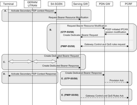
Figure 12.5.3.1.1 Secondary PDP context activation (UE-initiated).
12.5.3.2 Network requested secondary PDP context activation
The network requested secondary PDP context activation procedures for GERAN/UTRAN correspond to the network-initiated dedicated bearer procedures for E-UTRAN. This means that it is the network that decides to establish a new PDP context. There is however one key difference between the GERAN/UTRAN and the E-UTRAN procedures. With E-UTRAN, the network-initiated bearer procedures are the ‘native’ bearer procedures. A UE-initiated bearer resource modification request over E-UTRAN is not a bearer procedure as such, but may trigger a network-initiated bearer procedure. With GERAN/UTRAN, it is the other way around. The secondary PDP context procedures are UE-initiated as illustrated in the previous section. As shown in this section, the network may trigger such a procedure by sending a request to the UE for activating a secondary PDP context.
Similar to the UE-initiated procedures in the previous section, it is the SGSN that maps between PDP context procedures and EPS bearer procedures.
The procedure is shown in Figure 12.5.3.2.1 and is briefly described in the following steps.
-
Based on trigger from the PCRF, the PDN GW (for GTP-S5/S8) or Serving GW (for PMIP-S5/S8) decides to establish a new dedicated bearer. In case of GTP-S5/S8, the PDN GW sends a Create Dedicated Bearer Request message to the Serving GW. In case of PMIP-S5/S8, the PCRF interacts directly with the Serving GW.
-
The Serving GW sends the Create Dedicated Bearer Request message to the S4-SGSN. The S4-SGSN maps this into request fro the UE to activate a secondary PDP context.
-
The UE initiates the secondary PDP context activation procedure. The appropriate RAN procedures are performed and the S4-SGSN responds to the UE.
-
The S4-SGSN also responds to the Serving GW when the dedicated bearer (i.e. the secondary PDP context) has been activated.
-
For GTP-based S5/S8, the Serving GW forwards the response to the PDN GW that in turn may inform the PCRF. For PMIP-based S5/S8, the Serving GW responds to the PCRF directly.
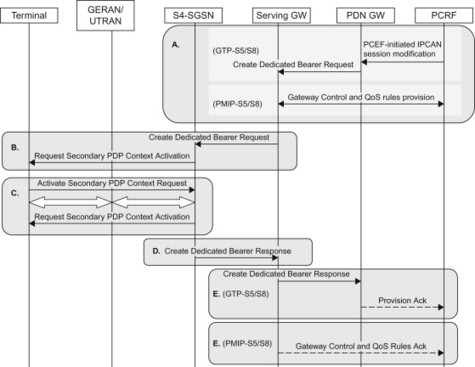
Figure 12.5.3.2.1 Network requested secondary PDP context activation.
12.5.4 Interworking with dynamic QoS mechanisms in other accesses
12.5.4.1 Network-initiated resource provision
The QoS procedures in the non-3GPP access network depend on the particular access technology being used. EPS defines generic procedures that can be used to interwork with different non-3GPP accesses. In this section, we illustrate a network-initiated QoS reservation procedure, similar to the network-initiated dedicated bearer and PDP context activation procedures illustrated above. The interface between the UE and the access network is however not described since it varies between the accesses (Figure 12.5.4.1.1).
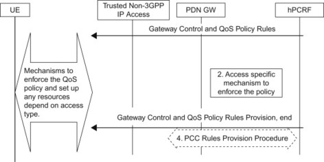
Figure 12.5.4.1.1 Network-initiated resource provision.
12.6 Single Radio Voice Call Continuity
As described in Chapter 5 the SRVCC is a solution that addresses the problem that there may not be full coverage for MMTel VoIP services used on E-UTRAN. SRVCC solves this problem by offering a mechanism where the UE performs a coordinated radio level handover in combination with a change from IMS VoIP to circuit-switched voice using IMS procedures for service continuity.
The details of SRVCC and the related procedures spans outside the EPS into IMS and the CS core network. This chapter will outline the SRVCC procedure and the impact on the EPC network on a high level without going too far into the details of other parts of the system. The 3GPP TS 23.216, [23.216] elaborates more on the SRVCC procedure and impacts the EPC while the 3GPP TS 23.237 [23.237] details how the IMS handles service continuity.
The solutions for SRVCC towards GERAN/UTRAN and SRVCC towards CDMA are not exactly the same due to the differences in the interworking of EPS with CDMA and GERAN/UTRAN, respectively.
12.6.1 SRVCC from E-UTRAN to GERAN or UTRAN
SRVCC impacts the eNodeB, the MME and the MSC Server and requires service continuity support in the IMS. A new interface, Sv, has been specified between the MME and the MSC to execute the actual handover. Prerequisites for SRVCC are that both the UE and the EPS are SRVCC capable and that the session is anchored in a Service Centralization and Continuity Application Server (SCC AS) in the IMS. To illustrate the SRVCC functionality, we will examine an example of a call between two UE’s where UE-A will experience an SRVCC. A simplified picture of the call path between two UE’s before SRVCC is performed is shown in Figure 12.6.1.1.
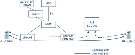
Figure 12.6.1.1 Before SRVCC execution.
In the example, the UE-A and UE-B are using IMS voice telephony to communicate. Only the most relevant nodes are shown. The IMS signalling traverses the IMS control nodes and is anchored in an SCC AS in UE-A’s network. The IMS voice packets are sent end-to-end between the UEs using the EPS IP connectivity through eNodeB and Serving/PDN GW (the details on how the IMS voice packets are sent to UE-B are note relevant for this discussion).
When UE-A moves in the network, it may reach a point where there the LTE coverage will diminish and an SRVCC handover must be performed to GERAN CS or UTRAN CS. When the LTE signal strength decreases, the UE will measure on neighbour cell to discover suitable HO candidates and report the measurements to the eNodeB. Based on the bearer QCI and configured knowledge of to which cells SRVCC is necessary, the eNodeB can trigger an SR VCC HO if PS handover is not possible.
The MME is informed by the eNodeB that SRVCC HO is needed via the handover request from eNodeB with the indication that this is for SRVCC handling. The MME then triggers the SRVCC procedure with the MSC Server via the Sv interface (the address of the MSC is provisioned to the MME). The MME also passes a special routing number that allows the MSC Server to establish a session with the IMS SCC AS. The MSC Server initiates the session transfer procedure to IMS and coordinates it with the CS handover procedure to the target cell. The MSC Server sends a response to the MME, which includes the necessary CS HO command information for the UE to access the target UTRAN/GERAN cell. The MME sends a handover command to the eNodeB that passes it to the UE. As a next step, the UE tunes into the GERAN/UTRAN cell and in principle experience a CS HO in the target cell where the UE will receive a CS telephony bearer. After the HO, the UE-A will be connected with CS telephony to the MSC Server. The MSC Server interworks the CS telephony used by UE-A to the IMS MMTel voice service used by UE-B as shown in Figure 12.6.1.2.
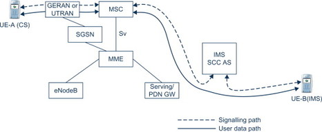
Figure 12.6.1.2 After SRVCC handover.
IMS voice telephony can also be supported on WCDMA/HSPA. Hence, a similar solution for SRVCC from IMS voice telephony to GERAN or UTRAN CS telephony is also specified in 3GPP. The only differences are that the SGSN takes the role of the MME and UTRAN performs the same functionality as the eNodeB in E-UTRAN.
For more details on the SR VCC solutions see 3GPP TS 23.216, [23.216] and TS 23.237 [23.237].
12.6.2 SRVCC from E-UTRAN to 1xRTT
The architecture for SRVCC between IMS voice telephony on E-UTRAN to CS telephony on 1xRTT is shown in Figure 12.6.2.1.
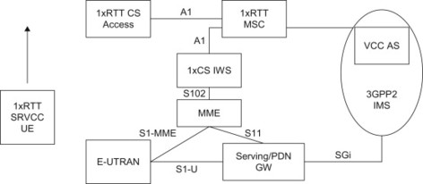
Figure 12.6.2.1 SRVCC to 1xRTT architecture.
The architecture for SRVCC between IMS voice telephony on E-UTRAN to CS telephony on 1xRTT looks similar to the one for SRVCC to GERAN and UTRAN, but there are a few key differences. Instead of an Sv interface between the MME and the interface to trigger handovers, there is a different type of mechanism employed. The UE communicates directly with the 1xRTT MSC using NAS message tunnelling. The MME is in principle just a signalling relay and the interworking function tunnels the signalling messages and interworks them towards the 1xRTT MSC. This allows the UE to communicate with the 1xRTT MSC to trigger the service continuity procedure in IMS and to prepare the access before performing the handover on the radio layer. For details on the SRVCC solution for 1xRTT, refer to 3GPP TS 23.216, [23.216] and 3GPP2 TS X.S0042-0, [X.S0042].
12.7 CS Fallback
The main idea behind CS fallback is to allow UEs to camp on LTE and utilize the LTE for data services but reuse the GSM, WCDMA or CDMA network for circuit-switched voice services. The CS fallback feature was described briefly in Chapter 5.
To support CS fallback, there is a set of modifications of existing procedures and also some additional CS fallback specific procedures added to EPS. This section intends to illustrate the main principles of the CS fallback procedures by outlining an example of a CS fallback call.
There are special additions to the attach and TA update procedures which activates an interface, called SGs, between the MME and the MSC. This interface is used by the MSC to send paging messages for CS calls to the UE camping on LTE.
The procedure is shown in Figure 12.7.1 and is briefly described in the following steps.
-
The MSC receives an incoming voice call and sends a CS page to the MME over a SGs interface. The MME uses the TMSI (or IMSI) received from the MSC to find the S-TMSI (which is used as the paging address on the LTE radio interface). The MME forwards the paging to the eNodeB in the TAs where the UE is registered. The eNodeBs perform the paging procedures in all the cells in the indicated TAs. The paging message includes a special CS indicator that informs the UE that the incoming paging is for a terminating CS call.
-
At the reception of the paging message, the UE performs a service request procedure which establishes the RRC connection and sends the Service Request to the MME. The Service Request message includes a special CS fallback indicator that informs the MME that the CS fallback is needed. This triggers the MME to activate the bearer context in the eNodeB with an indication to perform fallback to GERAN or UTRAN.
-
The eNodeB selects a suitable target cell, possibly by triggering the UE to send measurements on neighbour cells, and initiates a handover or cell change procedure. The selection between handover or cell change procedure is based on the target cell capabilities and is configured in the eNodeB.
-
After handover/cell change, the UE detects the new cell and establishes a radio connection and sends a page response to the MSC, via the target RAN.
-
When the page response arrives at the MSC, a normal mobile terminated call setup continues and the CS call is activated towards the UE.
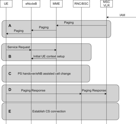
Figure 12.7.1 Mobile terminating call in idle mode.
The CS fallback specifications cover all necessary procedures to support fallback to GSM, WCDMA and 1xRTT for mobile originated and mobile terminating calls in both idle and active mode. The procedures for CS fallback are specified in 3GPP TS 23.272, [23.272].
Even though CS fallback was primarily introduced to support voice calls it also supports other CS services. In particular the support for SMS has been specified in such a way that it does not require the UE to switch to another radio interface. The UE can remain on LTE and still send and receive SMS. The SMS messages are tunnelled between the UE and the MSC through the MME NAS signalling and the SGs interface.