Flow control for fully adaptive routing†
Abstract
Routing algorithms for cache-coherent networks-on-chip have only limited virtual channels (VCs) at their disposal, which poses challenges for the design of routing algorithms. Existing fully adaptive routing algorithms apply conservative VC reallocation: only empty VCs can be reallocated, which limits performance. We propose two novel flow control designs. First, whole packet forwarding reallocates a nonempty VC if the VC has enough free buffers for an entire packet. Whole packet forwarding does not induce deadlock if the routing algorithm is deadlock-free using conservative VC reallocation. It is an important extension to several deadlock avoidance theories. Second, we extend Duato’s theory to apply aggressive VC reallocation on escape VCs without deadlock. Finally, we propose a design which maintains maximal routing flexibility with low hardware cost. For synthetic traffic, our design performs, on average, 88.9% better than existing fully adaptive routing. Our design is superior to partially adaptive and deterministic routing.
6.1 Introduction
The performance of networks-on-chip (NoCs) is sensitive to the routing algorithm, as it defines the network latency and saturation throughput [7, 35]. Many novel NoC routing algorithms have been proposed to deliver high performance [18, 20, 23, 28, 31, 46, 55]. In addition to performance considerations, the routing algorithm has correctness implications; any routing algorithm must be deadlock-free at both the network level and the protocol level. The guarantee of network-level deadlock freedom is generally based on deadlock avoidance theories. There are many theories for fully adaptive routing design [12, 13, 17, 29, 44, 48, 52, 53] and partially adaptive routing design [4, 6, 18, 19]. Although most theories were originally proposed for off-chip networks, they are widely used in today's NoCs [18, 20, 23, 28, 31, 46, 55].
However, NoC packets are quite different from off-chip network packets. Abundant wires lead to wider flits, which decreases the flit count per packet; short packets dominate the NoC traffic. In contrast, the wires in off-chip networks are limited by pin counts; the flit width of a typical off-chip router is of the order of 32 bits (e.g., Alpha 21364 router [37]), while the typical NoC flit width is between 128 bits [21] and 256 bits [10]. With such wide flits, coherence messages with an address and control information but no data are encoded as single-flit packets (SFPs). Figure 6.1 shows that, on average, 78.7% of packets are single-flit control ones for PARSEC workloads [3]; other data packets are five flits long with a 64-bit full cache line.

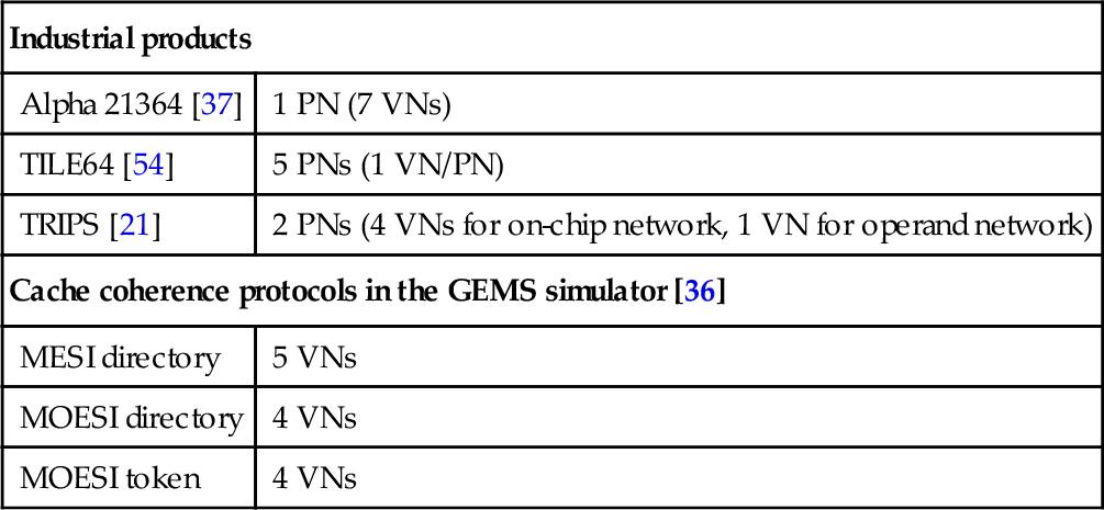
Another noteworthy difference is that the NoC buffers are more expensive than the off-chip network ones owing to the tight area and power budgets [16, 22]; thus, NoCs generally use flit-based wormhole flow control [9]. Although buffers are limited, several physical networks or virtual networks (VNs) are needed for delivering different messages to avoid protocol-level deadlock. Table 6.1 lists the number of physical networks and VNs in some off-chip and on-chip networks. We also show the VN counts for some coherence protocols in the GEMS simulator [36]. Typically, four or five VNs are needed to avoid protocol-level deadlock. Considering the expense of NoC buffers and large allocators, each VN will have only a small number of virtual channels (VCs) [5]. For example, the TILE64 [54] and TRIPS [21] processors have one VC per VN. Thus, an NoC routing algorithm generally runs with limited VCs.
Table 6.1
Number of Physical Networks (PNs)/Virtual Networks (VNs)
| Industrial products | |
| Alpha 21364 [37] | 1 PN (7 VNs) |
| TILE64 [54] | 5 PNs (1 VN/PN) |
| TRIPS [21] | 2 PNs (4 VNs for on-chip network, 1 VN for operand network) |
| Cache coherence protocols in the GEMS simulator [36] | |
| MESI directory | 5 VNs |
| MOESI directory | 4 VNs |
| MOESI token | 4 VNs |
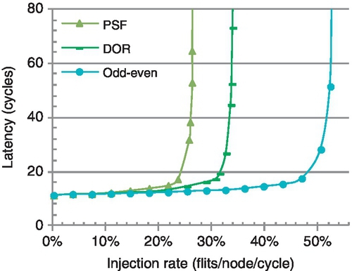
In VC-limited NoCs with short packets dominating traffic, the design of fully adaptive routing faces new challenges. In a wormhole network, fully adaptive routing algorithms based on existing theories require conservative VC reallocation: only empty VCs can be reallocated [12, 13, 17, 29, 44, 48, 52, 53]. This scheme prevents network-level deadlock, but it is very restrictive with many short packets [18]. Figure 6.2 shows the performance of three algorithms.1 Despite its flexibility and load-balancing capability, the fully adaptive algorithm is inferior to the deterministic and partially adaptive ones, since the latter algorithms apply aggressive VC reallocation. It is imperative to enhance the design of fully adaptive routing.
This chapter focuses on improving fully adaptive routing algorithms by designing novel flow control. We propose two mechanisms. First, whole packet forwarding (WPF) allows a nonempty VC which has enough buffers for an entire packet to be reallocated. WPF can be viewed as applying packet-based flow control in a wormhole network. We prove that a fully adaptive routing algorithm using WPF is deadlock-free if this algorithm is deadlock-free with conservative VC reallocation. The proposed WPF is an important extension to previous deadlock avoidance theories. Second, we extend Duato's theory [12] to apply aggressive VC reallocation on escape VCs (EVCs) without deadlock. This extension further improves the VC utilization and the network performance.
The novel flow control enables the design of a fully adaptive routing algorithm with high VC utilization and maximal routing flexibility. Compared with existing fully adaptive routing algorithms, our design provides an average gain of 88.9% for synthetic traffic, and an average speedup of 21.3% and a maximal speedup of 37.8% for PARSEC workloads that heavily load the network. It is also superior to partially adaptive and deterministic algorithms.
In this chapter we make the following main contributions:
• We propose WPF to improve the performance of fully adaptive routing algorithms.
• We demonstrate WPF is an important extension to existing deadlock avoidance theories.
• We extend Duato's theory to apply aggressive VC reallocation on EVCs without deadlock.
• We propose an efficient design which maintains high routing flexibility with low overhead.
6.2 Background
Here, we discuss related work in deadlock avoidance theories and designs for fully adaptive routing.
6.2.1 Deadlock avoidance theories
Since NoCs typically use wormhole flow control [7, 9, 35, 41], we focus on theories for wormhole networks. Dally and Seitz [6] proposed a seminal deadlock avoidance theory to design deterministic and partially adaptive routing algorithms. Duato [12, 13] introduced the routing subfunction, and gave an efficient design method. The message flow model [29] and channel waiting graph [44] were used to analyze deadlock. Taktak et al. [48] and Verbeek and Schmaltz [52] leveraged the decision procedure to establish deadlock freedom. This method can also be applied to our designs. Verbeek and Schmaltz [51, 53] gave the first static necessary and sufficient condition for deadlock-free routing. These theories [12, 13, 17, 29, 44, 48, 52, 53] can be used to design fully adaptive routing algorithms.
The theories of fully adaptive routing algorithms require only empty VCs to be reallocated. This requirement guarantees that all blocked packets can reach VC heads to access “deadlock-free” paths. Yet, it limits performance with many short packets. Some deadlock-recovery designs [1] or theories [14] remove this limitation. They allow the formation of deadlock, and then invoke some recovery mechanisms. In contrast, we extend deadlock avoidance theories to prohibit the formation of deadlock.
There are several partially adaptive routing algorithms based on turn models [4, 18, 19]. They allow aggressive VC reallocation: a VC can be reallocated once the tail flit of the last packet has arrived [6, 8]. This property can be deduced from Dally and Seitz's theory [6] since the channel dependency graphs of these algorithms are acyclic. However, partially adaptive routing algorithms suffer from limited adaptivity: packets cannot use all minimal paths between the source and the destination.
6.2.2 Fully adaptive routing algorithms
Duato's theory [12] is widely used to design fully adaptive routing algorithms. This theory classifies the network VCs into EVCs and adaptive VCs (AVCs). EVCs apply more restrictive algorithms, typically dimensional order routing (DOR), to form deadlock-free paths. An EVC can only be used when the port adheres to DOR.
Many fully adaptive routing algorithms based on Duato's theory [20, 31, 37, 55] select the physical port first. Once a port has been selected, packets can request only VCs of this chosen port. This requirement imposes a limitation: if a packet enters an EVC, it can only use EVCs until it is delivered. Otherwise, EVCs may be involved in deadlock. In VC-limited NoCs, this limitation easily induces adaptivity loss. However, Duato's theory supports the design of algorithms which can use AVCs after using an EVC if packets can always request EVCs [12]. On the basis of these observations, we propose a design which maintains high routing flexibility with low hardware cost.
6.3 Motivation
In this section, we analyze the requirements and limitations of fully adaptive routing algorithms. We also illustrate how these requirements negatively affect performance.
6.3.1 VC reallocation
Fully adaptive routing has the limitation that only empty VCs can be reallocated. This requirement is reasonable since VCs may form cycles in fully adaptive routing. For example, Duato's theory arbitrarily uses AVCs [12]; if multiple packets reside in one VC, a deadlock configuration appears, as shown in Figure 6.3. Here each VN has two VCs: an AVC and an EVC. Configuring more VCs cannot eliminate this deadlock scenario since cycles exist among AVCs.

Figure 6.3 involves eight packets: P0-P7. P0's head flit is behind P1's tail flit in AVC1. The same is true for P1, P2, P4, P5, and P6. Although the head flits of P3 and P7 are at VC heads, they cannot move as both AVC0 and EVC0 are occupied. This deadlock scenario occurs because some head flits are not at VC heads, resulting in some packets being unable to access the “deadlock-free” path. Also, the tail flits of these packets reside in other VCs, prohibiting other packets from reaching VC heads. These following packets then cyclically block the aforementioned packets. For example, P0's tail flit resides in AVC0, blocking P3 from using this VC, which cyclically blocks P0. If the packet length is greater than the VC depth, putting multiple packets in one VC may induce deadlock. Yet, we notice that moving entire short packets into nonempty VCs will not prevent following packets from reaching VC heads. This is an opportunity for optimization, especially with many short NoC packets.
6.3.2 Routing flexibility
This section discusses routing flexibility in VC-limited NoCs. Many fully adaptive algorithms based on Duato's theory consist of the routing function and selection strategy [20, 31, 37, 55]; they are called port-selection-first (PSF) algorithms since once the selection strategy has chosen a port, the packet requests VCs of only this particular port. If we have a separable VC allocator with two stages of arbiters [2, 38, 42], a PSF algorithm only needs V:1 arbiters in the first stage as shown in Figure 6.4a.

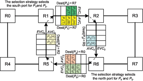
A limitation of these algorithms is that once a packet enters an EVC, it must continue to use EVCs; the packet loses adaptivity in subsequent hops. Violating this limitation induces deadlock as shown in Figure 6.5. If P1 and P2 select the south port, they can request only AVC2 since EVC2 can be requested only when the port adheres to DOR. Similarly, P4 and P5 select the north port; they request only AVC0. No packet can move. Thus, requiring that if a packet enters an EVC it can use only EVCs subsequently if necessary for PSF algorithms. However, this requirement results in significant adaptivity loss with limited VCs.
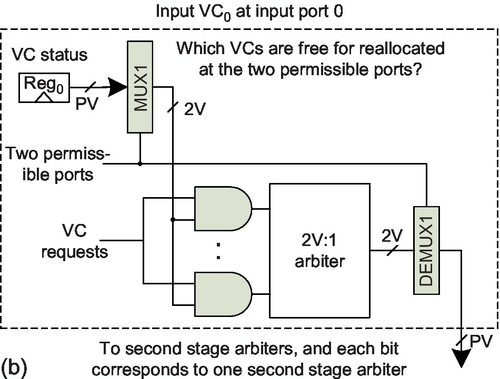
Duato's theory supports algorithms using AVCs after using EVCs, if they guarantee packets are always able to request EVCs. To achieve this target, a packet could request all permissible output VCs, since at least one port must adhere to DOR and the packet can use the EVC of this port [12]. However, this naive design has additional overhead. As shown in Figure 6.4b, the VC allocator uses 2V:1 arbiters to cover the at most two permissible ports for minimal routing algorithms in the first stage. We propose a low-cost design to maintain high routing flexibility.
6.4 Flow control and routing designs
First, we present WPF and prove that it is deadlock-free. Then, we extend Duato's deadlock avoidance theory to apply aggressive VC reallocation on EVCs. Next, we provide a low-cost design to maintain routing flexibility. Finally, we describe the implementation and overhead.
6.4.1 Whole packet forwarding
We propose WPF. Suppose a packet Pk with length(Pk) resides in VCi, and VCj is downstream of VCi. Assume the routing algorithm allows Pk to use VCj. With conservative VC reallocation, VCj can be reallocated to Pk only if the tail flit of its last allocated packet is sent out, i.e., it is empty [8]. For WPF, VCj can be reallocated if it has received the tail flit of the last allocated packet, and its free buffer count is no less than length(Pk).
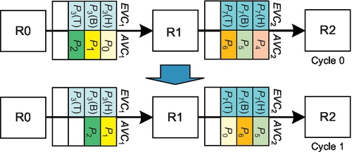
Figure 6.6 shows a WPF example. The algorithm allows P1 to use VC2. VC2 received P2's tail flit and has two free slots; this space is enough for P1's two flits. Thus, WPF reallocates VC2 to P1. WPF works similarly to packet-based flow control such as store-and-forward flow control [15] and virtual cut-through (VCT) flow control [26]. VCT enables the design of high-frequency routers [43]. Yet, our design uses wormhole flow control with empty VCs, which does not require the empty VC to be large enough for entire packets; this reduces the buffering requirement compared with VCT flow control, and provides more flexibility.

Our contention is that if the routing algorithm with conservative VC reallocation is deadlock-free, then applying WPF will not induce deadlock. Intuitively, this contention is true, since short packets will be either at VC heads or behind some packets whose head flits are at VC heads. Thus, some packets can access the “deadlock-free” path. Yet, the “deadlock-free” path is coupled to special theories. We provide a general proof. We label the algorithm with conservative VC reallocation as Alg; Alg + WPF is Alg with WPF to forward entire packets into nonempty VCs. The proof needs a simple assumption about the router.
This assumption provides weak fairness among permissible VCs. It can be fulfilled in the following manner. The router continually monitors the status of all downstream VCs. If one permissible VC is available, the packet requests it immediately. If the algorithm first selects a port and limits the packet to request VCs of the selected port, the selection strategy should guarantee that any permissible port has some possibility to be selected. As shown in Section 6.4.4, common NoC routers adhere to Assumption 6.1.
Theorem 6.1
If Alg is deadlock-free, then Alg + WPF is also deadlock-free.
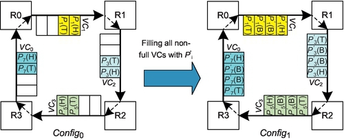
Informal description: We prove this theorem by contradiction. We prove that if Alg + WPF has a deadlock configuration, then Alg has a deadlock configuration as well. Using Config0 in Figure 6.7 as an example, we remove packets whose head flits are not at VC heads, and get a new configuration Config1. We prove that Alg can achieve Config1, and Config1 is a deadlock configuration. However, Alg is deadlock-free; thus, there is no such configuration.

Proof: By contradiction. If Alg + WPF is not deadlock-free, then there is a deadlock configuration (Config0) in which a set of packets, ![]() , is waiting on VCs held by other packets in
, is waiting on VCs held by other packets in ![]() . We prove that there is a deadlock configuration for Alg in three steps.
. We prove that there is a deadlock configuration for Alg in three steps.
Step 1: We build a new configuration based on Config0. Consider each packet Pi in ![]() . If Pi's head flit is not at the VC head, then this VC was allocated to Pi using WPF; all flits of Pi must reside in one VC. We remove Pi and label these removed packets as
. If Pi's head flit is not at the VC head, then this VC was allocated to Pi using WPF; all flits of Pi must reside in one VC. We remove Pi and label these removed packets as ![]() . We label the new configuration as Config1, and the set of packets in Config1 as
. We label the new configuration as Config1, and the set of packets in Config1 as ![]() .
.
Step 2: We prove that when the network is routed by Alg, all packets in ![]() can move into their current VCs in Config1. For each packet Pj in
can move into their current VCs in Config1. For each packet Pj in ![]() , we consider each hop hopk of Pj when it is routed by Alg + WPF. We assume that Pj's head flit moves into VCk during hopk. There are two situations:
, we consider each hop hopk of Pj when it is routed by Alg + WPF. We assume that Pj's head flit moves into VCk during hopk. There are two situations:
(1) VCk is empty when Pj reaches it; VCk is allocated to Pj with conservative VC reallocation. Thus, when it is routed by Alg, Pj can use VCk.
(2) VCk is not empty when Pj reaches it; VCk is allocated to Pj with WPF. The algorithm allows Pj to use VCk. Yet, when it is routed by Alg, Pj cannot move into VCk until it is empty. Since Alg is deadlock-free, the packet currently in VCk must move out in a limited time. Then VCk is available for conservative VC reallocation. On the basis of Assumption 6.1, Pj has some possibility to request VCk. Then, Pj can move into VCk. Thus, when it is routed by Alg, Pj can use VCk.
If we consider situations 1 and 2 together, and take into account that the head flits of all packets in Config1 are at VC heads, if a VC is used by Pj during any hop when it is routed by Alg + WPF, this VC can also be used by Pj when it is routed by Alg. Thus, Pj can be routed to its current VC(s) in Config1 by Alg.
Step 3: We prove that Config1 is a deadlock configuration for Alg. For each Pi in the removed set ![]() , all flits of Pi reside in one VC but Pi's head is not at the VC head. Thus, removing Pi does not create empty VCs. Alg uses conservative VC reallocation, which reallocates only empty VCs; all packets in
, all flits of Pi reside in one VC but Pi's head is not at the VC head. Thus, removing Pi does not create empty VCs. Alg uses conservative VC reallocation, which reallocates only empty VCs; all packets in ![]() still wait for VCs held by other packets in
still wait for VCs held by other packets in ![]() . Config1 is a deadlock configuration for Alg. But Alg is deadlock-free, so there is no deadlock configuration. Thus, Alg + WPF is deadlock-free as well.
. Config1 is a deadlock configuration for Alg. But Alg is deadlock-free, so there is no deadlock configuration. Thus, Alg + WPF is deadlock-free as well.
This proof needs only a simple assumption. WPF can be used with many fully adaptive routing algorithms if they are deadlock-free with conservative VC reallocation. It is an important extension to existing theories [12, 13, 17, 29, 44, 48, 52, 53]. In the Appendix, we further prove that if Alg + WPF is deadlock-free, Alg is also deadlock-free.
6.4.2 Aggressive VC reallocation for EVCs
We apply WPF to fully adaptive algorithms designed on the basis of Duato's theory [12]. Yet, using WPF directly may bring about fairness issues for long packets, as shown in Figure 6.8. Both three-flit packet P3 and SFP P0 are waiting to move forward. The free buffers in EVC2 and AVC2 allow P0 to move. P3 must wait for EVC2 or AVC2 to have three free slots, or for them to be empty. If P4 moves forward in the next cycle, a similar situation happens again: the free buffers in EVC2 or AVC2 allow only P1 to move. Under the extreme case, P3 will be permanently waiting if SFPs are continuously injected into AVC1.2
A design to address this fairness issue is to deploy a time counter and a priority allocator. Once the counter crosses the threshold value for the blocked packet P3, a high priority is assigned to P3's VC allocation so as to prevent SFPs from occupying the buffers in EVC2 and AVC2. This design involves additional costs, including those for the time counter and the priority allocator. Also, an appropriate threshold value needs to be configured to provide the desired fairness.
Instead of using this complex design, we leverage a more elegant observation. We notice the EVCs in Duato's theory can apply aggressive VC reallocation without deadlock. With aggressive reallocation, P3 and P0 can equally use EVC2; P3 cannot be blocked forever. Under the worst case with a stream of continuous short packets using AVC2, P3 cannot acquire AVC2; this may cause long packets to have less adaptivity than short ones. Yet, two factors mitigate the possible negative effect. First, network streams generally consist of both short and long packets. Second, our routing design in Section 6.4.3 can request AVCs after using EVCs; thus, this limitation causes only minor adaptivity loss. Also, our design has less overhead than the complex design, and aggressive VC reallocation further improves the VC utilization and performance. This design is coupled to Duato's theory; we reiterate some definitions from Duato's paper [12, 13] to make this section self-contained.
Duato's necessary and sufficient theory [13] defines the direct cross and indirect cross dependency. Our research is mainly based on Duato's necessary theory [12]; thus, we omit these two types of dependency.
The routing subfunction is defined on EVCs. As the extended VC dependency graph is acyclic, we can assign an order among EVCs so that if there is a direct or an indirect dependency from EVCi to EVCj, then EVCi > EVCj [12]. Moreover, since the routing subfunction is connected, any packet can move to its destination by using EVCs [12].
Theorem 6.1 applies WPF to both AVCs and EVCs. In this section we further apply aggressive VC reallocation to EVCs. We label the deadlock-free algorithm based on Duato's theory with conservative VC reallocation as Alg; Alg + WPF + Agg is Alg with WPF for AVCs and aggressive VC reallocation for EVCs. We prove Theorem 6.3.
Theorem 6.3 extends Dauto's theory to apply aggressive VC reallocation on EVCs. It not only addresses the fairness issue of WPF on long packets, but also yields additional VC utilization and performance gains.
6.4.3 Maintain routing flexibility
In this section we propose a low-cost design to maintain high routing flexibility. This design is based on Duato's theory [12]. The design should allow the use of AVCs after the use of EVCs. Otherwise, once a packet enters EVCs, it will lose adaptivity in subsequent routing. The design must guarantee that a packet can request an EVC at any time [12]. Once this condition is satisfied, packets can always find a path which is not involved in cyclic dependencies, since the extended dependency graph of EVCs is acyclic [12].
In PSF algorithms, the only time a packet cannot use EVCs is when the selected port violates DOR. We make a simple modification by violating the selection in this case; the packet requests the EVC of the nonselected permissible port in addition to AVCs of the selected one. We use P1 in Figure 6.5 as an example. If the south port is selected, our design allows P1 to request the EVC of the east port. If there is only one permissible port, this port must adhere to DOR, and the packet can request its EVC. This design guarantees that a packet can always request an EVC. It allows a packet to move back into AVCs after using an EVC. Also, it needs only V:1 arbiters in the first stage of the VC allocator. Large arbiters result in more hardware overhead and introduce additional delay in the critical path.
6.4.4 Router microarchitecture
The pipeline of a canonical NoC router consists of routing computation, VC allocation, switch allocation, and switch traversal [8, 15, 38, 42]. We apply several optimizations. The speculative allocation parallelizes switch allocation with VC allocation at low loads [42]. Lookahead routing calculates at most two permissible ports one hop ahead and the selection strategy chooses the optimal one [20, 27, 31]. The router delay is two cycles plus one cycle for link traversal.
This baseline router adheres to Assumption 6.1 in Section 6.4.1. First, a common selection strategy guarantees that any permissible port can be selected. For example, in Section 6.5 we use a strategy which prefers the port with more free buffers. This strategy will not prohibit any permissible port from being selected since once the permissible ports have equal free buffers, it randomly selects one from them. Second, the router continually monitors the status of all downstream VCs using credits [8]. If one permissible VC of the selected port is eventually available, the packet can find out this situation, and requests this VC immediately. Therefore, an NoC router generally provides weak fairness among permissible VCs, even when selecting the port first.
Our design requires only simple modifications to the VC allocator. Any type of allocator can be used; we assume a low-cost separable allocator which consists of two stages of arbiters [2, 38, 42]. We modify the first-stage arbiters to apply WPF on AVCs and aggressive VC reallocation on EVCs. WPF requires calculating whether the free buffers are enough for an entire packet, which has some overhead. Yet, considering cache coherence packets exhibit a bimodal distribution and the majority are SFPs, we apply WPF only on SFPs.
Figure 6.9 shows the proposed VC allocator. Reg0 and Reg1 record whether a downstream VC can be reallocated. If a downstream VC is an AVC, the corresponding bit in Reg0 records whether it can be reallocated with conservative reallocation. If a downstream VC is an EVC, the corresponding bit in Reg0 records whether it can be reallocated with aggressive reallocation. The criterion is that the VC holds the tail flit of its last allocated packet and still has free buffers. Reg1 records whether a VC can be reallocated with WPF for SFPs. Its criterion is the same as applying aggressive VC reallocation on SFPs. Thus, we use Reg0 or Reg1 on the basis of the incoming packet type. If it is an SFP, we apply WPF, sending Reg1 to MUX1. Otherwise, Reg0 is sent to MUX1. Updates to Reg0 and Reg1 are off the critical path as the router monitors the status of downstream VCs. The increased delay is an additional two-input multiplexer: MUX0.

To maintain routing flexibility, we modify MUX1 and DEMUX1, as shown in Figure 6.9. MUX1 needs two additional signals: DOR and the other output port. The DOR signal indicates if the selected port obeys DOR. The other output port signal records the nonselected permissible port. The routing logic produces these signals. If DOR is “0,” the selected port violates DOR. Then, the status of the EVC for the other output port rather than the selected one is sent to the V:1 arbiter. This is accomplished with a two-input multiplexer whose control signal is DOR. DEMUX1 also needs these signals. If DOR is “0,” the result from the V:1 arbiter is demultiplexed to the second-stage arbiter for the EVC of the other output port. This is accomplished with a two-input demultiplexer. The increased delay is an additional two-input multiplexer and demultiplexer.
We implement the three VC allocators (Figures 6.4 and 6.9) in RTL Verilog for an open-source NoC router [2] and synthesize in Design Compiler with a Taiwan Semiconductor Manufacturing Company 65 nm standard cell library. The designs operate at 500 MHz under normal conditions (1.2 V, 25 °C). We use round-robin arbiters [8]. This router has five ports (P = 5) and four VNs; each VN has two VCs (V = 2). Table 6.2 gives the area and critical path delay estimates. The naive design uses 4:1 arbiters in the first stage, resulting in a 7.9% longer critical path and 13.4% more area than the PSF design. Our design uses 2:1 arbiters in the first stage and increases the critical path by only 0.5% and the area by only 0.2%. An allocator's power consumption is largely decided by the arbiter size [2, 55]; given the small arbiters in our design, there should be negligible power overhead compared with the PSF design.
Table 6.2
The Critical Path Delay and Area Results
| Design | Delay (ns) | Area (μm2) |
| PSF design (Figure 6.4a) | 1.78 | 49,437.4 |
| Naive design (Figure 6.4b) | 1.92 | 56,045.4 |
| Proposed design (Figure 6.9) | 1.79 | 49,512.6 |
6.5 Evaluation on synthetic traffic
We modify BookSim [24] for evaluation. Fully adaptive routing includes the high flexibility design (FULLY) in Section 6.4.3 and the PSF design. FULLY and PSF are evaluated with conservative reallocation (named FULLY and PSF), and with WPF on AVCs and aggressive reallocation on EVCs (named FULLY + WA and PSF +WA). The deterministic routing is DOR. West-first, negative-first, and odd-even represent partially adaptive routing. We use a local selection strategy for all adaptive routing; when there are two permissible ports, it chooses the one with more free buffers. If the ports have equal free buffers, it randomly chooses one of them.
Our evaluation for synthetic traffic uses one VN since each VN is independent. We use a 4 × 4 mesh with two VCs that are each four flits deep. The packet lengths exhibit a bimodal distribution; there are SFPs and five-flit packets. The SFP ratio is 80%. The simulator is warmed up for 10,000 cycles and then the performance is measured over another 100,000 cycles. We also perform sensitivity studies on several configuration parameters.
6.5.1 Performance of synthetic workloads
Figure 6.10 gives the performance with four synthetic traffic patterns [8]. Across the four patterns, PSF and FULLY perform worst. Although PSF and FULLY offer adaptiveness for all traffic, conservative VC reallocation significantly limits their performance. In contrast, DOR and partially adaptive routing use aggressive VC reallocation. PSF is inferior to FULLY. PSF is further limited by its poor flexibility: once a packet enters an EVC, the packet can be routed only by DOR using EVCs until it is delivered.


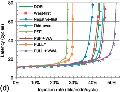
For bit reverse, a node with bit address {s3,s2,s1,s0} sends traffic to node {s0,s1,s2,s3}. Of this traffic, 62.5% is between the north-east and south-west quadrants; negative-first offers adaptiveness for this traffic. Further, 37.5% of the traffic is eastbound; west-first offers adaptiveness for this traffic, and performs worse than negative-first. Although WPF and aggressive VC reallocation improve the VC utilization for PSF + WA, PSF + WA is inferior to odd-even and negative-first. PSF + WA is limited by poor flexibility. FULLY + WA provides high VC utilization and routing flexibility, leading to the highest saturation throughput.3
Transpose-1 sends a message from node (i, j) to node (3 − j, 3 − i). Negative-first deteriorates to DOR for this pattern. West-first still offers adaptiveness for 37.5% of the traffic; thus, it is superior to negative-first. Odd-even offers greater adaptiveness than the other two partially adaptive algorithms and achieves higher performance. FULLY + WA offers adaptiveness for all traffic, performing 15.7% better than odd-even.
Transpose-2 is favorable to negative-first; node (i, j) communicates with node (j, i). Negative-first offers adaptiveness for all traffic and performs best. Although FULLY + WA offers adaptiveness for all traffic, it is limited by the restriction on EVCs: only if the port adheres to DOR can the EVC be used. The performance of FULLY + WA and odd-even with transpose-2 is similar to their performance with transpose-1 since the two patterns are symmetric and these designs offer the same adaptiveness for them.
With hotspot traffic, four nodes are chosen as hotspots and receive an extra 20% traffic in addition to uniform random traffic. This pattern mimics memory controllers receiving a disproportionate amount of traffic. FULLY + WA and odd-even are worse than negative-first and west-first. Owing to the limited adaptiveness offered by odd-even, it is inferior to FULLY+WA. DOR outperforms negative-first and west-first, since DOR more evenly distributes uniform traffic, which is the background in this pattern.
Table 6.3 gives average throughput gains of FULLY + WA over other designs. The 88.9% gap between FULLY+ WA and FULLY reflects the effect of novel flow control. The gap between FULLY + WA and PSF + WA represents the effect of routing flexibility; high flexibility brings a gain of 31.3%. The next section provides further insights into performance trends by analyzing the buffer utilization.
6.5.2 Buffer utilization of routing algorithms
This section provides further insights into the performance trends shown in Section 6.5.1 by analyzing the buffer utilization of all evaluated designs. Figure 6.11 illustrates the average buffer utilization of all network VCs at saturation for eight synthetic traffic patterns. The maximum and minimum rates are given by the error bars. Figure 6.11 also shows the saturation throughput supported by routing algorithms. There are several important insights.
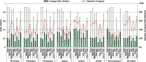
First, buffers are used to support high throughput. The saturation throughput of routing algorithms is related to the buffer utilization. Higher average buffer utilization generally leads to higher saturation throughput. This trend is obvious for bit complement. Bit complement sends traffic from node {s3,s2,s1,s0} to node {¬s3,¬s2,¬s1,¬s0}, which has the largest average hop count [31], and puts the highest pressure on the buffers among all evaluated traffic patterns.
Second, for the same routing algorithm in different traffic patterns, there may be fluctuations between the buffer utilization and the saturation throughput. For example, even though DOR shows much higher buffer utilization for bit complement than for shuffle, its saturation throughput for bit complement is lower than for shuffle. These fluctuations are because the same routing algorithm uses different VCs for different patterns; the network becomes saturated in different statuses. Similarly, since some algorithms use different VCs in the same traffic pattern, there may be slight fluctuations as well. For example, even though the average buffer utilization of west-first is slightly lower than that of DOR for bit reverse, its saturation throughput is higher than that of DOR.
Third, since all fully adaptive routing algorithms, including PSF, PSF + WA, FULLY, and FULLY + WA, use the same set of VCs for the same traffic pattern, their saturation throughput is roughly proportional to the buffer utilization. For instance, for bit reverse, PSF + WA's average buffer utilization is 78.3% higher than that of PSF, making it perform 79.5% better than PSF. Similarly, PSF + WA has 67.4% higher average buffer utilization than PSF in shuffle, and its saturation throughput is 67.2% higher than that of PSF.
Fourth, the network becomes saturated when some resources become saturated [8]. For most patterns and most algorithms, the bottleneck is VCs; networks become saturated when some VCs have more than 80% utilization, including DOR, west-first, negative-first, and odd-even in most patterns. When the algorithm provides abundant adaptiveness, it distributes traffic more uniformly among VCs, preventing them from becoming the bottleneck. Instead, the bottleneck may be the crossbar or network interface [50]. For example, since negative-first offers adaptiveness for all traffic in transpose-2, the network becomes saturated even when the maximum buffer utilization is only 49.2%. Similarly, at saturation, the maximum buffer utilization of PSF+WA and FULLY + WA is lower than that of partially adaptive routing and DOR.
Fifth, PSF and FULLY are limited by conservative VC reallocation; their maximum buffer utilization for the evaluated patterns is less than 40%. Applying WPF on AVCs and aggressive VC reallocation on EVCs greatly increases buffer utilization, which proportionally improves performance. FULLY supports higher routing flexibility than PSF, which brings higher buffer utilization and performance.
6.5.3 Sensitivity to network design
This section includes a sensitivity study for network configuration parameters. Except for the parameter analyzed, the other parameters are the same as for the baseline configuration. Table 6.4 lists the baseline parameter values and their variations. In this section we make a comparison with the performance of the baseline configuration shown Section 6.5.1.
Table 6.4
The Baseline Configuration and Variations
| Characteristic | Baseline | Variations |
| Topology (mesh) | 4 × 4 | 8 × 8 |
| VCs per VN | 2 | 4 |
| Flit buffers per VC | 4 | 3, 2 |
| SFP ratio | 80% | 60%, 40% |
6.5.3.1 SFP ratio
SFP ratios depend on the cache hierarchy, the coherence protocol, and the application. To test the robustness of our design, we evaluate SFP ratios of 60% and 40% for transpose-1. As shown in Figure 6.12, DOR, west-first, negative-first, and odd-even exhibit nearly identical performance for different SFP ratios. The aggressive VC reallocation makes their performance insensitive to the packet length distribution. However, the performance of PSF and FULLY improves as the SFP ratio shrinks. Their conservative VC reallocation favors long packets, which utilize buffers more efficiently than short ones. As the SFP ratio decreases, so does the possibility of applying WPF. Thus, the performance gap between FULLY + WA and FULLY (or PSF + WA and PSF) decreases. However, even with an SFP ratio of 40%, FULLY + WA achieves a 53.1% saturation throughput gain over FULLY.


6.5.3.2 VC depth
Different NoCs may use different VC depths. To test the flexibility, we evaluate three-flit-deep and two-flit-deep VCs with bit reverse traffic. In a comparison of four flits per VC (Figure 6.10a) and three flits per VC (Figure 6.13a), DOR and west-first perform similarly, while FULLY and PSF show minor performance degradation. DOR and west-first offer no or very limited adaptiveness, which is a major factor in their performance. Thus, reducing the VC depth from four to three has little effect. The bottleneck of FULLY and PSF is conservative VC reallocation. When we consider the majority of short packets, reducing the VC depth from four to three affects performance only slightly. However, the performance of FULLY + WA, PSF + WA, odd-even, and negative-first declines with shallower VCs since the VC depth is their bottleneck. Shallow VCs increase the number of hops that a blocked packet spans, which increases the effect of chained blocking [50].


When we compare three fits per VC and two flits per VC, the performance drops for all algorithms. FULLY outperforms DOR and west-first with two flits per VC. As the VC depth decreases, the difference between aggressive and conservative VC reallocation declines; FULLY exhibits a relative gain. Even with two flits per VC, WPF still optimizes the performance since short packets dominate the traffic. In Figure 6.13b, FULLY + WA performs 46.2% better than FULLY. Novel flow control leads to superior performance even with half of the buffers, which enables the design of a low-cost NoC. With two flits per VC (Figure 6.13b), FULLY + WA's saturation throughput is 40.3%, while FULLY's saturation throughput is 32.3% with four flits per VC (Figure 6.10a). The same is true for PSF + WA.
6.5.3.3 VC count
Semiconductor scaling and coherence protocol optimization may allow a VN to be configured with more VCs. When we compare four VCs per VN (Figure 6.14a) and two VCs per VN (Figure 6.10a), the performance of DOR, west-first, and odd-even is almost the same. These algorithms offer limited adaptiveness; although additional results show increasing the VC count from one to two improves performance, increasing the VC count from two to four cannot reduce the physical path congestion and does not further improve performance. Negative-first has a modest gain. In contrast, PSF, FULLY, PSF + WA, and FULLY + WA all have significant gains; more VCs mitigate the negative effects of conservative VC reallocation. The gap between PSF and FULLY (or PSF + WA and FULLY + WA) decreases with more VCs; more VCs reduce the possibility of using EVCs in PSF, which forces packets to lose adaptivity.

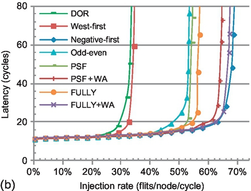
Figure 6.14b shows the performance of transpose-2, which is a favorable pattern for negative-first. FULLY + WA performs similarly to negative-first; with more VCs, the effect of restricting the use of EVCs in FULLY + WA declines. More VCs reduce the gap between FULLY and FULLY + WA (or PSF and PSF + WA), since the possibility of facing empty VCs increases. Furthermore, using WPF to forward entire packets into nonempty VCs may result in head-of-line blocking [8] and limit FULLY + WA (or PSF + WA). Nevertheless, FULLY + WA still shows an average 19.8% gain over FULLY for these two patterns with four VCs; providing high VC utilization outweighs the negative effect of head-of-line blocking in a VC-limited NoC. Similarly to VC depth, with only two VCs, FULLY + WA performs similarly or even better (Figure 6.10a and b) than FULLY with four VCs (Figure 6.14). WPF provides similar or higher performance with half as many VCs.
6.5.3.4 Network size
Figure 6.15 explores the scalability for an 8 × 8 mesh. The trends across different algorithms are similar to those for the 4 × 4 mesh (Figure 6.10). Communication is mostly determined by the traffic pattern. Since a larger network leads to higher average hop counts [31], it puts more pressure on VCs than a smaller one. Novel flow control achieves more gains in a larger network. The average improvement for these two patterns of FULLY + WA over FULLY is 108.2%, while it is 93.1% in a 4 × 4 mesh. As packets undergo more hops in a larger network, the possibility of entering an EVC increases. For PSF and PSF + WA, once the packet enters an EVC, it loses adaptivity in subsequent hops. Therefore, the gap between FULLY + WA and PSF + WA (or FULLY and PSF) increases with a larger network; providing routing flexibility becomes more important with a larger network.


6.6 Evaluation of parsec workloads
In this section we evaluate routing algorithms using PARSEC workloads.
6.6.1 Methodology and configuration
To measure full-system performance, we leverage FeS2 [39] for x86 simulation and BookSim for NoC simulation. FeS2 is implemented as a module for Simics [34]. We run PARSEC benchmarks [3] with 16 threads on a 16-core chip multiprocessor, which is organized as a 4 × 4 mesh. Prior research shows the frequency of simple cores in a many-core platform can be optimized to 5-10 GHz, while the frequency of an NoC router is limited by the allocator speed [11]. We assume cores are clocked five times faster than the network. Each core is connected to private, inclusive first-level and second-level caches. Cache lines are 64 bytes; long packets are five flits long with a 16-byte flit width. We use a distributed, directory-based MOESI coherence protocol which needs four VNs for protocol-level deadlock freedom. Each VN has two VCs; each VC is four flits deep. The router pipeline is the same as described in Section 6.4.4. All benchmarks use the simsmall input sets. The total run time is the performance metric. Table 6.5 gives the system configuration.
6.6.2 Performance
Figure 6.16 shows the speedups relative to PSF for PARSEC workloads. We divide the 10 applications into two classes. For blackscholes, fluidanimate, raytrace, and swaptions, different algorithms perform similarly. The working sets of these applications fit into the caches, and their computation phases consist of few synchronization points, leading to a lightly loaded network. The system performance of these applications is unaffected by techniques that improve the network throughput, such as sophisticated routing algorithms.
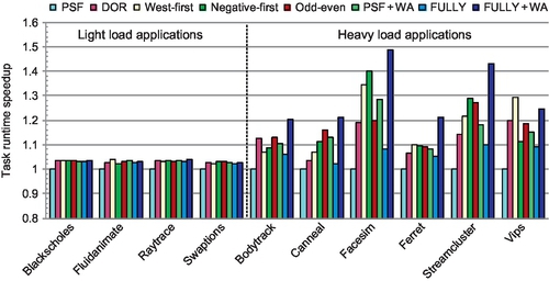
However, the routing algorithms affect the other six applications. These applications have heavier loads than the previous four applications. Yet, their average aggregate loads during the running periods are lower than the network saturation points. The highest average aggregate injection rate for canneal is 12.3% of flits per node per cycle, which is below the saturation points for all designs. Two factors bring performance improvements for these six applications. First, these applications exhibit period bursty communication and the synchronization primitives create one hotspot inside the network. The bursty communication and the hotspot make the network operate past saturation at times during the running period. Thus, these applications benefit from routing algorithms with higher throughputs. Second, short packets are critical in cache-coherent many-core platforms; they carry time-critical control messages that are often on the application's critical path. These short packets can affect the execution time significantly. The novel flow control reduces the packet latency, especially under heavy loads, which brings performance gains. For example, FULLY + WA has speedups of 48.5% and 43.0% over PSF for facesim and streamcluster.
Since most of the vips application's bursty communication is eastbound, west-first performs best for vips. For facesim and streamcluster, negative-first offers higher adaptiveness than odd-even, thus achieving better performance. For all heavy-load applications except vips, FULLY + WA performs best. Across these applications, FULLY + WA achieves an average speedup of 21.3% and a maximum speedup of 37.8% over FULLY. With sufficient flexibility, FULLY + WA has an average speedup of 12.1% over PSF + WA. The average speedups of FULLY + WA are 29.3%, 15.0%, 10.1%, 9.9%, and 10.4% over PSF, DOR, west-first, negative-first, and odd-even respectively.
6.7 Detailed analysis of flow control
In this section we perform a detailed analysis for the flow control mechanisms utilized in fully adaptive routing algorithms.
6.7.1 The detailed buffer utilization
6.7.1.1 Allowable EVCs
Here, we analyze aggressive VC reallocation and WPF by measuring the buffer utilization for network VCs. Since EVCs can be used only when the port adheres to DOR, not all EVCs are allowable for a particular traffic pattern. To clearly understand the system bottleneck, we leverage a recursive algorithm to calculate the allowable EVCs for all evaluated patterns. This algorithm is shown in Figure 6.17.
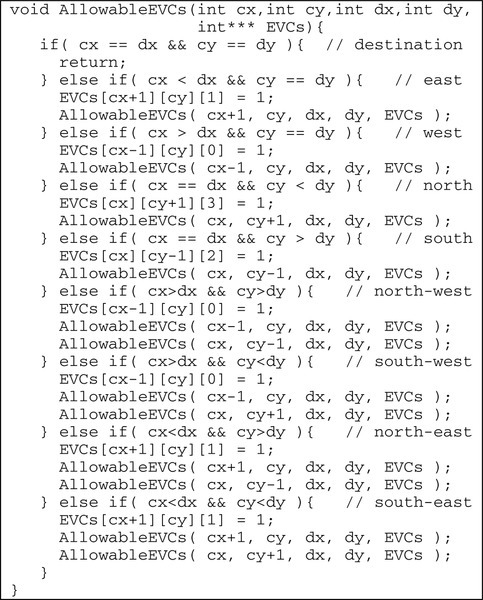
The algorithm recursively calculates all allowable EVCs for a packet sent from node (cx, cy) to node (dx, dy). At each step, the algorithm marks the EVC at the port which adheres to DOR as allowable by setting the corresponding element of the EVCs array to “1.” Fully adaptive routing may forward the packet to all neighbors inside the minimum quadrant defined by the current position and the destination. At the next step, the algorithm continues by using these neighbors as current positions. For example, if cx > dx and cy > dy, then the destination is in the north-west quadrant of the current position. The EVC at the east input port of node (cx − 1, cy) is allowed to be used. The packet may move to node (cx − 1, cy) and node (cx, cy − 1), and the algorithm continues by using them as current positions at the next step. By considering all source and destination pairs defined in the traffic pattern, we get the allowable EVCs in a 4 × 4 mesh network, As shown in Table 6.6, some traffic patterns, such as bit reverse, cannot use all EVCs, while other patterns, including bit complement and uniform random, can use all EVCs.
6.7.1.2 Performance analysis
Figure 6.18 gives the saturation throughput and buffer utilization for fully adaptive designs. PSF + WPF and FULLY + WPF apply WPF on both AVCs and EVCs. The difference between PSF + WA and PSF + WPF (or FULLY + WA and FULLY + WPF) is that PSF + WA (or FULLY + WA) applies aggressive VC reallocation on EVCs. The AVC utilization and EVC utilization are shown by the “average AVC utilization” and “average EVC utilization” bars. The “average allowable EVC utilization” bar gives the average utilization of allowable EVCs.

There are several insights from Figure 6.18. First, the performance gain of FULLY + WPF over FULLY (or PSF + WPF over PSF) is due to the improvement of buffer utilization for both AVCs and EVCs. The gain of FULLY + WA over FULLY + WPF (or PSF + WA over PSF + WPF) is due to the improvement of buffer utilization for EVCs; aggressive VC reallocation more efficiently utilizes EVCs than does WPF. For example, for bit reverse, the EVC utilization of FULLY + WA and FULLY + WPF is 0.377 and 0.247.
Second, the efficiency of aggressive VC reallocation depends on routing flexibility. FULLY can use AVCs after using EVCs; aggressive VC reallocation offers more gains for FULLY + WA than for PSF + WA. For bit reverse, FULLY + WA performs 26.6% better than FULLY + WPF; the 52.9% EVC utilization improvement of FULLY + WA over FULLY + WPF brings this gain. In contrast, PSF + WA achieves only 16.3% higher EVC utilization than PSF + WPF, which brings a 9.7% performance gain for PSF + WA.
Third, PSF + WPF requests an EVC only when the selected port adheres to DOR. Meanwhile, it always applies WPF on AVCs. These two factors induce higher pressure on AVCs than EVCs for PSF + WPF. For example, for transpose-1, the AVC utilization of PSF + WPF is 0.228, while the EVC utilization is 0.158 and the allowable EVC utilization is 0.210. FULLY can always request an EVC. Its allowable EVC utilization is higher than the AVC utilization for most patterns; FULLY puts more pressure on EVCs than on AVCs.
Fourth, the aggressive VC reallocation in FULLY + WA further increases the pressure on EVCs; the allowable EVC utilization of most patterns is more than 60% higher than the AVC utilization. FULLY + WA is limited by allowable EVCs, and mechanisms to improve the capacity of EVCs, such as dynamically sharing buffers between EVCs and AVCs, will be helpful to FULLY + WA.
6.7.2 The effect of flow control on fairness
As shown in Section 6.4.2, aggressive VC reallocation on EVCs can address the fairness issue of WPF on long packets. To illustrate this point, Figures 6.19 and 6.20 show the latency distribution of short and long packets for FULLY + WPF and FULLY + WA with bit complement traffic; the overall network average latencies are both 52 cycles. Other patterns have similar trends. The short packet latency of FULLY + WPF has three distinct peaks at 11, 17, and 23 cycles, corresponding to packets which take three, five, and seven hops respectively without any queuing delay. Since each flit of a long packet may face different switch allocation congestion, the long packet latency only exhibits one peak at 27 cycles, corresponding to packets with seven hops.


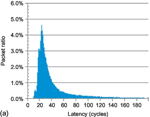

The short and long packet latencies of FULLY + WA both have one peak, at 23 and 27 cycles respectively. To illustrate the difference between FULLY + WA and FULLY + WPF, we subtract the data in Figure 6.19 from the data in Figure 6.20, as shown in Figure 6.21. The ratio of short packets with a latency between nine and 23 cycles for FULLY + WA is 13.2% less than that for FULLY + WPF. On the other hand, FULLY + WA has 8.8% more long packets with a latency between 19 and 42 cycles than FULLY + WPF. Compared with FULLY + WPF, FULLY + WA accelerates long packets, while sacrificing short packets.


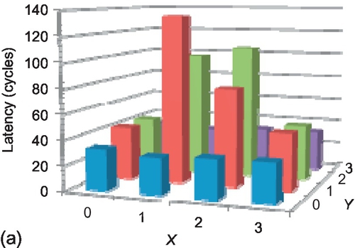
The effect on fairness can also be observed from the average latency of packets injected from different sources, as shown in Figure 6.22. In FULLY + WPF, middle nodes have very high latency as their injected long packets are always inferior to short packets from edge nodes. FULLY + WA reduces the peak latency for these middle nodes from 134 cycles to 104 cycles, and increases the latency for the edge nodes, achieving more even latency distribution throughout the network.

The latencies shown in Figures 6.19–6.22 are snapshots when the network average latencies are 52 cycles. With decreasing injection rate, the latency differences between FULLY + WA and FULLY + WPF become insignificant as the network contention becomes less likely. Conversely, the differences become more pronounced as the network approaches saturation. For example, when the average network latencies of FULLY + WPF and FULLY + WA are both 75 cycles, FULLY + WA has 10.3% more long packets with a latency between 21 and 48 cycles than FULLY + WPF, while FULLY + WPF has 15.7% more short packets with a latency between 11 and 25 cycles than FULLY + WA.
6.8 Further discussion
6.8.1 Packet length
Packet lengths for cache coherence traffic typically have a bimodal distribution. However, optimizations such as cache line compression [11, 25] create packet distributions that are not bimodal; the packet length may be distributed between a single flit and the maximum number of flits per packet supported by the architecture. To apply WPF on such NoCs, more downstream VC status registers are needed for the first-stage arbiters shown in Figure 6.9. An important consideration is how many different packet lengths to apply WPF to. The longest packet length that can use WPF is one flit shorter than the VC depth. Designers can ignore long packets, since there are few opportunities to apply WPF on long packets. This tradeoff depends on the packet length distribution, VC depth, hardware overhead, and expected performance gain.
6.8.2 Dynamically allocated multiqueue and hybrid flow controls
Previous research proposed dynamically allocated multiqueue (DAMQ) designs for both off-chip networks [49] and on-chip networks [40, 55] to improve VC utilization. Even with DAMQ, allowing multiple packets to reside in one VC may lead to deadlock similar to that in Figure 6.3 for fully adaptive routing in wormhole networks. WPF is complementary to DAMQ as it ensures deadlock freedom. WPF can be viewed as a hybrid mechanism combining wormhole flow control and VCT flow control. There are some hybrid flow controls [30, 45, 47]. Hybrid switching [45] and buffered wormhole [47] remove a blocked packet to release held physical channels by using either the processing node memory [45] or a central buffer [47]. Layered switching divides a long packet into several groups and tries to keep switch allocation grants for a whole group [30]. Our research is different; we focus on improving the performance while avoiding deadlock.
6.9 Chapter summary
An abundance of short packets and a limited VC budget increase the importance of flow control in the performance of cache-coherent NoCs. We proposed two novel flow control designs for fully adaptive routing in wormhole networks. WPF is an important extension to several deadlock avoidance theories. It reallocates a nonempty VC if the VC has enough buffers for an entire packet. Then, we extended Duato's theory to apply aggressive VC reallocation on EVCs. On the basis of the proposed flow control, we designed a low-cost routing algorithm to maintain maximal routing flexibility. Compared with existing fully adaptive routing, our design performs similarly or even better with half of the buffers or VCs, enabling the design of a low-cost NoC. Our design also outperforms several partially adaptive and deterministic routing algorithms.
Appendix: logical equivalence of Alg and Alg + WPF
In Section 6.4.1 we proposed Theorem 6.1, which declares that if a fully adaptive routing algorithm with conservative VC reallocation (named Alg) is deadlock-free, then applying WPF on this routing algorithm (named Alg + WPF) is also deadlock-free. In this section we prove that if Alg + WPF is deadlock-free, then Alg is deadlock-free as well. In addition to Assumption 6.1 in Section 6.4.1, this proof needs another simple assumption about the routing algorithm.
Assumption 6.2 implies that if two packets are injected from the same source and destined for the same node, they can use the same set of VCs even though these packets have different lengths. This assumption was generally used in many previous theories [4, 6, 12, 13, 17–19, 29, 44, 48, 52, 53]. We prove the following theorem.
Theorem 6.4
If Alg + WPF is deadlock-free, then Alg is also deadlock-free.
Informal description: This proof is similar to the proof of Theorem 6.1. We prove that if Alg has a deadlock configuration, then Alg + WPF has a deadlock configuration as well. We use Config0 in Figure 6-A.1 as an example. We replace packet Pi with packet P′i to completely fill all VCs. The source and destination of P′i are the same as those of Pi, while P′i may have more flits than Pi to completely fill the VCs. We prove that Alg + WPF can achieve Config0, and that Config0 is a deadlock configuration. However, Alg + WPF is deadlock-free; thus, there is no such configuration.
Proof: By contradiction. If Alg is not deadlock-free, then there is a deadlock configuration (Config0) in which a set of packets, ![]() , is waiting for VCs held by other packets in
, is waiting for VCs held by other packets in ![]() . We prove that there is a deadlock configuration for Alg + WPF in three steps.
. We prove that there is a deadlock configuration for Alg + WPF in three steps.
Step 1: We build a new configuration based on Config0. Consider each packet Pi in ![]() . If Pi does not completely fill all VCs where its flits reside, we replace Pi with packet P′i to completely fill all VCs occupied by Pi. The source and destination of P′i are the same as those of Pi, and the length of P′i is larger than that of Pi. If Pi completely fills all VCs where its flits reside, P′i is the same as Pi. We label the new configuration as Config1, and the set of packets in Config1 as
. If Pi does not completely fill all VCs where its flits reside, we replace Pi with packet P′i to completely fill all VCs occupied by Pi. The source and destination of P′i are the same as those of Pi, and the length of P′i is larger than that of Pi. If Pi completely fills all VCs where its flits reside, P′i is the same as Pi. We label the new configuration as Config1, and the set of packets in Config1 as ![]() .
.
Step 2: We prove that when the network is routed by Alg + WPF, all packets in ![]() can move to their current VCs in Config1, and the head flits of these packets are at VC heads. For each packet P′i in
can move to their current VCs in Config1, and the head flits of these packets are at VC heads. For each packet P′i in ![]() , we consider its corresponding packet Pi in Config0. We further consider each hop hopk of Pi when it is routed by Alg. Assume the head flit of Pi moves to VCk's head during hopk. The routing algorithm allows Pi to use VCk. Although P′i and Pi may have different packet lengths, they have the same source and destination information. On the basis of Assumption 6.2, the routing algorithm allows P′i to use VCk as well.
, we consider its corresponding packet Pi in Config0. We further consider each hop hopk of Pi when it is routed by Alg. Assume the head flit of Pi moves to VCk's head during hopk. The routing algorithm allows Pi to use VCk. Although P′i and Pi may have different packet lengths, they have the same source and destination information. On the basis of Assumption 6.2, the routing algorithm allows P′i to use VCk as well.
Since Alg + WPF is deadlock-free, VCk must become available at some time. On the basis of Assumption 6.1, P′i has some possibility to request VCk. There are two cases when P′i requests VCk:
(1) VCk is empty. VCk can be reallocated to P′i with conservative VC reallocation. Thus, the head flit of P′i will move to VCk's head.
(2) VCk is not empty. But VCk has already received the tail flit of the last allocated packet and still has enough buffers for P′i. WPF can reallocate VCk to P′i. Yet, when P′i reaches VCk, its head flit is not at VCk's head. Considering Alg + WPF is deadlock-free, the packets in VCk before P′i must be sent out in limited time. Then, the head flit of P′i is at VCk's head.
When we consider cases i and 2 together, if the head flit of Pi moves to the head of a VC during any hop when it is routed by Alg, the head flit of P′i can also move to the same VC head when it is routed by Alg + WPF. Thus, when it is routed by Alg + WPF, P′i can be routed to its current VC(s) in Config1, and the head flit of P′i is at the VC head.
Step 3: We prove that Config1 is a deadlock configuration for Alg + WPF. Since all VCs in Config1 are completely filled, all packets in ![]() are still waiting for VCs held by other packets in
are still waiting for VCs held by other packets in ![]() , even with WPF applied. Config1 is a deadlock configuration for Alg + WPF. But Alg + WPF is deadlock-free, so there is no deadlock configuration. Thus, Alg is deadlock-free as well.
, even with WPF applied. Config1 is a deadlock configuration for Alg + WPF. But Alg + WPF is deadlock-free, so there is no deadlock configuration. Thus, Alg is deadlock-free as well.
Theorem 6.1 declares that if Alg is deadlock-free, then Alg + WPF is deadlock-free as well. Theorem 6.4 declares that if Alg + WPF is deadlock-free, then Alg is deadlock-free as well. If we consider these two theorems together, the deadlock freedom of Alg + WPF is logically equivalent to the deadlock freedom of Alg. Therefore, the WPF optimization of traditional wormhole flow control does not have any influence on the deadlock freedom.