Deadlock-free flow control for torus networks-on-chip†
Abstract
Short and long packets coexist in cache-coherent networks-on-chip. Existing designs for torus networks do not efficiently handle variable-size packets. For deadlock-free operations, a design uses two virtual channels (VCs), which negatively affects the router frequency. Some optimizations use one VC. Yet, they regard all packets as maximum-length packets, inefficiently utilizing the precious buffers. We propose flit bubble flow control (FBFC), which maintains one free flit-size buffer slot to avoid deadlock. FBFC uses one VC, and does not treat short packets as long ones. It achieves both high frequency and efficient buffer utilization. FBFC performs 92.8% and 34.2% better than the localized bubble scheme (LBS) and the critical bubble scheme (CBS) for synthetic traffic in a 4 × 4 torus. The gains increase in larger networks; they are 107.2% and 40.1% in an 8 × 8 torus. FBFC achieves an average speedup of 13.0% over LBS for PARSEC workloads. Our results also show that FBFC is more power efficient than LBS and CBS, and a torus with FBFC is more power efficient than a mesh.
7.1 Introduction
Optimizing networks-on-chip (NoCs) [18] on the basis of coherence traffic is necessary to improve the efficiency of many-core coherence protocols [41]. The torus is a good NoC topology candidate [53, 54]. The wraparound links convert plentiful on-chip wires into bandwidth [18], and reduce hop counts and latencies [53]. Its node symmetry helps to balance network utilization [53, 54]. Several products [21, 28, 31] use a ring or 1D torus NoC. Also, the 2D or higher-dimensional torus is widely used in off-chip networks [4, 20, 44, 51].
Despite the many desirable properties of a torus, additional effort is needed to handle deadlock owing to cyclic dependencies introduced by wraparound links. A deadlock avoidance scheme should support high performance with low overhead. Requiring minimum virtual channels (VCs) [16] is preferable, because more VCs not only increase the router complexity, but also limit the frequency. Buffers are a precious resource [24, 46]; an efficient design should maximize performance with limited buffers. There is a gap between existing proposals and these requirements.
A conventional design [19] uses two VCs to remove cyclic dependencies; this introduces large allocators and negatively affects the router frequency. Optimizations [10, 13] for virtual cut-through (VCT) networks [32] avoid deadlock by preventing the use of the last free packet-size buffer inside rings; only one VC is needed. However, with variable-size packets, each packet must be regarded as a maximum-length packet [4]. This restriction prevents deadlock, but results in poor buffer utilization and performance, especially for short-packet-dominating coherence traffic.
In addition to the majority short packets, cache-coherent NoCs also deliver long packets. Even though multiple virtual networks (VNs) [19] may be configured to avoid protocol-level deadlock, these two types of packets still coexist in a single VN. For example, short read requests and long write-back requests are sent in VN0 of AlphaServer GS320, while long read responses and short write-back acknowledgments (ACKs) are sent in VN1; both VNs carry variable-size packets [25]. Similarly, all VNs in DASH [36], Origin 2000 [35], and Piranha [6] deliver variable-size packets.
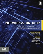
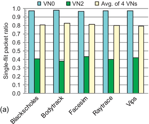
With a typical 128-bit NoC flit width [24, 38, 46], the majority control packets have one flit; the remaining data packets contain a 64-byte cache line and have five flits. Figure 7.1 shows the packet length distribution of some representative PARSEC workloads [8] with two coherence protocols.1 Both protocols use four VNs. For each protocol, two VNs carry variable-size packets, and the other two have only short packets. The single-flit packet (SFP) ratios of VN0 in the MOESI directory [45], and VN2 and VN3 in the AMD's Hammer [15] are all higher than 90%. With such high SFP ratios, regarding all packets as maximum-length packets strongly limits buffer utilization. As shown in Section 7.6.2, the buffer utilization of existing designs at saturation is less than 40%. This brings large performance loss. It is imperative to improve deadlock avoidance schemes for torus NoCs.
To address the limitations of existing designs, we propose a novel deadlock avoidance theory, flit bubble flow control (FBFC), for torus cache-coherent NoCs. FBFC leverages wormhole flow control [20]. It avoids deadlock by maintaining one free flit-size buffer slot inside a ring. Only one VC is needed, reducing the allocator size and improving the frequency. Furthermore, short packets are not regarded as long packets in FBFC, leading to high buffer utilization. On the basis of this theory, we provide two implementations: FBFC-localized (FBFC-L) and FBFC-critical (FBFC-C).
Experimental results show that FBFC outperforms dateline [19], the localized bubble scheme (LBS) [10], and the critical bubble scheme (CBS) [13]. FBFC achieves an approximately 30% higher router frequency than dateline. For synthetic traffic, FBFC performs 92.8% and 34.2% better than LBS and CBS in a 4 × 4 torus. FBFC's advantage is more significant in larger networks; these gains are 107.2% and 40.1% in an 8 × 8 torus. FBFC achieves an average speedup of 13.0% and a maximal speedup of 22.7% over LBS for PARSEC workloads. FBFC's gains increase with fewer buffers. The power-delay product (PDP) results show that FBFC is more power efficient than LBS and CBS, and a torus with FBFC is more power efficient than a mesh. In this chapter we make the following contributions:
• We analyze the limitations of existing torus deadlock avoidance schemes, and show that they perform poorly in cache-coherent NoCs.
• We demonstrate that in wormhole torus networks, maintaining one free flit-size buffer slot can avoid deadlock, and propose the FBFC theory.
• We present two implementations of FBFC; both show substantial performance and power efficiency gains over previous proposals.
7.2 Limitations of existing designs
Here, we analyze existing designs. Avoiding deadlock inside a ring combined with dimensional order routing (DOR) is the general way to avoid deadlock in tori. We use the ring for discussion.
7.2.1 Dateline
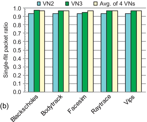
As shown in Figure 7.2, dateline [19] avoids deadlock by leveraging two VCs: VC0i and VC1i. It forces packets to use VC1i after crossing the dateline to form acyclic channel dependency graphs [17, 19]. Dateline can be used in both packet-based VCT and flit-based wormhole networks. It uses two VCs, which results in larger allocators and lower router frequency.
7.2.2 Localized bubble scheme
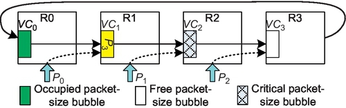
Bubble flow control [10, 50] is a deadlock avoidance theory for VCT torus networks. It forbids the use of the last free packet-size amount of buffers (a packet-size bubble); only one VC is needed. Theoretically, any free packet-size bubble in a ring can avoid deadlock [10, 50]. However, owing to difficulties in gathering global information and coordinating resource allocation for all nodes, previous designs applied a localized scheme; a packet may be injected only when the receiving VC has two free packet-size bubbles [10, 50]. Figure 7.3 gives an example. Here, three packets, P0, P1, and P2, are waiting. Theoretically, they can all be injected. Yet, with a localized scheme, only P0 can be injected since only VC1 has two free packet-size bubbles. LBS requires each VC to be deep enough for two maximum-length packets.

7.2.3 Critical bubble scheme
CBS [13] marks at least one packet-size bubble in a ring as critical. A packet can be injected only if its injection will not occupy a critical bubble. Control signals between routers track the movement of critical bubbles. CBS reduces the minimum buffer requirement to one packet-size bubble. In the example in Figure 7.4, the bubble at VC2 is marked as critical; P2 can be injected. P1 cannot be injected since its injection would result in it occupying the critical bubble. Requiring that critical bubbles can be occupied only by packets in a ring guarantees that there is at least one free bubble to avoid deadlock. When P3 advances into VC2, the critical bubble moves into VC1. Now, VC1 maintains one free bubble.
7.2.4 Inefficiency with variable-size packets
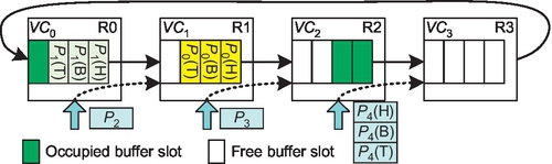
LBS and CBS are proposed for VCT networks; they are efficient for constant-size packets. Yet, as observed by the Blue Gene/L team, LBS deadlocks with variable-size packets owing to bubble fragmentation [4]. Figure 7.5 shows an example with SFPs and two-flit packets. A free full-size (two-slot) bubble exists in VC2 at cycle 0. When P0 moves into VC2, the bubble is fragmented across VC1 and VC2. VCT reallocates a VC only if it has enough space for an entire packet. Since VC2's free buffer size is less than P1's length, P1 cannot advance, and deadlock results. CBS has a similar problem. To handle this issue, Blue Gene/L regards each packet as a maximum-length packet [4]. Now, there is no bubble fragmentation. However, this reduces buffer utilization, especially in coherence traffic, for which short packets are in the majority.

7.3 Flit bubble flow control
We first propose the FBFC theory. Then, we give two implementations. Finally, we discuss starvation.
7.3.1 Theoretical description
We notice that maintaining one free flit-size buffer slot can avoid deadlock in wormhole networks. This insight leverages a property of wormhole flow control: advancing a packet with wormhole flow control does not require the downstream VC to have enough space for the entire packet [20]. To show this, in Figure 7.6, a free buffer slot exists in VC2 at cycle 0; P0 advances at cycle 1. A free slot is created in VC1 owing to P0's movement. Similarly, P3's head flit moves to VC1 at cycle 2, creating a free slot in VC0. This free buffer slot cycles inside the ring, allowing all flits to move.

The packet movement in a ring does not reduce free buffer amounts since forwarding one flit leaves its previously occupied slot free; only injection reduces free buffer amounts. The theory is declared as follows.
Since one free buffer slot (flit bubble)2 avoids deadlock, we call this theory flit bubble flow control (FBFC). DOR removes the cyclic dependency across dimensions; combining DOR with FBFC avoids deadlock in tori. FBFC has no bubble fragmentation; its bubble is flit-size. Thus, FBFC does not regard each packet as a maximum-length packet. Only one VC is needed; this improves the frequency. FBFC uses wormhole flow control to move packets inside a ring. It requires the injection procedure to leave one slot empty. Later, we show two schemes to satisfy this requirement.
7.3.2 FBFC-localized
The key point in implementing FBFC is to maintain a free buffer slot inside each ring. We first give a localized scheme: FBFC-L. When combined with DOR, a dimension-changing packet is treated the same as an injecting packet. The rules of FBFC-L are as follows:
(1) Forwarding of a packet within a dimension is allowed if the receiving VC has one free buffer slot. This is the same as wormhole flow control.
(2) Injecting a packet (or changing its dimension) is allowed only if the receiving VC has one more free buffer slot than the packet length. This requirement ensures that after injection, one free buffer slot is left in the receiving VC to avoid deadlock.
Figure 7.7 shows an example. Three packets are waiting. There are two and four free slots in VC2 and VC3 respectively; these are one more than the lengths of P3 and P4 respectively. P3 and P4 can be injected. After injection, at least two free slots are left in the ring. P2 cannot be injected since VC1 has only one free slot, which is equal to P2's length. However, according to wormhole flow control, the free slot in VC1 allows P1's head flit to advance. In FBFC-L, each VC must have one more buffer slot than the size of the longest packet.
7.3.3 FBFC-critical
To reduce the minimum buffer requirement, we propose a critical design: FBFC-C. FBFC-C marks at least one free buffer slot as a critical slot, and restricts this slot to be occupied only by packets traveling inside the ring. The rules of FBFC-C are as follows:
(1) Forwarding of a packet within a dimension is allowed if the receiving VC has one free buffer slot, no matter if it is a normal or a critical slot.
(2) Injecting a packet is allowed only if the receiving VC has enough free normal buffer slots for the entire packet. After injection, the critical slot must not be occupied. This requirement maintains one free buffer slot.
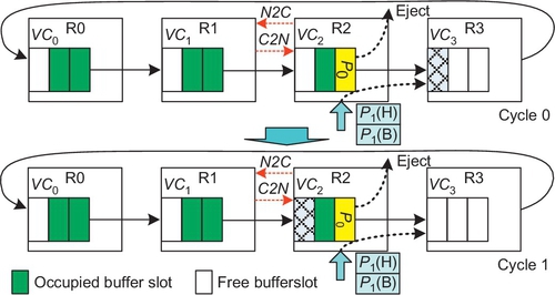
Figure 7.8 shows an example. At cycle 0, one critical buffer slot is in VC1. VC2 and VC3 have enough free normal slots to hold P3 and P4 respectively; P3 and P4 can be injected. They do not occupy the critical slot, indicating the existence of a free slot (the critical slot) elsewhere in the ring. Since the only free slot in VC1 is a critical one, P2 cannot be injected. Yet, this critical slot allows P1's head flit to move. At cycle 1, P1's head flit advances into VC1, moving the critical slot backward into VC0. This is done by R0 asserting a signal to indicate to R3 that it should mark the newly freed slot in VC0 as a critical one. More details are provided in Section 7.4. The minimum buffer requirement of FBFC-C is the same as that of CBS; a VC can hold the largest packet. This is one slot less than FBFC-L.

The injection in FBFC-L and FBFC-C is similar to that in VCT; they require enough buffers for packets before injection. After injection, a minimum of one slot is left free for wormhole flow control. They can be regarded as applying VCT for injection (or dimension-changing) in wormhole networks. These hybrid schemes are straightforward ways to address the limitations of existing designs.
7.3.4 Starvation
FBFC-L and FBFC-C must deal with starvation. The starvation in FBFC-L is intrinsically the same as in LBS [10]: Injected packets need more buffers than inside-ring traveling packets. Figure 7.9 shows a starvation example for FBFC-L. Here, if node R0 continually injects packets, such as P0, destined for R3, then P1 cannot be injected. We design a starvation prevention mechanism; if a node detects starvation, it will notify all other nodes in a ring to stop injecting packets. A sideband network conveys the control signal (starve). Once blocked cycles of P1 exceed a threshold value, R1 asserts the “starve” signal. R0 stops injecting packets after receiving “starve” and forwards it to R3. All nodes except R1 stop injecting packets. Finally, P1 can be injected. Then, R1 deasserts “starve” to resume injection by other nodes. To handle the corner case of multiple nodes simultaneously detecting starvation, “starve” carries an “ID” field to differentiate the nodes of a ring. Since the sideband network is unblocking, a router can identify the sending time slot of “starve” on the basis of the “ID” field. The “ID” field and the sending time slot order “starve” signals. If the incoming “starve” has a higher order than the currently serving “starve,” the router forwards the incoming signal to its neighbor.

FBFC-C has another starvation scenario in addition to the previous one; it is due to the critical bubble stall. CBS has a similar issue (L. Chen and T. Pinkston, personal communication, 2012 [11]). Figure 7.10 shows that the critical bubble is in VC3 at cycle 0. The bubble movement depends on the packet advancement. If all packets in VC2, such as P0, are destined for R2, they will be ejected. Since no packet moves to VC3, the critical bubble stalls at VC3. P1 cannot be injected. This can be prevented by proactively transferring the critical bubble backward if the upstream VC has a free normal bubble. As shown in Figure 7.10, a pair of “N2C” (NormalToCritical) and “C2N” (CriticalToNormal) signals are used. If R2 detects that the critical bubble stall prohibits P1's injection, it asserts “N2C” to R1. If VC2 has a free normal bubble, R1 will change it into a critical one in cycle 1. “C2N” notifies R2 that the critical bubble in VC3 can now be changed into a normal one. P1 can be injected. Note that the bubble status is maintained at upstream routers.
7.4 Router microarchitecture
In this section, we discuss wormhole routers for FBFC. We also discuss VCT routers for LBS and CBS.
7.4.1 FBFC routers
The left side of Figure 7.11 shows a canonical wormhole router, which is composed of the input units, routing computation (RC) logic, VC allocator (VA), switch allocator (SA), crossbar, and output units [19, 23]. Its pipeline includes RC, VA, SA, and switch traversal [19, 23]. The output unit tracks downstream VC status. The “input_vc” register records the allocated input VC of a downstream VC. The 1-bit “idle” register indicates whether the downstream VC receives the tail flit of the last packet. “Credits” records credit amounts. Lookahead routing [19] performs RC in parallel with VC allocation. To be fair with VCT routers, wormhole routers try to hold SA grants for entire packets; they prioritize VCs that received switch access previously [34].
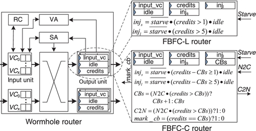
FBFC mainly modifies output units. As shown at the top right in Figure 7.11, two 1-bit registers, “injs” and “injl”, are needed for the bimodal length coherence traffic. They record whether a downstream VC is available for injecting (or dimension-changing) short and long packets. When packets are to be injected (or change dimensions), VA checks the appropriate register according to packet lengths. SFPs require at least two credits in a downstream VC. A five-flit packet needs at least six credits. If the incoming “starve” signal is asserted to prevent starvation for some other router, both registers are reset to forbid injection. Figure 7.11 shows the logic. This logic can be precalculated and is off the critical path.
The output unit of an FBFC-C router is shown at the bottom right in Figure 7.11. Another register, “CBs”, records critical flit bubble counts. The logic of “injs” and “injl” is modified; packet injection is allowed only if the downstream VC has enough free normal slots. Specifically, “credits – CBs” is not less than the packet length. FBFC-C routers proactively transfer critical slots to prevent starvation. When there is an incoming “N2C” signal, the output unit checks whether there are free normal slots. If there are, “CBs” is increased by 1, and “C2N” is asserted to inform the neighboring router to change its critical slot into a normal one. The “mark_cb” signal is asserted when a flit will occupy a downstream critical slot; it informs the upstream router to mark the newly freed slot as critical. Similarly, this logic is off the critical path.
7.4.2 VCT routers
We discuss VCT routers for LBS and CBS. A typical VCT router [19, 22] is similar to the wormhole one shown in Figure 7.11. The main difference is VC allocation: VCT reallocates a VC only if it guarantees enough space for an entire packet. The advance of a packet returns one credit, which represents the release of a packet-size amount of buffers. We apply some optimizations to favor LBS and CBS. The SA grant holds for an entire packet. Since VA guarantees enough space for an entire packet, once a head flit moves out, that packet's remaining flits can advance without interruption; all of the packet's occupied buffers will be freed in limited time. Thus, a credit is returned once a head flit moves out. The lookahead credit return allows the next packet to use this VC even if there is only one free slot, overlapping the transmission of an incoming packet and an outgoing packet. This optimization brings an injection benefit for CBS, which we discuss in Section 7.7.2. The LBS router's output unit is similar to that of the FBFC-L router. The difference is that the LBS router needs only one “inj” register since all packets are regarded as long packets. The “credits” register records free buffer slots in the unit of packets instead of flits. The CBS router's output unit also has these differences. Since CBS starves only because of the critical bubble stall, there is no incoming “starve” signal.
7.5 Methodology
We modify BookSim [29] to implement FBFC-L and FBFC-C and to compare them with dateline, LBS, and CBS. We use both synthetic traffic and real applications. Synthetic traffic uses one VN since each VN is independent. The traffic has randomly injected SFPs and five-flit packets. The baseline SFP ratio is 80%, which is similar to the overall SFP ratio of a MOSEI directory protocol. The warm-up and measurement periods are 10,000 and 100,000 cycles.
Although FBFC works for high-dimensional tori, we focus on 1D and 2D tori as they best match the physical layouts. The routing is DOR; with equal positive and negative distances, the positive direction is used. Buffers are precious in NoCs; most evaluation uses 10 slots at each port per VN. Bubble designs have one VC per VN. Dateline divides 10 slots into 2 VCs; 5 slots per VC cover credit round-trip delays [19]. Instead of injecting packets into VC0i first (Figure 7.2), then switching to VC1i after the dateline [19], we apply a balancing optimization to favor dateline; injected packets choose VCs according to whether they will cross dateline [51]. Packets use VC1is if they will cross dateline. Otherwise, they use VC0is. CBS and FBFC-C set one critical bubble for each ring; CBS marks five slots as a packet-size critical bubble, and FBFC-C marks one slot as a flit-size critical bubble. The starvation threshold values (STVs) in FBFC-L and LBS are 30 cycles. The STVs due to critical bubble stall in CBS and FBFC-C are three cycles. We explore this issue in Section 7.7.5.
VA and SA delays determine router frequencies [7, 48]. Dateline uses two VCs per VN, resulting in large allocators and long critical paths. A technology-independent model [48] is used to calculate the delays, as shown in Table 7.1. Separable input-first allocators [19] with matrix arbiters [19] are used. VC allocation is independent for each VN [7], making switch allocation the critical path with multiple VNs. Dateline's SA delay with four VNs is approximately 30% higher than that of bubble designs. Similarly, with a 45-nm low-power technology, the SA delay with eight VCs is about 15-26% higher than the delay with four VCs for several allocator types [7].
Table 7.1
The Delay Results, Expressed as Fan-out of 4
| No. of VN | Ring (3 ports) | Torus (5 ports) | ||||
| Bubble | Dateline | Increase (%) | Bubble | Dateline | Increase (%) | |
| VA | 8.4 | 12.2 | 45 | 10.0 | 13.8 | 38 |
| 1 SA | 6.9 | 11.7 | 69 | 8.5 | 13.3 | 57 |
| 2 SA | 11.7 | 16.5 | 41 | 13.3 | 18.1 | 36 |
| 3 SA | 14.5 | 19.3 | 33 | 16.1 | 20.9 | 30 |
| 4 SA | 16.5 | 21.3 | 29 | 18.1 | 22.9 | 27 |
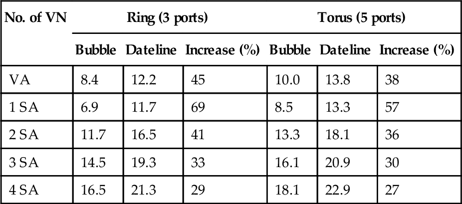
One VC per VN for bubble, and two VCs per VN for dateline.
To measure full-system performance, we leverage FeS2 [45] for x86 simulation and BookSim for NoC simulation. FeS2 is a module for Simics [40]. We run PARSEC workloads [8] with 16 threads on a 16-core chip multiprocessor (CMP). Since dateline's frequency can be different with bubble designs, we do not evaluate dateline for real workloads. The frequency of a simple CMP core can be 2-4 GHz, while the frequency of NoC is limited by allocator speeds [27, 42]. We assume cores run two times faster than the NoC. Each core is connected to private, inclusive first-level (L1) and second-level (L2) caches. Cache lines are 64 bytes; long packets are five flits with a 16-byte flit width. We use a MOESI directory protocol to maintain the coherence among L2 caches; it uses four VNs to avoid protocol-level deadlock. Each VN has 10 slots. Workloads use simsmall input sets. The task run time is the performance metric. Table 7.2 gives the configuration.
7.6 Evaluation on 1D tori (rings)
7.6.1 Performance
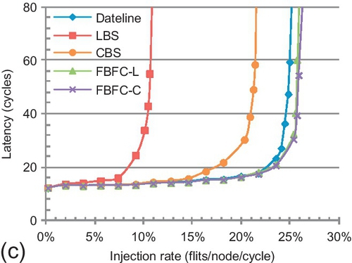
Our evaluation for synthetic patterns [19] starts with an eight-node ring. As shown in Figure 7.12, FBFC-L is similar to FBFC-C; although FBFC-C needs one less slot for injection, this benefit is minor since 10 slots are used. FBFC obviously outperforms LBS and CBS. Across all patterns, the average saturation throughput3 gains of FBFC-C over LBS and CBS are 73.5% and 33.9%. LBS and CBS are limited by regarding short packets as long ones. The advance of a short packet in FBFC-C uses one slot, while it uses five slots in LBS and CBS. LBS is also limited by its high injection buffer requirement; CBS shows an average gain of 29.6% over LBS.


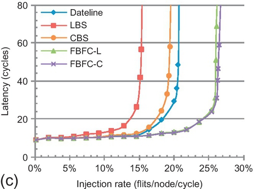

In Figure 7.12, dateline is superior to LBS and CBS. The results are reported in cycles and flits per node per cycle. These metrics do not consider router frequencies. According to Table 7.1, if all routers are optimized to maximum frequencies, dateline is approximately 30% slower than bubble designs. To make a fair comparison, we leverage frequency-independent metrics. The unit seconds is used for latency comparison. Owing to its lower frequency, dateline's cycle in seconds is 30% longer than the bubble design's cycle in seconds. Thus, dateline's zero-load latency in seconds is 30% higher. Flits per node per second is used for throughput comparison. Since dateline's cycle in seconds is longer than the bubble design's cycle in seconds, dateline's throughput in flits per node per second drops. For example, its throughput in flits per node per second for uniform random traffic is 7.5% lower than that of CBS.
Dateline divides buffers into two VCs. Shallow VCs make packets span more nodes, which increases the chained blocking effect [56]; this brings a packet forwarding limitation for dateline. Yet, dateline is superior to FBFC for injection and dimension-changing: long packets can be injected or change dimensions with one free slot. We introduce a metric: injection/dimension-changing (IDC) count. The IDC count of a packet includes the number of times a packet is injected plus the number of times it changes dimensions.
The trends between dateline and FBFC depend on hop counts and IDC counts of the traffic. FBFC-C outperforms dateline for all patterns. A ring has no dimension changing; all patterns' IDC counts are no more than one, hiding dateline's merit. The largest gains are 29.2% and 18.8% for transpose and tornado. Transpose's IDC and hop counts are 0.75 and 2.25. Tornado's IDC and hop counts are one and four. They reveal dateline's limitation on packet forwarding.
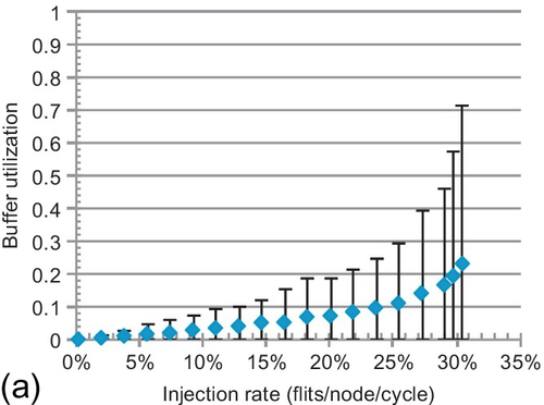
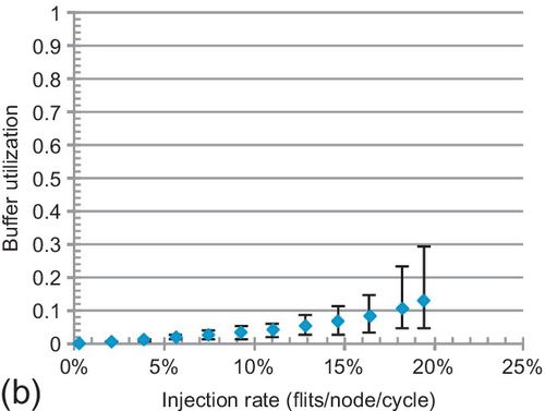
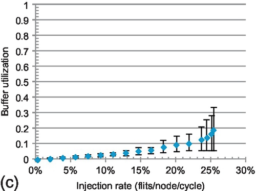
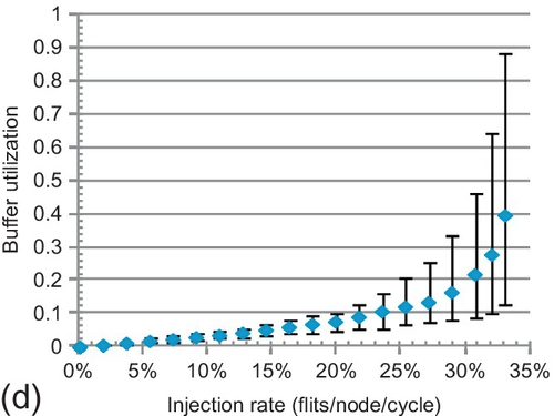
7.6.2 Buffer utilization
To delve into performance trends, the average buffer utilization of all VCs is shown in Figure 7.13. The maximum and minimum rates are given by error bars. Buffers can support high throughput; higher utilization generally means better performance. For LBS and CBS, the average rates are 13.0% and 19.2% at saturation. They inefficiently use buffers. LBS requires more free buffers for injection; its utilization is lower than that of CBS. Dateline's minimum rate is always zero; one VC is never used. For example, VC00 in Figure 7.2 is not used. This scenario combined with chained blocking limits its buffer utilization. Dateline's average and maximum rates at saturation are 23.2% and 71.8%, while these rates are 39.5% and 89.8% for FBFC-C.
7.6.3 Latency of short and long packets
FBFC's injection of long packets requires more buffers than short ones. Figure 7.14 shows latency compositions. “InjVC” and “NI” are delays in injection VCs and network interfaces. “Network” is all other delays. Long and short packets are treated the same in LBS and CBS; they show similar delays at injection VCs and inside the ring. Long packets have four more flits; they spend approximately four more cycles in network interfaces. With low-to-medium injection rates (20% or lower) in FBFC-C, the delays at injection VCs for long and short packets are similar. With higher loads, the difference increases. Even when saturated, they are only 3.4 and 3.2 cycles for the two patterns. FBFC-C does not sacrifice long packets. FBFC-C's acceleration of short packets helps long packets since short and long packets are randomly injected. Indeed, compared with FBFC-C, LBS and CBS sacrifice short packets. For example, with an injection rate of 20% for uniform random traffic, short packets spend 11.7 and 5.4 cycles in injection VCs for LBS and CBS, and 4.3 cycles for FBFC-C.


7.7 Evaluation on 2D tori
Section 7.6 analyzed the performance for 1D tori with buffer utilization and latency composition. This section thoroughly analyzes the performance for 2D tori with several configurations for further insights.
7.7.1 Performance for a 4 × 4 torus
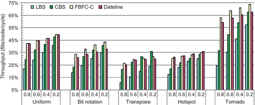
Figure 7.15 shows the performance for a 4 × 4 torus with the baseline configuration. The error bars in Figure 7.15a are average latencies of long and short packets. The average gains of FBFC-C over LBS and CBS are 92.8% and 34.2%. FBFC's high buffer utilization brings these gains. CBS shows an average gain of 45.7% over LBS, and the highest gain is 100% for transpose traffic. Most transpose traffic is between the same row and column; many packets change dimensions at the same router requiring the same port. CBS's low dimension-changing buffer requirement yields high performance.


Compared with the ring (Figure 7.12), the trends between FBFC-C and dateline for a 2D torus change. Dateline performs similarly to FBFC-C for uniform random and transpose traffic. A 2D torus has a dimension-changing step. The IDC counts of these patterns are both 1.5, and their hop counts are three. As a result, injection and dimension-changing factor significantly into performance. Dateline's low injection and dimension-changing buffer requirement brings gains. Dateline outperforms FBFC-C by 5.7% for hotspot traffic. This pattern sends packets from different rows to the same column of four hotspot nodes, exacerbating FBFC-C's injection limitation. FBFC-C outperforms dateline by 6.4% for bit rotation. Packets of bit rotation change dimensions by requiring different ports; the light congestion mitigates FBFC-C's limitation. These results do not consider frequencies. If routers are optimized to maximum frequencies, dateline's performance will drop.
As shown in Figure 7.15a, the delay difference between long and short packets is almost constant for LBS and CBS; long packets have approximately four cycles more delay. Dateline's difference is 6.2 cycles at saturation. FBFC-L's difference is 9.8 cycles. This is approximately three cycles more than for the ring; a 2D torus has one dimension-changing step. We measure the behavior after saturation by increasing the load to 1.0 flits per node per cycle. All designs maintain performance after saturation. DOR smoothly delivers injected packets. Adaptive routing may decrease performance after saturation because escape paths drain packets at lower rates than injection rates [13].
7.7.2 Sensitivity to SFP ratios
As discussed in Section 7.4.2, VCT routers' lookahead credit return overlaps incoming and outgoing packets; a packet can move to a VC with one free slot. This brings an injection or dimension-changing benefit for CBS over FBFC. CBS's packet injection begins with one free slot. FBFC-C's long packet injection needs five normal slots. Thus, SFP ratios affect trends between CBS and FBFC. Figure 7.16 shows the results of sensitivity studies on SFP ratios.
The performance of LBS and CBS increases linearly with reduced ratios; more long packets proportionally improve their buffer utilization. FBFC-C and dateline perform slightly better with lower ratios. They try to hold SA grants for entire packets; long packets reduce SA contention. Although FBFC-C's gains over CBS reduce with lower ratios, FBFC-C is always superior for most traffic patterns. FBFC-C performs 10.1% better than CBS for tornado with a 0.2 ratio. Tornado sends traffic from node (i, j) to node ((i + 1)%4, (j + 1)%4). Each link delivers traffic for only one node pair; there is no congestion. Transpose is different; CBS outperforms FBFC-C with ratios of 0.4 and 0.2. This pattern congests turn ports, emphasizing CBS's injection benefit.
We also experiment with a 64-bit flit width; the short and long packets have one and nine flits. With longer packets, the negative effect of regarding short packets as long ones in LBS and CBS becomes more significant. Meanwhile, FBFC-C needs more slots for long-packet injection. These factors result in trends for a 64-bit configuration similar to those in Figure 7.16.
7.7.3 Sensitivity to buffer size
We perform sensitivity studies on buffer sizes. In Figure 7.17a, CBS, FBFC-C, and FBFC-L use minimum buffers that ensure correctness. They use five, five, and six slots. Dateline uses two three-slot VCs. In Figure 7.17b, bubble designs use a 15-slot VC, and dateline uses two eight-slot VCs. Although FBFC-C's injection limitation has higher impact with fewer buffers, dateline performs only 7.6% better than FBFC-C with five slots per VC. Dateline's shallow VCs (three slots) cannot cover the credit round-trip delay (five cycles), making link-level flow control the bottleneck [19]. FBFC-C's gain over CBS increases with fewer buffers. The gains are 26.6% with 15 slots per VC, 41.4% with 10 slots per VC, and 121.8% with five slots per VC. From a comparison of Figures 7.15a and 7.17a, CBS with 10 slots per VC is similar to FBFC-C with 5 slots per VC. With half as many buffers, FBFC-C is comparable to CBS. LBS with 15 slots per VC (Figure 7.17b) has a gain of only 5.2% over FBFC-C with five slots per VC.
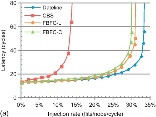
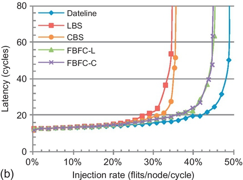
LBS almost matches CBS with 15 slots per VC. More buffers mitigate LBS's high injection buffer limitation. Additional results show that with abundant buffers, bubble designs perform similarly; there is little difference among them as many free buffers are available anyway. The convergence points depend on the traffic. For example, owing to congested ports in transpose, at least 30 slots per VC are needed for LBS to match CBS. For uniform random, 50 slots per VC are needed for CBS to match FBFC. Many buffers are required for convergence, which makes high buffer utilization designs, such as FBFC, winners in reasonable configurations.
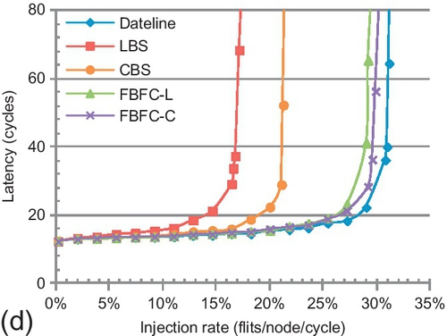
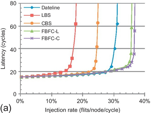
7.7.4 Scalability for an 8 × 8 torus
Figure 7.18 explores scalability to an 8 × 8 torus. Two buffer sizes are evaluated: one assigns 10 slots and the other assigns five or six slots (the same as Figure 7.17a). As the network scales, the traffic's hop count increases, exacerbating dateline's limitation for packet forwarding. Meanwhile, the IDC counts are similar to those of a 4 × 4 torus. Thus, FBFC-C's injection bottleneck is masked in larger networks. With 10 slots, FBFC-C outperforms dateline for all patterns. The largest gain is 26.5%, for tornado, whose average hop count is seven. With five slots, FBFC-C outperforms dateline for four patterns. Larger networks place greater pressure on buffers, worsening inefficient buffer utilization of LBS and CBS. With 10 slots, FBFC-C has a gain of 82.5% over CBS for uniform random, while it is 41.4% in a 4 × 4 torus. With 10 slots, the average gains of FBFC-C over LBS and CBS are 107.2% and 40.1% for the 8 patterns. With five slots, the average gain of FBFC-C over CBS is 78.7%.

7.7.5 Effect of starvation
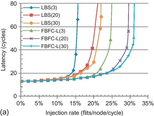
For LBS [10] there is limited discussion of starvation; CBS [13] relies on adaptive routing and therefore does not address starvation. We analyze starvation in a 4 × 4 torus. Reducing buffers makes starvation more likely. We use the same buffer size as in Figure 7.17a (LBS uses 10 slots) with uniform random. The results for larger networks or other patterns are similar.
Starvation in LBS and FBFC-L is essentially the same. Figure 7.19a shows their performance with three STVs. They perform poorly with the three-cycle STV. A small STV causes a router to frequently assert the “starve” signal (Figure 7.9) to prohibit injection by other nodes, which negatively affects overall performance. We also evaluate the saturation throughput with several STVs ranging from three to 50 cycles. LBS and FBFC-L perform better with larger STVs until 30 cycles, and then their performance remains almost constant. We set the STVs in LBS and FBFC-L to 30 cycles.

CBS and FBFC-C can starve owing to the critical bubble stall. Also, FBFC-C has the same starvation as FBFC-L. FBFC-C uses two STVs, one for each type of starvation. We fix the STV in FBFC-C for the same starvation as FBFC-L to 30 cycles, and analyze the other type of starvation. As shown in Figure 7.19b, the smaller the STV, the higher the performance. The proactive transfer of the critical bubble does not prohibit injection; even with many false detections, there is no negative effect. In contrast, the performance drops if packets cannot be injected for a long time. With a 20-cycle STV, if one node suffers starvation, it will move the critical bubble after 20 cycles. Then it starts injecting packets. This lazy reaction not only increases the zero-load latency, but also limits the saturation throughput. Since the proactive transfer of the critical bubble needs two cycles, we set the critical bubble stall STV to three cycles.
7.7.6 Real application performance
Figure 7.20 shows the speedups relative to LBS for PARSEC workloads. FBFC supports higher network throughput, but system gains depend on workloads. FBFC benefits applications with heavy loads and bursty traffic. For blackscholes, fluidanimate, and swaptions, different designs perform similarly. Their computation phases have few barriers and their working sets fit into caches, creating light network loads. They are unaffected by techniques improving network throughput, such as FBFC.

Network optimizations affect the other seven applications. Both CBS and FBFC see gains. The largest speedup of FBFC over LBS is 22.7%, for canneal. Two factors bring the gains. First, these applications create bursty traffic and heavy loads. Second, the two VNs with hybrid-size packets have relatively high loads. Across the seven applications, VN0 and VN2, on average, have 70.8% loads, including read request, write-back request, read response, write-back ACK, and invalidation ACK. These relatively congested VNs emphasize FBFC's merit in delivering variable-size packets. Across all workloads, FBFC and CBS have average speedups of 13.0% and 7.5% over LBS.
Compared with synthetic traffic, the real application gains are lower. This is because the configured CMP places light pressure on network buffers. Other designs, such as concentration [19] or configuring fewer buffers, can increase the pressure. FBFC shows larger gains in these scenarios. For example, we also evaluate performance with five slots per VN. FBFC-C achieves an average speedup of 9.8% and a maximum speedup of 20.2% over CBS. Also, the application run time of FBFC-C with 5 slots per VN is similar to that of LBS with 10 slots per VN.
7.7.7 Large-scale systems and message passing
The advance of CMOS technology will result in hundreds or thousands of cores being integrated in a chip [9]. Some current many-core chips, including the 61-core Xeon Phi chip [28], codenamed Knights Corner, use the shared memory paradigm. Yet, cache coherence faces scalability challenges with more cores. Message passing is an alternative paradigm. For example, the 64-core TILE64 processor uses a message passing paradigm [58]. It remains an open problem to design an appropriate paradigm for large-scale systems [41]. We evaluate FBFC for both paradigms. As a case study, we use a 256-core platform organized as a 16 × 16 torus.
In large-scale systems, assuming uniform communication among all nodes is not reasonable [47], workload consolidation [37] and application mapping optimizations [14] increase traffic locality; we leverage an exponential locality traffic model [47], which exponentially distributes packet hop counts. For example, with distribution parameter λ = 0.5, the traffic average hop is 1/λ = 2, and 95% traffic is within 6 hops, and 99% traffic is within 10 hops. We evaluate two distribution parameters, λ = 0.5 and λ = 0.3.
The packet length distribution of shared memory traffic is the same as the baseline configuration in Section 7.5; 80% of packets have one flit, and the others have five flits. All designs use 10 slots per VN. We assume that the packet length distribution of message passing traffic is similar to that of Blue Gene/L; packet sizes range from 32 to 256 bytes [4]. With a 16-byte flit width, packet lengths are uniformly distributed between two and 16 flits. All designs use 32 slots per VN.
Figure 7.21 shows the performance. The overall trends among different designs are similar to the trend for an 8 × 8 torus (Figure 7.18). LBS and CBS are limited by inefficient buffer utilization. LBS is further limited by its high injection buffer requirement. Dateline's limitation for packet forwarding restricts its performance. FBFC efficiently utilizes buffers, and yields the best performance.

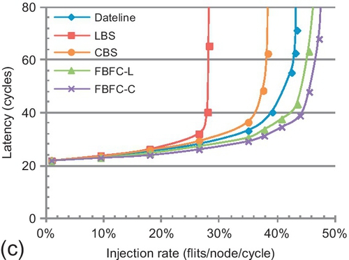
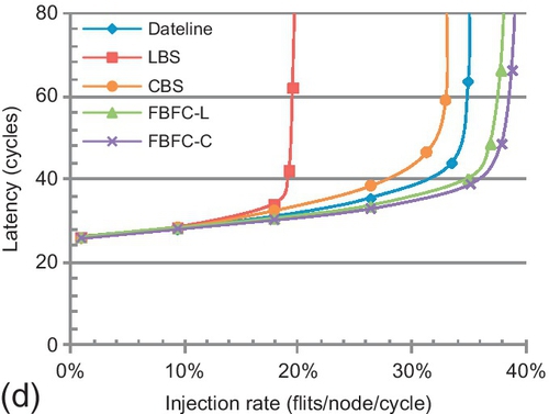
The performance gaps between FBFC and the other bubble designs depend on the distribution parameter λ. The smaller the λ, the larger the average hops. Larger average hops emphasize efficient buffer utilization; thus, FBFC had greater performance gains. For shared memory traffic, FBFC-C performs 47.7% better than CBS with λ = 0.5, and this gain is 66.5% with λ = 0.3. Message passing traffic shows similar trends. FBFC-C performs 18.7% better than CBS with λ = 0.5, and the gain increases to 23.8% with λ = 0.3.
FBFC's gain for message passing traffic is lower than for shared memory traffic. With λ = 0.5, FBFC-C performs 105.2% better than LBS for shared memory traffic, while it is 68.8% for message passing traffic. The packet length distributions are different. For shared memory traffic, the average packet length is 1.8 flits, and LBS regards each packet as a five-flit packet. The average packet length of message passing traffic is nine flits, and LBS regards each packet as a 16-flit packet. The maximum packet length of shared memory traffic is approximately 2.8 times the average length, while it is two times the average length for message passing traffic. This causes the drop in FBFC-C's gain for message passing traffic.
7.8 Overheads: power and area
In this section we conduct power and area analysis of our designs. We also compare tori with meshes.
7.8.1 Methodology
We modify an NoC power and area model [5], which is integrated in BookSim [29]. We calculate both dynamic and static power. The dynamic power is formulated as P = αCV2ddf, where α is the switching activity, C is the capacitance, Vdd is the supply voltage, and f is the frequency. The switching activities of NoC components are obtained from BookSim. The capacitance, including gate and wire capacitances, is estimated on the basis of canonical modeling of component structures [5].
The static power is calculated as P = IleakVdd, where Ileak is the leakage current. The leakage current is estimated by taking account of both component structures and input states [5]. For example, the inserted repeater, composed of a pair of pMOS and nMOS devices, determines the wire leakage current. Since pMOS devices leak with high input and nMOS devices leak with low input, the repeater leaks in both high-input and low-input states. The wire leakage current is estimated as the average leakage current of a pMOS and an nMOS device [5].
The router area is estimated on the basis of detailed floor plans [5]. The wires are routed above other logic; the channel area includes only the repeater and flip-flop areas. The device and wire parameters are obtained from the International Technology Roadmap for Semiconductors report [52] for a 32-nm process, at 0.9 V and 70 °C. As a conservation assumption, all designs are assumed to operate at 1 GHz.
We assume a 128-bit flit width. The channel length is 1.5 mm; an 8 × 8 torus occupies approximately 150 mm2. Repeaters are inserted to make signals traverse a channel in one cycle. The number and the size of the repeaters are chosen to minimize energy. VCs use SRAM buffers. We assume four VNs to avoid protocol-level deadlock. Allocators use the separable input-first structure [19]. We leverage the segmented crossbar [57] to allow a compact layout and reduce power dissipation. Packets are assumed to carry random payloads; two sequential flits cause half of the channel wires to switch.
7.8.2 Power efficiency
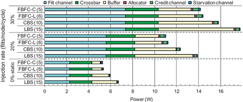
Figure 7.22 shows the power consumption of an 8 × 8 torus with uniform random traffic. The 0% injection rate bars refer to static power. All designs use 10 slots per VN. We divide the NoC into the flit channel, crossbar, buffer, allocator, credit channel, and starvation channel. LBS and CBS cannot support an injection rate of more than 35%. All designs consume similar amounts of power with the same load. The flit channel, crossbar, and buffer together consume more than 93% of the overall power. These components are similar for all designs. The allocator consists of combinational logic, and it induces low power consumption.


The credit channel of bubble designs has three wires; 2 bits encode four VCs and one valid bit. Dateline's credit channel has four wires; 3 bits encode eight VCs and one valid bit. The starvation channel of LBS and FBFC-L has six wires. Three bits identify one node among eight nodes of a ring. Two bits encode four VNs, and one valid bit. CBS's starvation channel uses six wires. “N2C” and “C2N” signals need 2 bits, and both signals use 2 bits to encode four VNs. FBFC-C handles two types of starvation; its starvation channel has 12 wires. These credit channels and starvation channels are narrower than flit channels; they induce low power consumption.
To clarify the differences, Figure 7.22b shows the allocator and sideband channel power consumption. Starvation channels are not needed for dateline. Yet, their activities are low. For example, FBFC-L's starvation channels remains idle until the injection rate is 34%. Dateline uses large allocators. Also, dateline's credit channel has one more wire than bubble designs. Dateline consumes more power than bubble designs with injection rates of 20% and 40%.
Although the credit channels of bubble designs are narrower than starvation channels, two reasons cause credit channels to consume more dynamic power. First, starvation channels are not needed for injection/ejection ports. An 8 × 8 torus has 384 credit channels and 256 starvation channels. Second, credit channels' activities are higher. VCT routers return one credit for each packet, and wormhole routers return one credit for each flit. Credit channels of LBS and CBS consume less dynamic power than FBFC.
Figure 7.23a evaluates the PDP. Compared with LBS and CBS, FBFC reduces latencies for heavy loads, improving PDP. With injection rates of 20% and 30%, FBFC-L's PDP is 5.9% and 56.9% lower than that of LBS. FBFC-L's PDP is 27.6% lower than that of CBS with an injection rate of 30%. Dateline's power consumption and latency are similar to those of FBFC. Its PDP is similar to that of FBFC. We also evaluate other traffic patterns. The trends are similar to those for uniform random traffic. All designs consume similar amounts of power, and FBFC's latency optimization reduces the PDP. For example, with transpose, FBFC-L's PDP is 34.2% lower than that of LBS with an injection rate of 15%, and its PDP is 28.9% lower than that of CBS with an injection rate of 20%.
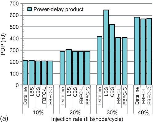

To show the impact of network scaling on power efficiency, Figure 7.23b gives the PDP on a 16 × 16 torus. The exponential locality traffic with λ = 0.3 in Section 7.7.7 is used; λ = 0.5 has a similar trend. Since FBFC optimizes latencies, it still offers power efficiency gains in larger NoCs. FBFC-L's PDP is 32.7% and 18.2% lower than that of LBS and CBS respectively for an injection rate of 30%, and its PDP is 26.6% lower than that of CBS for an injection rate of 40%.
As shown in Section 7.7.3, with half as many buffers, FBFC performs the same as CBS in an 8 × 8 torus. With one third of the number of buffers, FBFC performs similarly to LBS. Figure 7.24 gives the power consumption of bubble designs when they performs similarly. FBFC-C and FBFC-L use five and six slots per VN. CBS and LBS use 10 and 15 slots per VN. FBFC-C's buffer static power consumption is 49.8% lower than that of CBS, which results in FBFC-C's network static power consumption being 11.5% lower than that of CBS. FBFC-C's overall network static power consumption is 21.3% lower than that of LBS. High loads increase dynamic power consumption. Yet, even with an injection rate of 20%, FBFC-C's power consumption is still 20.4% and 10.4% lower than that of LBS and CBS respectively. Since now all designs perform similarly, FBFC's PDP is lower as well.
In summary, with the same buffer size, all designs consume a similar amount of power. FBFC's starvation channels induce negligible power consumption. Since FBFC significantly outperforms existing bubble designs, it achieves a much lower PDP, in both 8 × 8 and 16 × 16 tori. When bubble designs perform similarly with different buffer sizes, FBFC consumes less power and offers PDP gains.
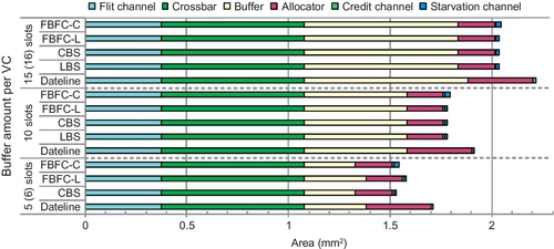
7.8.3 Area
Figure 7.25 shows the area results. The areas of the flit channel and crossbar are similar for all designs. With the same buffer amount, the area differences among designs are mainly due to the allocator, credit channel, and starvation channel. Dateline's allocator is approximately two times larger than that of bubble designs; this causes dateline to consume the greatest area. With 10 slots per VN, dateline's overall area is 7.4% higher than that of FBFC-L. When bubble designs perform similarly, FBFC's area benefit is more significant. CBS's network area with 10 slots per VN is 15.6% higher than that of FBFC-C with 5 slots per VN. The overall area of LBS with 15 slots per VN is 31.9% higher than that of FBFC-C with 5 slots per VN.
7.8.4 Comparison with meshes
We compare tori with meshes. The routing is DOR. The torus uses FBFC to avoid deadlock. On the basis of a floor-plan model [5], the mesh channel length is 33.3% shorter than that of the torus; it is 1.0 mm. Inserted repeaters make the channel delay be one cycle. Two meshes are evaluated. One uses a 128-bit channel width, which is the same as for the torus. Yet, its bisection bandwidth is half that of the torus. The other mesh uses a 256-bit width to achieve the same bisection bandwidth as the torus. All networks have the same packet size distribution. The 128-bit-width mesh uses 10 slots per VN. Its traffic has 80% five-flit packets and 20% SFPs. The 256-bit-width mesh uses five slots per VN. Its traffic has 80% three-flit packets and 20% SFPs.
Figure 7.26 gives the performance. Since the flit sizes of evaluated networks are different, the injection rate is measured in packets per node per cycle. The torus's wraparound channels reduce hop counts. For both patterns, the torus shows approximately 20% lower zero-load latencies than the mesh. With half of the bisection bandwidth, the saturation throughput of mesh-128bits is 24.2% and 37.0% lower than that of the torus for uniform random traffic and transpose traffic respectively. With the same bisection bandwidth, the saturation throughput of mesh-256bits is similar to that of the torus for uniform random traffic. The transpose traffic congests the mesh's center portion [43]; the saturation throughput of mesh-256bits is still 17.3% lower than that of the torus.
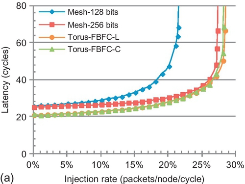

Figure 7.27 shows the power consumption and area. With the same channel width, the static power consumption of mesh-128bits is 30.5% lower than that of the torus; this is due to the optimization of buffers and flit channels. An 8 × 8 mesh has 288 ports with buffers, while an 8 × 8 torus has 320 ports. Two factors bring about power consumption reduction for mesh channels. First, an 8 × 8 mesh has 352 flit channels, while an 8 × 8 torus has 384 flit channels. Second, mesh channels are 33.3% shorter than torus ones. Thus, even 256-bit mesh channels consume less static power than torus ones. Yet, the 256-bit channel width quadratically increases crossbar power consumption. The overall static power consumption of mesh-256bits is 77.7% higher than that of the torus.
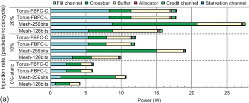

With high loads, mesh's center congestion increases dynamic power consumption; the benefit of mesh-128bits over FBFC-L decreases. With injection rates of 10% and 20%, its power consumption is 15.7% and 10.9% less than that of FBFC-L. With an injection rate of 20%, the channel power consumption of mesh-256bits is higher than that of FBFC-L. The PDP reflects power efficiency. With an injection rate of 10%, FBFC-L's PDP is 6.4% and 64.9% less than that of mesh-128bits and mesh-256bits respectively. Its power efficiency increases with high loads. With an injection rate of 20%, FBFC-L's PDP is 33.7% less than that of mesh-128bits.
The network area of mesh-128bits is 17.4% less than that of FBFC-L. The mesh-128bits uses fewer buffers and channels than FBFC-L. Owing to the large crossbar of mesh-256bits, its network area is 107.2% greater than that of FBFC-L.
We also compare a 16 × 16 mesh with a 16 × 16 torus. The static power and area benefits of mesh-128bits decrease with larger networks. The mesh's benefit of using fewer flit channels and ports decreases. In a 64-node network, the torus has 9.1% more flit channels and 11.1% more ports than the mesh. These values are 4.3% (1536 vs. 1472) and 5.3% (1280 vs. 1216) in a 256-node network. The static power consumption of mesh-128bits in a 16 × 16 mesh is 24.3% less than that of a 16 × 16 torus, and its network area is 13.4% less. The PDP is more favorable to FBFC. FBFC-L's PDP is 24.5% and 57.9% less than that of mesh-128bits and mesh-256bits respectively at an injection rate of 15% for exponential locality traffic with λ = 0.3.
In summary, although with the same channel width, the mesh consumes less power and occupies less area than the torus, its performance is poor owing to limited bisection bandwidth. With FBFC applied, the torus is more power efficient than the mesh for the same channel width. With the same bisection bandwidth, the mesh consumes much more power than the torus. Applying FBFC on the torus is well scalable.
7.9 Discussion and related work
7.9.1 Discussion
FBFC efficiently addresses the limitations of existing designs. It is an important extension to packet-size bubble theory. The insight of “leaving one slot empty” enables other design choices. For example, combined with dynamic packet fragmentation [24], a packet can inject flits with one free normal slot. When one flit's injection will consume the critical slot, this packet stops injecting flits and changes the waiting flit into a head flit. This design allows VC depths to be shallower than the largest packet. On the basis of similar insight, an efficient deadlock avoidance design is proposed for wormhole networks [12]. Its basic idea is coloring buffer slots white, gray, or black to convey global buffer status locally. This is different from our design. FBFC uses local buffer status with hybrid flow control which combines VCT and wormhole flow control. Also, we mainly focus on improving the performance for coherence traffic, which consists of both long and short packets.
Similarly to dateline and packet-size bubble designs, FBFC is a general flow control. It can be adopted in various topologies as far as there is a ring in the network. For example, Immune [49] achieves fault tolerance by constructing a ring in arbitrary topologies for connectivity. The ring uses LBS to avoid deadlock. Instead, FBFC can be used; it will support higher performance with fewer buffers. MRR [1] leverages the ring of a rotary router [2] to support multicast. The ring uses LBS. FBFC can be used as well. By configuring a ring in the network, FBFC can support both unicast and multicast for streaming applications [3]. Also, FBFC can support fully adaptive routing [13, 50]. Bubble designs use one VC; there is head-of-line blocking. FBFC can combine with dynamically allocated multiqueue [46, 55] to mitigate this blocking and further improve buffer utilization.
7.9.2 Related work
The Ivy Bridge [21], Xeon Phi [28], and Cell [31] processors use ring networks. The ring is much simpler than the 2D or higher-dimensional torus, and it is easy to avoid deadlock through end-to-end backpressure or centralized control schemes [31, 33]. The ring networks of these chips [21, 28, 31] guarantee injected packets cannot be blocked, which is similar to bufferless networks. Bufferless designs generally do not consider deadlock as packets are always movable [24]. Our research is different. We focus on efficient deadlock avoidance designs for buffered networks, which support higher throughput than bufferless networks. In addition to dateline [19], LBS [10], and CBS [13], there are other designs. Priority arbitration is used for SFPs with single-cycle routers [33]. Prevention flow control combines priority arbitration with prevention slot cycling [30]; it has deadlock with variable-size packets. The turn model [26] allows only nonminimal routing in tori. A design allows deadlock formation, and then applies a recovery mechanism [53].
FBFC observes that most coherence packets are short. Several designs use this observation, including packet chaining [42], the NoX router [27], and whole packet forwarding [38]. Configuring more VNs, such as seven VNs in Alpha 21364 [44], can eliminate coexistence of variable-size packets. Yet, additional VNs have overheads; using minimum VNs is preferable. DASH [36], Origin 2000 [35], and Piranha [6] all apply protocol-level deadlock recovery to eliminate one VN; they utilize two VNs to implement three-hop directory protocols. These VNs all carry variable-size packets.
7.10 Chapter summary
Optimizing NoCs for coherence traffic improves the efficiency of many-core coherence protocols. We observed two properties of cache coherence traffic: short packets dominate the traffic, and short and long packets coexist in an NoC. We proposed an efficient deadlock avoidance theory, FBFC, for torus networks. It maintains one free flit-size buffer slot to avoid deadlock. Only one VC is needed, which achieves high frequency. Also, FBFC does not treat short packets as long ones; this yields high buffer utilization. With the same buffer size, FBFC significantly outperforms LBS and CBS, and is more power efficient as well. When bubble designs perform similarly, FBFC consumes much less power and area. With FBFC applied, the torus is more power efficient than the mesh.