Virtual bus structure-based network-on-chip topologies†
Abstract
The need for scalable and efficient on-chip communication in future many-core architecture has resulted in the networks-on-chip (NoCs) design emerging as a popular solution. It is a common belief that packet-based NoCs can provide high efficiency, high throughput, and low latency for future applications instead of the conventional transaction-based bus. However, these superior features of NoCs apply only to unicast (one-to-one) latency noncritical traffic. Their multihop feature and inefficient multicast (one-to-many) or broadcast (one-to-all) support have made their use awkward when performing some kinds of communications, including cache coherence protocol and global timing and control signals, and some latency-critical communications. We present a virtual bus on-chip network, a new architecture of incorporating buses into NoCs in order to take advantage of both NoCs and buses in a hierarchical way. The point-to-point links of conventional NoC designs can be dynamically used as bus transaction links for bus requests. This can achieve a low latency while sustaining high throughput for both unicast and multicast communications at low costs. To reduce the latency of the physical layout for the bus organization, hierarchical redundant buses are used. Detailed network latency simulations and hardware characterizations demonstrate that the virtual bus on-chip network can provide the ideal interconnect for a broad spectrum of unicast and multicast scenarios and can achieve these benefits with inexpensive extensions to current NoC routers.
4.1 Introduction
The need for scalable and efficient on-chip communication in future many-core systems has resulted in the network-on-chip (NoC) design emerging as a popular solution [11, 31]. NoCs are conceived to be more cost-effective than the bus in terms of traffic scalability, area, and power in large-scale systems. Such networks are ideal for component reuse, design modularity, plug-and-play, and scalability, and they avoid the uncertainty of global wire delay perspectives. Recent proposals, including the 64-core TILE64 processor from Tilera [31] and Intel's 80-core Teraflops chip [11], have successfully demonstrated the potential effectiveness of NoC designs. However, most existing NoCs are based on the assumption that the vast majority of traffic is of a one-to-one (unicast) nature [6]. Their multihop feature and inefficient multicast (one-to-many) or broadcast (one-to-all) support have made it awkward to perform some kinds of latency-critical and collective communications. Examples include cache coherence protocols, global timing and control signals, and some latency-critical communications [20].
The packet-based NoC designs often use wormhole switching as the flow control mechanism; this delivers a packet in a pipelined fashion [5]. For long messages, the latency is insensitive to the distance traversed. However, it would be a problem for some short and urgent messages [18]. Another problem of current NoC design is that the performance of multicast is much lower than that of unicast in general. Multicast communication in NoCs is achieved by extending unicast, which sends each packet to all destination nodes or a subset of destinations, each of which in turn forwards the message to one or more other destinations in a multicast tree or path [19]. However, owing to inherent multicycle packet delivery latency and network contention, the multicast-packet overhead in NoCs is very high. A common approach is wormhole switching with multicast support [6, 19, 26]. But this method also needs routing time to the destinations before sending data and multihop time for sending data. So, the multicast overhead is still high.
It is interesting that conventional buses usually show lower packet latency than NoCs. The broadcast or multicast can be efficiently supported by a shared bus within one transaction. So, many recent NoC designs have taken advantage of transaction-based buses by integrating buses physically [20, 23, 25, 29]. Though on-chip wires are relatively abundant, use of a large number of dedicated point-to-point links leads to a large area footprint and low channel utilization. Some researchers have proposed the idea of express channels in NoCs, namely using dedicated NoC connections as buses that are dynamically selected such as express virtual channels (EVCs) [17] and NoC hybrid interconnect (NOCHI) EVCs [15]. These approaches can reduce the effective network diameters of NoC designs, but they do not consider multicast or broadcast problems.
In this chapter, we present the virtual bus (VB) on-chip network (VBON), a new architecture for incorporating buses into NoCs in order to take advantage of both NOCs and buses. It uses the VB as the bus transaction link dynamically for bus requests, which is built upon the point-to-point links of conventional NoC designs. The VBON topology has the advantage that it does not use extra physical links. This achieves low latencies while supporting high throughput for both unicast and multicast communications at low costs. To reduce the latency of the physical layout for the bus organization, two methods are used. The first one is the hierarchical clustered bus structure, which divides the chip into several clusters with bus-connecting routers in a cluster. Each of these clusters is connected via intermediate routers. The second one is called the redundant bus, which uses several buses instead of one bus to constrain the longest distant of the network to a bearable bound.
4.2 Background
In this section, we discuss related work on improving the performance metrics of packet-switched NoCs.
Improving the performance metrics of packet-switched NoCs by integrating a second switching mechanism has been addressed in several works, such as integrating a physical bus [20, 23, 25, 29]. These buses typically serve as a local mechanism in the NoC interconnect hierarchy [23, 25]. Then the delivery of data over short distances does not involve the multihop network. In Ref. [29], the NoC network was reported to be created totally on the basis of a bus in a hierarchical way. Lower energy consumption and a simple network/protocol design are claimed. The hybrid bus-enhanced NoC design adds a global bus as a low-latency broadcast/multicast/unicast medium [20]. The reconfigurable NoC proposed in Ref. [28] reduces the hop count by physical bypass paths. Though our works also have some similarities with this reconfigurable NoC, we reduce the hop count by virtually bypassing the intermediate routers and further consider the multicast problem.
Another approach is the express topology, which employs long links between nonlocal routers to reduce the effective network diameter. The long links can be created physically (adding extra router ports, larger crossbars, and extra physical channels [10, 14]) or virtually (opportunistically bypassing router pipelines at intermediate networkhops [15–17, 21, 22]). The EVC approach [17] improves the energy-delay throughput in the network that lets packets bypass intermediate routers. Further improvements are done by NOCHI EVCs [15], enabling more bypassing of nodes and reducing the traversal latency and dynamic power with global interconnect circuits. Though the express topology can reduce the unicast latency of NoC communication, it does not consider the multicast or broadcast communication pattern, which is the main problem this chapter tries to solve.
The support for multicast communications in NoCs may be implemented in software or hardware. The software-based approaches [3] rely on unicast-based message passing mechanisms to provide multicast communication. Implementing the required functionality partially or fully in hardware has proved to improve the performance of multicast operations such as the connection-oriented multicast scheme in wormhole-switched NoCs [19], the XHiNoC multicast router [26], and virtual circuit tree multicasting [6].
This chapter proposes the use of a VB as an attractive solution for packet-based NoCs in latency-critical and multicast communications. Though the concept of a VB has been explored for off-chip networks [4], as power, area, and latency constraints for off-chip routers versus on-chip routers differ substantially, prior off-chip routers are not directly suitable for on-chip usage. The proposed VBON design with its microarchitecture and protocol are discussed in detail to overcome the wire delay limitation of the conventional on-chip bus.
4.3 Motivation
Before describing the VBON architecture, we first introduce the baseline on-chip interconnection networks and their problems, and then briefly discuss the advantages of transaction-based bus communication.
4.3.1 Baseline on-chip communication networks
The huge communication demands of applications have made the on-chip communication network the most important part of chip design. The interconnect structure has been changed from bus-based communication to an NoC approach as will be discussed in detail in the following subsections.
4.3.1.1 Transaction-based bus
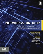
Traditionally, shared-bus-based communication architectures are popular choices for on-chip communication. Figure 4.1a shows a bus example architecture which is regarded as a transaction-based communication architecture. The bus is a simple set of wires interconnected to all the master nodes, slave nodes, and an arbiter in a single way. A bus transaction generally consists of first establishing a connection between communicating pairs before sending data (a role endorsed by the bus arbiter). So the bus can be a centric architecture in which all the components are tightly coupled. In one transaction, the master node can reach all the slave nodes directly and immediately. This is very efficient when connecting only a few tens of intellectual property cores. However, these transactions are necessarily serialized, causing heavy contention and poor performance when more cores are integrated. Thus, the bus structure fails to satisfy the requirements of future parallel applications. Furthermore, the global wires introduced by the bus also cause scalability, energy consumption, and performance problems.
4.3.1.2 Packet-based NoC
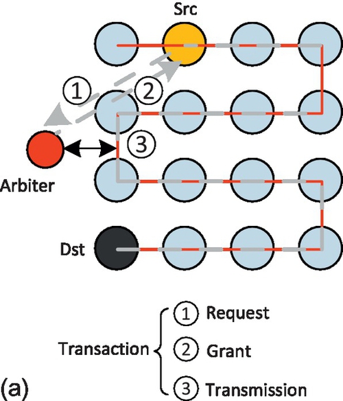
NoC communication architectures connect the processing and storage resources via a network. Communication among various cores is realized by generating and forwarding packets through the network infrastructure via routers. By eliminating the global wires used in the bus, the NoC approach can provide high bandwidth and scalability. The 2D mesh is by far the most exploited topology since it is particularly easy to implement on current planar CMOS technology. Figure 4.1b shows an example of the mesh network. It consists of 16 tiles arranged in a 4 × 4 grid, where each tile is connected to its four neighbors (with the exception of the edge tiles). Because only neighboring nodes are connected, packets that need to travel long distances suffer from large hop counts. Current packet-based on-chip networks have made each packet need to go through router pipelines, typically four to five stages at each hop [5], and involve multiple hops according to the distance. This widens the gap between the ideal interconnect and the NoC design. A more serious problem may occur when multicast or broadcast communications are activated in that their latency and throughput features usually do not satisfy the demand of applications.
4.3.2 Analysis of NoC problems
We will introduce a model to evaluate the latency of NoC communication with both unicast and multicast/broadcast traffic. The model considers conventional pipeline routers [9] and targets wormhole flow control under deterministic routing algorithms.
4.3.2.1 Multihop problem
The latency of a unicast message is regarded as the time from the generation of the unicast message at the source node until the time when the last flit of the message is absorbed by the destination node. So the service time of a unicast packet, TNoC, is given by
where Ts is the router service time for the header flit and Tb is the number of cycles required by a packet to cross the channel. Since the remaining flits follow the header flit in a pipelined fashion, Tb is simply the quotient of the packet size, S, and the channel width, W:
We note that Ts is a function of the router design and its hop number, H, including the time to traverse the router (tR) and the link (tL):
Here, thop is the latency of each router hop, tBW is the time the flit spends in the buffers, tVA and tSA are the times the flit spends in arbitrating the buffer and switching resources, and tcrossbar is the time to actually traverse the router.
In the ideal case, the unicast delay for NoC networks, Tideal, should be the transmission delay of the physical link. For each hop, the ideal network latency, indicating the intrinsic network delay, can be written as
So the total ideal delay, Tideal, can be written as
Compared with the ideal network latency, Tgap, indicating the extra router pipeline and resource contention latency in the NoC network design, can be written as
From Equation (4.6), it can be seen that if we want to reduce the unicast latency of the NoC, we should reduce the number of transmission hops, the processing time of router pipelines, and the contention time caused by multiple packets waiting for transmission.
4.3.2.2 Multicast problem
The multicast latency can be defined as the time from the generation of the message at the source node until the time when the last flit of the multicast message is absorbed by the last destination of the multicast message among messages leaving injection ports. We use unicast-based message passing mechanisms to provide multicast communication. These multicast packets are broken down into multiple unicasts by the network interface controllers as the packet-switched routers are not designed to handle multiple destinations for one packet. Then the service time of a multicast packet, TNoC_mc, is given by
where tinject is the injection time of the multicast flit. Since a multicast packet has multiple destinations, this causes competition at the network interface for injection into the network. This adds significant delays to the packet communications. From Equation (4.7), it can be seen that we can reduce the multicast delay in two ways. One is to reduce the unicast traffic caused by multicast packets so that the competition for network resources can be reduced. The other is to choose a good routing algorithm so that the communication path to each destination is the shortest.
4.3.3 Advantages of a transaction-based bus
When the traffic is transmitted by a conventional bus, it allows only one master to transfer data over the bus at a time. Since each packet has many flits to transmit, the bus generally supports burst transfer. The latency of the burst transfer in a bus can be represented as
Compared with the conventional NoC, the decreased latency can be written as

Equation (4.9) shows that the bus mechanism eliminates the delay caused by the NoC multihop feature, and its delay is close to that of the ideal communication mechanism. However, the competition for transmission resources in the shared bus is more serious than in the distributed NoC, which increases the time of bus arbitration, tarbiter.
Another advantage of the bus is that it transmits all the data in a broadcast way, so the communication amount generated by a multicast or broadcast packet is the same as with a unicast packet as shown in Equation (4.8). This means that the bus has a natural advantage for multicast communication.
Though the benefits of the bus are appealing, the bus is poorly scalable. When the number of nodes that connect to the bus is larger than a certain number (typically more than 10), the performance and power metric of the bus will decline rapidly. Therefore, how to incorporate the bus mechanism in the context of an on-chip network to maximize its advantages requires further study.
4.4 The VBON
4.4.1 Interconnect structures
The VBON architecture is introduced as a simple and efficient NoC design to offer low latency for both unicast and multicast/broadcast communication. The key idea of the VBON is to integrate the VB into the network, and to use the VB to bypass intermediate routers by skipping the router pipeline or transmit to multiple destinations in a broadcast way. Differently from one set of proposals which employ additional physical links to construct the local buses [20, 23, 25], the bus transaction link in a VBON is constructed dynamically for bus requests from the existing point-to-point links of conventional NoCs.
The concept architecture for a VBON with a baseline 8 × 8 mesh is presented in Figure 4.2. To improve the characteristics of the bus, we organize the VBs in a hierarchical way, which can reduce the physical layout effort for the bus organization. The chip is divided into several clusters of cores, with VBs connecting routers in each cluster. These VBs between clusters are then connected via intermediate cores. As illustrated in Figure 4.2, four VB clusters (4 × 4, 5 × 4, 5 × 5, 4 × 5) are configured in an 8 × 8 NoC to ensure that the intermediate routers exist between each cluster pair.
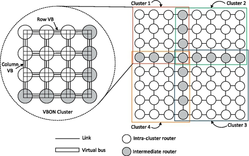
In each cluster, if all the routers are connected through one global bus, then the length is of O(N) complexity. To reduce this physical length of the VB, the redundant bus method is introduced, which uses several buses instead of one to control the VB length within a bearable bound. In the example shown in Figure 4.2, the 2D mesh is configured with row and column VBs in each cluster. Thus, each VBON router is connected to one row VB and one column VB. Instead of one transaction in the global bus [29], two transactions are needed for communications between different row and column VBs. But the length increases at a much lower rate of ![]() . This is important for the physical layout of VB organization. Furthermore, since every row or column bus has its own access control, multiple independent bus transactions can coexist at the same time.
. This is important for the physical layout of VB organization. Furthermore, since every row or column bus has its own access control, multiple independent bus transactions can coexist at the same time.
Since the VB shares network links with the underlying NoCs and it applies a simplified flow control, it is a light-weight bus, and is much less expensive than conventional system buses in terms of area, power, and system complexity. The VB does not utilize the segmentation, spatial reuse, split transactions, and other costly throughput boosting mechanisms. The VB provides a high-efficiency and low-latency communication structure that outperforms the conventional NoC in terms of power and latency for short unicast, broadcast, and multicast transactions.
When the bus transaction needs to traverse several VB segments, we retain the same arbitration scheme for different VB segments. This organization essentially allows each transmission across different VBs to be pipelined, which not only increases throughput, but also reduces the contention for the buses, bringing performance improvement.
4.4.1.1 Wire delay consideration
Technology scaling has resulted in a steady increase in transistor speed. However, unlike transistors, global wires that span the chip show a reverse trend of getting slower with the shrinkage process. Modern processors are severely constrained by the wire delay. However, wire delays are somewhat tolerable when repeaters are judiciously employed [2]. Figure 4.3 shows the interconnect delay scaling from the prediction of the International Technology Roadmap for Semiconductors 2008 report [27]. This wire delay prediction can help us to decide the optimal length of VBs in many-core processor chips. The table in Figure 4.3 shows the wire transmission length per nanosecond under different technology nodes. We can see that with repeaters, the delay of transmitting signals on global wire can be reduced from 2000 to 120ps/mm with 22 nm technology, i.e., the wire data can be transmitted at a rate of 8 mm/ns.

If we assume the chip die area is 10 × 10 mm2 and the frequency is 1 GHz, the data can be transmitted in a relatively long range across the chip in one cycle. Therefore, in this chapter, we consider only the case that a VB can transmit in one cycle. If a higher frequency is required, the maximal length of the VB may be decreased or one VB segment can be transmitted in multiple cycles.
4.4.2 The VB mechanism
4.4.2.1 The VB construction
Figure 4.4 illustrates the mechanism for constructing the VB. It is established by bypassing the existing datapaths of the conventional router. Though only the concept structure of the row/column VB implementation is presented, this bypassing method can be used in any other type of VB. Each node is simply composed of some switches that can establish internal connections among its ports. In addition, each node has some simple controller logic. The controller can read control signals from bus arbiters and configure the internal switches. Four possible node configurations for the internal switches are displayed in Figure 4.4a, i.e., (N → S), (S → N), (W → E), and (E → W). The connections among the controller and the ports are not shown in Figure 4.4 for simplicity.
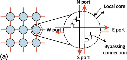
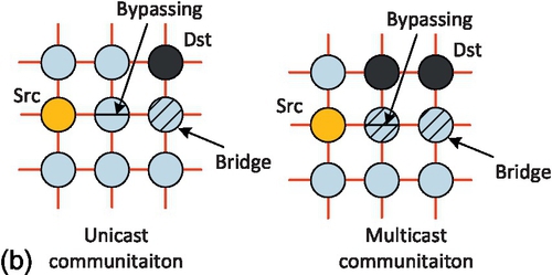
Figure 4.4b gives two examples for how to construct the row/column VB. There are bypassing nodes for transmission in each row or column VB, and bridge nodes for transmission between the row and column VBs. So the real transmission in the VB link can be completed by bypassing existing router pipelines. This is different from the multihop transmission in the conventional NoC design. Through a little logic overhead in the basic router and dynamic link sharing between NoCs and buses, the VBON improves the conventional NoC while preserving all its essential features, including high efficiency, high throughput, and high bandwidth for unicast traffic, as well as scalability and low power consumption.
The transmission to multiple destinations on a single row or a single column is enough with only one VB. However, in several cases, the destinations are scattered so as to be distributed on multiple rows or columns. For multiple destinations on different rows or different columns, a single-row VB and multiple-column VBs have to be established. Their arbitrations and data transmissions are done in a dimensional order fashion.
4.4.2.2 VB arbitration
Figure 4.5 shows the signal lines for one row VB in an 8 × 8 hierarchical VBON system. Since signal lines for column VBs are the same as for the row VBs, they are not shown in the figure. The row VB presented is segmented into two row VBs, and each has an arbiter router in the middle of the VB. The Request and Grant signals are used for the bus arbitration. To arbitrate for the VB, a router must send the Request signal to a central arbiter structure, which then sends back the Grant signal to one of the requesters. To keep the arbiter design simple, we assume that each node has only one outstanding bus request, the request signal is activated until the Grant signal is received, and there is no buffering of requests at the arbiter. The Burst signal is used to specify whether the bus communication is a burst mode (transmitting more than two flits consecutively) or not.

The bus mode signal (Mode[1:0]) indicates the bus transaction types, such as unicast, multicast, and broadcast. The bus ready signal (Ready) serves two purposes. One is related to the VB start-up procedure. When a router is trying to get the bus grant through the bus request signal Request, the other routers on the same row/column VB assert the Ready signal. The other purpose is for the end-to-end flow control of the VB transaction. When the buffer in the destination is filled with flits, the destination deasserts a Ready signal, then the arbiter will be able to pause the bus transaction.
The Pause and Dir signal pair is used to control the pausing logic for bypassing the intermediate routers. The Pause signal specifies whether the pausing logic is activated, and the Dir signal specifies the direction of the VB transmission link.
The VB arbitration algorithm is illustrated in Figure 4.6. It assumes that the number of VBs is M. It first checks whether the VB node is ready for transmission by reading the Ready signal. If it is ready, the arbitration is activated. To fairly access the VB, we use the circular priority to select the winning node for further processing. Lines 6-10 in the algorithm generate the pausing signals for the bypassing nodes. Since the two ends of the VB and the data sender are obviously not the bypassing nodes, pause signals should not be generated for them. The time complexity of this arbitration algorithm is low because M is small (M = 4 in our VB configuration). It is not the timing-critical part in the proposed router.

4.4.2.3 Packet format
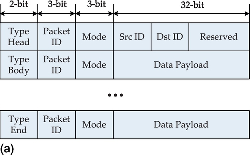
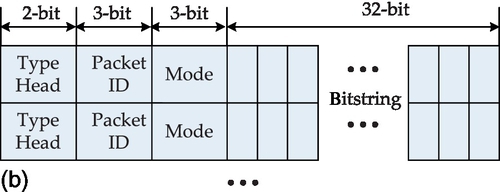
In order to support multicasting, we expand the packet format into that shown in Figure 4.7. We explain the packet fields as follows. The 38-bit packet format for unicast is shown in Figure 4.7a. The packet consists of the header flit followed by payload flits. Three additional 3-bit heads are the Type, ID (identity), and Mode bits. The Type can be header, data body, and the end of data body (last flit). The Mode can be the unicast, multicast, and broadcast communication pattern for different packet formats. The source and target addresses of the packet are asserted in the header flit. Passing a communication segment of the NoC, each packet has the same local identity number (ID tag) to differentiate it from another packet. The local ID tag of the data flits of one packet will vary over different communication segments in order to provide a scalable concept. Figure 4.7b shows the packet format for multicast services. The target addresses are specified in the bitstring field. Each bit in the bitstring represents a node, the hop distance of which from the source node corresponds to the position of the bit in the bitstring. The status of each bit indicates whether the visited node is a target of the multicast or not. For broadcast communication as shown in Figure 4.7c, all nodes in the NoC are receiver nodes, so they can be specified implicitly.
4.4.2.4 VB operation
We apply the procedure used in the connection-oriented multicasting NoC [19] in the VB operation. The VBs can be dynamically established, and all conflicting ongoing messages can be paused during the VB transmission. This consists of three phases, VB setup, communication, and VB release:
(1) VB setup. First the source node sends a request to the arbiter to access the VB. In order to resolve VB requests from many sources, the row ID of a node stands for its priority. The row ID of highest priority is able to continue its VB transaction. As a result, others withdraw their VB requests, which will be retried afterwards. When the bypassing circuits for the VB are established, the existing routing data are frozen intact in the flit buffers.
(2) Communication. The VB data is being transmitted to the destination nodes. Except for the broadcast packet, the destination information is needed in multicast or urgent unicast packets. At the beginning of data transmission, the source transfers encoded destination vectors through point-to-point links, and then transfers the following raw data. Once the vectors have been received, the nodes can determine which nodes are destinations or bridges connected to the destinations in the other dimension.
(3) VB release. After the VB transmission, the datapath seized by the VB is released. The paused routing data can continue to proceed to its destination.
The transition state of VB operation is illustrated in Figure 4.8. If the source and destination nodes belong to the same bus segment (the same row or column), the packet can be transferred by using one VB operation (IDLE → SETUP → BUSY → IDLE). If they are in different bus segments (different rows or columns), multiple VB operations are used.

The bridge node is responsible for transition from one row VB to one column VB. When this happens, the flits from the row VB can be stored in the bridge node and then they request another VB operation. Since a row VB has only one packet at a time, there is no contention for the buffer in the same bridge node.
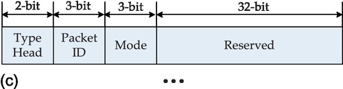
A simple and illustrative timing diagram of one VB operation is shown in Figure 4.9. The VB transmits four flits in the burst mode, where three different roles of nodes are involved: the source node Src, the intermediate node Inter, and the destination node Dst. The signal names begin with the type of node that connects to the signal. When the Src node requests the VB transmission by asserting the Request signal, it also asserts the Burst signal. Then the VB arbiter grants the VB access according to the Ready signals from other nodes and the priority information. At the same time, it generates the Pause and Dir signals for bypassing Inter nodes. Then the flit data can be sent to the Dst node. After the VB transmission, the Src node withdraws the Request signal, and the arbiter will release the VB in the next cycle.
4.4.2.5 A simple example for VB communication
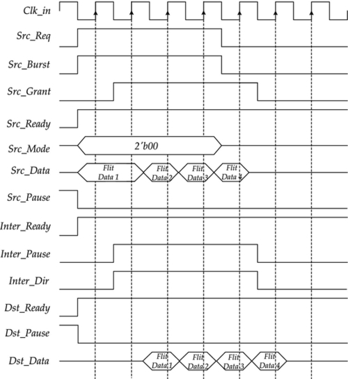
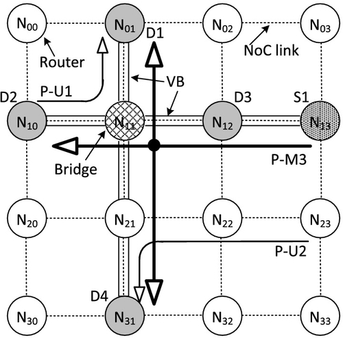
Figure 4.10 shows a simple example for VB communication, which includes three packets. We assume that the transmission times of three packets overlap and the packet ID indicates the message generation order. Packet1 and Packet2 are unicast messages, and these two packets can be transferred concurrently since their required channels are disjoint. In this time, node N13 generates a multicast packet Packet3 which goes to destination nodes: N01, N10, N12, and N31. Two VBs are involved in the communication process for Packet3. The row VB (VBR1, from node N10 to node N13) is first established after the arbitration. Then the column VB (VBC1, from node N01 to node N31) is established. Node N11 is the bridge between two VBs. When the flits of Packet3 are sent to node N11, they are stored in VB buffers and node N11 requests the column VB transmission. The ongoing flits of P-U1 and P-U2, which share the same datapath with the two VBs, are just frozen, because VBs have the highest priority to transmit.
4.4.3 Starvation and deadlock avoidance
There are two cases causing starvation scenarios in the VBON. The first case is when a node along the VB path always has incoming VB flits to serve, and flits buffered locally at the node may never get a chance to use the physical channel. This is because higher priority is given to VB flits. A simple solution to avoid such a scenario is to maintain a count of the number of consecutive VB operations for which it has served. After serving for n consecutive VB operations, the VB node sends a starvation on token to the arbiter if it has conventional NoC flits which are getting starved. Upon receiving this token, the VB arbiter stops granting VB requests for the next p consecutive cycles. Hence, the starved locally buffered NoC flits can now be serviced. The n and p are design parameters which can be set empirically.
The second case for starvation scenarios is caused by unfair priority policies between VB operations. We suggest that the row VB independently increases the bus priority of the respective nodes by way of a bus priority shifter. Thus, all the nodes on the same row have equal opportunities in the row VB. The bus priority of the column VB rotates like that of the row VB, but in contrast the column VB alters simultaneously the priority of all the columns. In this way, all the nodes on the same column have equal opportunities.
Another critical issue when designing NoCs is to guarantee deadlock-free operation. Routing-dependent deadlocks occur when there is a cyclic dependency of resources created by the packets on the various paths in the network. In the case of a VBON communication using VBs, the deadlock conditions are not generated, since VBs are used in order of the row VB and the column VB in the dimensional order fashion.
4.4.4 The VBON router microarchitecture
Figure 4.11 shows the microarchitecture of the proposed VBON router. It shows the implementation details of one input port and one output port of the router. The differences from a generic router are shaded. In order to implement the VB functionality, three components are added or modified: the VB channel, pause logic, and VB allocator. For each port, there is a VB channel (VC0) devoted to establishing VB connections. There are two datapaths in the VB channel: the virtual channel (VC) and the VB bypassing datapath. When the router is used as a bridge (between row and column VBs, or between different bus segments) or the injection node, the VC is used. When the router is used as a bypassing node, the VB bypassing datapath is used. To implement the bypass path, a two-to-one multiplexer is required at the output of the buffer, and this can isolate the buffer and connect the input to the output through the crossbar switch.
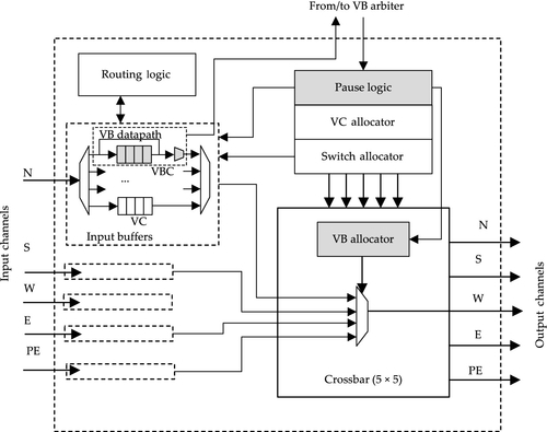
The pause logic is responsible for the VB protocols. It receives the control signals from the VB arbiter and generates inner control signals for VB channels and the VB allocator. If the pause signal is not activated, then the VC is selected on the basis of the outcome of the routing function, VC allocator, and switch allocator, as in traditional packet-switched networks. Otherwise, the VB data is directed to the crossbar input. Since VB data have higher priority over NoC packets, the NoC packets overlapping with the VBs, when forming the VBs, should be paused by the pause logic. However, these ongoing routing packets interrupted by the VB should be resumed after VB operation, so a register for each link is required in order to keep track of the routing information of the paused packets.
Each output port contains a VB allocator which takes the signals from the pause logic as well as the output of the switch allocator as inputs, and allocates the output port to the input port of the VB when the pause signals activate. Otherwise, the allocation is done according to the output of the switch allocator, as in traditional packet-switched NoCs.
Supporting VBs in a baseline packet-switched router involves adding a bypassing datapath in each input port, the pause logic for the VB protocol, a simple VB allocator at each output port, and some wires to propagate the control signals. There is minimal impact on the baseline router architecture and a negligible area overhead is imposed.
4.5 Evaluation
In this section, we present a detailed evaluation of the VBON with a baseline 2D mesh topology. We will describe the evaluation method, followed by results obtained using both synthetic and application traffic patterns. Afterwards, the effect of the proposed method on the NoC hardware cost is evaluated.
4.5.1 Simulation infrastructures
The purposes of our experiments are
(1) to compare VBON multicasting with state-of-the-art router designs unicasting multiple packets with each in a separate packet,
(2) to investigate the impact of the multicast traffic on the unicast traffic in a mixed unicast-multicast network, and
(3) to evaluate the scalability of the multicast scheme.
To evaluate the proposed VBON approach, we implemented its architecture using a SystemC-based cycle-level NoC simulator, which is modified from a NIRGAM simulator [8]. The simulator models a detailed five-stage router pipeline. We can change various network configurations, such as the network size, topology, buffer size, routing algorithm, and traffic pattern. In the following text, some specific issues related to the simulation, including the reference designs, network configuration, and traffic generation, are introduced. We integrated Orion [30], an architecture-level network energy model, in our simulator to calculate the power consumption of the networks. The power results reported by Orion are based on an NoC in 90 nm technology.
4.5.1.1 Router choices for comparison
We compare various characteristics of the proposed VBON schemes against two existing baseline packet-switched networks: the basic router [9] and the NOCHI EVC router [15].
The basic router is representative of conventional NoC designs. It originally had a four-stage router pipeline. The first stage is the buffer write; the routing computation (RC) occurs in the second stage. In the third stage, VC allocation (VA) and switch allocation (SA) are performed. In the fourth stage, the flit traverses the switch. Each pipeline stage takes one cycle, followed by one cycle to do the link traversal to the next router. To shorten the pipeline, the basic router uses lookahead routing [7] and the speculative method [24]. Lookahead routing determines the output port of a packet one hop in advance. That is to say while the flit is traversing the switch, a lookahead signal is traveling to the next router to perform the RC. In the next cycle, when the flit arrives, it will proceed directly to SA. The speculative method can eliminate the VA and SA stage by causing flits to directly enter the switch traversal pipeline.
The NOCHI EVC router was chosen because its concept is similar to our work. It is an optimized design based on the EVC router design [17]. A conventional EVC router sets up virtual express paths in the network that let packets bypass intermediate routers, thus improving the energy-delay throughput of NoC interconnects. We can regard this virtual express path as a multiple-stage VB. Though it uses the low-latency benefit of the bus mechanism for unicast communication, it does not use the broadcast feature of the bus, leading to some limitations. First, buffers at an EVC's end point must be managed conservatively to ensure that the destination router (the EVC end point) can accept the traffic. This leads to buffer overprovision and underutilization. The second deficiency is that VCs must be partitioned between different express paths statically, and the control latency limits the number. To overcome these limitations, the NOCHI EVC router is proposed to enable single-cycle control communication across all nodes in a row or column of a mesh network through G-line. Using timely information reduces the demand on router buffers as well as the number of buffers needed to sustain a specific bandwidth. In a sentence, the NOCHI EVC approach is a very effective method for unicast communication, but it does not support multicast communication.
Table 4.1 lists the comparison results for the three different NoC designs. The comparison parameters are
Table 4.1
Comparison of Router Designs
| Parameter | Basic Router | NOCHI EVC Router | VBON Router |
| Overhead | – | G-lines, EVC controller | VB control lines, VBON controller |
| Bus link | – | Virtual | Virtual |
| No. of hops | Multiple hops | Multiple hops | Single hop for each VB |
| No. of pipelines | Multiple stages | Single stage with intermediate router | No stage with intermediate router |
| Routing | Lookahead routing | Bypassing routing | Bypassing routing |
| Unicast | Pipelining in each router | EVC in one dimension | Hierarchical VB besides pipelining |
| Multicast | Supported by unicast | Supported by unicast | Support with hierarchical VB |

(1) the hardware overhead of the basic router,
(2) the setup mechanism of the bus link,
(3) the number of hops for each unicast packet,
(4) the number of pipeline stages for each router,
(5) the RC method,
(6) the communication mechanism for the unicast traffic, and
(7) the communication mechanism for multicast traffic.
We extended the network model to capture these aspects of the VB protocol and G-line EVC protocol.
4.5.1.2 Network configuration
Table 4.2 lists the network configurations across all the studies. The mesh network is simulated with two configurations: one is that only cluster 1 with a 4 × 4 mesh is enabled and the other is that all 8 × 8 hierarchical clusters are enabled. It should be noted that this is a fair comparison between the proposed VBON architecture and other architectures since these different network configurations are just caused by their different architectures.
Table 4.2
The Network Configurations
| Design | Parameter | Measure |
| Basic design | Topology | 2D mesh with single 4 × 4, hierarchical 8 × 8 |
| Basic routing | Dimensional order XY routing | |
| Router ports | 5 | |
| VCs per port | 4 | |
| Buffers per VC | 16 | |
| Channel width/flit size | 128 bits | |
| Packet size | 8 flits | |
| NOCHI EVC design | Structure | Row and column G-lines with 8 nodes |
| lmax | 7 (maximum length of EVC) | |
| Buffers per port | 15 | |
| VBON design | Structure | Row and column VBs |
| Hierarchy | Level 1:4 × 4, 5 × 4, 4 × 5, 5 × 5; Level 2:8 × 8 | |
| VB usage | Multicasting with 4 or 8 hops, unicasting with more than 2 or 4 hops | |
| Threshold: n | 4 (maximum number of consecutive VB operations) | |
| Threshold: p | 8 (number of cycles to stop granting the VB request) |
Each simulation experiment is run until the network reaches its steady state. The destinations of unicast messages at each node are selected randomly. For unicast-only scenarios, once the number of hops of the unicast message is not less than three (the threshold in a 4 × 4 mesh) or five (the threshold in an 8 × 8 mesh), then the messages are transmitted by VBs. For multicast scenarios, all the multicast messages are transmitted through VBs. To decrease the contention caused by the VB transmission, the threshold for VB transmission is decreased to four (4 × 4 mesh) or eight (8 × 8 mesh). The multicast destinations and their numbers are generated randomly at the beginning of the simulation.
4.5.1.3 Traffic generation
For the sake of comprehensive study, numerous validation experiments have been performed for several combinations of workload types and network sizes. In what follows, the capability of the VBON will be assessed for both synthetic and realistic traffic. The synthetic traffic patterns used in this research are the uniform random, transpose, complement, and Cauchy patterns to have a more specific evaluation for different traffic patterns [5]. Each simulation runs for 1 × 10⁶ cycles. To obtain stable performance results, the initial 1 × 10⁵ cycles are used for simulation warm-up and the following 9 × 10⁵ cycles are used for analysis. When destinations are chosen randomly, we repeat the simulation run five times and get the average of the values obtained in each run. We also studied the VBON architecture using real application network traffic. We ran Splash-2 benchmarks [32] on a chip multiprocessor simulator, M5[1], with shared second-level caches distributed in a tiled manner. Each core consists of a two-issue in-order SPARC processor with two-way 16 kB first-level ICache and two-way 32 kB DCache. Each tile also includes a 1 MB second-level cache. We used the MESI-based directory protocol for cache coherence.
4.5.2 Synthetic traffic evaluations
4.5.2.1 Single-level 4 × 4 VBON
We first evaluate the performance of a VBON compared with other NoC designs in the environment of a single-level 4 × 4 mesh. Figure 4.12 shows the average latencies of the networks when all the packets are unicast ones. It can be seen that the conventional NoC routers perform very well when the traffic load is low. The latencies of the VBON, NOCHI EVC, and NoC designs are almost the same. But as the traffic load increases, the NOCHI EVC and VBON designs gradually reduce the latency of unicast communications. This is because unicast communication with long latency can be performed by global channels in the NOCHI EVC design or by VBs (when the number of hops exceeds two). This feature is very useful when some urgent messages need to be transmitted. The VBON design also outperforms the NOCHI EVC design when the traffic load is heavy. This is because the real VB transmission can be fulfilled by one cycle, while the EVC transmission is completed in a pipelined fashion, which takes several cycles.

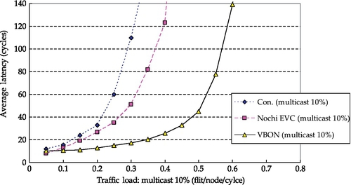
Figure 4.13 shows the performance results when 10% of packets are multicast ones. In conventional NoCs, the multicast transmission path is defined by the source node. The performance significantly degrades and it saturates at a rate less than 0.3 flits per node per cycle. This is because a few multicast packets can cause a lot of the NoC workload, leading to significant throughput degradation. It can be seen that although the optimized NoC design, NOCHI EVC, alleviates this situation by decreasing the pipelining cycles of the routing path, it does not solve the multicast problem. The VBON design can greatly outperform the NOCHI EVC design for multicast transmission. The support for multicast in the VBON design leads to only a small increase in the average latency. This is because the VB can transmit the message to multiple nodes in a broadcast way. And for each multicast transmission, only a few VB transactions are involved.
4.5.2.2 Hierarchical 8 × 8 VBON
For an 8 × 8 mesh structure, the comparison results for average latencies for unicast communication are shown in Figure 4.14. These results are given with different traffic patterns: uniform random, transpose, complement, and Cauchy patterns. The packet communication in this hierarchical VBON may involve four VB clusters. Compared with a 4 × 4 mesh, the average latency of unicast communications in an 8 × 8 conventional NoC design increases significantly owing to the increased number of transmission hops. In this case, the performance improvement caused by the NOCHI EVC and VBON designs is more obvious. For all traffic patterns, the VBON design also performs better than the NOCHI EVC design, ranging from 8% for uniform random traffic to 19% for complement traffic at a rate of 0.3 flits per node per cycle. This is because the communication of multiple-segment VBs can take less time than that of pipelined EVCs.

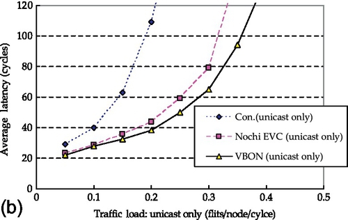


Figure 4.15 shows the comparison results for average latencies for multicast communication. To get an accurate understanding of the performance impact for multicast communications, we provide three different multicast percentages in the whole communication: 5%, 10%, and 20%. Compared with the NOCHI EVC design, the proposed VBON design shows better throughput for all three cases. Furthermore, as the percentage of multicast communication increases, this improvement is more obvious. This demonstrates that the VBON design can scale well for large multicast communication in a hierarchical way.


4.5.3 Real application evaluations
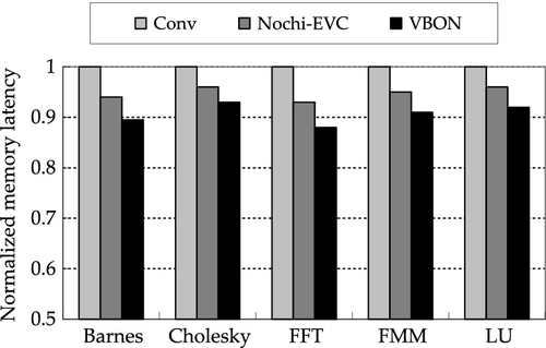
We also ran the application traffic to evaluate the VBON and use memory access latency as the performance metric for various NoC designs. Figures 4.16 and 4.17 illustrate the comparison results for memory latency normalized to that of the baseline NoC design for 4 × 4 mesh and 8 × 8 mesh structures respectively. We see that the VBON has the best overall performance for memory access. It outperforms the baseline and NOCHI EVC designs by 4.3% and 9.3% respectively in an 8 × 8 mesh structure. This performance improvement is mainly because the benchmarks have many long-latency and multicasting packets for maintaining the cache coherency. The results of application executions have demonstrated the effectiveness of the VBON design.

4.5.4 Power consumption analysis
Figure 4.18 shows the power consumption of the NoC designs. The power consumption results were obtained by executing application traffic in an 8 × 8 mesh topology. As the figure indicates, the conventional NoC design has the largest power consumption, and is used as the baseline design. The NOCHI EVC design reduces the power consumption by an average of about 14%. This is mainly due to a reduction in buffer and crossbar power consumption in bypassing routers. In a similar way, the proposed VBON design can also reduce the power consumption by about 20%. In summary, the proposed VBON design clearly outperforms the other two NoC designs across all benchmarks not only in performance but also in power consumption.

4.5.5 Overhead analysis
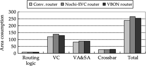
In this subsection, we analyze the overhead introduced by the VBON design from performance and area aspects. On one hand, the integration of the VB mechanism into the NoC design will pause the original point-to-point transmissions when their links are right on the VB path. This may introduce latency overheads for these paused packet transmissions. On the other hand, the VB mechanism can reduce the latency of critical transmissions, including multicast and long-latency packet transmissions. This will result in overall performance improvement as shown in the previous evaluation.
The modifications of conventional routers in the VBON will also introduce some area overheads. In order to estimate the hardware cost, we implemented the conventional NoC router, the NOCHI EVC router, and the VBON router in Verilog and performed the logic synthesis using Synopsys Design Compiler to get the area information. We used a Taiwan Semiconductor Manufacturing Company 90 nm CMOS generic process technology in logic synthesis. The area of the control network (with the bus arbiter and control wires) can be ignored compared with the area of the 128-bit-wide routers and 128-bit bidirectional links of the NoC network. In addition to the control network, the impacts of the proposed router microarchitecture modifications are illustrated in Figure 4.19. From the figure, about 6% area overhead for VBON is observed. This is due to the added logic, such as the pause logic, VC control logic for the VB, and some buffers to store the information on existing router states. The NOCHI EVC router has a higher area overhead, about 10% compared with the conventional router. This is mainly because the number of buffers added in VC logic is large.
To get resource consumption information that is relevant to the CMOS library, we also provide the gate number results. The total number of gate equivalents for the conventional router is about 28,000, while for the VBON router it is about 31,000. The NOCHI EVC router has the highest gate number, about 32,800.
4.6 Chapter summary
In this chapter, the VBON, a hybrid architecture with a packet-based NoC and a transaction-based VB, has been proposed. The point-to-point links of conventional NoC designs can be used as bus transaction links dynamically for VB requests. To reduce the latency of the physical layout for the bus organization, we used several buses instead of one bus to limit the longest distance of the network to a bearable bound. Furthermore, the hierarchical clustered bus structure was configured, dividing the chip into several clusters of cores with redundant bus structures connecting routers in each cluster. Detailed experimental results confirmed that the VBON can achieve low latency while sustaining high throughput for both unicast and multicast communications at low cost.