A single-cycle router with wing channels†
Abstract
With increasing numbers of cores, the communication latency of networks-on-chip becomes a dominant problem owing to complex operations per node. In this chapter, we try to reduce the communication latency by proposing a single-cycle router architecture with wing channels, which forward the incoming packets to free ports immediately with the inspection of switch allocation results. In addition, the incoming packets assigned to wing channels can fill in the time slots of the crossbar switch and reduce the contentions with subsequent ones, thereby increasing the throughput effectively. We design the proposed router using a 65 nm CMOS process, and the results show that it supports different routing schemes and outperforms the express virtual channel, prediction, and Kumar’s single-cycle routers in terms of latency and throughput. When compared with the speculative router, it provides a latency reduction of 45.7% and throughput improvement of 14.0%. Moreover, we show that the proposed design incurs a modest area overhead of 8.1%, but the power consumption is reduced by 7.8% owing to fewer arbitration activities.
2.1 Introduction
As semiconductor technology is continually advancing into the nanometer region, a single chip will soon be able to integrate thousands of cores. There is a wide consensus, from both industry and academia, that the many-core chip is the only efficient way to utilize the billions of transistors, and it represents the trend of future processor architectures. Recently, industry and academia have delivered several commercial or prototype many-core chips, such as the Teraflops [5], TILE64 [18], and Kilocore [10] processors. The traditional bus or crossbar interconnection structures encounter several challenges in the many-core era, including the sharply increasing wire delay and the poor scalability. The network-on-chip (NoC), as an effective way for on-chip communication, has introduced a packet-switched fabric to address the challenges of the increasing interconnection complexity [1].
Although the NoC provides a preferable solution to mitigate the long wire delay problem compared with the traditional structures, the communication latency is still a dominant challenge with increasing core counts. For example, the average communication latencies of the 80-core Teraflops and 64-core TILE64 processors are close to 41 and 31 cycles, since their packets being forwarded between cores must undergo complex operations at each hop through five-stage or four-stage routers. The mean minimal path of an n × n mesh is given by the formula 2n/3 − 1/3n [20]; the communication latency increases linearly with the expansion of the network size. In this way, the communication latency easily becomes the bottleneck of application performance for the many-core chips.
There has been significant research to reduce the NoC communication latency via several approaches, such as designing novel topologies and developing fast routers. Bourduas and Zilic [2] proposed a hybrid topology which combines the mesh and hierarchical ring to provide fewer transfer cycles. In theory, architects prefer to adopt high-radix topologies to further reduce average hop counts; however, for complex structures such as a flattened butterfly [6], finding the efficient wiring layout during the back-end design flows is a challenge in its own right.
Recently, many aggressive router architectures with single-cycle hop latencies have been developed. Kumar et al. [8] proposed the express virtual channel (EVC) to reduce the communication latency by bypassing intermediate routers in a completely nonspeculative fashion. This method efficiently closes the gap between speculative routers and ideal routers; however, it does not work well at some nonintermediate nodes and is suitable only for deterministic routing. Moreover, it sends a starvation token upstream every fixed n cycles to stop the EVC flits to prevent the normal flits of high-load nodes from being starved. This starvation prevention scheme results in many packets at the EVC source node having to be forwarded via a normal virtual channel (VC), which increases average latencies.
Another predictive switching scheme is proposed in Refs. [14, 16], where the incoming packets are transferred without waiting for the routing computation (RC) and switch allocation (SA) if the prediction hits. Matsutani et al. [11] analyzed the prediction rates of six algorithms, and found that the average hit rate of the best one was only 70% under different traffic patterns. This means that many packets still require at least three cycles to go through a router when the prediction misses or several packets conflict. Kumar et al. [7] presented a single-cycle router pipeline which uses advanced bundles to remove the control setup overhead. However, their proposed design works well only at a low traffic rate since it emphasizes that no flit exists in the input buffer when the advanced bundle arrives. Finally, the preferred path design [12] is also prespecified to offer the ideal latency, but it cannot adapt to the different network environments.
In addition to the single-cycle transfer property exhibited by some of the techniques mentioned above, we emphasize three other important properties for the design of an efficient low-latency router:
(1) A preferred technique that accelerates a specific traffic pattern should also work well for other patterns and it would be best to be suitable for different routing schemes, including both deterministic and adaptive ones.
(2) In addition to low latencies under light network loads, high throughput and low latencies under different loads are also important since the traffic rate is easily changed on an NoC.
(3) Some complex hardware mechanisms should be avoided to realize the cost-efficiency of our design, and these mechanisms include the prediction, speculation, retransmission, and abort detection logics.
To achieve these three desired properties, we propose a novel low-latency router architecture with wing channels in Section 2.2. Regardless of what the traffic rate is, the proposed router inspects the SA results, and then selects some new packets without port conflicts to enter into the wing channel and fill the time slots of crossbar ports, thereby bypassing the complex two-stage allocations and directly forwarding the incoming packets downstream in the next cycle. Here, no matter what the traffic pattern or routing scheme is, once there is no port conflict, the new packet at the current router can be delivered within one cycle, which is the optimal case in our opinion. Moreover, as the packets of the wing channel make full use of the crossbar time slots and reduce contentions with subsequent packets, the network throughput is also increased effectively.
We then modify a traditional router with few additional costs, and present the detailed microarchitecture and circuit schematics of our proposed router in Section 2.3. In Section 2.4 we estimate the timing and power consumption using commercial tools, and evaluate the network performance via a cycle-accurate simulator considering different routing schemes under various traffic rates or patterns. Our experimental results show that the proposed router outperforms the EVC router, the prediction, and Kumar's single-cycle router in terms of latency and throughput metrics. Compared with the state-of-the-art speculative router, our proposed router provides latency reduction of 45.7% and throughput improvement of 14.0% on average. The evaluation results for the proposed router also show that although the router area is increased by 8.1%, its average power consumption is reduced by 7.8% owing to fewer arbitration activities at low rates. Finally, Section 2.5 concludes this chapter.
2.2 The router architecture
This section proposes the single-cycle router architecture which supports several different routing schemes. On the basis of the inspection of SA results, the proposed router selects the incoming packets forwarded to the free ports for immediate transfers at wing channels without waiting for their VC arbitration (VA) and SA operations. Hence, it can reduce the communication latency and improve the network throughput under various environments. On the basis of the analysis of a baseline NoC router, we first present the single-cycle router architecture and its pipeline structure in Section 2.2.1. Then, we explain the detailed design of the wing channel in Section 2.2.2.
2.2.1 The overall architecture
It is well known that wormhole flow control was first introduced to improve performance through fine-grained buffering at the flit level. Here, the router with a single channel, playing a crucial role in the implementation of cost-efficient on-chip interconnects, always supports low latency owing to its low hardware complexity. However, it is prone to head-of-line blocking, which is a significant performance-limiting factor.
To remedy this predicament, the VC provides an alternative to improve the performance, but it is not amenable to cost-efficient on-chip implementation. Some complex mechanisms, including the VA and the two-phase SA, increase the normal pipeline stage. By detailed analysis of a router with VCs, it can be found that the SA and switch traversal (ST) are necessary during the transfer of each packet, but the pipeline delay of the former always exceeds that of the latter [17]. Hence, we believe that the complex two-phase SA may be preferred because of the arbitration among multiple packets at high rates, but it would increase communication latencies at low rates, where the redundant arbitrations, which increase the pipeline delay, are unwanted since no contention happens.
Given the aforementioned analysis, we introduce another alternative to optimize the single-cycle router. When an input port receives a packet, it computes the state of the forwarding path on the basis of the output direction and SA results. If the forwarding path is free, this port grants the wing channel to the packet, and then bypasses the two-phase SA pipeline stage to forward the packet directly. For the purpose of illustration, we first introduce the original speculative router [17] and then describe the detailed modifications.
The main components of a speculative router include the input buffers and next routing computation (NRC), VA, SA, and crossbar units. When a header flit comes into the input channel, the router at the first pipeline stage parallelizes the NRC, VA, and SA using speculative allocation, which performs SA based on the prediction of the VA winner. When the VA operation fails owing to conflicts with other packets, the router cancels the SA operation regardless of its results. Then, at the second pipeline stage, the winning packets will be transferred through the crossbar to the output port.
Figure 2.1 illustrates our proposed low-latency router architecture modified on the basis of the speculative router mentioned above. First, each input port is configured with a single wing channel, which uses the same number of flit slots to replace any VC reference, thus keeping the buffering overhead the same. The function of the wing channel is to hold the packets without contentions with others and to assert the request signal to a fast arbiter immediately when packets arrive to implement the single-cycle transfer. Note that since the packet transfer at wing channels is established with the SA results from the previous cycle, it has lower priority than the normal transfers. Second, we add the fast arbiter, which is of low complexity, to handle the requests from wing channels of all inputs. Here, the winner of fast arbitration will now progress to crossbar traversal.
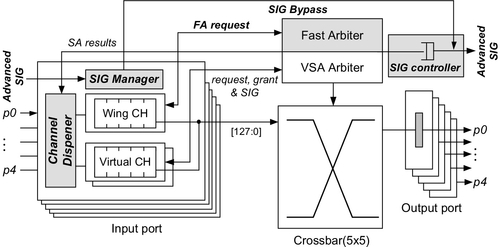
Third, each input introduces a channel dispenser unit. In contrast to the original router, the proposed router allocates the logical identifier of the free channel in the neighborhood. According to the logical identifier stored in the header flits, the dispenser unit grants the physical channel identifier to new packets. Besides, this unit is also responsible for selecting proper packets to use the wing channel, which is described in detail in Section 2.2.2. Finally, we use the advanced request signal to perform the RC in advance. In the original router, the RC or NRC must be completed before the ST, and it is difficult to combine them [13] in a single cycle without harming the frequency. Here, the advantage of the proposed advanced RC method is to decouple the routing and switch functions by precomputing the routing information before a packet arrives. As shown in Figure 2.1, because the signal manager has already received the request signal from the signal controller of the upstream neighborhood, the incoming packets can directly enter the ST stage without RCs being repeated.
Figure 2.2 depicts the original and proposed aggressive pipelines on which a header flit is transferred from router 0 to router 2. Here, the header flit in the original router requires at least two consecutive cycles to go through the VC and switch allocation (VSA)/NRC and ST pipeline stages. But in our proposed router, since the routing information is prepared prior to the arrival of the packet, the header flit can go through the crossbar switch within a single cycle once its input and output ports are both free. In the scenario shown in Figure 2.2, the flit arriving at router 0 inspects the contentions with other packets and then it selects the normal VC to be forwarded to the right output through the original two-stage pipeline.
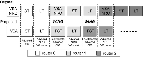
Here, once the header flit succeeds in winning the VC arbitration, it will send an advanced request signal (SIG) downstream in the next cycle for the routing precomputation at the downstream neighborhood. Then, the header flit is able to bypass the pipeline at router 1 by directly entering the wing channel on its arrival since its forwarding path is inspected to be free. In the previous link traversal (LT) pipeline stage, router 1 has generated a VC mask to determine the candidates for each output port among all the competing wing channels. In the fast switch transfer (FST) stage, router 1 chooses the single winning header flit to be transferred through the crossbar switch according to VC masks and propagates its advanced SIG downstream to router 2. At router 2, the header flit transfer is also completed in a single cycle, similarly to that at router 1.
For the purpose of comparison, Figure 2.3 illustrates the packet transfers of each input for a certain period when they are deployed with the original and proposed routers respectively. The x axis denotes the time, the y axis denotes the input port, the white boxes are the transfers at the wing channel, and the gray boxes are the transfers at normal VCs. At the beginning, while the packet addressed from input 4 to output 2 is blocked owing to the contention, other packets from inputs 1 and 3 are delivered toward outputs 2 and 4 respectively. In this scenario, we collect all the time slots of the crossbar switch, and it can be seen that, as compared with the original router (Figure 2.3a), the proposed router provides up to 45.1% reduction in latency and up to 31.7% improvement in throughput; these gains are mainly due to the single-cycle transfers and decreased contentions.

On the basis of a detailed analysis of the router behaviors, the proposed router obviously outperforms the original router, and the reasons for this are as follows. First, with the inspection of the SA results in the previous cycle, the proposed router allocates the free time slots of the crossbar switch for single-cycle transfers of new packets at wing channels. It can reduce the packet latencies and improve the SA efficiency, thereby increasing throughput. Second, the single-cycle transfers of new packets at wing channels advance all the packets at the same input and significantly reduce the level of contentions with subsequent packets of other inputs, which translates directly to a higher throughput.
Next, we provide two case studies. The first case happens at cycle 4, where the packets from inputs 2, 3, and 4 rush to output 4 simultaneously. In the original router, the SA chooses only a single winner, and thus it leads to the idle cycles of inputs 3 and 4 as shown in Figure 2.3a. But wing channels are granted to these packets in our proposed router. At cycle 5, when the packet from the normal channel of input 4 is forwarded toward output 2, the new packet at input 2 undergoes the single-cycle transfer with wing channels immediately once it inspects the idle state of output 4, thereby improving the switch channel utilization. Next, let us consider the second case, where the new packet arrives at input 4 at cycle 2. Here, the packet in the original router is delivered to output 3 one cycle later than in our proposed router, and thus it directly suspends the transfers of subsequent packets forwarded to output 2 or output 4. As illustrated in Figure 2.3a, the contentions at output 2 or output 4 become higher after cycle 7 than in our proposed router, and this is mainly attributed to competition among these suspended packets and competition from other inputs.
2.2.2 Wing channels
This section describes several principles of the wing channel for the single-cycle transfer as follows:
• The dispensation of the wing channel. When the header flit is transferred to the input, it is granted the wing channel if both its input and its output are inspected to be free. In this case, the header flit will transfer through the crossbar in a single cycle without competition for network resources.
• The allocation of the VC. To support the single-cycle transfers in the proposed router, a wing channel should be granted higher priority over normal channels to win the output VC. But if multiple wing channels of different inputs are competing for the same direction, the router will use a simple and practical VC mask mechanism to cancel most of the VC requests, producing only a single winner for one output at each cycle.
• The arbitration of the crossbar switch. The new packet at the wing channel sends its request to the fast arbiter (FSA) unit if its output VC has been granted or its VC mask is invalid. If it wins the fast arbitration, the header flit will be delivered to the right output and its body flits will come into heel in sequence. In this scenario, the transfer requests from normal channels of the same input will be cancelled until the wing channel becomes empty, or the tail of the packet leaves the router. However, if its fast arbitration fails, an idle cycle of the input port is inevitable and then the flits of other normal channels will go through the switch in the next cycle depending on the current SA results.
• The transmission of an advanced SIG. The SIG encodes the logical identifier of the channel, NRC results, and destination node. For an 8 × 8 mesh, this wiring overhead is 10 bits, around 7.8% of the forward wiring, assuming 16-byte-wide links. In the proposed router, if the VC mask of the new packet at the wing channel is invalid, its advanced SIG must be given the highest priority to be forwarded downstream immediately. However, for those packets with valid VC masks or at normal channels, their advanced SIGs are sent to the SIG FIFO unit one cycle later than the grant of output VCs. Obviously, the latter has lower priority than the former. With this principle, we ensure that the completion of the RC is prior to the arrival of the packet, because the advanced SIG always arrives at least one cycle earlier than header flits.
Next, Figure 2.4 shows a timing diagram for packet transfer from router 1 to router 5 with these principles. At cycle t2, the header flit arriving at router 2 enters the wing channel by inspecting the SA results, and then it transfers through the router and forwards its advanced SIG in the next cycle. When the header reaches router 3, its RC is already completed. But at cycle t4, this flit cannot be delivered immediately owing to its contentions with the packets of other wing channels. Here, the router sets up the VC mask and repeats the request of the output VC at [t4, t5]. Once the VA has been won at cycle t5, the router immediately sends the advanced SIG to the FIFO unit and this flit's trip continues through the FST stage at the same time. Note that although the header flit stays at router 3 for more than one cycle, it allows the packets of other channels to be transferred in advance without affecting the network performance. Finally, owing to the contentions inspected at cycle t7, this header flit selects the normal channel and transfers through the original pipeline stage, thereby leaving the wing channel to subsequent new packets.

On the basis of the above principles, the fast arbitration unit allocates the free time slots of the crossbar switch to new packets when they arrive to improve the network performance and reduce the power consumption. Figure 2.5 illustrates the effect of fast arbitration for the wing channel. At cycle 4, the transfer completion of the wing channel informs the normal channels at the same input to request their outputs. The packets that win the SA are then able to traverse the crossbar and leave no idle cycle on the input link of the switch, which translates directly to a higher throughput. Next, at cycle 8, the empty slot due to the SA failure of cycle 7 is filled by the single-cycle transfer of fast arbitration, which also leads to a significant improvement in throughput. However, the idle cycle of the input link still appears at cycle 10. Here, our proposed router restarts the output requests of the other channels at the same port when it inspects the empty wing channel FIFO unit owing to the transfer interrupt, and thus leaves one idle cycle. This scenario is unavoidable but there is no serious performance degradation because of its low frequency. On the other hand, our proposed router cancels the output requests of other channels during the transfer of the wing channel, which can decrease the arbitration power consumption in most cases.

2.3 Microarchitecture designs
On the basis of an original speculative router, this section presents the main microarchitecture designs, including the channel dispenser, fast arbitration, SIG controller, and SIG manager units.
2.3.1 Channel dispensers
Figure 2.6 shows the microarchitecture of the channel dispenser, which is mainly composed of the VC assigner, VC tracker, and VC table. The VC table forms the core of the dispenser logic. It is a compact table indexed by the logical channel ID, and holds the physical channel ID and tail pointers at each entry. With the VC table, the VC tracker simply provides the next available channels by keeping track of all the normal ones.
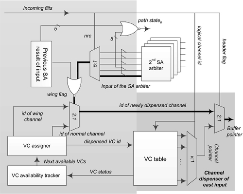
When receiving the information from the VC tracker, the VC assigner decides whether to grant a wing channel or a normal channel to the new packet on the basis of the generated wing flag. Once any channel has been granted to the incoming packets, the VC assigner needs to provide the dispensed channel ID to the VC table to change the status of the available channels. Here, the VC assigner is also responsible for improving the throughput by fully utilizing all VCs at high rates. When all the normal VCs at the local input are exhausted, the VC assigner is forced to allocate the wing channel to the new packet. In this way, when the normal VCs are occupied and the generated wing flag is false, the wing channel will serve as a normal one, and the packet allocated the wing channel will apply for the channel and switch like those in the normal ones. Our experiments described in Section 2.4.3 validate the effectiveness of this technique under different routing schemes.
This channel dispenser also guarantees protocol- and network-level deadlock-free operations by adopting relatively low-cost methods. Toward that goal, we use different VC sets for request and response message types, respectively, to avoid protocol- and network-level deadlock situations. The proposed router includes two VC sets per port: the first VC set is composed of channel 0 (i.e., wing channel), channel 1, and channel 2, and is used by the request packets; the second VC set, comprising channels 0, 1, and 3, is used by the response packets.
Note that since channels 2 and 3 are used by request and response packets exclusively, we can provide deadlock-free operations in two aspects. First, in order to provide deadlock recovery in adaptive routing algorithms, channels 2 and 3 employ a deterministic routing algorithm to break the network deadlock. For any packet at the wing channel or channel 1, once it has been checked for possible deadlock situations, the channel dispenser unit of the neighborhood will grant channels 2 and 3 to this packet with higher priority, thereby using deterministic routing to break the network deadlock situation. Second, we introduce separate channels 2 and 3 for two different message types to break the dependencies between the request and response messages. When both the shared channel 0 and channel 1 at the neighborhood are holding other messages of different types, the current message can be transferred through the exclusive VC on the basis of its own type, thereby breaking the dependency cycle between messages of different classes.
To satisfy the tight timing constraint, the real-time generation of a wing flag is very important, as shown in Figure 2.6, where we adopt a favorable tradeoff between the limited timing overhead and the fast packet transfer. In the dispenser unit, the inputs of the second-phase switch arbitration are used to inspect the output state of the next cycle; however, the inspection of the input state using the results of the original SA pipeline would prove to be intolerable because it influences seriously the timing of the critical path. Instead, we consider the previous outputs of the SA to be the default input state, thereby reducing the critical path. In such a scenario, the winning request from the SA of the current cycle influences the single-cycle transfer of wing channels but does not harm the network performance at high loads, since the winning packet will be transferred in the next cycle. As illustrated in Figure 2.6, the nrc information from the header flit controls the multiplexer (MUX) to select the inputs of the second-phase switch arbitration on the basis of its output direction. Only when both the MUX output and the previous output of the SA are false is the wing channel granted to the new packets.
Using the technology-independent model proposed by Peh and Dally [17], we compare the delay of channel dispensation indicated by the thick line with that between the input of the second-phase switch arbitration and VSA stage results, as shown below:
In the typical case of five ports and four channels, the former equation equals 9.3 fan-outs of 4 (FO4), which is close to the 9.9 FO4 of the latter one. In addition, it also introduces some timing overheads to generate the buffer pointer based on the LTs. With the same model, a delay of 3 FO4 is added when compared with the v-input MUX of the original router. Here, the delay of 1 mm wire after placement and routing in a 65 nm process is calculated be 8.2 FO4, which is far less than the 18 FO4 of the original critical path. Hence, this overhead would not harm the network frequency.
2.3.2 Fast arbiter components
Taking the east port as an example, we show in Figure 2.7 the microarchitecture of a fast arbiter which includes the VC mask logic in the upper left corner and the transfer arbitration logic in lower right corner. First, the grant bit for the wing channel of a certain input is set in the case when the incoming header tends to undergo the single-cycle transfer from this input to output east as discussed in Section 2.2.1. In order to do so, the incoming header always needs to check the states of the wing channel and its forwarding path as shown in Figure 2.7. Then, on the basis of these grant bits for the wing channels, the VC mask logic shields multiple requests competing for the same output. Here, the state indicating that one input request has priority over another is stored in a matrix, which is updated each cycle in a round-robin fashion to reflect the new priorities. With the current matrix state, the mask bit of an input is set when any input request that has higher priority is asserted. Finally, this logic will assert the new request of a wing channel to compete for the output if the conditions of the grant bit and the VC mask bit are both satisfied. In our design, any valid bit of the wing grant register also generates a request mask signal to shield input requests of all the first-phase VC arbiters for a particular output, thereby reducing the energy overhead of VC arbitration.

The packets at the wing channels undergo single-cycle transfers based on the fast arbitration results, and thus the delay of the functions on the entire path through the VC mask register, fast arbiter, and crossbar traversal is calculated in Equation (2.3), where the result of 14.3 FO4 in the case of five ports and 16-byte width (w = 128) is lower than the 18 FO4 of the original critical path:
In addition, with the same model, the timing overhead of the wing grant and VC mask based on the LT is calculated to be about 4.0 FO4, which also has no influence on the critical path.
2.3.3 SIG managers and SIG controllers
Figure 2.8 shows the SIG manager of the input port and the SIG controller of the output port. Here, the SIG manager completes the RC in the next cycle of advanced SIG arrivals, and records the results in a compact SIG table, which holds the transfer destination and NRC information. For the incoming packet, the header flit uses its logical channel identifier to select and latch its SIG information on the basis of the SIG input table. By receiving SIGs from multiple inputs, the SIG controller decides on the winning SIG according to the new request from the wing channel in the next cycle. On the other hand, for the other packets at normal channels or blocked ones at wing channels, the two-phase VC arbitration logic provides their advanced SIG instead. For the purposes of low complexity, our proposed router adopts another two-phase VC arbitration [15], where the first-phase arbiters at each input gain winner requests from different directions and then the second-phase logic at each output generates a final winner at each cycle. With the winner of the first phase, the SIG selection, which is parallel with second-phase arbitration, is performed by the MUX. Then, according to the second-phase result, the SIG controller selects the SIG of final winners, thereby forwarding it to the SIG FIFO unit in the next cycle.

2.4 Experimental results
2.4.1 Simulation infrastructures
In this section, we present the simulation-based performance evaluation of the proposed router in terms of latency, throughput, pipeline delay, area, and power consumption, under different traffic patterns. To model the network performance, we develop a cycle-accurate simulator, which models all major router components at the clock granularity, including VCs, switch allocators, and flow controls. The simulator inputs are configurable, allowing us to specify parameters such as the network size, routing algorithm, channel width, and VC counts. And the simulator also supports various traffic patterns, such as random, hotspot, and nearest-neighbor patterns. Here, all simulations are performed in an 8 × 8 mesh network by simulating 8 × 10⁵ cycles for different rates after a warm-up phase of 2 × 10⁵ cycles. In more detail, each router is configured with five physical channels, including the local channel, and each port has a set of four VCs with a depth of four 128-bit flits. To take the estimation a step further for the original and proposed routers, we firstly synthesize their RTL designs with a 65 nm standard cell library by Synopsys Design Compiler, and then derive the pipeline delay with static timing analysis by Synopsys Timing Analyzer. For power consumption, we further finish the physical design of the above-described on-chip network and antimark the parasitic parameters derived from the circuit layout into netlist to evaluate the total power overhead. In this way, the switching activities of both routers and wires were captured through gate-level simulation using a core voltage of 1.2 V and a frequency of 500 MHz.
2.4.2 Pipeline delay analysis
Figure 2.9 displays the distribution of the pipeline delay obtained by varying the numbers of ports and channels for two routers. It is evident that the wing channel incurs a modest timing overhead for the ST and LT stages, but this does not obviously affect the delay of the VSA stage, which is the critical path in our design. Here, with the number of ports and channels increasing to a certain extent, the difference of their critical path delay is quite small.
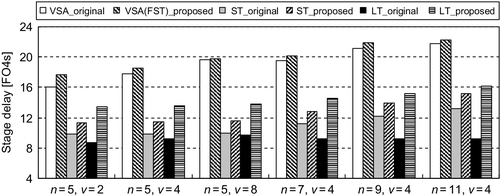
As shown in Figure 2.9, the critical path delay of the proposed router is increased by 8.9% in the case of five ports and two channels, but this difference is gradually reduced to 3.2% and 1.3% when the number of channels reaches four and eight respectively. This is because the delay between the input of the second-phase switch arbitration and the VSA stage results increases as the channel number (i.e., v) increases, while that of channel dispensation is constant. Then, in the case of four channels, it can be seen that the critical path delay of our router tracks that of the original one well, and this is because the change of t2(n, v) is close to that of t1(n) as n increases. As expected, the path through the fast arbiter and crossbar traversal has never been the critical one with increasing n in our timing analysis, and this proves that our proposed router is suitable for different port numbers without obvious frequency degradation. As shown, the increase of the critical path delay is around 3.7% on average in different cases.
2.4.3 Latency and throughput
This section first compares three routers in terms of zero-load latency as shown in Figure 2.10. With increasing network size, the proposed router is clearly much more efficient at reducing the latency. The results show that the proposed router reduces the zero-load latency by 34.3% compared with the original one when the network size reaches 16-ary. Then, it also results in 22.6% and 16.1% reductions in average zero-load latency over prediction [11] and EVC [8] routers with different network sizes.

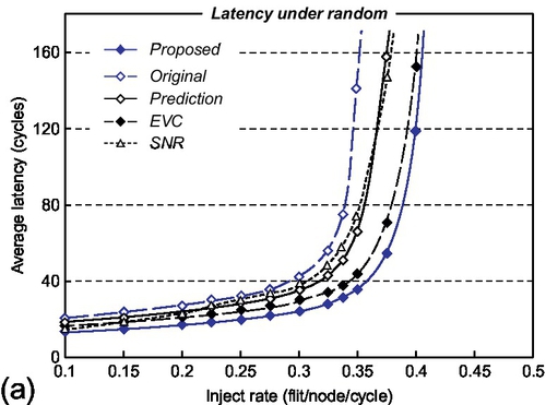
Next, we evaluate the network performance of the proposed router as a function of the injection rate and traffic pattern under different routing schemes, and compare it with those of the original router, prediction router [11], EVC router [8], and Kumar's single-cycle router [7] respectively. Here, we refer to Kumar's single-cycle router as SNR for simplicity, and all the prediction, EVC, and SNR structures are implemented and incorporated into our cycle-accurate simulator. To study the performance of EVCs, we configure one EVC within the entire set of four VCs and consider the dynamic EVC scheme with a maximum EVC length of three hops. For better performance of the prediction router, we use many 4-bit binary counters to construct the history table, which records the number of references toward all the outputs, and thus the router can achieve a higher hit rate by supporting the finite context prediction method. Finally, for a fair comparison, we use the statically managed buffers in SNR and assign the same number of buffers to each VC per port when modeling the behavior of major components.
Figure 2.11 displays the network performance of four routers under XY deterministic routing. For a random traffic pattern (Figure 2.11a), the proposed router latency of 13.1 cycles at a rate of 0.1 flits per node per cycle is closer to the ideal, e.g., 11.8 cycles, when compared with the 20.3,18.6,16.5, and 13.8 cycles of the others. Here, our proposed router performs single-cycle transfer at each node at a low rate; however, the prediction router always takes three cycles when the prediction misses and the EVC router still needs two cycles at some nonintermediate nodes along its express path. Then, with the increase of network loads, our proposed router uses the single-cycle transfer of the wing channel to fill in the free time slot of the crossbar switch and reduce the contentions with subsequent packets of other inputs, thereby leading to significant improvement of throughput. However, with increase of network traffic, the SNR's performance, which is almost identical to that of our proposed router at low rates, begins to degrade obviously. This is attributed to its strict precondition that no flit exists in the input buffer when the advanced bundle arrives. Under higher traffic rates, with SNR it is hard to forward most incoming packets within one cycle owing to there being many residual flits at router input ports. The results for our proposed router show 44.5%, 34.2%, 21.7%, and 36.1% reductions in average latency compared with the other four routers, while improving throughput by 17.1%, 9.3%, and 9.0% over the original, prediction, and SNR routers respectively.
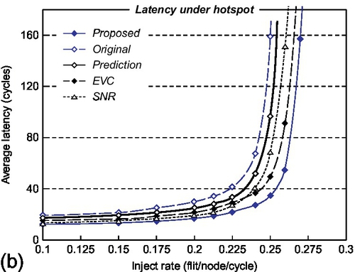
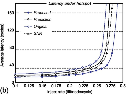
For the hotspot pattern (Figure 2.11b), the wing channel is effective in reducing packet latency at many low-load nodes, while improving switch throughput by shortening service time and reducing residual packets at a few high-load nodes. Hence, the simulation results show that our proposed router reduces average latency by 46.8%, 38.8%, and 25.1% and improves throughput by 10.8%, 8.2%, and 4.1% when compared with the original, prediction, and SNR routers respectively. Then, we observe that the express channels at some low-load nodes are underutilized. Because the EVC router prevents EVC flits periodically to avoid the starvation of normal flits, many packets at low-load nodes cannot be forwarded through express channels that are occupied by others, thereby increasing packet latencies. As shown in Figure 2.11b, our proposed router reduces the average latency by 27.8% when compared with the EVC router.
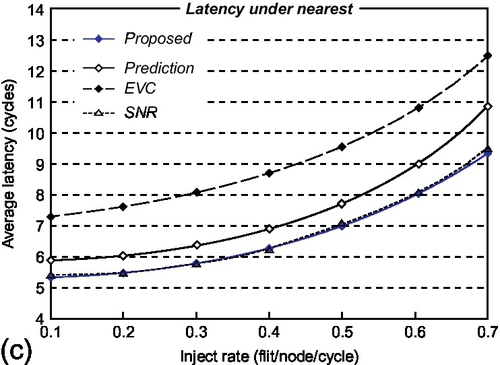
For the nearest-neighbor pattern, the EVC router does not work well, and takes two cycles at each node for communications between neighborhoods. Then, the prediction router performs the single-cycle transfer at the neighbor but still needs three cycles at the source node when the prediction misses. In contrast, our proposed router and the SNR router perform better than the others, as shown in Figure 2.11c. This is because their packets can transfer through either the source or the destination in a single cycle. As shown in Figure 2.11c, the latency of our router is reduced by 27.0% and 10.2% when compared with the EVC and prediction routers respectively.
In addition, Figure 2.12 compares network performance under regional congestion awareness adaptive routing among all routers except the EVC router, which is restricted to the deterministic routing scheme. Here, we use the combinations of free VCs and crossbar demand to be the congestion metric [4]. First, the proposed router outperforms the original and SNR routers in terms of packet latency and saturated throughput in all cases. For the SNR router, the adaptive routing algorithm forwarding packets to the low traffic load regions reduces the possibility of contention, and thus helps in clearing the input buffers by delivering the incoming flits in time. As seen in Figure 2.12a and b, at low injection rates, the performance of the SNR router tracks that of the proposed router well. However, as network traffic increases, the increasing number of residual flits per port starts to cancel the single-cycle pipeline operations at the SNR router. Note that this issue can be completely avoided in our proposed design by guaranteeing fast transferring of the wing channel. It can be seen that our design outperforms the SNR router, with the latency reduction near saturation being nearly 44.2%. Second, for the prediction router, the latest port matching strategy to predict output is introduced to provide high hit rates in most cases, but only approximately 68% of predictions hit in our experiment. Once the prediction misses or the packet conflicts, it requires at least three cycles in contrast with two cycles for our proposed router to forward a header flit, thereby increasing the number of residual packets and saturating network throughput in advance. When compared with the prediction router, our results in Figure 2.12a and b show that average latency is reduced by 28.1% and 34.0% and network throughput is improved by 10.2% and 5.6% for random and hotspot patterns respectively.


Finally, we also investigate the performance of the proposed router under realistic network traces which are collected from the 64-processor multiprocessor simulator [3] using the raytrace and barnes applications from SPLASH2 benchmarks [19]. Figure 2.12c illustrates the simulation results for three different routers when compared with the original router under adaptive routing. For the raytrace application, the communication patterns among nodes correspond to low traffic load with large hop counts. In this case, the switch contention is low and the router ports are empty, and thus one-cycle delays through the SNR and proposed routers are realized, whereas the prediction router needs three cycles when the predictions miss according to the traffic patterns or history tables. It can be seen that the SNR router and the proposed router provide up to 32.1% and 32.3% reductions in average latencies, in contrast with that for the prediction router, which is 19.4%. Then, for the barnes application, representing a moderate traffic rate with fewer hop counts, the multiple flits stored in the input buffer seriously influence the one-cycle transferring process through the SNR router. In contrast, our proposed router enables the single-cycle pipeline operations if only its delivering input and output ports are inspected to be free, regardless of how many flits are stored in the input buffers. Hence, the evaluation results in Figure 2.12c show that with the barnes trace, our proposed router, with a latency reduction of 28.6%, outperforms the SNR router, with the reduction in this case being around 19.3%.
2.4.4 Area and power consumption
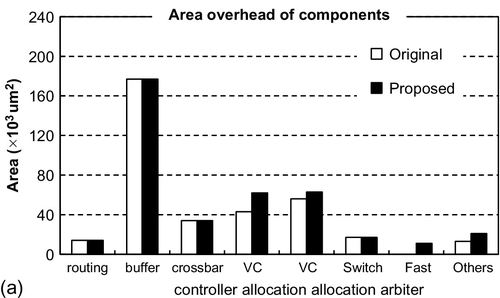
This section estimates the area of the original and proposed routers with a 65 nm standard cell library as shown in Figure 2.13a. Here, both of them are configured with 16 buffers per input port, and thus the wing channel will not incur any extra area overhead due to buffer resources. In our proposed router, we add the channel dispenser, the SIG manager, and the fast arbiter, and modify the VC arbitration component. However, the area overhead of these components contributes little to the total area, which is dominated by the buffers. Thus, the total area of our router is increased by nearly 8.1% compared with that of the original router.
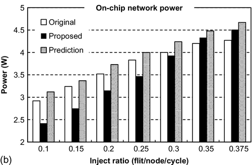
In terms of power consumption, we investigate 8 × 8 mesh networks with adaptive routing at different rates in Figure 2.13b. Here, because the increasing number of wires incurs some extra link power as reported in Section 2.2.2, both routers and forward wires are considered in the power evaluation on the basis of the physical design of an on-chip network. Although more switching activities of the channel dispensation, SIG forwarding, and transmission lead to a modest increase of power consumption, the average power consumption of the proposed router when compared with the original one is still reduced by 7.8%. This is because most packets which undergo the single-cycle transfer at low rates avoid the complex two-stage switch and VC arbitration activities. For the prediction router, the high miss rate always results in the frequent switching activities of some complex logics, e.g., abort detection, copy retransmission, and flit killer, which are power consuming and completely avoided in our design. Hence, it can be seen that the power consumption of the proposed router is lower than that of the prediction router at all rates, with an average reduction of 15.1%.
2.5 Chapter summary
As continuing shrinkage of technology in the nanometer era is leading to an increase in the number of cores, the NoC as an effective communication fabric will face the tough challenges of low latency and high throughput in the future. In this chapter, we proposed a practical router architecture with a wing channel, which is granted to the incoming packets by inspecting SA results for the single-cycle transfers. With the wing channel, the packet transfers also improve the SA efficiency and reduce contentions with subsequent ones from other ports, thereby increasing throughput effectively. The proposed router is designed using a 65 nm CMOS process, and it only incurs little overhead of critical path delay while exhibiting excellent scalability with increasing numbers of channels and ports. Simulation results using a cycle-accurate simulator indicate that our proposed design outperforms the EVC, prediction, and SNR routers in terms of latency and throughput under various traffic patterns, and it provides 45.7% latency reduction and 14.0% throughput improvement as compared with the speculative router. Moreover, although the router area is increased by 8.1%, the average power consumption is reduced by 7.8%, which is attributed to fewer arbitration activities at low rates.