Supporting cache-coherent collective communications†
Abstract
Across many architectures and parallel programming paradigms, collective communication plays a key role in performance and correctness. Hardware support is necessary to prevent important collective communication from becoming a system bottleneck. Support for multicast communication in networks-on-chip has achieved substantial throughput improvements and power savings. In this chapter, we explore support for reduction or many-to-one communication operations. As a case study, we focus on acknowledgement messages (ACK) that must be collected in a directory protocol before a cache line may be upgraded to or installed in the modified state. This chapter makes two primary contributions: an efficient framework to support the reduction of ACK packets and a novel balanced, adaptive multicast routing algorithm. The proposed message combination framework complements several multicast algorithms. By combining ACK packets during transmission, this framework not only reduces packet latency by 14.1% for low-to-medium network loads, but also improves the network saturation throughput by 9.6% with little overhead. The balanced buffer resource configuration of balanced, adaptive multicast improves the saturation throughput by an additional 13.8%. For the PARSEC benchmarks, our design offers an average speedup of 12.7% and a maximal speedup of 16.8%.
8.1 Introduction
Efficient and scalable on-chip communication will be required to realize the performance potential of many-core architectures. To harness this performance, it is imperative that networks-on-chip (NoCs) be designed to efficiently handle a variety of communication primitives. Collective communication lies on the critical path for many applications; the criticality of such communication is evident in the dedicated collective and barrier networks employed in several supercomputers, such as the NYU Ultracomputer [15], CM-5 [25], Cray T3D [2], Blue Gene/L [3], and TianHe-1A [45]. Likewise, many-core architectures will benefit from hardware support for collective communications but may not be able to afford separate, dedicated networks owing to rigid power and area budgets [36]; this chapter explores integrating collective communication support directly into the existing NoC.
Various parallel applications and programming paradigms require collective communication such as broadcast, multicast, and reduction. For example, a directory-based coherence protocol relies heavily on multicasts to invalidate shared data spread across multiple caches [19] and token coherence uses multicasts to collect tokens [31]. Reductions and multicasts are used for barrier synchronization [37, 44]. These collective communications can have a significant effect on many-core system performance. Without any special hardware mechanisms, even if 1% of injected packets are multicast, there is a sharp drop in saturation throughput [12]. Recent work proposes efficient multicast routing support to improve NoC performance [1, 12, 21, 27, 39–41, 43].
Often, a multicast will trigger an operation, such as invalidating a cache line [19] or counting available tokens [31]. To notify the source of the completion of these operations, the multicast destination nodes send out responses. The resulting many-to-one communication operation is called a reduction [9]. Figure 8.1 shows that a cache line invalidation message triggers on average 7.44 acknowledgment messages (ACKs) for the PARSEC benchmarks [4] in a 16-core system.1

Prior NoC multicast proposals [1, 12, 21, 27, 39–41, 43] implicitly assumed several unicast packets will deliver these messages to a single destination; this can lead to redundant network traversal operations and create transient hotspots inside the network. To provide high performance, scalable NoCs should handle traffic in an intelligent fashion by eliminating these redundant messages.
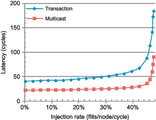
Furthermore, the multicast-reduction transaction cannot be completed until all responses have been received [5, 10, 19, 23, 26, 31]. As a result, the transmission of reduction messages lies on the critical path of a multicast-reduction transaction. These multicast-reduction operations are often associated with stores; for out-of-order cores, stores do not lie on the critical path. However, these stores can delay subsequent loads to hotly contended cache lines. For chip multiprocessors (CMPs) that employ simple, in-order cores, stores will lie on the critical path and can significantly impact performance. Figure 8.2 shows the completion latency of multicast-reduction transactions in a 4 × 4 mesh running uniform random traffic. The transmission of reduction packets accounts for approximately 40% of the total transaction latency. We propose a novel packet reduction mechanism to improve performance of the full multicast-reduction transaction.
A noteworthy property of coherence-based reduction messages is that they carry similar information in a simple format. For example, invalidation ACKs only carry the acknowledgment for each node, and token count replies merely carry the count of available tokens at each node. Therefore, these response messages can be combined without loss of information. Combining these messages eliminates redundant network traversals and optimizes performance. We propose an efficient message combination framework with little overhead. To simplify the discussion, we focus on invalidation ACK packets in a directory-based coherence protocol. Our design can be easily extended to other types of reductions such as those used in token coherence [31].
Our proposed message combination framework complements several multicast routing algorithms. Sending a multicast packet constructs a logical tree in the network. The framework steers each ACK packet to traverse the same logical tree back to the root (source) of the multicast. In each router, a small message combination table (MCT) records total and received ACK counts for active multicast transactions. When an ACK packet arrives at the router, the MCT is checked. If the router has not received all expected ACKs, the table is updated and the incoming ACK is discarded. If the router has received all expected ACKs, the incoming ACK packet is updated and forwarded to the next node in the logical tree. Dropping in-flight ACK packets reduces network load and power consumption.
Our goal is to improve overall network performance in the presence of both unicast and multicast-reduction traffic. The recently proposed recursive partitioning multicast (RPM) routing algorithm utilizes two virtual networks (VNs) to avoid deadlock for multicasts [41]. However, the division of these two VNs results in unbalanced buffer resources between vertical and horizontal dimensions, which negatively affects performance. Therefore, we propose a novel multicast routing algorithm, balanced, adaptive multicast (BAM), which does not need two VNs to avoid multicast deadlock. BAM balances the buffer resources between different dimensions, and achieves efficient bandwidth utilization by computing an output port on the basis of all the multicast destination positions.
To summarize, our main contributions are as follows:
• An efficient message combination framework that reduces latency by 14.1% and the energy-delay product (EDP) by 20-40% for low-to-medium network loads and improves saturation throughput by 9.6%.
• A novel multicast routing algorithm which balances buffer resources across different dimensions and improves network throughput by an additional 13.8%.
8.2 Message combination framework
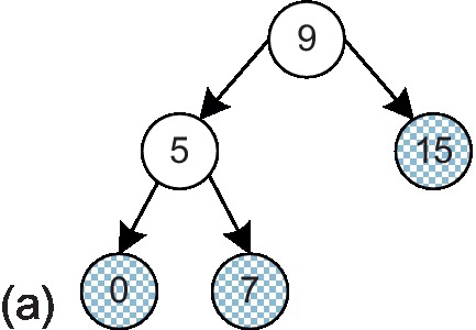
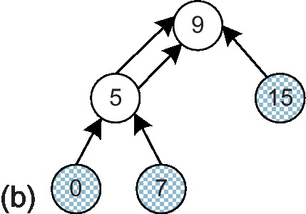
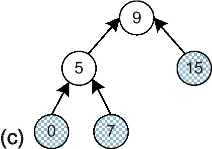
In this section, we describe the proposed message combination framework. We use a multicast-reduction example to illustrate the framework. One multicast packet with destinations 0, 7, and 15 is injected by node 9. A logical multicast tree [13] is built as shown in Figure 8.3a; gray nodes indicate destinations, while white nodes are branches that are only traversed by the packet. Each multicast destination responds with an ACK message to the root node, node 9. Without combination, the ACKs are transmitted as unicast packets back to node 9 (Figure 8.3b).2 These ACK packets traverse some common channels; merging them can reduce the network load. Figure 8.3c shows the logical ACK tree with message combination, which is the same as the logical multicast tree except with the opposite transmission direction. In this example, routers 5 and 9 serve as fork routers which are responsible for gathering and forwarding ACKs. Next, we address two important issues associated with our message combination framework: ensuring that ACK packets traverse the same logical tree as the multicast packet and ensuring that the fork routers are aware of the expected total and currently received ACKs.
In an n × n mesh network, a log (n × n)-bit field in the multicast header is reserved to identify the router where the last replication happened (pre_rep_router). This field is initially set to be the source node and is updated when a multicast packet replicates during transmission. A 3-bit ID field is used to differentiate multicast packets injected by the same source node. This field is incremented when a new multicast packet is injected. The src field encodes the source node.
A small MCT is added to each router. A multicast allocates an MCT entry upon replication. This entry records the identity of the router where the last multicast replication occurred and the total expected ACK count. The transmission of a multicast packet establishes a logical tree. Each branch in the logical tree has an MCT entry pointing to the previous fork router.
Each multicast destination responds with an ACK packet. A log (n × n) -bit field (cur_dest) in the ACK header serves to identify the intermediate destination. Its value is set to the pre_rep_router field in the triggering multicast packet. Each ACK packet has two fields named multicast_src and multicast_ID, which correspond to src and ID of the triggering multicast packet respectively. An additional log(n × n)-bit field (ACK_count) is used to record the carried ACK response count of the combined packet.
When an ACK packet arrives at its current destination, it accesses the MCT. If the router has not yet received all expected ACKs, the incoming packet is discarded and the entry's received ACK count is incremented. If the router has received all expected ACKs, the incoming ACK packet updates its cur_dest field to be the next replication router. It will be routed to the fork router at the next level; thus, ACK packets traverse the same logical tree as multicast in the opposite direction.
8.2.1 MCT format
Figure 8.4 illustrates the format of an MCT entry. The V field is the valid bit for the entry. The src, ID, and pre_rep_router fields are the same as the corresponding fields in the multicast packet initializing this entry. The MCT is a content-addressable memory (CAM); the src and ID fields work together as the tag. The incoming_port field records the incoming port of the multicast packet. The expected_count field indicates the total expected ACK count, which is equal to the number of destinations at this branch of the multicast tree. The value of the cur_ACK_count field tracks the current received ACK count. As we will show later, recording the total expected ACK count instead of simply counting the number of direct successors is needed for handling full MCTs.

8.2.2 Message combination example
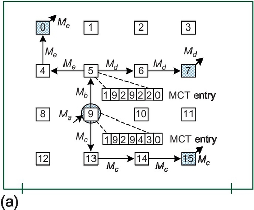
Figure 8.5a gives a multicast example within a 4 × 4 mesh network which is the same as that in Figure 8.3a. Figure 8.5b shows the multicast header values. Although our framework is independent of the multicast packet format, we assume bit string encoding [6] for the destination addresses in the destinations field of the header for clarity. Ma is the injected packet; its destinations field contains the three destinations. Ma replicates into two packets, Mb and Mc, at router 9. An MCT entry is created. The src, ID, and pre_rep_router fields of this entry are fetched from Ma. The incoming_port field is set to 4 to indicate that Ma comes from the local input port. The expected_count field is set to the total destination count of Ma: 3. The cur_ACK_count field is setto 0. At router 5, Mb replicates into two packets: Md and Me. An MCT entry is created with an expected_count of 2. The pre_rep_router fields of both Md and Me are updated to 5 since the last replication occurred at router 5.
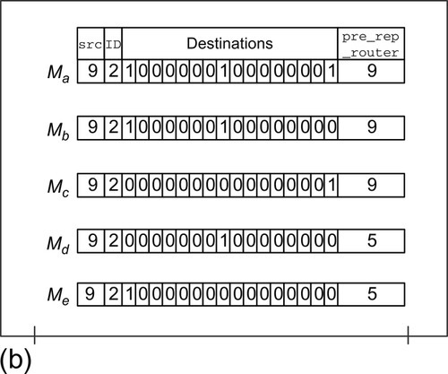
After a destination node receives a multicast, it responds with an ACK packet. Figure 8.6a shows the transmission of ACK packets corresponding to the multicast shown in Figure 8.5a. Figure 8.6b gives the ACK header values.


The Ac, Ad, and Ae packets are triggered by the Mc, Md, and Me multicast packets respectively. The multicast_src, multicast_ID, and cur_dest fields of the ACK packets are equal to the src, ID, and pre_rep_router fields, respectively, of the triggering multicast packet. The ACK_count fields of these three ACK packets are set to 1 since they all carry an ACK response from only one node.
The cur_dest field defines the current destination of the ACK packet. As shown in Figure 8.6a, Ae can be routed along a different path than Me to reach its intermediate destination at router 5. ACK packets need only follow the same logical tree as the multicast packet, giving our design significant flexibility. A similar scenario can be seen for Ac, Ad and Ae both set their cur_dest fields as router 5; at router 5, they will be merged. Analysis shows that the possibility of multiple simultaneous MCT accesses is quite low (0.1% or less) as ACK packets will experience different congestion. A small arbiter is used to serialize concurrent accesses. Assuming Ad arrives earlier than Ae, its multicast_src and multicast_ID are used together as the tag to search the MCT. The sum of the cur_ACK_count field of the matched entry and the carried ACK_count of Ad is 1, which is smaller than the expected_count of 2 in that entry. Therefore, Ad is discarded and the cur_ACK_count field is incremented by 1.
When Ae arrives at router 5, it accesses the MCT. Since router 5 has received all expected ACKs, Ae will remain in the network. Its cur_dest field is updated to the pre_rep_router field of the matched entry and its ACK_count field is updated to 2 since it now carries the ACK responses of nodes 0 and 7 (see Ab). Ab uses the incoming_port field of the matched entry as the output port. The combined ACK packet is required to use the same multicast path for one hop to avoid an additional routing computation (RC) stage, which would add an additional cycle of latency. Now that router 5 has received all expected ACKs, the corresponding MCT entry is freed. Finally, node 9 receives Ab and Ac and combines them into Aa. The multicast-reduction transaction is complete.
8.2.3 Insufficient MCT entries
So far, we have assumed that there is always an available MCT entry when a multicast packet replicates. However, since the table size is finite, we must be able to handle a full MCT. If there are no free MCT entries, the replicated multicast packet will not update its pre_rep_router field. In the previous example, if there is no available MCT entry at router 5 when Mb replicates, Md and Me will keep their pre_rep_router field as 9. When Ad and Ae are injected, their cur_dest fields are set to 9; they will combine in router 9 instead of router 5. Both Ad and Ae must travel to router 9. In this case, router 9 will receive two ACK packets for the northbound replication branch; this is why we record the expected total count of ACKs in the MCT instead of recording the number of direct successors in the logic multicast tree. In our design, insufficient MCT entries may affect performance, but do not pose any correctness issues. We evaluate the effect of the MCT size in Section 8.5.3.
8.3 Bam routing
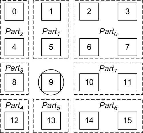
In this section, we describe our BAM routing algorithm. To achieve efficient bandwidth utilization, a multicast routing algorithm must compute the output port on the basis of all destination positions in a network [41]. A simple and efficient routing algorithm, RPM, was recently proposed to deliver high performance [41]. As shown in Figure 8.7, RPM partitions the network into at most eight parts on the basis of the current position, and applies several priority rules to avoid redundant replication for destinations located in different parts; the goal is to deliver a multicast packet along a common path as far as possible, then replicate and forward each copy on a different channel bound for a unique destination subset.
We observe that although RPM provides efficient bandwidth utilization, it suffers from unbalanced buffer resources between different dimensions, which negatively affects network performance. To avoid deadlock for multicast routing, RPM divides the physical network into two VNs: VN0 is for upward packets and VN1 is for downward ones. The horizontal virtual channel (VC) buffers must be split into two disjoint subsets for the two VNs, while the vertical ones can be exclusively used by one VN [9, 41]. When a packet is routed in each VN, there are 2x more available vertical buffers than horizontal ones. This unbalanced buffer configuration negatively affects both unicast and multicast routing, since the more limited horizontal VCs become a performance bottleneck. Configuring different VC counts for different dimensions may mitigate this effect. However, it requires different control logic for each input port as the size of the arbiters in VCs and switch allocators is related to the VC count; a heterogeneous router requires extra design effort [33]. Also, the critical path may increase since it is determined by the largest arbiter. Therefore, we assume a homogeneous NoC router architecture in this chapter.
On the basis of these observations, we propose a novel adaptive multicast routing algorithm: BAM. The deadlock freedom of BAM is achieved by utilizing Duato's unicast deadlock-avoidance theory [8] for multicast packets, rather than leveraging multiple VNs. The multicast packets in NoCs are generally short as they carry only control packets for the coherence protocol; these are most likely single-flit packets [12], making the routing of each multicast branch independent. Thus, Duato's unicast theory can be applied to multicasts by regarding the routing of each multicast branch as an independent unicast. In Duato's theory, VCs are classified into escape and adaptive VCs. When a packet resides in an adaptive VC, it can be forwarded to any permissible output port. This property enables BAM to select the best output port on the basis of all destination positions. An additional advantage is that this design is compatible with an adaptive unicast routing algorithm.
Figure 8.7 shows the partitioning of destinations into eight parts. For Part1, Part3, Part5, or Part7, there is only one admissible output port. For Part0, Part2, Part4, or Part6, there are two alternative output ports. If a multicast packet has some destinations located in Part1, Part3, Part5, and Part7, the corresponding north, west, south, and east output ports must be used; these ports are called obligatory output ports for this multicast packet. To achieve efficient bandwidth utilization, we design a heuristic output port selection scheme for destinations located in Part0, Part2, Part4, and Part6:
(1) if only one of the two alternative output ports is an obligatory output port for the multicast packet, the router will use this output port to reach the destination;
(2) if the two alternative output ports are both obligatory output ports or are both not obligatory output ports, the router will adaptively select the one with less congestion.
This scheme maximally reuses the obligatory output ports to efficiently utilize bandwidth.
Figure 8.8 shows the output port calculation logic for BAM. The 1-bit Pi indicates whether there is a destination in Parti. Take Part0 as an example: ![]() and
and ![]() indicate that the router uses the north or east port to reach the destinations located in Part0. Nne and Ene signals indicate whether the north or east output has less relative congestion in the northeast quadrant. These signals are provided by the RC module.
indicate that the router uses the north or east port to reach the destinations located in Part0. Nne and Ene signals indicate whether the north or east output has less relative congestion in the northeast quadrant. These signals are provided by the RC module.
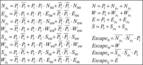
Escapen, Escapew, Escapes, and Escapee indicate whether the multicast packet can use the escape VC for the north, west, south, and east output ports respectively. If a multicast packet uses the north output port to reach nodes in Part0 or Part2, it is not allowed to use the north escape VC since this packet will make a turn forbidden by dimensional order routing (DOR). A similar rule is applied to the south escape VC. The east and west escape VCs are always available for routing. If a multicast packet resides in an escape VC, it will replicate according to DOR, similarly to that in virtual circuit tree multicasting [12]. Once a multicast packet enters an escape VC, it can be forwarded to the destinations using only escape VCs; there is no deadlock among escape VCs. Any multicast packet residing in an adaptive VC has an opportunity to use an escape VC. This design is deadlock-free [8]. Compared with RPM, BAM does not need to partition the physical network into two VNs to avoid multicast deadlock; it achieves balanced buffer resources across vertical and horizontal dimensions. Moreover, BAM achieves efficient bandwidth utilization as well.
8.4 Router pipeline and microarchitecture
Our baseline is a speculative VC router [7, 11, 38]. Lookahead signals transmit the unicast routing information one cycle ahead of the flit traversal to overlap the RC and link traversal (LT) stages [17, 24]. We use a technique to preselect the preferred output for adaptive routing; the optimal output port for each quadrant is selected one cycle ahead on the basis of network status [16, 22, 28]. The pipeline for unicast packets is two cycles plus one cycle for LT, as shown in Figure 8.9a.


Including multicast routing information in the lookahead signals requires too many bits; therefore, we assume a three-cycle router pipeline for multicasts, as shown in Figure 8.9b. A multicast packet replicates inside the router if multiple output ports are needed to reach the multicast destinations. We use asynchronous replication to eliminate lock-step traversal among several branches; the multicast packet is handled as multiple independent unicast packets in the VC allocation (VA) and switch allocation (SA) stage, except that a flit is not removed from the input VC until all requested output ports are satisfied [21, 41].
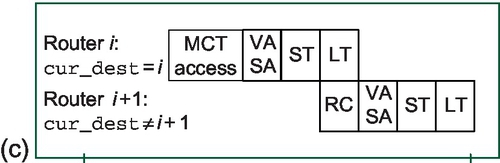
ACK packets are handled differently from other unicast packets. When an ACK packet arrives, its cur_dest field is checked. If this field does not match the current router, the ACK packet is handled like a normal unicast packet (Figure 8.9a). If they match, the ACK packet accesses the MCT instead of performing the RC. The MCT access overlaps with the RC stage. As we show in Section 8.5.3, this operation can fit within a single pipeline stage; it does not add additional latency to the critical path. Figure 8.9c and 8.9d illustrates the ACK packet pipeline.
Figure 8.10 illustrates the proposed router microarchitecture. If a multicast packet needs multiple output ports after the RC, an entry is allocated in the MCT. This operation overlaps with the VA/SA operations and does not add delay to the critical path. The Port Preselection module provides eight signals indicating the optimal output port for each quadrant [16, 22, 28]. These signals are used by both unicasts and multicasts to avoid network congestion.

8.5 Evaluation
We evaluate our message combination framework with RPM and BAM using synthetic traffic and real application workloads. We modify the cycle-accurate BookSim simulator [20] to model the router pipelines and microarchitecture described in Section 8.4. For synthetic traffic, we configure two VNs to avoid protocol-level deadlock [7]: one for multicasts and one for ACKs. RPM further divides the multicast VN into two sub-VNs: one for upward packets and one for downward ones. BAM does not need to sub-divide the multicast VN. Normal unicast packets can use any VN. However, once a packet has been injected into the network, its VN is fixed and cannot change during transmission. Unicast packets are routed by an adaptive routing algorithm. For BAM's multicast, BAM's ACK, and RPM's ACK VNs, the algorithm is designed on the basis of Duato's theory [8] and uses one VC as the escape VC. The two sub-VNs of RPM's multicast VN enable adaptive routing without requiring escape VCs. We use a local selection strategy for adaptive routing: when there are two available output ports, the selection strategy chooses the one with more free buffers.
Multicasts and ACKs are single-flit packets, while the normal unicast packet lengths are bimodally distributed; the unicast packets consist of five-flit packets (50%) and one-flit packets (50%). We use several synthetic unicast traffic patterns [7], including uniform random, transpose, bit rotation, and hotspot, to stress the network for detailed insight. We control the percentage of multicast packets relative to whole injected packets. For multicasts, the destination counts and positions are uniformly distributed. A cache's ACK packet response delay is uniformly distributed between one and four cycles. We assume a 64-entry MCT; in Section 8.5.3, we explore the impact of MCT size. Table 8.1 summarizes the baseline configuration and variations used in the sensitivity studies.
Table 8.1
The Baseline Simulation Configuration and Variations
| Characteristic | Baseline | Variations |
| Topology (mesh) | 4 × 4 | 8 × 8, 16 × 16 |
| VC configuration | 4 flits per VC, 8 VCs per port | 4 and 6 VCs per port |
| Packet length (flits) | Normal, 1 and 5 (bimodal); ACK, 1; multicast, 1 | – |
| Unicast traffic | Uniform random, transpose bit rotation, hotspot | – |
| Multicast ratio | 10% | 5%, 15%, 20% |
| Multicast destination count | 2-10 (uniformly distributed) | 2-4, 4-14, 10-14, 15 |
| ACK response cycles | 1-4 (uniformly distributed) | – |
| MCT entries | 64 | 0, 1, 4, 16 |
| Warm-up and total | 10,000 and 100,000 cycles | – |
To measure full-system performance, we leverage two existing simulation frameworks: FeS2 [35] for x86 simulation and BookSim for NoC simulation. FeS2 is a timing-first, multiprocessor x86 simulator, implemented as a module for Virtutech Simics [30]. We run the PARSEC benchmarks [4] with 16 threads on a 16-core chip multiprocessor consisting of an Intel Pentium 4-like CPU. We assume cores optimized for clock frequency; they are clocked five times faster than the network. We use a distributed, directory-based MOESI coherence protocol that needs four VNs for protocol-level deadlock freedom. The cache line invalidation packets (multicasts) are routed in VN1, while the ACK packets are routed in VN2. The number of VCs per VN, VC depth, and MCT size are the same as the baseline (Table 8.1). Cache lines are 64 bytes wide and the network flit width is 16 bytes. All benchmarks use the simsmall input sets to reduce simulation time. The total run time is used as the metric for full-system performance. Table 8.2 gives the system configuration.
Table 8.2
The Full System Simulation Configuration
| Parameter | Value |
| No. of cores | 16 |
| L1 cache (D and I) | Private, 4-way, 32 kB each |
| L2 cache | Private, 8-way, 512 kB each |
| Cache coherence | MOESI distributed directory |
| Topology | 4 × 4 mesh |
L1, first level; L2, second level.
8.5.1 Performance
We evaluate four scenarios: RPM without message combination (RPM + NonCom), RPM with message combination (RPM + Com), BAM without message combination (BAM + NonCom), and BAM with message combination (BAM + Com).
8.5.1.1 Overall network performance
Figure 8.11 illustrates the overall network performance. For both RPM + Com and BAM + Com there are performance improvements compared with RPM + NonCom and BAM+NonCom respectively; not only are the network latencies reduced, but the saturation throughputs3 are also improved. Detailed analysis reveals that the combination framework reduces the average channel traversal count of ACK packets from 4.7 to 2.5, reducing the network operations by approximately 45% for ACKs.


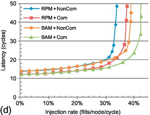
The network latency for RPM + Com is reduced by 10–20% under low-to-medium injection rates4 compared with RPM + NonCom (average 14.1%); larger improvements are seen at high injection rates. Similar latency reductions are seen for BAM + Com versus BAM + NonCom. Packet dropping shortens the average hop distance, resulting in latency reductions at both low and high network loads. The mitigation of ejection-side congestion is also beneficial to latency reduction. Saturation throughput improvements resulting from the framework (RPM + Com vs. RPM + NonCom) range from 8.5% to 11.2% (average 9.6%). There are similar throughput improvements for BAM + Com over BAM + NonCom. Discarding inflight ACKs reduces the network load, which is helpful to improve the saturation throughput.
Across the four patterns, both BAM + NonCom and BAM + Com improve the saturation throughput over RPM + NonCom and RPM + Com respectively. For transpose, bit rotation and hotspot patterns, although BAM + NonCom has larger latencies than RPM + Com under low loads, its saturation throughputs are higher. The balanced buffer configuration between vertical and horizontal dimensions helps BAM to improve the saturation throughput. BAM + Com improves the saturation throughput by 14.2%, 27.6%, 26.4%, and 25.1% (average 23.4%) over RPM + NonCom for the four traffic patterns. Both the ACK packet dropping and the balanced buffer configuration contribute to this performance improvement. As shown in Figure 8.11, the trend between BAM + NonCom and RPM + NonCom is similar to the trend between BAM + Com and RPM + Com; thus, we omit BAM + NonCom in the following sections for brevity.
8.5.1.2 Multicast transaction performance
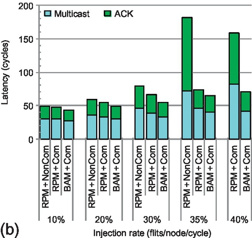
To clearly understand the effects of message combination on multicast transactions, we measure the multicast-reduction transaction latency. Figure 8.12 shows the results for five injection rates. The injection rate for the last group of bars exceeds the saturation point of RPM + NonCom. For all rates, RPM + Com and BAM + Com have lower transaction latencies than RPM + NonCom; dropping ACK packets reduces network congestion and accelerates multicast-reduction transactions. ACK packet acceleration contributes more to the latency reduction than multicasts. A multicast needs to send out multiple replicas; releasing its current VC depends on the worst congestion each replica may face. Thus, the multicast is not as sensitive as the ACK to the network load reduction. For example, with low-to-medium injection rates (0.30 or less) under uniform random traffic (Figure 8.12a), the average multicast delay is reduced by 9.5% for BAM + Com versus RPM + NonCom. Yet, ACK packet delay is reduced by 17.6%. These two factors result in an average transaction latency reduction of 13.4%. The transaction acceleration increases with higher network load. Merging ACKs reduces the number of packets the source needs to wait for to finish a transaction. Waiting for only one ACK instead of multiple ACKs can improve performance since multiple packets may encounter significantly more congestion than a single packet, especially under high network load. For uniform random traffic with a high injection rate (0.40), RPM + Com and BAM + Com reduce the transaction latency by 46.2% and 57.6% respectively compared with RPM + NonCom. The message combination framework accelerates the total transaction by a factor of almost 2. As the injection rate increases, BAM + Com outperforms RPM + Com by a significant margin.


8.5.1.3 Real application performance
Figure 8.13 shows the speedups over RPM + NonCom for the PARSEC benchmarks. Although the message combination framework mainly optimizes the performance for one of the four VNs (the ACK VN) used in full-system simulation, collective communication often lies on the critical path for applications. Also, dropping ACK packets in one VN reduces SA contention and improves the performance of other VNs. These factors result in RPM + Com achieving speedups over RPM + NonCom ranging from 5.3% to 8.3% for all applications. The efficiency of message combination depends on the multicast destination count. The multicast destination counts of bodytrack, facesim, and raytrace are the lowest; the speedups of RPM + Com for these three applications are lower than those for the remaining seven applications.
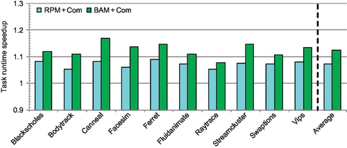
The balanced buffer configuration utilized in BAM + Com supports higher saturation throughput than the unbalanced one. BAM + Com improves the performance of applications which have high network loads and significant bursty communication. For blackscholes, fluidanimate, raytrace, and swaptions, the additional performance gain due to the balanced buffer configuration (BAM + Com vs. RPM + Com) ranges from 2.3% to 3.7%. The network loads of these applications are low and do not stress the network. However, BAM + Com achieves additional speedups ranging from 5.5% to 8.6% over RPM + Com for bodytrack, canneal, facesim, ferret, streamcluster, and vips. These applications have more bursty communication and higher injection rates. For all ten applications, BAM + Com achieves an average speedup of 12.7% over RPM + NonCom. The maximal speedup is 16.8%, for canneal.
8.5.2 Comparing multicast VN configurations
In this section, we delve into the effect of the unbalanced buffer configuration used in the multicast VN of RPM on both unicast and multicast packet routing. Since the ACK VNs of RPM and BAM are the same, we assume the network has only one VN: the multicast VN. Four VCs are configured in this VN, and RPM further divides this VN into two sub-VNs: the horizontal VC count of each sub-VN is two, while the vertical count is four.
8.5.2.1 Unicast performance
Figure 8.14 compares the performance of BAM's and RPM's multicast VN configuration using only unicast packets. To extensively understand the effect of the unbalanced buffer configuration, we evaluate the performance of XY, YX, and a locally adaptive routing algorithm (Adaptive) in RPM's multicast VN. XY efficiently distributes uniform random traffic and achieves the highest performance for this pattern. For the other three patterns, Adaptive has the highest performance; adaptively choosing the output port mitigates the negative effect of unbalanced buffer resources. Therefore, this work uses locally adaptive routing for unicast packets.
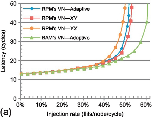


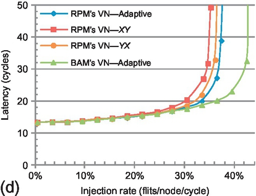
Although Adaptive has better performance than XY and YX, its performance is still limited by the unbalanced buffer resources used in each of RPM's multicast sub-VNs; the horizontal dimension has half the buffer resources of the vertical one. However, in BAM's VN, the numbers of buffers of different dimensions are equal. Adaptive routing in BAM's VN shows substantial performance improvement over Adaptive routing in RPM's VN. Transpose has the largest performance gain, with a 73.2% saturation point improvement. Across these four traffic patterns, BAM's VN-Adaptive achieves an average saturation throughput improvement of 35.3% over RPM's VN-Adaptive.
8.5.2.2 Multicast performance
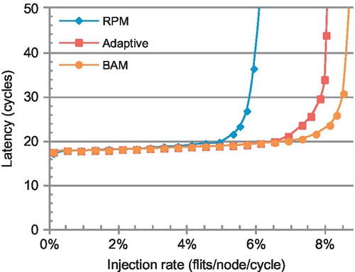
Figure 8.15 shows the performance using 100% multicast packets. The Adaptive curve shows the performance of the adaptive multicast routing algorithm without our heuristic replication scheme; multicast replicas adaptively choose the output ports without considering the reuse of obligatory ports. This negatively affects bandwidth utilization. BAM has 8.7% higher saturation throughput than Adaptive. BAM achieves 47.1% higher saturation throughput over RPM. The effect of the unbalanced buffer resources is greater on multicasts than unicasts. A multicast packet is removed from its current VC only after all its replicas have been sent out; the horizontal VC bottleneck affects multicast performance more strongly than unicast performance. The average switch traversal counts are 8.6, 8.8, and 8.4 for RPM, Adaptive, and BAM respectively, which further demonstrates that our applied heuristic replication scheme achieves efficient bandwidth utilization.
8.5.3 MCT size
As described in Section 8.2.3, the MCT size affects network performance but not correctness. Too few MCT entries will hamper ACK packet combination and force the ACK packets to traverse more hops than with combination. To determine the appropriate size, we simulate an infinite MCT using the baseline configuration (Table 8.1) and uniform random traffic. Multicast packets are routed using BAM. Figure 8.16a presents the maximum and average concurrently valid MCT entries. For low-to-medium injection rates (less than 0.39), the maximum number of concurrently valid entries is less than 10 and the average number is less than 1.5. Even when the network is at saturation (injection rate of 0.52), the maximum number of concurrently valid entries is 49 and the average is 10.15. These experimental results indicate that a small MCT can provide good performance.
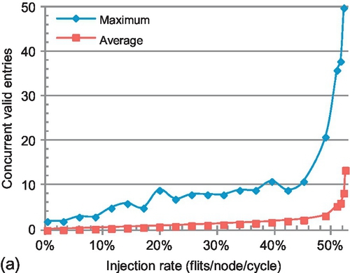
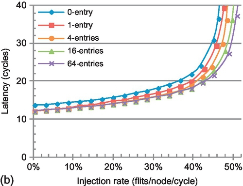
Figure 8.16b shows the performance for different table sizes. The 0-entry curve corresponds to no ACK combination; all ACK packets are injected into the network with their destination set to the source node of the triggering multicast packet. Even with only one entry per router, ACK combination reduces the average network latency by 10%. More entries reduce the latency further, especially for high injection rates. Saturation throughput improvements range from 3.3% to 12.1% for one to 64 entries.
Cacti [34] is used to calculate the power consumption, area, and access latency for the MCT in a 32-nm technology process. Table 8.3 shows the results. If we assume a clock frequency of 1 GHz, a 64-entry table can be accessed in one cycle. This size provides good performance for nearly all injection rates for various traffic patterns. In the full-system evaluation, we observe that the maximal number of concurrently valid entries for the PARSEC benchmarks is less than 25. For area-constrained designs, fewer entries still provide latency and throughput improvements.

8.5.4 Sensitivity to network design
To understand further the scalability and impact of our design, we vary the VC count, multicast ratio, destination count per multicast packet, and network size. Figure 8.17 presents the average performance improvement across the four synthetic unicast traffic patterns. In each group of bars, the first two bars show the saturation throughput improvement, and the second two bars show the latency reduction under low-to-medium loads.
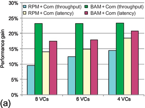


8.5.4.1 VC count
Figure 8.17a shows the performance improvement with eight, six, and four VCs per physical channel. One interesting trend is observed: for smaller VC counts, the gain due to the combination framework increases (RPM + Com vs. RPM + NonCom), while the improvement due to balanced buffer resources declines (BAM + Com vs. RPM + Com). The reasons for this trend are twofold. First, fewer VCs per port makes the VCs a more precious resource; dropping ACK packets improves the reuse of this resource. For example, RPM + Com has 14.8% higher saturation throughput than RPM + NonCom with four VCs per physical channel. As the number of VCs increases, this resource is not as precious; its effect on performance declines. However, even with eight VCs per physical channel, dropping ACK packets still improves the saturation throughput by 9.6%.
Second, BAM + Com uses escape VCs to avoid deadlock. The horizontal escape VC can always be used, while the vertical one can be used only by DOR; there is some imbalance in the utilization of escape VCs, and this imbalance increases with fewer VCs. However, the situation is worse for RPM + Com. In RPM's multicast VN configuration, the vertical dimension always has twice as many VCs as the horizontal one. Even with four VCs per port, the saturation point improvement of BAM + Com is still larger than RPM + Com's improvement by about 9.0%. With fewer VCs, RPM + Com's latency reduction increases; it achieves an 18.5% reduction with four VCs per port. BAM + Com further reduces latency owing to the balanced buffer configuration among different dimensions. The latency difference between BAM + Com and RPM + Com is not as significant as the saturation throughput improvement. Adaptive routing mainly accelerates packet transmission at high injection rates by avoiding network congestion.
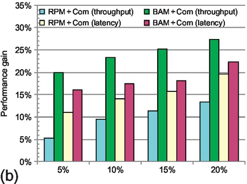
8.5.4.2 Multicast ratio
Figure 8.17b presents the performance improvement for several multicast ratios: 5%, 10%, 15%, and 20%. Increasing the multicast portion leads to greater throughput improvements owing to message combination. The improvement contributed by the balanced buffer configuration remains almost constant (BAM + Com vs. RPM + Com). A higher multicast packet ratio triggers more ACK packets; ACK combination has more opportunity to reduce network load. The framework becomes more effective. BAM + Com achieves a saturation throughput improvement of 27.2% with a multicast ratio of 20%. A higher multicast ratio also results in larger latency reductions. The VC count per physical channel is kept constant (eight VCs per port) in this experiment, so the gap between BAM + Com and RPM + Com remains almost the same.
8.5.4.3 Destinations per multicast
Figure 8.17c illustrates the performance gain for different average numbers of multicast destinations: 3, 6, 9,12, and 15 (broadcast). The trend is similar to varying the multicast ratio. Although the multicast ratio remains constant (10%), more destinations per multicast trigger more ACK packets. The framework combines more of these ACKs during transmission. As the destination count varies from 3 to 15, BAM + Com improves the saturation throughput in the range from 17% to 28%. RPM + Com reduces the latency in the range from 10% to 25%; BAM + Com's latency reduction ranges from 13% to 27%.
8.5.4.4 Network size
Figure 8.17d shows the performance improvement for different network sizes: 4 × 4, 8 × 8, and 16 × 16 mesh networks.5 Since 8 × 8 and 16 × 16 networks have more nodes, we increase the average number of destinations per multicast to 12 and 24 respectively. The message combination framework is more efficient at larger network sizes since packets traverse more hops on average. As a result, combining ACK packets eliminates more network operations. For the 16 × 16 network, the message combination framework improves the saturation point by 16.8%. Similarly, larger network sizes show greater latency reductions. RPM + Com and BAM + Com achieve latency reductions of 25% and 27% respectively for a 16 × 16 mesh. The efficiency of the balanced buffer configuration utilized by BAM + Com remains constant with different network sizes.
Throughout the sensitivity studies, the MCT size is 64 entries. One may think that with more multicast destinations, a higher multicast ratio, or a larger network size that more entries will be required. Yet, analysis reveals changing these aspects reduces the injection rate at which the network becomes saturated. Thus, the maximal concurrently active multicast transactions supported by the network is reduced. As a result, a 64-entry MCT is able to achieve high performance for these different network design points.
8.6 Power analysis
An NoC power model [32] is leveraged to determine overall network power consumption; network power consumption is contributed by three main components: channels, input buffers, and router control logic. The activity of these components is obtained from BookSim. Leakage power is included for buffers and channels. The power consumption of an MCT access is also integrated into the power model. We assume a 128-bit flit width. The technology process is 32 nm and the network clock is 1 GHz on the basis of a conservative assumption of router frequency. Figure 8.18a and 8.18b shows the power consumption using transpose traffic for unicast messages. We measure the MCT access power and the static and dynamic network power for two multicast ratios: 10% and 20%.


The MCT access power comprises only a small portion of the total power. The reason is twofold. The MCT is very small; each entry is only 3 bytes. With 64 entries, the size of the MCT is 192 bytes, which is only 7.5% of the size of flit buffers. Second and more importantly, the MCT access activity is very low. Even when the network is saturated, only 7.2% of all cycles have an MCT access; if the network is not saturated, the activity is even lower.
RPM + Com reduces power consumption compared with RPM + NonCom for all injection rates owing to the dropping of ACK packets. BAM + Com further reduces the power consumption owing to more balanced buffer utilization among different dimensions. As the injection rate increases, the reduction in power consumption becomes more obvious. For an injection rate of 0.35 with a multicast ratio of 10%, RPM + Com and BAM + Com achieve power reductions of 7.6% and 10.8% respectively over RPM + NonCom. With larger multicast ratios, the combination framework is able to reduce power consumption more for both RPM + Com and BAM + Com.
The EDP [14] of the whole network further highlights the energy efficiency of our design, as shown in Figure 8.18c and 8.18d. Dropping ACK packets during transmission not only results in fewer network operations, but also reduces network latency. For low-to-medium injection rates with a multicast ratio of 10%%, RPM + Com and BAM + Com show EDP reductions of about 20–40%. At a high injection rate (0.35), this reduction can be as much as 60–75%. Higher multicast ratios result in greater EDP reduction.
8.7 Related work
In this section, we review related work for message combination and NoC multicast routing.
8.7.1 Message combination
Barrier synchronization is an important class of collective communication, in which a reduction operation is executed first, followed by a broadcast. Gathering and broadcasting worms have been proposed [37]. Many supercomputers, including the NYU Ultracomputer [15], CM-5 [25], Cray T3D [2], Blue Gene/L [3], and TianHe-1A [45], utilize dedicated or optimized networks to support the combination of barrier information. Oh et al. [36] observed that the use of a dedicated network in a many-core platform is unfavorable and proposed the use of on-chip transmission lines to support multiple fast barriers. Our work focuses on collective communication that is used in cache coherence protocols where the multicast is sent first, followed by the collection of ACKs. Bolotin et al. [5] acknowledged that ACK combination might be useful, but did not give a detailed design or evaluation. Krishna et al. [23] proposed efficient support for collective communications in coherence traffic. Our message combination mechanism is quite different from their design. We utilize a CAM to record the ACK arrival information, while they keep the earlier-arriving ACK in network VCs to merge with later-arriving ones [23].
8.7.2 NoC multicast routing
Recent work explores various NoC multicast routing algorithms. Lu et al. [27] used path-based multicast routing, which requires path setup and ACKs, resulting in a long latency overhead. Tree-based multicast mechanisms in NoCs avoid this latency overhead. Virtual circuit tree multicasting [12] is based on the concept of virtual multicast trees. The bLBDR design [39] uses broadcasting in a small region to implement multicasting. RPM [41] focuses on achieving bandwidth-efficient multicasting. On the basis of the isolation mechanism proposed in bLBDR, Wang et al. [43] extended RPM for irregular regions. MRR [1] is an adaptive multicast routing algorithm based on the rotary router. Whirl [23] provides efficient support for broadcasts and dense multicasts. The deadlock avoidance mechanisms of Whirl and our proposed BAM are similar; both are based on Duato's theory [8]. Both BAM and RPM use bit string encoding for multicast packet destinations; this method is not scalable for large networks. Some compression methods [42] can improve the scalability of this encoding scheme. In addition, coarse bit vectors [18], similar to what has been proposed for directories, are another possible approach to reduce the size of the destination set encodings. This type of encoding will increase the number of destinations per multicast and receive greater benefits from our proposal. Delving into this issue is left as future work.
8.8 Chapter summary
Scalable NoCs must handle traffic in an intelligent fashion; to improve performance and reduce power they must eliminate unnecessary or redundant messages. The proposed message combination framework does just that by combining in-flight ACK responses to multicast requests. A small 64-entry CAM is added to each router to coordinate combination. In addition to the framework, we propose a novel multicast routing algorithm that balances buffer resources between different dimensions to improve performance. Simulation results show that our message combination framework not only reduces latency by 14.1% for low-to-medium network loads, but also improves the saturation point by 9.6%. The framework is more efficient for fewer VCs, larger network size, a higher multicast ratio, or more destinations per multicast. The balanced buffer configuration achieves an additional 13.8%% saturation throughput improvement. Our proposed message combination framework can be easily extended to support the reduction operations in token coherence and other parallel architectures.