Chapter 10. RSTP and EtherChannel Configuration
This chapter covers the following exam topics:
2.0 Network Access
2.4 Configure and verify (Layer 2/Layer 3) EtherChannel (LACP)
2.5 Describe the need for and basic operations of Rapid PVST+ Spanning Tree Protocol and identify basic operations
2.5.a Root port, root bridge (primary/secondary), and other port names
2.5.b Port states (forwarding/blocking)
2.5.c PortFast benefits
This chapter shows how to configure Rapid Spanning Tree Protocol (RSTP) and Layer 2 EtherChannels. The EtherChannel content, in the second major section of the chapter, follows a typical flow for most configuration/verification topics in a certification guide: it reviews concepts, shows configurations, and provides show commands that point out the configuration settings and operational state. The details include how to manually configure a channel, how to cause a switch to dynamically create a channel, and how EtherChannel load distribution works.
The first section of the chapter explores RSTP implementation taking a different approach. Cisco mentions RSTP concepts, but not configuration/verification, in the CCNA exam topics. However, to get a real sense of RSTP concepts, especially some concepts specific to Cisco Catalyst switches, you need to work with RSTP configuration and verification. The first section of the chapter explores RSTP implementation, but as a means to the end of more fully understanding RSTP concepts.
For those of you who, like me, probably would want to go ahead and practice configuring RSTP, do some show commands, and understand more fully, you do have some options:
Read Appendix O, “Spanning Tree Protocol Implementation,” from this book’s companion website. The appendix is a chapter from the previous edition of this book, with full details of configuration/verification of STP and RSTP.
Use the STP/RSTP config labs on my blog site (as regularly listed in the Chapter Review section of each chapter).
“Do I Know This Already?” Quiz
Take the quiz (either here or use the PTP software) if you want to use the score to help you decide how much time to spend on this chapter. The letter answers are listed at the bottom of the page following the quiz. Appendix C, found both at the end of the book as well as on the companion website, includes both the answers and explanations. You can also find both answers and explanations in the PTP testing software.
Table 10-1 “Do I Know This Already?” Foundation Topics Section-to-Question Mapping
Foundation Topics Section |
Questions |
|---|---|
Understanding RSTP Through Configuration |
1–3 |
Implementing EtherChannel |
4–6 |
1. Which type value on the spanning-tree mode type global command enables the use of RSTP?
a. rapid-pvst
b. pvst
c. rstp
d. rpvst
2. Examine the following output from the show spanning-tree vlan 5 command, which describes a root switch in a LAN. Which answers accurately describe facts related to the root’s bridge ID?
SW1# show spanning-tree vlan 5

VLAN0005
   Spanning tree enabled protocol rstp
   Root ID  Priority    32773
            Address     1833.9d7b.0e80
            Cost        15
            Port        25 (GigabitEthernet0/1)
            Hello Time  2 sec Max Age 20 sec Forward Delay 15 sec
a. The system ID extension value, in decimal, is 5.
b. The root’s configured priority value is 32773.
c. The root’s configured priority value is 32768.
d. The system ID extension value, in hexadecimal, is 1833.9d7b.0e80.
3. With the Cisco RPVST+, which of the following action(s) does a switch take to identify which VLAN is described by a BPDU? (Choose three answers.)
a. Adds a VLAN tag when forwarding a BPDU on trunks
b. Adds the VLAN ID in an extra TLV in the BPDU
c. Lists the VLAN ID as the middle 12 bits of the System ID field of the BPDU
d. Lists the VLAN ID in the System ID Extension field of the BPDU
4. An engineer configures a switch to put interfaces G0/1 and G0/2 into the same Layer 2 EtherChannel. Which of the following terms is used in the configuration commands?
a. EtherChannel
b. PortChannel
c. Ethernet-Channel
d. Channel-group
5. Which combinations of keywords on the channel-group interface subcommand on two neighboring switches will cause the switches to use LACP and attempt to add the link to the EtherChannel? (Choose two answers.)
a. desirable and active
b. passive and active
c. active and auto
d. active and active
6. A Cisco Catalyst switch needs to send frames over a Layer 2 EtherChannel. Which answer best describes how the switch balances the traffic over the four active links in the channel?
a. Breaks each frame into fragments of approximately one-fourth of the original frame, sending one fragment over each link
b. Sends the entire frame over one link, alternating links in sequence for each successive frame
c. Sends the entire frame over one link, choosing the link by applying some math to fields in each frame’s headers
d. Sends the entire frame over one link, using the link with the lowest percent utilization as the next link to use
Answers to the “Do I Know This Already?” quiz:
1 A
2 A, C
3 A, B, D
4 D
5 B, D
6 C
Foundation Topics
Understanding RSTP Through Configuration
Cisco IOS switches today typically default to using RSTP rather than STP, with default settings so that RSTP works with no configuration. You can buy some Cisco switches and connect them with Ethernet cables in a redundant topology, and RSTP will ensure that frames do not loop. And even if some switches use RSTP and some use STP, the switches can interoperate and still build a working spanning tree—and you never even have to think about changing any settings!
Although RSTP works without any configuration, most medium-size to large-size campus LANs benefit from some STP configuration. For instance, Figure 10-1 shows a typical LAN design model, with two distribution layer switches (D1 and D2). The design may have dozens of access layer switches that connect to end users; the figure shows just three access switches (A1, A2, and A3). For a variety of reasons, most network engineers make the distribution layer switches be the root.
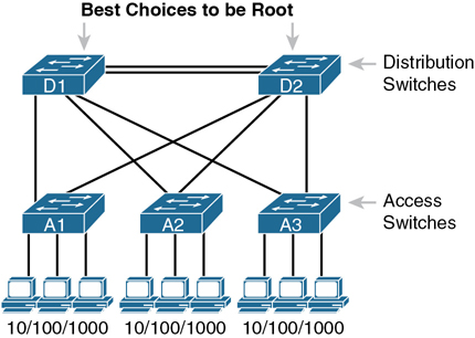
Figure 10-1 Typical Configuration Choice: Making Distribution Switch Be Root
Note
Cisco uses the term access switch to refer to switches used to connect to endpoint devices. The term distribution switch refers to switches that do not connect to endpoints but rather connect to each access switch, providing a means to distribute frames throughout the LAN. If you want to read more about LAN design concepts and terms, refer to this book’s companion website for Appendix K, “Analyzing Ethernet LAN Designs.”
As discussed in the introduction to this chapter, this first section of the chapter examines a variety of STP/RSTP configuration topics, but with a goal of revealing a few more details about how STP and RSTP operate. Following this opening section about RSTP configuration, the next section examines how to configure Layer 2 EtherChannels, and how that impacts STP/RSTP.
The Need for Multiple Spanning Trees
The IEEE first standardized STP as the IEEE 802.1D standard, first published back in 1990. To put some perspective on that date, Cisco did not have a LAN switch product line at the time, and virtual LANs did not exist yet. Instead of multiple VLANs in a physical Ethernet LAN, the physical Ethernet LAN existed as one single broadcast domain, with one instance of STP.
By the mid 1990s, VLANs had appeared on the scene, along with LAN switches. The emergence of VLANs posed a challenge for STP—the only type of STP available at the time—because STP defined a single common spanning tree (CST) topology for the entire LAN. The IEEE needed an option to create multiple spanning trees so that traffic could be balanced across the available links, as shown in Figure 10-2. With two different STP instances, SW3 could block on a different interface in each VLAN, as shown in the figure.
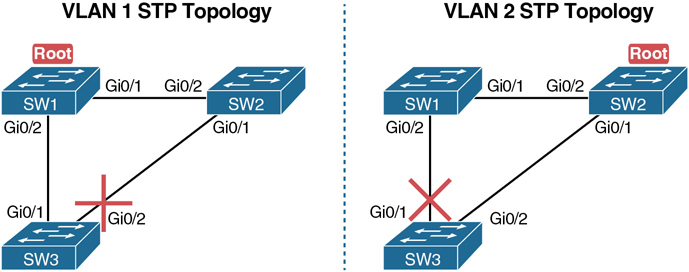
Figure 10-2 Load Balancing with One Tree for VLAN 1 and Another for VLAN 2
STP Modes and Standards
Because of the sequence of events over the history of the various STP family of protocols, vendors like Cisco needed to create their own proprietary features to create the per-VLAN spanning tree concept shown in Figure 10-2. That sequence resulted in the following:
When STP was the only STP standard back in the 1990s with 802.1D, Cisco created the STP-based Per VLAN Spanning Tree Plus (PVST+) protocol, which creates one spanning tree instance per VLAN.
When the IEEE introduced RSTP (in 802.1D amendment 802.1w, in the year 2001), Cisco also created the Rapid PVST+ (RPVST+) protocol. RPVST+ provided more features than standardized RSTP, including one tree per VLAN.
The IEEE did not adopt Cisco’s PVST+ or RPVST+ into their standards to create multiple spanning trees. Instead, the IEEE created a different method: Multiple Spanning Tree Protocol (MSTP), originally defined in 802.1Q amendment 802.1s.
Figure 10-3 shows the features as a timeline for perspective.
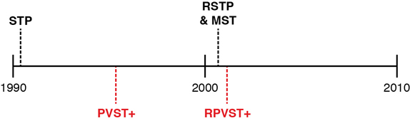
Figure 10-3 Timeline of Per-VLAN and Multiple STP Features
Today, Cisco Catalyst switches give us three options to configure on the spanning-tree mode command, which tells the switch which type of STP to use. Note that the switches do not support STP or RSTP with the single tree (CST). They can use either the Cisco-proprietary and STP-based PVST+, Cisco-proprietary and RSTP-based RPVST+, or the IEEE standard MSTP. Table 10-2 summarizes some of the facts about these standards and options, along with the keywords used on the spanning-tree mode global configuration command. Example 10-1, which follows, shows the command options in global configuration mode.

Table 10-2 STP Standards and Configuration Options
Name |
Based on STP or RSTP? |
# Trees |
Original IEEE Standard |
Config Parameter |
|---|---|---|---|---|
STP |
STP |
1 (CST) |
802.1D |
N/A |
PVST+ |
STP |
1/VLAN |
802.1D |
pvst |
RSTP |
RSTP |
1 (CST) |
802.1w |
N/A |
Rapid PVST+ |
RSTP |
1/VLAN |
802.1w |
rapid-pvst |
MSTP |
RSTP |
1 or more* |
802.1s |
mst |
* MSTP allows the definition of as many instances (multiple spanning tree instances, or MSTIs) as chosen by the network designer but does not require one per VLAN.
Example 10-1 STP Status with Default STP Parameters on SW1 and SW2
SW1(config)# spanning-tree mode ?
  mst         Multiple spanning tree mode
  pvst        Per-Vlan spanning tree mode
  rapid-pvst  Per-Vlan rapid spanning tree mode
SW1(config)#
The Bridge ID and System ID Extension
To support the idea of multiple spanning trees, whether one per VLAN or simply multiple as created with MSTP, the protocols must consider the VLANs and VLAN trunking. (That’s one reason why RSTP and MSTP now exist as part of the 802.1Q standard, which defines VLANs and VLAN trunking.) To help make that work, the IEEE redefined the format of the original BID value to help make per-VLAN instances of STP/RSTP become a reality.
Originally, a switch’s BID was formed by combining the switch’s 2-byte priority and its 6-byte MAC address. The revised rules divide the original priority field into two separate fields, as shown in Figure 10-4: a 4-bit priority field and a 12-bit subfield called the system ID extension (which represents the VLAN ID).
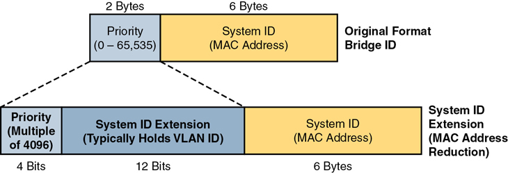
Figure 10-4 STP System ID Extension
Cisco switches let you configure the BID, but only the priority part. The switch fills in its universal (burned-in) MAC address as the system ID. It also plugs in the VLAN ID of a VLAN in the 12-bit system ID extension field; you cannot change that behavior either. The only part configurable by the network engineer is the 4-bit priority field.
However, configuring the number to put in the priority field may be one of the strangest things to configure on a Cisco router or switch. As shown at the top of Figure 10-4, the priority field was originally a 16-bit number, which represented a decimal number from 0 to 65,535. Because of that history, the configuration command (spanning-tree vlan vlan-id priority x) requires a decimal number between 0 and 65,535. But not just any number in that range will suffice; it must be a multiple of 4096, as emphasized in the help text shown in Example 10-2.
Example 10-2 Help Shows Requirements for Using Increments of 4096 for Priority
SW1(config)# spanning-tree vlan 1 priority ?
  <0-61440>  bridge priority in increments of 4096
SW1(config)#
Table 10-3 lists all the configurable values for the STP/RSTP priority. However, do not worry about memorizing the values. Instead, the table lists the values to emphasize two points about the binary values: the first 4 bits in each value differ, but the last 12 bits remain as 12 binary zeros.
Table 10-3 STP/RSTP Configurable Priority Values
Decimal Value |
16-bit Binary Equivalent |
Decimal Value |
16-bit Binary Equivalent |
|---|---|---|---|
0 |
0000 0000 0000 0000 |
32768 |
1000 0000 0000 0000 |
4096 |
0001 0000 0000 0000 |
36864 |
1001 0000 0000 0000 |
8192 |
0010 0000 0000 0000 |
40960 |
1010 0000 0000 0000 |
12288 |
0011 0000 0000 0000 |
45056 |
1011 0000 0000 0000 |
16384 |
0100 0000 0000 0000 |
49152 |
1100 0000 0000 0000 |
20480 |
0101 0000 0000 0000 |
53248 |
1101 0000 0000 0000 |
24576 |
0110 0000 0000 0000 |
57344 |
1110 0000 0000 0000 |
28672 |
0111 0000 0000 0000 |
61440 |
1111 0000 0000 0000 |
Note that while you can set the priority to any of the 16 decimal values in Table 10-3, Cisco provides a convenient means to create a primary and secondary root switch concept without configuring an actual number. In most LAN designs, only a small number of switches would be good candidates to ever be the root switch based on where the switches sit within the topology. Think of the preferred switch as the primary switch and the next-best option as the secondary switch. Then, to configure those two switches to be the two most likely switches to be the root switch, simply configure
spanning-tree vlan x root primary (on the switch that should be primary)
spanning-tree vlan x root secondary (on the switch that should be secondary)
These two commands cause the switch to make a choice of priority value but then store the chosen priority value in the spanning-tree vlan x priority value command. The command with root primary or root secondary does not appear in the configuration. When configuring root primary, the switch looks at the priority of the current root switch and chooses either (a) 24,576 or (b) 4096 less than the current root’s priority (if the current root’s priority is 24,576 or less) to the configuration instead. When configuring, root secondary always results in that switch using a priority of 28,672, with the assumption that the value will be less than other switches that use the default of 32,768, and higher than any switch configured as root primary.
How Switches Use the Priority and System ID Extension
Cisco Catalyst switches configure the priority value using a number that represents a 16-bit value; however, the system ID extension exists as the low-order 12 bits of that same number. This next topic works through connecting those ideas.
When the switch builds its BID to use for RSTP in a VLAN, it must combine the configured priority with the VLAN ID of that VLAN. Interestingly, the configured priority results in a 16-bit priority that always ends with 12 binary 0s. That fact makes the process of combining values to create the BID a little simpler for the switch and possibly a little simpler for network engineers once you understand it all.
First, consider the process shown in Figure 10-5. The top shows the configured priority value (decimal 32768), in 16-bit binary form, with a System ID Extension of 12 zeros. Moving down the figure, you see the binary version of a VLAN ID (decimal 9). At the last step, the switch replaces those last 12 bits of the System ID Extension with the value that matches the VLAN ID and uses that value as the first 16 bits of the BID.

Figure 10-5 Configured Priority (16-Bit) and System ID Extension (12-Bit) Added
As it turns out, the process shown in Figure 10-5 is just the sum of the two numbers—both in binary and decimal. To see an example, refer to upcoming Example 10-3, which demonstrates the following details:
The output shows details about VLAN 9.
The root switch has been configured with the spanning-tree vlan 9 priority 24576 command.
The local switch (the switch on which the command was gathered) has been configured with the spanning-tree vlan 9 priority 32768 command.
Conveniently, the decimal equivalent of the two switches’ first 16 bits—the original 16-bit priority field—can be easily calculated in decimal. In this example:
Root Switch: 24,576 (priority) + 9 (VLAN ID) = 24585
Local Switch: 32,768 (priority) + 9 (VLAN ID) = 32777
The output in Example 10-3 matches this logic. The top highlight shows the priority of the root switch (24585), which is the sum of the root switch’s priority setting (configured as 24,576) plus 9 for the VLAN ID. The second highlight shows a value of 32,777, calculated as the local switch’s priority setting of 32,768 plus 9 for the VLAN ID.
Example 10-3 Examining the 16-bit Priority as Interpreted in Cisco show Commands
SW1# show spanning-tree vlan 9

VLAN0009
  Spanning tree enabled protocol rstp
  Root ID    Priority    24585
             Address     1833.9d7b.0e80
             Cost        4
             Port        25 (GigabitEthernet0/1)
             Hello Time  2 sec  Max Age 20 sec  Forward Delay 15 sec

 Bridge ID   Priority    32777 (priority 32768 sys-id-ext 9)
             Address     f47f.35cb.d780
! Output omitted for brevity
RSTP Methods to Support Multiple Spanning Trees
Although the history and configuration might make the BID priority idea seem a bit convoluted, having an extra 12-bit field in the BID works well in practice because it can be used to identify the VLAN ID. VLAN IDs range from 1 to 4094, requiring 12 bits.
For the purposes of discussion, focus on the standard RSTP and its Cisco-proprietary cousin RPVST+. Both use the RSTP mechanisms as discussed in Chapter 9, “Spanning Tree Protocol Concepts,” but RPVST+ uses the mechanisms for every VLAN, while standard RSTP does not. So how do their methods differ?
RSTP creates one tree—the Common Spanning Tree (CST)—while RPVST+ creates one tree for each and every VLAN.
RSTP sends one set of RSTP messages (BPDUs) in the network, no matter the number of VLANs, while RPVST+ sends one set of messages per VLAN.
RSTP and RPVST+ use different destination MAC addresses: RSTP with multicast address 0180.C200.0000 (an address defined in the IEEE standard), and RPVST+ with multicast address 0100.0CCC.CCCD (an address chosen by Cisco).
When transmitting messages on VLAN trunks, RSTP sends the messages in the native VLAN with no VLAN header/tag. RPVST+ sends each VLAN’s messages inside that VLAN—for instance, BPDUs about VLAN 9 have an 802.1Q header that lists VLAN 9.
RPVST+ adds an extra type-length value (TLV) to the BPDU that identifies the VLAN ID, while RSTP does not (because it does not need to, as RSTP ignores VLANs.)
Both view the 16-bit priority as having a 12-bit System ID Extension, with RSTP setting the value to 0000.0000.0000, meaning “no VLAN,” while RPVST+ uses the VLAN ID.
In other words, standard RSTP behaves as if VLANs do not exist, while Cisco’s RPVST+ integrates VLAN information into the entire process.
Note
Some documents refer to the feature of sending BPDUs over trunks with VLAN tags matching the same VLAN as BPDU tunneling.
Other RSTP Configuration Options
This chapter does not attempt to work through all the configuration options available for RSTP. However, many of the configuration settings may be intuitive now that you know quite a bit about the protocol. This final topic in the first section of the chapter summarizes a few of the configuration concepts. As a reminder, for those interested in continuing on to CCNP Enterprise, you might be interested in reading more about RSTP configuration in the companion website’s Appendix O, “Spanning Tree Protocol Implementation.”
Switch Priority: The global command spanning-tree vlan x priority y lets an engineer set the switch’s priority in that VLAN.
Primary and Secondary Root Switches: The global command spanning-tree vlan x root primary | secondary also lets you set the priority, but the switch decides on a value to make that switch likely to be the primary root switch (the root) or the secondary root switch (the switch that becomes root if the primary fails).
Port Costs: The interface subcommand spanning-tree [vlan x] cost y lets an engineer set the switch’s STP/RSTP cost on that port, either for all VLANs or for a specific VLAN on that port. Changing those costs then changes the root cost for some switches, which impacts the choice of root ports and designated ports.
That concludes this chapter’s examination of RSTP configuration—now on to Layer 2 EtherChannel!
Configuring Layer 2 EtherChannel
As introduced in Chapter 9, two neighboring switches can treat multiple parallel links between each other as a single logical link called an EtherChannel. Without EtherChannel, a switch treats each physical port as an independent port, applying MAC learning, forwarding, and STP logic per physical port. With EtherChannel, the switch applies all those same processes to a group of physical ports as one entity: the EtherChannel. Without EtherChannel, with parallel links between two switches, STP/RSTP would block all links except one, but with EtherChannel, the switch can use all the links, load balancing the traffic over the links.
Note
All references to EtherChannel in this chapter refer to Layer 2 EtherChannels, not to Layer 3 EtherChannels (as discussed in Chapter 17, “IP Routing in the LAN”). CCNA 200-301 exam topics include both Layer 2 and Layer 3 EtherChannels.
EtherChannel may be one of the most challenging switch features to make work. First, the configuration has several options, so you have to remember the details of which options work together. Second, the switches also require a variety of other interface settings to match among all the links in the channel, so you have to know those settings as well.
This section shows how to configure a Layer 2 EtherChannel, first through manual (static) configuration, and then by allowing dynamic protocols to create the channel. This section closes with some information about some common configuration issues that occur with Layer 2 EtherChannels.
Configuring a Manual Layer 2 EtherChannel
To configure a Layer 2 EtherChannel so that all the ports always attempt to be part of the channel, simply add the correct channel-group configuration command to each physical interface, on each switch, all with the on keyword, and all with the same number. The on keyword tells the switches to place a physical interface into an EtherChannel, and the number identifies the PortChannel interface number that the interface should be a part of.
Before getting into the configuration and verification, however, you need to start using three terms as synonyms: EtherChannel, PortChannel, and Channel-group. Oddly, IOS uses the channel-group configuration command, but then to display its status, IOS uses the show etherchannel command. Then the output of this show command refers to neither an “EtherChannel” nor a “Channel-group,” instead using the term “PortChannel.” So, pay close attention to these three terms in the example.
To configure an EtherChannel manually, follow these steps:

Step 1. Add the channel-group number mode on command in interface configuration mode under each physical interface that should be in the channel to add it to the channel.
Step 2. Use the same number for all commands on the same switch, but the channel-group number on the neighboring switch can differ.
Example 10-4 shows a simple example, with two links between switches SW1 and SW2, as shown in Figure 10-6. The configuration shows SW1’s two interfaces placed into channel-group 1, with two show commands to follow.

Figure 10-6 Sample LAN Used in EtherChannel Example
Example 10-4 Configuring and Monitoring EtherChannel
SW1# configure terminal
Enter configuration commands, one per line. End with CNTL/Z.
SW1(config)# interface fa 0/14
SW1(config-if)# channel-group 1 mode on
SW1(config)# interface fa 0/15
SW1(config-if)# channel-group 1 mode on
SW1(config-if)# ^Z

SW1# show spanning-tree vlan 3

VLAN0003
 Spanning tree enabled protocol ieee
 Root ID    Priority    28675
            Address     0019.e859.5380
            Cost        12
            Port        72 (Port-channel1)
            Hello Time 2 sec  Max Age 20 sec  Forward Delay 15 sec

 Bridge ID  Priority    28675 (priority 28672 sys-id-ext 3)
            Address     0019.e86a.6f80
            Hello Time   2 sec  Max Age 20 sec  Forward Delay 15 sec
            Aging Time  300

Interface           Role Sts Cost      Prio.Nbr Type
------------------- ---- --- --------- -------- --------------------------------
Po1                 Root FWD 12        128.64   P2p Peer(STP)

SW1# show etherchannel 1 summary
Flags:  D - down        P - bundled in port-channel
        I - stand-alone s - suspended
        H - Hot-standby (LACP only)
        R - Layer3      S - Layer2
        U - in use      N - not in use, no aggregation
        f - failed to allocate aggregator

        M - not in use, minimum links not met
        m - not in use, port not aggregated due to minimum links not met
        u - unsuitable for bundling
        w - waiting to be aggregated
        d - default port

        A - formed by Auto LAG

Number of channel-groups in use: 1
Number of aggregators: 1

Group  Port-channel  Protocol    Ports
------+-------------+-----------+-----------------------------------------------
1      Po1(SU)          -        Fa0/14(P) Fa0/15(P)
Take a few moments to look at the output in the two show commands in the example, as well. First, the show spanning-tree command lists Po1, short for PortChannel1, as an interface. This interface exists because of the channel-group commands using the 1 parameter. STP no longer operates on physical interfaces Fa0/14 and Fa0/15, instead operating on the PortChannel1 interface, so only that interface is listed in the output.
Next, note the output of the show etherchannel 1 summary command. It lists as a heading “Port-channel,” with Po1 below it. It also lists both Fa0/14 and Fa0/15 in the list of ports, with a (P) beside each. Per the legend, the P means that the ports are bundled in the port channel, which is a code that means these ports have passed all the configuration checks and are valid to be included in the channel.
Configuring Dynamic EtherChannels
In addition to manual configuration, Cisco switches also support two different configuration options that then use a dynamic protocol to negotiate whether a particular link becomes part of an EtherChannel or not. Basically, the configuration enables a protocol for a particular channel-group number. At that point, the switch can use the protocol to send messages to/from the neighboring switch and discover whether their configuration settings pass all checks. If a given physical link passes, the link is added to the EtherChannel and used; if not, it is placed in a down state, and not used, until the configuration inconsistency can be resolved.
Most Cisco Catalyst switches support the Cisco-proprietary Port Aggregation Protocol (PAgP) and the IEEE standard Link Aggregation Control Protocol (LACP), based on IEEE standard 802.3ad. Although differences exist between the two, to the depth discussed here, they both accomplish the same task: negotiate so that only links that pass the configuration checks are actually used in an EtherChannel.
One difference of note is that LACP does support more links in a channel—16—as compared to PaGP’s maximum of 8. With LACP, only 8 can be active at one time, with the others waiting to be used should any of the other links fail.
To configure either protocol, a switch uses the channel-group configuration commands on each switch, but with a keyword that either means “use this protocol and begin negotiations” or “use this protocol and wait for the other switch to begin negotiations.” As shown in Figure 10-7, the desirable and auto keywords enable PAgP, and the active and passive keywords enable LACP. With these options, at least one side has to begin the negotiations. In other words, with PAgP, at least one of the two sides must use desirable, and with LACP, at least one of the two sides must use active.
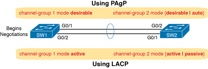
Figure 10-7 Correct EtherChannel Configuration Combinations
Note
Do not use the on parameter on one end, and either auto or desirable (or for LACP, active or passive) on the neighboring switch. The on option uses neither PAgP nor LACP, so a configuration that uses on, with PAgP or LACP options on the other end, would prevent the EtherChannel from working.
For example, in the design shown in Figure 10-7, imagine both physical interfaces on both switches were configured with the channel-group 2 mode desirable interface subcommand. As a result, the two switches would negotiate and create an EtherChannel. Example 10-5 shows the verification of that configuration, with the command show etherchannel 1 port-channel. This command confirms the protocol in use (PAgP, because the desirable keyword was configured), and the list of interfaces in the channel.
Example 10-5 EtherChannel Verification: PAgP Desirable Mode
SW1# show etherchannel 1 port-channel
                 Port-channels in the group:
                 ---------------------------

Port-channel: Po1
------------
Age of the Port-channel   = 0d:00h:04m:04s
Logical slot/port   = 16/1          Number of ports = 2
GC                  = 0x00020001      HotStandBy port = null
Port state          = Port-channel Ag-Inuse
Protocol            = PAgP
Port security       = Disabled
Load share deferral = Disabled

Ports in the Port-channel:

Index   Load   Port     EC state        No of bits
------+------+------+------------------+-----------
  0     00     Gi0/1    Desirable-Sl       0
  0     00     Gi0/2    Desirable-Sl       0

Time since last port bundled: 0d:00h:03m:57s Gi0/2
Physical Interface Configuration and EtherChannels
Even when the channel-group commands have all been configured correctly, other configuration settings can prevent a switch from using a physical port in an EtherChannel—even physical ports manually configured to be part of the channel. The next topic examines those reasons.
First, before using a physical port in an EtherChannel, the switch compares the new physical port’s configuration to the existing ports in the channel. That new physical interface’s settings must be the same as the existing ports’ settings; otherwise, the switch does not add the new link to the list of approved and working interfaces in the channel. That is, the physical interface remains configured as part of the PortChannel, but it is not used as part of the channel, often being placed into some nonworking state.
The list of items the switch checks includes the following:
Speed
Duplex
Operational access or trunking state (all must be access, or all must be trunks)
If an access port, the access VLAN
If a trunk port, the allowed VLAN list (per the switchport trunk allowed command)
If a trunk port, the native VLAN
STP interface settings
In addition, switches check the settings on the neighboring switch. To do so, the switches either use PAgP or LACP (if already in use) or use Cisco Discovery Protocol (CDP) if using manual configuration. When checking neighbors, all settings except the STP settings must match.
As an example, SW1 and SW2 again use two links in one EtherChannel from Figure 10-7. Before configuring the EtherChannel, SW1’s G0/2 was given a different RSTP port cost than G0/1. Example 10-6 picks up the story just after configuring the correct channel-group commands, when the switch is deciding whether to use G0/1 and G0/2 in this.
Example 10-6 Local Interfaces Fail in EtherChannel Because of Mismatched STP Cost
*Mar 1 23:18:56.132: %PM-4-ERR_DISABLE: channel-misconfig (STP) error detected on
 Po1, putting Gi0/1 in err-disable state
*Mar 1 23:18:56.132: %PM-4-ERR_DISABLE: channel-misconfig (STP) error detected on
 Po1, putting Gi0/2 in err-disable state
*Mar 1 23:18:56.132: %PM-4-ERR_DISABLE: channel-misconfig (STP) error detected on
Po1, putting Po1 in err-disable state
*Mar 1 23:18:58.120: %LINK-3-UPDOWN: Interface GigabitEthernet0/1, changed state to
  down
*Mar 1 23:18:58.137: %LINK-3-UPDOWN: Interface Port-channel1, changed state to down
*Mar 1 23:18:58.137: %LINK-3-UPDOWN: Interface GigabitEthernet0/2, changed state to
  down

SW1# show etherchannel summary
Flags:  D - down        P - bundled in port-channel
        I - stand-alone s - suspended
        H - Hot-standby (LACP only)
        R - Layer3      S - Layer2
        U - in use      N - not in use, no aggregation
        f - failed to allocate aggregator

        M - not in use, minimum links not met
        m - not in use, port not aggregated due to minimum links not met
        u - unsuitable for bundling
        w - waiting to be aggregated
        d - default port

        A - formed by Auto LAG

Number of channel-groups in use: 1
Number of aggregators: 1

Group  Port-channel  Protocol    Ports
------+-------------+-----------+-----------------------------------------------
1      Po1(SD)          -        Gi0/1(D) Gi0/2(D)
The messages at the top of the example specifically state what the switch does when determining whether the interface settings match. In this case, SW1 detects the different STP costs. SW1 does not use G0/1, does not use G0/2, and even places them into an err-disabled state. The switch also puts the PortChannel into err-disabled state. As a result, the PortChannel is not operational, and the physical interfaces are also not operational.
To solve this problem, you must reconfigure the physical interfaces to use the same STP settings. In addition, the PortChannel and physical interfaces must be shutdown, and then no shutdown, to recover from the err-disabled state. (Note that when a switch applies the shutdown and no shutdown commands to a PortChannel, it applies those same commands to the physical interfaces, as well; so, just do the shutdown/no shutdown on the PortChannel interface.)
EtherChannel Load Distribution
When using Layer 2 EtherChannels, a switch’s MAC learning process associates MAC addresses with the PortChannel interfaces and not the underlying physical ports. Later, when a switch makes a forwarding decision to send a frame out a PortChannel interface, the switch must do more work: to decide out which specific physical port to use to forward the frame. IOS documentation refers to those rules as EtherChannel load distribution or load balancing. Figure 10-8 shows the main idea.
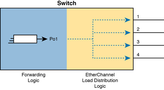
Figure 10-8 Correct EtherChannel Configuration Combinations
Configuration Options for EtherChannel Load Distribution
EtherChannel load distribution makes the choice for each frame based on various numeric values found in the Layer 2, 3, and 4 headers. The process uses one configurable setting as input: the load distribution method as defined with the port-channel load-balance method global command. The process then performs some match against the fields identified by the configured method.
Table 10-4 lists the most common methods. However, note that some switches may support only MAC-based methods, or only MAC- and IP-based methods, depending on the model and software version.
Table 10-4 EtherChannel Load Distribution Methods
Configuration Keyword |
Math Uses… |
Layer |
|---|---|---|
src-mac |
Source MAC address |
2 |
dst-mac |
Destination MAC address |
2 |
src-dst-mac |
Both source and destination MAC |
2 |
src-ip |
Source IP address |
3 |
dst-ip |
Destination IP address |
3 |
src-dst-ip |
Both source and destination IP |
3 |
src-port |
Source TCP or UDP port |
4 |
dst-port |
Destination TCP or UDP port |
4 |
src-dst-port |
Both source and destination TCP or UDP port |
4 |
To appreciate why you might want to use different methods, you need to consider the results of how switches make their choice. (The discussion here focuses on the result, and not the logic, because the logic remains internal to the switch, and Cisco does not document how each switch model or IOS version works internally.) However, the various load distribution algorithms do share some common goals:
To cause all messages in a single application flow to use the same link in the channel, rather than being sent over different links. Doing so means that the switch will not inadvertently reorder the messages sent in that application flow by sending one message over a busy link that has a queue of waiting messages, while immediately sending the next message out an unused link.
To integrate the load distribution algorithm work into the hardware forwarding ASIC so that load distribution works just as quickly as the work to forward any other frame.
To use all the active links in the EtherChannel, adjusting to the addition and removal of active links over time.
Within the constraints of the other goals, balance the traffic across those active links.
In short, the algorithms first intend to avoid message reordering, make use of the switch forwarding ASICs, and use all the active links. However, the algorithm does not attempt to send the exact same number of bits over each link over time. The algorithm does try to balance the traffic, but always within the constraints of the other goals.
Whatever load distribution method you choose, the method identifies fields in the message headers. Any messages in the same application flow will then have the same values in the fields used by the load distribution algorithm and will always be forwarded over the same link. For example, when a user connects to a website, that web server may return thousands of packets to the client. Those thousands of packets should flow over the same link in the EtherChannel.
For instance, with the load distribution method of src-mac (meaning source MAC address), all frames with the same MAC address flow over one link. Figure 10-9 shows the idea with pseudo MAC addresses, with the load distribution sending frames with source MAC 1 over link 1, source MAC 2 over link 2, and source MAC 3 over link 3.
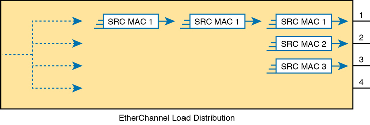
Figure 10-9 Distributing All Frames with Same Mac Out Same Interface
Cisco provides a variety of load distribution options so that the engineer can examine the flows in the network with the idea of finding which fields have the most variety in their values: source and destination MAC, or IP address, or transport layer port numbers. The more variety in the values in the fields, the better the balancing effects, and the lower the chance of sending disproportionate amounts of traffic over one link.
Note
The algorithm focuses on the low-order bits in the fields in the headers because the low-order bits typically differ the most in real networks, while the high-order bits do not differ much. By focusing on the lower-order bits, the algorithm achieves better balancing of traffic over the links.
The Effects of the EtherChannel Load Distribution Algorithm
Figure 10-10 details a new EtherChannel that will be used in two examples to show the effects of load distribution. The examples will focus on frames sent by switch SW1 in the figure, showing the use of the test etherchannel load-balance EXEC command. That command asks the switch to consider some addresses or ports and answer the question: which link would you use when forwarding a message with those address/port values?
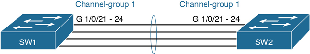
Figure 10-10 Four-Link EtherChannel
Example 10-7 shows how switch SW1 distributes traffic when using src-mac load distribution. The example lists the output from three of the test etherchannel load-balance commands, but note that all three commands use the same source MAC address. As a result, the answer from each command references the same interface (G1/0/22 in this case).
Example 10-7 Testing with Identical Source MACs When Using src-mac Balancing
SW1# show etherchannel load-balance
EtherChannel Load-Balancing Configuration:
        src-mac

EtherChannel Load-Balancing Addresses Used Per-Protocol:
Non-IP: Source MAC address
  IPv4: Source MAC address
  IPv6: Source MAC address

SW1# test etherchannel load-balance interface po1 mac 0200.0000.0001 0200.1111.1111
Would select Gi1/0/22 of Po1

SW1# test etherchannel load-balance interface po1 mac 0200.0000.0001 0200.1111.1112
Would select Gi1/0/22 of Po1

SW1# test etherchannel load-balance interface po1 mac 0200.0000.0001 0200.1111.1113
Would select Gi1/0/22 of Po1
Example 10-7 makes two important points:
All three tests list the same outgoing physical interface because (1) the method uses only the source MAC address, and (2) all three tests use the same MAC addresses.
All three tests use a different destination MAC address, with different low-order bits, but that had no impact on the choice because the method—src-mac—does not consider the destination MAC address.
In contrast on that first point, Example 10-8 repeats the test commands from Example 10-7. The switch still uses the src-mac balancing method, but now with different source MAC addresses in each test. Notice that the source MAC addresses used in the tests differ by just a few bit values in the low-order bits, so as a result, each test shows a different interface choice by SW1.
Example 10-8 Testing with Source MACs with Low-Order Bit Differences
SW1# test etherchannel load-balance interface po1 mac 0200.0000.0001 0200.1111.1111
Would select Gi1/0/22 of Po1

SW1# test etherchannel load-balance interface po1 mac 0200.0000.0002 0200.1111.1111
Would select Gi1/0/24 of Po1

SW1# test etherchannel load-balance interface po1 mac 0200.0000.0003 0200.1111.1111
Would select Gi1/0/23 of Po1
Example 10-9 shows yet a third variation, this time changing the load distribution method to src-dst-mac, which means that the switch will consider both source and destination MAC. The example repeats the exact same test etherchannel commands as Example 10-7, with the exact same MAC addresses: the source MAC addresses remain the same in all three tests, but the destination MAC addresses differ in the low-order bits. With the chosen destination MAC values differing slightly, switch SW1 happens to choose three different interfaces.
Example 10-9 Evidence of Source and Destination MAC Load Distribution
SW1# config t
Enter configuration commands, one per line.  End with CNTL/Z.
SW1(config)# port-channel load-balance src-dst-mac
SW1(config)# ^Z
SW1#
SW1# show etherchannel load-balance
EtherChannel Load-Balancing Configuration:
        src-dst-mac

EtherChannel Load-Balancing Addresses Used Per-Protocol:
Non-IP: Source XOR Destination MAC address
  IPv4: Source XOR Destination MAC address
  IPv6: Source XOR Destination MAC address

SW1# test etherchannel load-balance interface po1 mac 0200.0000.0001 0200.1111.1111
Would select Gi1/0/22 of Po1

SW1# test etherchannel load-balance interface po1 mac 0200.0000.0001 0200.1111.1112
Would select Gi1/0/24 of Po1

SW1# test etherchannel load-balance interface po1 mac 0200.0000.0001 0200.1111.1113
Would select Gi1/0/23 of Po1
Chapter Review
One key to doing well on the exams is to perform repetitive spaced review sessions. Review this chapter’s material using either the tools in the book or interactive tools for the same material found on the book’s companion website. Refer to the “Your Study Plan” element for more details. Table 10-5 outlines the key review elements and where you can find them. To better track your study progress, record when you completed these activities in the second column.
Table 10-5 Chapter Review Tracking
Review Element |
Review Date(s) |
Resource Used |
|---|---|---|
Review key topics |
|
Book, website |
Review key terms |
|
Book, website |
Answer DIKTA questions |
|
Book, PTP |
Review config checklists |
|
Book, website |
Review command tables |
|
Book |
Review memory tables |
|
Website |
Do labs |
|
Blog |
Review All the Key Topics
Table 10-6 Key Topics for Chapter 10
Key Topic Element |
Description |
Page Number |
|---|---|---|
Typical design choice for which switches should be made to be root |
241 |
|
Conceptual view of load-balancing benefits of PVST+ |
242 |
|
STP Standards and Configuration Options |
243 |
|
Shows the format of the system ID extension of the STP priority field |
243 |
|
List |
Facts about RPVST+’s methods versus RSTP |
246 |
List |
Steps to manually configure an EtherChannel |
248 |
List |
Items a switch compares in a new physical port’s configuration to the existing ports in the channel |
252 |
Key Terms You Should Know
Command References
Tables 10-7 and 10-8 list configuration and verification commands used in this chapter. As an easy review exercise, cover the left column in a table, read the right column, and try to recall the command without looking. Then repeat the exercise, covering the right column, and try to recall what the command does.
Table 10-7 Chapter 10 Configuration Command Reference
Command |
Description |
|---|---|
spanning-tree mode {pvst | rapid-pvst | mst} |
Global configuration command to set the STP mode. |
spanning-tree [vlan vlan-number] root primary |
Global configuration command that changes this switch to the root switch. The switch’s priority is changed to the lower of either 24,576 or 4096 less than the priority of the current root bridge when the command was issued. |
spanning-tree [vlan vlan-number] root secondary |
Global configuration command that sets this switch’s STP base priority to 28,672. |
spanning-tree vlan vlan-id priority priority |
Global configuration command that changes the bridge priority of this switch for the specified VLAN. |
spanning-tree [vlan vlan-number] cost cost |
Interface subcommand that changes the STP cost to the configured value. |
spanning-tree [vlan vlan-number] port-priority priority |
Interface subcommand that changes the STP port priority in that VLAN (0 to 240, in increments of 16). |
channel-group channel-group-number mode {auto | desirable | active | passive | on} |
Interface subcommand that enables EtherChannel on the interface. |
Table 10-8 Chapter 10 EXEC Command Reference
Command |
Description |
|---|---|
show spanning-tree |
Lists details about the state of STP on the switch, including the state of each port. |
show spanning-tree vlan vlan-id |
Lists STP information for the specified VLAN. |
show etherchannel [channel-group-number] {brief | detail | port | port-channel | summary} |
Lists information about the state of EtherChannels on this switch. |